EP0202836B1 - Air supply pump - Google Patents
Air supply pump Download PDFInfo
- Publication number
- EP0202836B1 EP0202836B1 EP86303588A EP86303588A EP0202836B1 EP 0202836 B1 EP0202836 B1 EP 0202836B1 EP 86303588 A EP86303588 A EP 86303588A EP 86303588 A EP86303588 A EP 86303588A EP 0202836 B1 EP0202836 B1 EP 0202836B1
- Authority
- EP
- European Patent Office
- Prior art keywords
- pump
- diaphragm
- air
- housing
- outlet
- Prior art date
- Legal status (The legal status is an assumption and is not a legal conclusion. Google has not performed a legal analysis and makes no representation as to the accuracy of the status listed.)
- Expired
Links
- 239000002184 metal Substances 0.000 claims description 33
- 230000002093 peripheral effect Effects 0.000 claims description 17
- 239000004020 conductor Substances 0.000 claims description 11
- 238000004891 communication Methods 0.000 claims description 4
- 239000003570 air Substances 0.000 description 56
- 238000010276 construction Methods 0.000 description 3
- 230000007246 mechanism Effects 0.000 description 3
- 238000005086 pumping Methods 0.000 description 3
- 238000010586 diagram Methods 0.000 description 2
- 230000001133 acceleration Effects 0.000 description 1
- 239000012080 ambient air Substances 0.000 description 1
- 238000006243 chemical reaction Methods 0.000 description 1
- 230000006835 compression Effects 0.000 description 1
- 238000007906 compression Methods 0.000 description 1
- 238000007796 conventional method Methods 0.000 description 1
- 230000009977 dual effect Effects 0.000 description 1
- 230000000694 effects Effects 0.000 description 1
- 230000035945 sensitivity Effects 0.000 description 1
- 238000000926 separation method Methods 0.000 description 1
- 239000011800 void material Substances 0.000 description 1
Images

Classifications
-
- F—MECHANICAL ENGINEERING; LIGHTING; HEATING; WEAPONS; BLASTING
- F04—POSITIVE - DISPLACEMENT MACHINES FOR LIQUIDS; PUMPS FOR LIQUIDS OR ELASTIC FLUIDS
- F04B—POSITIVE-DISPLACEMENT MACHINES FOR LIQUIDS; PUMPS
- F04B43/00—Machines, pumps, or pumping installations having flexible working members
- F04B43/0009—Special features
- F04B43/0027—Special features without valves
-
- F—MECHANICAL ENGINEERING; LIGHTING; HEATING; WEAPONS; BLASTING
- F04—POSITIVE - DISPLACEMENT MACHINES FOR LIQUIDS; PUMPS FOR LIQUIDS OR ELASTIC FLUIDS
- F04B—POSITIVE-DISPLACEMENT MACHINES FOR LIQUIDS; PUMPS
- F04B43/00—Machines, pumps, or pumping installations having flexible working members
- F04B43/02—Machines, pumps, or pumping installations having flexible working members having plate-like flexible members, e.g. diaphragms
- F04B43/04—Pumps having electric drive
- F04B43/043—Micropumps
- F04B43/046—Micropumps with piezoelectric drive
Definitions
- the present invention relates generally to air supply pumps, in particular air pumps used to deliver supply air to fluidic devices or systems.
- Piezoelectrically driven diaphragm pumps have, for some time, been considered as possible alternatives to electromagnetically driven pumps due to the well-known piezoelectric drive characteristics of lighter weight, greater frequency response and considerably smaller size.
- piezoelectric drives in fluidic air supply pumps has so far not resulted in wholly satisfactory structural simplicity, compactness, supply flow characteristics or pumping efficiency.
- an air supply pump comprising a housing defining a chamber and an outlet communicating with the chamber, the chamber being divided into first and second portions by a diaphragm which is vibratable between first and second positions, characterised in that the outlet is divided into first and second portions by the diaphragm, the first outlet portion being in communication with the first chamber portion and the second outlet portion being in communication with the second chamber portion whereby movement of the diaphragm to its first position expels air from the first chamber portion via the first outlet portion while drawing air into the second chamber portion via the second outlet portion and movement of the diaphragm to its second position expels air from the second chamber portion via the second outlet portion while drawing air into the first chamber portion via the first outlet portion.
- the housing includes first and second housing members and the diaphragm includes a metal disc which is clamped between the first and second housing members around an annular portion spaced inwards from its peripheral edge, leaving an annular peripheral portion unrestrained.
- the two housing members include axially projecting portions in the form of cylindrical bosses, and the disc is clamped between a flattened annular peripheral surface at the distal end of each boss, the flatted peripheral surfaces being in a facing, aligned relationship.
- the peripheral edges of the housing members are in alignment, and the diaphragm has a portion which projects outwardly beyond aligned peripheral edges of housing members.
- the pump includes an air receiver for collecting the expulsions of air from the outlet portions to create a pulsating air supply for delivery to a fluidic device.
- the metal disc preferably includes a portion which projects outwards through the outlet, the air receiver is carried by the housing and the air receiver has an inlet which faces the outlet and is closely adjacent the outwardly projecting portion of the diaphragm.
- baffle interposed between the outlet channels and the air receiver inlet for substantially preventing air being expelled from one of the channels from being drawn into the other channel.
- the means defining such a baffle comprises the outwardly projecting portion of the diaphragm.
- the diaphragm or disc and the housing members each have a substantially identical coefficient of thermal expansion.
- the housing is of metal; the diaphragm includes a metal disc; and the means for using electrical energy include: first and second terminals carried by the housing for receiving an alternating electrical current, the first terminal being insulated from the housing and the second terminal being connected thereto, and two piezoelectric elements secured in opposite polarity to opposite sides of the metal disc, the first terminal being connected to the piezoelectric elements.
- the present invention provides a fluidic air supply pump which eliminates or minimises a variety of problems and limitations commonly associated with conventional diaphragm and other types of pumps proposed for use in fluidic applications.
- the pump according to the invention may be very compact, relatively simple and inexpensive in construction, light in weight, rugged and efficient - all of which make it particularly well suited to the fluidic air supply applications for which it is intended.
- a compact piezoelectric fluidic air supply pump which comprises first and second housing members, and a diaphragm member having piezoelectric elements secured, in an opposite polarity relationship, to opposite side surfaces thereof.
- Each of the housing members has a centrally positioned surface depression formed therein and an outlet channel extending between the depression and the exterior surface of the housing member.
- the diaphragm member With these depressions and channels of the two housing members facing each other in an aligned relationship, the diaphragm member is clamped between the housing members in a position such that it completely separates the depression and outlet channel of one housing member from the depression and outlet channel of the other housing member.
- an air receiver is provided to capture and collect the outward air pulses, and create therefrom a pulsating air supply stream for delivery to a fluidic device or system.
- a peripheral portion of the diaphragm member extends outwardly of the housing, between the facing outlet channels, and serves as a baffle to prevent air being expelled through either channel from being drawn into the housing through the other channel.
- Another preferred feature of the invention which is believed to be significant is the fact that the performance of the pump may be substantially improved by clamping the diaphragm member between the housing members only around a peripheral portion of the diaphragm member spaced inwardly from its peripheral edged.
- FIG. 1 illustrates schematically, a compact piezoelectric air pump 20 which embodies principles of the present invention and is used to supply a rapidly pulsating air stream 22 to a fluidic device or system 24.
- the pump 20 is electrically driven by a suitable current inverter 26 which receives direct current, via leads 28 and 30, and supplies alternating current to the pump via leads 32 and 34.
- the lead 34 includes a tuned inductor 36.
- the inverter is used in typical fluidic applications where only DC electrical power is available. If however, AC electrical power is available, the inverter 26 may be omitted and AC power can be supplied directly to the pump through the leads 32,34.
- the pump 20 includes a thin, disc-shaped metal diaphragm member 38 ( Figures 2 and 4) having smaller diameter piezoelectric disc element 40, 42 coaxially secured in mutually reversed polarity to its opposite side surfaces.
- AC lead 34 is connected to the piezoelectric disc elements 40, 42 and the AC lead 32 is connected to the metal diaphragm or disc 38 ( Figure 2).
- the pump 20 in addition to the diaphragm 38 and piezoelectric disc elements 40 and 42, the pump 20 also includes a compact metal housing 44 having a generally disc-shaped upper member 44a and a generally disc-shaped lower member 44b.
- the upper housing member 44a is truncated to define a flattened edge 46, while an upper end portion of the lower housing member 44b is similarly truncated to define a flattened edge 48 which projects upwardly from a ledge portion 50 of the lower housing member 44b.
- the two housing members 44a, 44b are clamped together, with the flattened edges 46, 48 in alignment, by suitable fastening means such as rivets 52 that extend through openings 54, 56 respectively formed in the housing members 44a, 44b. Alignment of the flattened edges 46, 48 is facilitated by a circumferentially spaced series of alignment pins 58 which project from the lower housing member 44b, and which are received in corresponding openings 60 formed in the upper housing member 44a. The pins project upwards from the inner surface 62 of the lower housing member 44b.
- a cylindrical boss 64 projects upwards from the inner surface 62, generally at its central portion. At the periphery of the upper end of boss 64, there is a narrow, upwardly facing annular flattened edge 66 ( Figures 4 and 12). From the edge 64, the upper part of the boss 64 is recessed inwards along a sloping, annular surface 68 which terminates at a circular flat surface 70. A channel 72 is cut into the upper end of the boss 64 and extends from the flat surface 70, upwards along the sloped surface 68, and opens outwards through the flattened edge 48 via a necked channel outlet 74 of rectangular configuration.
- the upper housing member 44a also has cylindrical boss 76 which projects downwards from its inner surface 78 generally at its central portion.
- the boss 76 is of identical configuration to, and is aligned with, the lower boss 64, having an annular flattened edge 80, a sloping annular surface 82, and a circular flat central surface 84.
- the upper boss 76 has a channel (not shown) which extends from the central surface 84, downwards along the sloped annular surface 82 and opens outwards through the flattened edge 46 ( Figures 4 and 11) via a necked channel outlet 86 of rectangular configuration.
- the metal disc 38 is coaxially clamped between the aligned end surfaces 66, 80 of the bosses 64, 76 in a manner which is believed to be unique and which is believed to enhance significantly the air delivery and various other operating characteristics of the pump 20.
- This coaxial relation between the metal disc 38 and the boss surfaces 64, 80 is maintained by alignment pins 58 which prevent the metal disc 38 from shifting relative to the boss ends.
- the metal disc 38 is clamped only around an annular portion which is positioned inwardly of its peripheral edge 88.
- the diameter of the metal disc 38 is slightly larger than the diameters of the bosses 64, 76 so that an annular portion 90 of the metal disc projects out from the side surfaces of the bosses.
- This peripheral portion of the metal disc is totally unrestrained, being disposed within an annular housing void 92 positioned between the spaced apart inner side surfaces 78, 62 of the upper and lower housing members 44a, 44b.
- the entire central portion of the metal disc 38 is unrestrained, being positioned inwards of the boss clamping surfaces 64, 76 in the facing boss recesses defined by the surfaces 82, 84 and 68, 70.
- the assembly comprising the metal disc 38 and piezolectric discs 42, 44 divides and separates the facing boss end recesses (which collectively define an interior housing chamber) into an upper subchamber 94 and a lower subchamber 96 ( Figure 10 and 11).
- the metal disc 38 divides and separates the facing channel outlets 74, 86 (which collectively define a chamber outlet) and has a portion 98 which projects out from the aligned housing member truncated surfaces 46, 48.
- an air receiving member 100 ( Figures 3, 4 and 11) which is secured to the lower housing member ledge 50 by screws 102 received in threaded openings 104 in the ledge 50.
- the air receiver 100 has an inlet 106 and an outlet 108 ( Figure 10) which is in registry with an outlet opening 110 ( Figures 4 and 10) that extends through the housing ledge 50.
- the receiver inlet 106 faces the aligned channel outlets 74, 86 and extends axially beyond each of the opposite sides surfaces of the metal disc 38.
- terminals are provided in the form of a power pin 112 and a ground pin 114, the power pin 112 being connected to the AC lead 34, and the ground pin 114 being connected to the AC lead 32.
- the power pin 112 extends down through a relatively large diameter opening 116 formed in the upper housing member 44a, and is anchored at its lower end to an insulating bushing 118.
- the bushing 118 is carried by the lower housing member 44b and insulates the power pin 112 from the metal housing.
- the lower end of the power pin 112 is connected to one end of a flat insulated wire 122 (Figure 8). From its end connection to the power pin 112 to wire 122 extends along a recess 124 which begins at the lower end of the power pin 112 and continues along the underside of housing member 44b, up through each housing member adjacent their peripheries and across the upper side surface of the upper housing member 44a.
- the opposite end of the wire 122 is connected to a metal stud 126, while at an intermediate position, the wire is connected to another metal stud 128.
- a portion of the wire 122 adjacent its upper end is folded over on itself, as at 122a, to facilitate separation of the housing members 44a, 44b during disassembly, as best illustrated in Figure 5.
- the first stud 126 is received in a bushing 130, carried by a central portion of upper housing member 44a ( Figure 9), which insulates the stud from the metal housing.
- the other stud 128 is received in a centrally disposed bushing 132 carried by the lower housing member 44b.
- the inner end of this stud 126 is connected to a central portion of an elongated, flexible metal conductor element 134 located within the subchamber 94, while the inner end of the stud 128 is connected to a central portion of an elongate flexible metal conductor element 136 located within the subchamber 96.
- the ends of the conductor 134 are bent downwards into a biased engagement with the piezoelectric element 40, while the ends of the conductor 136 are bent upwards into a biased engagement with the piezoelectric element 42.
- the ground pin 114 is in electrical connection with the housing members 44a and 44b.
- the forgoing structure defines between the power and ground pins 112, 114 an electrical current path extending from the power pin 112 through the wire 122 to the studs 126, 128, from the studs to the piezoelectric elements 40, 42 through the conductors 134, 136, and from the piezoelectric elements to the ground pin 114 via the metal disc 38 and the housing members 44a, 44b.
- the opposite ends of the conductor 134 are forced further apart while sliding along the piezoelectric element 40, and the opposite ends of the conductor 136 move closer together while sliding along the piezoelectric element 42.
- the sliding movement of the conductors is reversed as the disc is deflected toward its downward position 38b.
- the described vibration of the disc 38 causes alternate compression and expansion of the housing subchambers 94, 96.
- a high velocity burst of air 138 ( Figure 11) is expelled out through the channel outlet 86 from the subchamber 94. Due to its relatively high kinetic energy, the air 138 is forced directly into the closely adjacent receiver inlet 106. Simultaneously, ambient air 140 is drawn into the expanding subchamber 96 via the channel outlet 74.
- the deflective direction of the disc 38 reverses, the direction of air flow through the channel outlets 74, 86 is also reversed, causing a high velocity burst of air 142 to be expelled from the channel outlet 74.
- the air burst 142 is forced into the receiver outlet 106, such air bursts 138, 142 collectively forming the pulsating air stream 22 used as supply air for the fluidic device or system 24 shown in Figure 1.
- the vibrating diaphragm 38 creates two usable supply air streams (138 and 142) during each complete vibrational cycle. This is, of course, far more efficient than the variety of conventional diaphragm pumps which can generate a supply air flow only when the particular diaphragm is moving in a single one of its two deflectional directions (i.e., creating only a single burst of supply air during its entire vibrational cycle).
- each of the outlets 74, 76 to supply air to the receiver 100 is achieved without the use of check valve mechanisms of any sort - each of the channels 74, 86 is totally unrestricted.
- This significant structural simplification vis a vis conventional diaphragm pump construction is achieved in part by a unique dual use of the disc 38. Specifically, the disc is not only used to divide and separate the subchambers 94, 96 and the air outlets 74, 86, but its projecting portion 98 also serves as an air flow baffle interposed between the channel outlets 74, 86 and the receiver inlet 106.
- this portion 98 substantially prevents the supply air burst 138 from being drawn back into the outlet 74, and the supply air burst 142 from being drawn back into the outlet 86. It also causes the receiver 100 to function, in effect, as a simple fluidic rectifier, helping to guide the air bursts 138, 142 into the receiver inlet 106 while assisting in preventing reverse flow outwardly through such inlet 106.
Description
- The present invention relates generally to air supply pumps, in particular air pumps used to deliver supply air to fluidic devices or systems.
- Various types of air pumping mechanisms have been used to supply pressurised air to "fluidic" devices, i.e. devices which use small, high velocity air jets to perform various control and sensing functions, as opposed to more conventional mechanical or electrical control and sensing devices. However, for a variety of reasons, none of these prior pumping mechanisms has proven to be entirely satisfactory in fluidic air supply applications.
- One such example is a solenoid-operated reciprocating diaphragm pump. This type of pump, though fairly simple in construction, has the disadvantages, in fluidic applications, of undesirable low frequency operation pressure ripple, and acceleration sensitivity due to the relatively high diaphragm mass required.
- Piezoelectrically driven diaphragm pumps have, for some time, been considered as possible alternatives to electromagnetically driven pumps due to the well-known piezoelectric drive characteristics of lighter weight, greater frequency response and considerably smaller size. However, in practice, the use of piezoelectric drives in fluidic air supply pumps has so far not resulted in wholly satisfactory structural simplicity, compactness, supply flow characteristics or pumping efficiency.
- Accordingly, it is an object of the present invention to provide a fluidic air supply pump having, compared to conventional air pumps, improved structural and functional characteristics.
- It is a further object of the present invention to provide such a pump which works on the piezoelectric principle.
- According to the invention there is provided an air supply pump comprising a housing defining a chamber and an outlet communicating with the chamber, the chamber being divided into first and second portions by a diaphragm which is vibratable between first and second positions, characterised in that the outlet is divided into first and second portions by the diaphragm, the first outlet portion being in communication with the first chamber portion and the second outlet portion being in communication with the second chamber portion whereby movement of the diaphragm to its first position expels air from the first chamber portion via the first outlet portion while drawing air into the second chamber portion via the second outlet portion and movement of the diaphragm to its second position expels air from the second chamber portion via the second outlet portion while drawing air into the first chamber portion via the first outlet portion.
- Preferably the housing includes first and second housing members and the diaphragm includes a metal disc which is clamped between the first and second housing members around an annular portion spaced inwards from its peripheral edge, leaving an annular peripheral portion unrestrained. Preferably, also, the two housing members include axially projecting portions in the form of cylindrical bosses, and the disc is clamped between a flattened annular peripheral surface at the distal end of each boss, the flatted peripheral surfaces being in a facing, aligned relationship. Preferably, therefore, the peripheral edges of the housing members are in alignment, and the diaphragm has a portion which projects outwardly beyond aligned peripheral edges of housing members.
- Preferably, the pump includes an air receiver for collecting the expulsions of air from the outlet portions to create a pulsating air supply for delivery to a fluidic device. Thus, the metal disc preferably includes a portion which projects outwards through the outlet, the air receiver is carried by the housing and the air receiver has an inlet which faces the outlet and is closely adjacent the outwardly projecting portion of the diaphragm. Preferably therefore, there is an air receiver carried by one of the housing members, the inlet facing the aligned peripheral edges and being closely adjacent the projecting portion of the diaphragm, the air receiver being positioned to receive the air expelled from both of the outlet channels.
- There is preferably some means defining a baffle interposed between the outlet channels and the air receiver inlet for substantially preventing air being expelled from one of the channels from being drawn into the other channel. Conveniently, the means defining such a baffle comprises the outwardly projecting portion of the diaphragm.
- Preferably, the diaphragm or disc and the housing members each have a substantially identical coefficient of thermal expansion.
- Preferably, there are means for using electrical energy from a source thereof to cause vibration of the diaphragm. Preferably, the housing is of metal; the diaphragm includes a metal disc; and the means for using electrical energy include: first and second terminals carried by the housing for receiving an alternating electrical current, the first terminal being insulated from the housing and the second terminal being connected thereto, and two piezoelectric elements secured in opposite polarity to opposite sides of the metal disc, the first terminal being connected to the piezoelectric elements. Preferably, there are two flexible conductors each positioned in the chamber and slidably engaging one of the piezoelectric elements.
- It is believed that the present invention provides a fluidic air supply pump which eliminates or minimises a variety of problems and limitations commonly associated with conventional diaphragm and other types of pumps proposed for use in fluidic applications. The pump according to the invention may be very compact, relatively simple and inexpensive in construction, light in weight, rugged and efficient - all of which make it particularly well suited to the fluidic air supply applications for which it is intended.
- In carrying out principles of the present invention, in accordance with a preferred embodiment thereof, a compact piezoelectric fluidic air supply pump can be provided which comprises first and second housing members, and a diaphragm member having piezoelectric elements secured, in an opposite polarity relationship, to opposite side surfaces thereof. Each of the housing members has a centrally positioned surface depression formed therein and an outlet channel extending between the depression and the exterior surface of the housing member.
- With these depressions and channels of the two housing members facing each other in an aligned relationship, the diaphragm member is clamped between the housing members in a position such that it completely separates the depression and outlet channel of one housing member from the depression and outlet channel of the other housing member.
- When an alternating electrical current is applied to oppositely disposed piezoelectric elements the diaphragm member is caused to vibrate laterally within the assembled housing. This vibration creates alternate outward and inward air pulses through each of the diaphragm-separated outlet channels. Preferably, an air receiver is provided to capture and collect the outward air pulses, and create therefrom a pulsating air supply stream for delivery to a fluidic device or system.
- One significant preferred feature of the present invention, is believed to be the fact that a peripheral portion of the diaphragm member extends outwardly of the housing, between the facing outlet channels, and serves as a baffle to prevent air being expelled through either channel from being drawn into the housing through the other channel.
- Another preferred feature of the invention, which is believed to be significant is the fact that the performance of the pump may be substantially improved by clamping the diaphragm member between the housing members only around a peripheral portion of the diaphragm member spaced inwardly from its peripheral edged.
- The invention may be carried into practice in various ways and one embodiment will now be described by way of example with reference to the accompanying drawings in which:
- Figure 1 is a schematic diagram depicting a piezoelectric air pump embodying principles of the present invention, and a current inverter used to power the pump;
- Figure 2 is a simplified circuit diagram showing the electrical connections to the diaphragm and piezoelectric portions of the pump;
- Figure 3 is a top perspective view of an assembled pump;
- Figure 4 is an exploded perspective view of the pump shown in Figure 3;
- Figure 5 is a smaller scale exploded perspective view of the two-piece housing of the pump shown in Figure 3;
- Figure 6 is a bottom perspective view of the assembled pump shown in Figure 3;
- Figure 7 is a reduced scale top plan view of the pump shown in Figure 3;
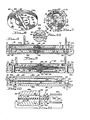
- Figure 8 is a cross-sectional view, to an enlarged scale, taken through the pump along the line 8 - 8 of Figure 7;
- Figure 9 is a cross-sectional view, to an enlarged scale taken through the pump along line 9 - 9 of Figure 7;
- Figure 10 is a cross-sectional view to an enlarged scale, taken through the pump along line 10 - 10 of Figure 7, with certain interior portions of the pump being omitted for clarity;
- Figure 11 is a cross-sectional enlargement of area "11" in Figure 10; and
- Figure 12 is an exploded cross-sectional enlargement of area "A" in Figure 8.
- Figure 1 illustrates schematically, a compact
piezoelectric air pump 20 which embodies principles of the present invention and is used to supply a rapidly pulsatingair stream 22 to a fluidic device or system 24. Thepump 20 is electrically driven by a suitable current inverter 26 which receives direct current, via leads 28 and 30, and supplies alternating current to the pump vialeads 32 and 34. The lead 34 includes a tunedinductor 36. - The inverter is used in typical fluidic applications where only DC electrical power is available. If however, AC electrical power is available, the inverter 26 may be omitted and AC power can be supplied directly to the pump through the
leads 32,34. - As subsequently described in greater detail, the
pump 20 includes a thin, disc-shaped metal diaphragm member 38 (Figures 2 and 4) having smaller diameterpiezoelectric disc element 40, 42 coaxially secured in mutually reversed polarity to its opposite side surfaces. Via other structural elements the, AC lead 34 is connected to thepiezoelectric disc elements 40, 42 and theAC lead 32 is connected to the metal diaphragm or disc 38 (Figure 2). - The actual structure of the
pump 20 will now be described. - Referring firstly to Figures 3 and 4, in addition to the
diaphragm 38 andpiezoelectric disc elements 40 and 42, thepump 20 also includes acompact metal housing 44 having a generally disc-shaped upper member 44a and a generally disc-shapedlower member 44b. The upper housing member 44a is truncated to define aflattened edge 46, while an upper end portion of thelower housing member 44b is similarly truncated to define aflattened edge 48 which projects upwardly from aledge portion 50 of thelower housing member 44b. - The two
housing members 44a, 44b are clamped together, with theflattened edges rivets 52 that extend throughopenings housing members 44a, 44b. Alignment of theflattened edges alignment pins 58 which project from thelower housing member 44b, and which are received incorresponding openings 60 formed in the upper housing member 44a. The pins project upwards from theinner surface 62 of thelower housing member 44b. - A
cylindrical boss 64 projects upwards from theinner surface 62, generally at its central portion. At the periphery of the upper end ofboss 64, there is a narrow, upwardly facing annular flattened edge 66 (Figures 4 and 12). From theedge 64, the upper part of theboss 64 is recessed inwards along a sloping,annular surface 68 which terminates at a circular flat surface 70. A channel 72 is cut into the upper end of theboss 64 and extends from the flat surface 70, upwards along thesloped surface 68, and opens outwards through theflattened edge 48 via a necked channel outlet 74 of rectangular configuration. - Referring now to Figures 9 and 12, the upper housing member 44a also has
cylindrical boss 76 which projects downwards from itsinner surface 78 generally at its central portion. Theboss 76 is of identical configuration to, and is aligned with, thelower boss 64, having an annularflattened edge 80, a slopingannular surface 82, and a circular flatcentral surface 84. As in the case of thelower boss 64, theupper boss 76 has a channel (not shown) which extends from thecentral surface 84, downwards along the slopedannular surface 82 and opens outwards through the flattened edge 46 (Figures 4 and 11) via anecked channel outlet 86 of rectangular configuration. - The
metal disc 38 is coaxially clamped between the aligned end surfaces 66, 80 of thebosses pump 20. This coaxial relation between themetal disc 38 and the boss surfaces 64, 80 is maintained byalignment pins 58 which prevent themetal disc 38 from shifting relative to the boss ends. - The
metal disc 38 is clamped only around an annular portion which is positioned inwardly of itsperipheral edge 88. As can be seen in Figures 8 - 10 and 11, the diameter of themetal disc 38 is slightly larger than the diameters of thebosses annular portion 90 of the metal disc projects out from the side surfaces of the bosses. This peripheral portion of the metal disc is totally unrestrained, being disposed within an annular housing void 92 positioned between the spaced apart inner side surfaces 78, 62 of the upper andlower housing members 44a, 44b. Similarly, the entire central portion of themetal disc 38 is unrestrained, being positioned inwards of the boss clamping surfaces 64, 76 in the facing boss recesses defined by thesurfaces - With the pump housing assembled as shown, the assembly comprising the
metal disc 38 andpiezolectric discs 42, 44 divides and separates the facing boss end recesses (which collectively define an interior housing chamber) into anupper subchamber 94 and a lower subchamber 96 (Figure 10 and 11). Moreover, as can be best seen in Figures 3 and 11, themetal disc 38 divides and separates the facing channel outlets 74, 86 (which collectively define a chamber outlet) and has aportion 98 which projects out from the aligned housing member truncated surfaces 46, 48. - Closely adjacent this projecting
disc portion 98 is an air receiving member 100 (Figures 3, 4 and 11) which is secured to the lowerhousing member ledge 50 byscrews 102 received in threadedopenings 104 in theledge 50. Theair receiver 100 has aninlet 106 and an outlet 108 (Figure 10) which is in registry with an outlet opening 110 (Figures 4 and 10) that extends through thehousing ledge 50. Thereceiver inlet 106 faces the alignedchannel outlets 74, 86 and extends axially beyond each of the opposite sides surfaces of themetal disc 38. - To receive alternating current from the conversion system 26, terminals are provided in the form of a
power pin 112 and aground pin 114, thepower pin 112 being connected to the AC lead 34, and theground pin 114 being connected to theAC lead 32. As can best be seen in Figure 8 thepower pin 112 extends down through a relativelylarge diameter opening 116 formed in the upper housing member 44a, and is anchored at its lower end to an insulatingbushing 118. Thebushing 118 is carried by thelower housing member 44b and insulates thepower pin 112 from the metal housing. - The lower end of the
power pin 112 is connected to one end of a flat insulated wire 122 (Figure 8). From its end connection to thepower pin 112 towire 122 extends along arecess 124 which begins at the lower end of thepower pin 112 and continues along the underside ofhousing member 44b, up through each housing member adjacent their peripheries and across the upper side surface of the upper housing member 44a. The opposite end of thewire 122 is connected to ametal stud 126, while at an intermediate position, the wire is connected to anothermetal stud 128. A portion of thewire 122 adjacent its upper end is folded over on itself, as at 122a, to facilitate separation of thehousing members 44a, 44b during disassembly, as best illustrated in Figure 5. - The
first stud 126 is received in abushing 130, carried by a central portion of upper housing member 44a (Figure 9), which insulates the stud from the metal housing. In a similar manner, theother stud 128 is received in a centrally disposedbushing 132 carried by thelower housing member 44b. The inner end of thisstud 126 is connected to a central portion of an elongated, flexiblemetal conductor element 134 located within thesubchamber 94, while the inner end of thestud 128 is connected to a central portion of an elongate flexiblemetal conductor element 136 located within thesubchamber 96. The ends of theconductor 134 are bent downwards into a biased engagement with thepiezoelectric element 40, while the ends of theconductor 136 are bent upwards into a biased engagement with the piezoelectric element 42. - The
ground pin 114 is in electrical connection with thehousing members 44a and 44b. - As can be seen in Figures 8 and 9, the forgoing structure defines between the power and ground pins 112, 114 an electrical current path extending from the
power pin 112 through thewire 122 to thestuds piezoelectric elements 40, 42 through theconductors ground pin 114 via themetal disc 38 and thehousing members 44a, 44b. - The operation of the
pump 20 will now be described. - Referring now to Figures 8 - 10, when alternating current is supplied to the power and ground pins 112, 114 via the
leads 32, 34, the opposite polaritypiezoelectric elements 40, 42 cause rapid vibratory deflection of the disc 38 (also referred to herein as a diaphragm) within the pump housing interior between the upper and lower deflectedpositions 38a, 38b indicated by the broken lines in Figure 10. It should be noted that during this vibration of thedisc 38, constant contact is maintained between theflexible conductors piezoelectric elements 40, 42 which they engage. Specifically, as thedisc 38 is deflected upwards, the opposite ends of theconductor 134 are forced further apart while sliding along thepiezoelectric element 40, and the opposite ends of theconductor 136 move closer together while sliding along the piezoelectric element 42. The sliding movement of the conductors is reversed as the disc is deflected toward itsdownward position 38b. - The described vibration of the
disc 38 causes alternate compression and expansion of thehousing subchambers channel outlet 86 from thesubchamber 94. Due to its relatively high kinetic energy, theair 138 is forced directly into the closelyadjacent receiver inlet 106. Simultaneously,ambient air 140 is drawn into the expandingsubchamber 96 via the channel outlet 74. As the deflective direction of thedisc 38 reverses, the direction of air flow through thechannel outlets 74, 86 is also reversed, causing a high velocity burst ofair 142 to be expelled from the channel outlet 74. Like its alternatingcounterpart 138, theair burst 142 is forced into thereceiver outlet 106, such air bursts 138, 142 collectively forming the pulsatingair stream 22 used as supply air for the fluidic device or system 24 shown in Figure 1. - At this point, several advantageous features of the
pump 20 should be noted. Firstly, the vibratingdiaphragm 38 creates two usable supply air streams (138 and 142) during each complete vibrational cycle. This is, of course, far more efficient than the variety of conventional diaphragm pumps which can generate a supply air flow only when the particular diaphragm is moving in a single one of its two deflectional directions (i.e., creating only a single burst of supply air during its entire vibrational cycle). - Secondly, the use of each of the
outlets 74, 76 to supply air to thereceiver 100 is achieved without the use of check valve mechanisms of any sort - each of thechannels 74, 86 is totally unrestricted. This significant structural simplification vis a vis conventional diaphragm pump construction is achieved in part by a unique dual use of thedisc 38. Specifically, the disc is not only used to divide and separate thesubchambers air outlets 74, 86, but its projectingportion 98 also serves as an air flow baffle interposed between thechannel outlets 74, 86 and thereceiver inlet 106. As a baffle, thisportion 98 substantially prevents thesupply air burst 138 from being drawn back into the outlet 74, and thesupply air burst 142 from being drawn back into theoutlet 86. It also causes thereceiver 100 to function, in effect, as a simple fluidic rectifier, helping to guide the air bursts 138, 142 into thereceiver inlet 106 while assisting in preventing reverse flow outwardly throughsuch inlet 106. - Thirdly, in developing the present invention, it was discovered that by clamping the
disc 38 only around an annular area positioned inwardly of its peripheral edge, a surprisingly large performance improvement was achieved in thepump 20 in comparison to the conventional method of simply clamping the disc at its periphery. The cause of this unexpected performance enhancement is believed to be the fact that clamping the disc in this way along the very narrow annular boss end surfaces 66, 80, provides at least a very limited degree of flexural freedom for the unclamped peripheral area of thedisc 38 relative to the unrestrained central portion of the disc. In developing the present invention, it was also discovered that this performance improvement could be maintained over a wide temperature range by closely matching the thermal coefficient of themetal housing members 44a, 44b, to that of themetal disc 38.
Claims (9)
Applications Claiming Priority (2)
| Application Number | Priority Date | Filing Date | Title |
|---|---|---|---|
| US734003 | 1985-05-14 | ||
| US06/734,003 US4648807A (en) | 1985-05-14 | 1985-05-14 | Compact piezoelectric fluidic air supply pump |
Publications (2)
| Publication Number | Publication Date |
|---|---|
| EP0202836A1 EP0202836A1 (en) | 1986-11-26 |
| EP0202836B1 true EP0202836B1 (en) | 1989-12-06 |
Family
ID=24949965
Family Applications (1)
| Application Number | Title | Priority Date | Filing Date |
|---|---|---|---|
| EP86303588A Expired EP0202836B1 (en) | 1985-05-14 | 1986-05-12 | Air supply pump |
Country Status (6)
| Country | Link |
|---|---|
| US (1) | US4648807A (en) |
| EP (1) | EP0202836B1 (en) |
| JP (1) | JPS61261685A (en) |
| CA (1) | CA1309071C (en) |
| DE (1) | DE3667322D1 (en) |
| IL (1) | IL78334A0 (en) |
Families Citing this family (61)
| Publication number | Priority date | Publication date | Assignee | Title |
|---|---|---|---|---|
| JPH0643503Y2 (en) * | 1987-01-30 | 1994-11-14 | 株式会社三鈴エリ− | Actuator |
| US4786240A (en) * | 1987-02-06 | 1988-11-22 | Applied Biotechnologies, Inc. | Pumping apparatus with an electromagnet affixed to the septum |
| US4834619A (en) * | 1987-11-10 | 1989-05-30 | The Boeing Company | Ducted oscillatory blade fan |
| JP2855846B2 (en) * | 1990-11-22 | 1999-02-10 | ブラザー工業株式会社 | Piezo pump |
| US5338164A (en) * | 1993-05-28 | 1994-08-16 | Rockwell International Corporation | Positive displacement micropump |
| US5919582A (en) | 1995-10-18 | 1999-07-06 | Aer Energy Resources, Inc. | Diffusion controlled air vent and recirculation air manager for a metal-air battery |
| US6017117A (en) * | 1995-10-31 | 2000-01-25 | Hewlett-Packard Company | Printhead with pump driven ink circulation |
| US5914856A (en) * | 1997-07-23 | 1999-06-22 | Litton Systems, Inc. | Diaphragm pumped air cooled planar heat exchanger |
| US6660418B1 (en) | 1998-06-15 | 2003-12-09 | Aer Energy Resources, Inc. | Electrical device with removable enclosure for electrochemical cell |
| US6659740B2 (en) * | 1998-08-11 | 2003-12-09 | Jean-Baptiste Drevet | Vibrating membrane fluid circulator |
| US6475658B1 (en) | 1998-12-18 | 2002-11-05 | Aer Energy Resources, Inc. | Air manager systems for batteries utilizing a diaphragm or bellows |
| US6436564B1 (en) | 1998-12-18 | 2002-08-20 | Aer Energy Resources, Inc. | Air mover for a battery utilizing a variable volume enclosure |
| JP3814132B2 (en) * | 1999-10-27 | 2006-08-23 | セイコーインスツル株式会社 | Pump and driving method thereof |
| US6824915B1 (en) | 2000-06-12 | 2004-11-30 | The Gillette Company | Air managing systems and methods for gas depolarized power supplies utilizing a diaphragm |
| US6759159B1 (en) | 2000-06-14 | 2004-07-06 | The Gillette Company | Synthetic jet for admitting and expelling reactant air |
| CN1269637C (en) | 2000-09-18 | 2006-08-16 | 帕尔技术有限责任公司 | Piezoelectric actuator and pump using same |
| GB2403846B (en) * | 2000-09-18 | 2005-05-18 | Par Technologies Llc | Piezoelectric actuator and pump using same |
| US7198250B2 (en) | 2000-09-18 | 2007-04-03 | Par Technologies, Llc | Piezoelectric actuator and pump using same |
| WO2005001287A1 (en) * | 2003-06-30 | 2005-01-06 | Koninklijke Philips Electronics N.V. | Device for generating a medium stream |
| US7889877B2 (en) * | 2003-06-30 | 2011-02-15 | Nxp B.V. | Device for generating a medium stream |
| EP1515043B1 (en) * | 2003-09-12 | 2006-11-22 | Samsung Electronics Co., Ltd. | Diaphram pump for cooling air |
| CN100427759C (en) * | 2003-09-12 | 2008-10-22 | 清华大学 | Dual piezoelectric beam driven diaphram air pump |
| KR100519970B1 (en) * | 2003-10-07 | 2005-10-13 | 삼성전자주식회사 | Valveless Micro Air Delivery Device |
| JP4677744B2 (en) * | 2003-11-04 | 2011-04-27 | ソニー株式会社 | Jet generating device, electronic device and jet generating method |
| US20070023540A1 (en) * | 2004-03-03 | 2007-02-01 | Selander Raymond K | Fragrance Delivery for Multimedia Systems |
| FR2870897B1 (en) * | 2004-05-26 | 2006-08-25 | Viacor | RIGID MEMBRANE FLUID CIRCULATOR |
| EP1753957A1 (en) * | 2004-05-26 | 2007-02-21 | Viacor | Rigid membrane fluid circulator |
| US7258533B2 (en) | 2004-12-30 | 2007-08-21 | Adaptivenergy, Llc | Method and apparatus for scavenging energy during pump operation |
| US20060232166A1 (en) | 2005-04-13 | 2006-10-19 | Par Technologies Llc | Stacked piezoelectric diaphragm members |
| EP1722412B1 (en) * | 2005-05-02 | 2012-08-29 | Sony Corporation | Jet generator and electronic device |
| JP2007071070A (en) * | 2005-09-06 | 2007-03-22 | Alps Electric Co Ltd | Diaphragm pump |
| WO2007061610A1 (en) | 2005-11-18 | 2007-05-31 | Par Technologies, Llc | Human powered piezoelectric power generating device |
| US7841385B2 (en) * | 2006-06-26 | 2010-11-30 | International Business Machines Corporation | Dual-chamber fluid pump for a multi-fluid electronics cooling system and method |
| US7787248B2 (en) * | 2006-06-26 | 2010-08-31 | International Business Machines Corporation | Multi-fluid cooling system, cooled electronics module, and methods of fabrication thereof |
| WO2009051166A1 (en) * | 2007-10-16 | 2009-04-23 | Murata Manufacturing Co., Ltd. | Vibration device, and piezoelectric pump |
| EP2241757B1 (en) * | 2007-12-03 | 2018-01-03 | Murata Manufacturing Co. Ltd. | Piezoelectric pump |
| FR2939482B1 (en) | 2008-12-10 | 2011-01-14 | Rowenta Werke Gmbh | PIEZOELECTRIC PUMP FOR HOUSEHOLD APPLIANCE |
| CN102292908A (en) | 2008-12-17 | 2011-12-21 | 发现技术国际股份有限公司 | Piezoelectric motor with high torque |
| US8183744B2 (en) * | 2008-12-19 | 2012-05-22 | Discovery Technology International, Inc. | Piezoelectric motor |
| US8183742B2 (en) * | 2009-09-01 | 2012-05-22 | Discovery Technology International, Inc. | Piezoelectric rotary motor with high rotation speed and bi-directional operation |
| EP2693051B1 (en) * | 2011-04-27 | 2019-06-12 | CKD Corporation | Multilayer diaphragm |
| KR101275361B1 (en) * | 2011-05-26 | 2013-06-17 | 삼성전기주식회사 | Cooling Device Using a Piezoelectric Actuator |
| US9051931B2 (en) * | 2012-02-10 | 2015-06-09 | Kci Licensing, Inc. | Systems and methods for regulating the temperature of a disc pump system |
| CN104066990B (en) * | 2012-03-07 | 2017-02-22 | 凯希特许有限公司 | Disc pump with advanced actuator |
| KR101435899B1 (en) * | 2013-06-10 | 2014-09-04 | 김정훈 | Single actuator cooling jet apparatus |
| US9027702B2 (en) * | 2013-10-16 | 2015-05-12 | The Boeing Company | Synthetic jet muffler |
| US20150192119A1 (en) * | 2014-01-08 | 2015-07-09 | Samsung Electro-Mechanics Co., Ltd. | Piezoelectric blower |
| JP6061054B2 (en) * | 2014-03-07 | 2017-01-18 | 株式会社村田製作所 | Blower |
| JP2016200014A (en) * | 2015-04-07 | 2016-12-01 | 住友ゴム工業株式会社 | Diaphragm Pump |
| US10166319B2 (en) | 2016-04-11 | 2019-01-01 | CorWave SA | Implantable pump system having a coaxial ventricular cannula |
| US9968720B2 (en) | 2016-04-11 | 2018-05-15 | CorWave SA | Implantable pump system having an undulating membrane |
| JP6953513B2 (en) * | 2016-08-05 | 2021-10-27 | スティーブン アラン マーシュ, | Micro pressure sensor |
| TWI622701B (en) * | 2017-01-20 | 2018-05-01 | 研能科技股份有限公司 | Fluid transmitting device |
| US10933181B2 (en) | 2017-03-31 | 2021-03-02 | CorWave SA | Implantable pump system having a rectangular membrane |
| FR3073578B1 (en) | 2017-11-10 | 2019-12-13 | Corwave | FLUID CIRCULATOR WITH RINGING MEMBRANE |
| US10188779B1 (en) | 2017-11-29 | 2019-01-29 | CorWave SA | Implantable pump system having an undulating membrane with improved hydraulic performance |
| CN111692085B (en) * | 2019-03-15 | 2023-06-06 | 研能科技股份有限公司 | Micropump |
| CN113795295A (en) | 2019-03-15 | 2021-12-14 | 科瓦韦公司 | System and method for controlling an implantable blood pump |
| JP7197008B2 (en) * | 2019-06-27 | 2022-12-27 | 株式会社村田製作所 | pumping equipment |
| US11191946B2 (en) | 2020-03-06 | 2021-12-07 | CorWave SA | Implantable blood pumps comprising a linear bearing |
| CN113623188B (en) * | 2021-06-28 | 2023-02-03 | 宁波工程学院 | Multifunctional piezoelectric pump |
Family Cites Families (31)
| Publication number | Priority date | Publication date | Assignee | Title |
|---|---|---|---|---|
| CA709170A (en) * | 1965-05-11 | Briggs And Stratton Corporation | Suction actuated fuel pump | |
| US2152241A (en) * | 1935-06-03 | 1939-03-28 | Hoover Co | Absorption refrigeration |
| DE759163C (en) * | 1941-04-01 | 1953-08-24 | Hans Grade | Double acting diaphragm pump |
| US2312712A (en) * | 1941-04-16 | 1943-03-02 | Mine Safety Appliances Co | Fluid pump |
| GB605833A (en) * | 1946-01-07 | 1948-07-30 | Ambrose Huntington Boughton | Improvements in and relating to reciprocating pumps |
| US2630760A (en) * | 1947-09-26 | 1953-03-10 | Ryba Anton | Electromagnetic pumping device for pumping fluids |
| US3107630A (en) * | 1955-01-31 | 1963-10-22 | Textron Inc | Non-magnetic electro-hydraulic pump |
| US2928409A (en) * | 1955-01-31 | 1960-03-15 | Textron Inc | Non-magnetic electro hydraulic transfer valve |
| US2930324A (en) * | 1955-10-03 | 1960-03-29 | Ohio Commw Eng Co | Magnetic pump |
| US2902251A (en) * | 1956-10-05 | 1959-09-01 | Gulton Ind Inc | Valve for flow control of liquids |
| US3029743A (en) * | 1960-04-14 | 1962-04-17 | Curtiss Wright Corp | Ceramic diaphragm pump |
| US3150592A (en) * | 1962-08-17 | 1964-09-29 | Charles L Stec | Piezoelectric pump |
| US3270672A (en) * | 1963-12-23 | 1966-09-06 | Union Oil Co | Pump apparatus |
| DE1503456A1 (en) * | 1966-01-31 | 1969-05-08 | Herbert Ott | Pump, so-called vibration pump |
| US3361067A (en) * | 1966-09-09 | 1968-01-02 | Nasa Usa | Piezoelectric pump |
| US3587328A (en) * | 1969-06-05 | 1971-06-28 | Hercules Inc | A fluid-jet deflection type instrument having a diaphragm type pump with piezoelectric actuation |
| US3626765A (en) * | 1969-06-05 | 1971-12-14 | Hercules Inc | Fluid jet deflection type instrument |
| US3657930A (en) * | 1969-06-24 | 1972-04-25 | Bendix Corp | Piezoelectric crystal operated pump to supply fluid pressure to hydrostatically support inner bearings of a gyroscope |
| US3606592A (en) * | 1970-05-20 | 1971-09-20 | Bendix Corp | Fluid pump |
| GB1470388A (en) * | 1973-05-21 | 1977-04-14 | Rca Corp | Fluid control or ejection device |
| US3963380A (en) * | 1975-01-06 | 1976-06-15 | Thomas Jr Lyell J | Micro pump powered by piezoelectric disk benders |
| US4020700A (en) * | 1976-02-25 | 1977-05-03 | United Technologies Corporation | Unitary fluidic angular rate sensor |
| SU623016A1 (en) * | 1976-03-24 | 1978-09-05 | Государственный Институт По Проектированию Заводов Специализированного Автомобильного Транспорта | Hydraulic drive |
| SU806896A1 (en) * | 1977-02-25 | 1981-02-23 | Казанский Ордена Трудового Красногознамени Авиационный Институт Имениа.H.Туполева | Electropneumatic supercharger |
| JPS5543226A (en) * | 1978-09-21 | 1980-03-27 | Toshiba Corp | Pump |
| JPS55121086A (en) * | 1979-03-13 | 1980-09-17 | Naotada Irie | Driving system of printing element of printer |
| US4344743A (en) * | 1979-12-04 | 1982-08-17 | Bessman Samuel P | Piezoelectric driven diaphragm micro-pump |
| US4295373A (en) * | 1980-04-03 | 1981-10-20 | United Technologies Corporation | Fluidic angular rate sensor with integrated impulse jet pump assembly |
| IL59942A (en) * | 1980-04-28 | 1986-08-31 | D P Lab Ltd | Method and device for fluid transfer |
| JPS5730394U (en) * | 1980-07-28 | 1982-02-17 | ||
| JPH03542Y2 (en) * | 1985-01-31 | 1991-01-10 |
-
1985
- 1985-05-14 US US06/734,003 patent/US4648807A/en not_active Expired - Fee Related
-
1986
- 1986-01-16 CA CA000499668A patent/CA1309071C/en not_active Expired - Fee Related
- 1986-03-30 IL IL78334A patent/IL78334A0/en not_active IP Right Cessation
- 1986-05-12 DE DE8686303588T patent/DE3667322D1/en not_active Expired - Lifetime
- 1986-05-12 EP EP86303588A patent/EP0202836B1/en not_active Expired
- 1986-05-14 JP JP61110450A patent/JPS61261685A/en active Granted
Also Published As
| Publication number | Publication date |
|---|---|
| EP0202836A1 (en) | 1986-11-26 |
| US4648807A (en) | 1987-03-10 |
| DE3667322D1 (en) | 1990-01-11 |
| CA1309071C (en) | 1992-10-20 |
| JPH0323758B2 (en) | 1991-03-29 |
| IL78334A0 (en) | 1986-07-31 |
| JPS61261685A (en) | 1986-11-19 |
Similar Documents
| Publication | Publication Date | Title |
|---|---|---|
| EP0202836B1 (en) | Air supply pump | |
| EP3073114B1 (en) | Piezoelectric micro-blower | |
| US4429247A (en) | Piezoelectric transducer supporting and contacting means | |
| US9482217B2 (en) | Fluid control device | |
| US20020175596A1 (en) | Thin profile piezoelectric jet device | |
| TWM565241U (en) | Micro gas driving apparatus | |
| CN111692085A (en) | Micro pump | |
| US7309942B2 (en) | Piezoelectric transducer systems | |
| KR100213578B1 (en) | Motor-vehicle horn | |
| CN211852125U (en) | Piezoelectric micropump and gas control device | |
| TWM565240U (en) | Micro gas driving apparatus | |
| WO2005026544A1 (en) | Piezoelectric pump | |
| CN110513279B (en) | Micro-conveying device | |
| JP4347955B2 (en) | Piezoelectric actuator | |
| US20240079942A1 (en) | Vibration actuator and electric apparatus | |
| CN111140478A (en) | Piezoelectric micropump and gas control device | |
| JPS59183100A (en) | Supersonic pump | |
| JPH03542Y2 (en) | ||
| JP4347946B2 (en) | Piezoelectric actuator | |
| WO1992019018A1 (en) | Piezo-electric resonant vibrator for a selective call receiver | |
| CN116292429A (en) | Blower fan | |
| CN116292428A (en) | Blower fan | |
| CN115681106A (en) | Gas transmission device | |
| CN110658114A (en) | Gas monitoring device | |
| AU2003229129A1 (en) | Piezoelectric transducer systems |
Legal Events
| Date | Code | Title | Description |
|---|---|---|---|
| PUAI | Public reference made under article 153(3) epc to a published international application that has entered the european phase |
Free format text: ORIGINAL CODE: 0009012 |
|
| AK | Designated contracting states |
Kind code of ref document: A1 Designated state(s): DE FR GB IT SE |
|
| 17P | Request for examination filed |
Effective date: 19870514 |
|
| 17Q | First examination report despatched |
Effective date: 19880906 |
|
| ITF | It: translation for a ep patent filed |
Owner name: BARZANO' E ZANARDO ROMA S.P.A. |
|
| GRAA | (expected) grant |
Free format text: ORIGINAL CODE: 0009210 |
|
| RAP1 | Party data changed (applicant data changed or rights of an application transferred) |
Owner name: ALLIED-SIGNAL INC. (A DELAWARE CORPORATION) |
|
| AK | Designated contracting states |
Kind code of ref document: B1 Designated state(s): DE FR GB IT SE |
|
| REF | Corresponds to: |
Ref document number: 3667322 Country of ref document: DE Date of ref document: 19900111 |
|
| ET | Fr: translation filed | ||
| PLBE | No opposition filed within time limit |
Free format text: ORIGINAL CODE: 0009261 |
|
| STAA | Information on the status of an ep patent application or granted ep patent |
Free format text: STATUS: NO OPPOSITION FILED WITHIN TIME LIMIT |
|
| 26N | No opposition filed | ||
| ITTA | It: last paid annual fee | ||
| PGFP | Annual fee paid to national office [announced via postgrant information from national office to epo] |
Ref country code: GB Payment date: 19920429 Year of fee payment: 7 |
|
| PGFP | Annual fee paid to national office [announced via postgrant information from national office to epo] |
Ref country code: FR Payment date: 19920511 Year of fee payment: 7 |
|
| PGFP | Annual fee paid to national office [announced via postgrant information from national office to epo] |
Ref country code: SE Payment date: 19920521 Year of fee payment: 7 |
|
| PGFP | Annual fee paid to national office [announced via postgrant information from national office to epo] |
Ref country code: DE Payment date: 19920529 Year of fee payment: 7 |
|
| PG25 | Lapsed in a contracting state [announced via postgrant information from national office to epo] |
Ref country code: GB Effective date: 19930512 |
|
| PG25 | Lapsed in a contracting state [announced via postgrant information from national office to epo] |
Ref country code: SE Effective date: 19930513 |
|
| GBPC | Gb: european patent ceased through non-payment of renewal fee |
Effective date: 19930512 |
|
| PG25 | Lapsed in a contracting state [announced via postgrant information from national office to epo] |
Ref country code: FR Effective date: 19940131 |
|
| PG25 | Lapsed in a contracting state [announced via postgrant information from national office to epo] |
Ref country code: DE Effective date: 19940201 |
|
| REG | Reference to a national code |
Ref country code: FR Ref legal event code: ST |
|
| EUG | Se: european patent has lapsed |
Ref document number: 86303588.7 Effective date: 19931210 |
|
| PG25 | Lapsed in a contracting state [announced via postgrant information from national office to epo] |
Ref country code: IT Free format text: LAPSE BECAUSE OF NON-PAYMENT OF DUE FEES;WARNING: LAPSES OF ITALIAN PATENTS WITH EFFECTIVE DATE BEFORE 2007 MAY HAVE OCCURRED AT ANY TIME BEFORE 2007. THE CORRECT EFFECTIVE DATE MAY BE DIFFERENT FROM THE ONE RECORDED. Effective date: 20050512 |