EP0208663B1 - Tappet system for internal combustion engines fitted with variable-profile camshafts - Google Patents
Tappet system for internal combustion engines fitted with variable-profile camshafts Download PDFInfo
- Publication number
- EP0208663B1 EP0208663B1 EP86830179A EP86830179A EP0208663B1 EP 0208663 B1 EP0208663 B1 EP 0208663B1 EP 86830179 A EP86830179 A EP 86830179A EP 86830179 A EP86830179 A EP 86830179A EP 0208663 B1 EP0208663 B1 EP 0208663B1
- Authority
- EP
- European Patent Office
- Prior art keywords
- shoe
- saddle
- bucket
- tappet
- axis
- Prior art date
- Legal status (The legal status is an assumption and is not a legal conclusion. Google has not performed a legal analysis and makes no representation as to the accuracy of the status listed.)
- Expired
Links
Images

Classifications
-
- F—MECHANICAL ENGINEERING; LIGHTING; HEATING; WEAPONS; BLASTING
- F01—MACHINES OR ENGINES IN GENERAL; ENGINE PLANTS IN GENERAL; STEAM ENGINES
- F01L—CYCLICALLY OPERATING VALVES FOR MACHINES OR ENGINES
- F01L13/00—Modifications of valve-gear to facilitate reversing, braking, starting, changing compression ratio, or other specific operations
- F01L13/0015—Modifications of valve-gear to facilitate reversing, braking, starting, changing compression ratio, or other specific operations for optimising engine performances by modifying valve lift according to various working parameters, e.g. rotational speed, load, torque
- F01L13/0036—Modifications of valve-gear to facilitate reversing, braking, starting, changing compression ratio, or other specific operations for optimising engine performances by modifying valve lift according to various working parameters, e.g. rotational speed, load, torque the valves being driven by two or more cams with different shape, size or timing or a single cam profiled in axial and radial direction
-
- F—MECHANICAL ENGINEERING; LIGHTING; HEATING; WEAPONS; BLASTING
- F01—MACHINES OR ENGINES IN GENERAL; ENGINE PLANTS IN GENERAL; STEAM ENGINES
- F01L—CYCLICALLY OPERATING VALVES FOR MACHINES OR ENGINES
- F01L1/00—Valve-gear or valve arrangements, e.g. lift-valve gear
- F01L1/12—Transmitting gear between valve drive and valve
- F01L1/14—Tappets; Push rods
- F01L1/143—Tappets; Push rods for use with overhead camshafts
-
- F—MECHANICAL ENGINEERING; LIGHTING; HEATING; WEAPONS; BLASTING
- F01—MACHINES OR ENGINES IN GENERAL; ENGINE PLANTS IN GENERAL; STEAM ENGINES
- F01L—CYCLICALLY OPERATING VALVES FOR MACHINES OR ENGINES
- F01L13/00—Modifications of valve-gear to facilitate reversing, braking, starting, changing compression ratio, or other specific operations
- F01L13/0015—Modifications of valve-gear to facilitate reversing, braking, starting, changing compression ratio, or other specific operations for optimising engine performances by modifying valve lift according to various working parameters, e.g. rotational speed, load, torque
- F01L13/0036—Modifications of valve-gear to facilitate reversing, braking, starting, changing compression ratio, or other specific operations for optimising engine performances by modifying valve lift according to various working parameters, e.g. rotational speed, load, torque the valves being driven by two or more cams with different shape, size or timing or a single cam profiled in axial and radial direction
- F01L13/0042—Modifications of valve-gear to facilitate reversing, braking, starting, changing compression ratio, or other specific operations for optimising engine performances by modifying valve lift according to various working parameters, e.g. rotational speed, load, torque the valves being driven by two or more cams with different shape, size or timing or a single cam profiled in axial and radial direction with cams being profiled in axial and radial direction
-
- F—MECHANICAL ENGINEERING; LIGHTING; HEATING; WEAPONS; BLASTING
- F01—MACHINES OR ENGINES IN GENERAL; ENGINE PLANTS IN GENERAL; STEAM ENGINES
- F01L—CYCLICALLY OPERATING VALVES FOR MACHINES OR ENGINES
- F01L2307/00—Preventing the rotation of tappets
Definitions
- the scope of the invention is a tappet system for internal combustion engines using variable-profile camshafts, made up of a rocking shoe, a shoe-holder saddle, and a bucket.
- the control of the timing system with variable-profile cams on modern engines is designed to change valve opening width and timing according to engine r.p.m.'s, in order to optimise both performance and fuel consumption.
- the contact line between tappet and cam lies in a plane which is never normal to the tappet centerline, as instead the case is for the timing system control with fixed-profile cams, but forms with it an angle varying in terms of the cam longitudinal position in respect of the tappet.
- a tappet type is needed to make up for such angle variations, without however being either too complicated or heavy, in order to avoid troubles of other kind.
- valve guides causes the unit to be rather heavy, with obvious disadvantages at high engine r.p.m.'s. Moreover, because of the valve guide configuration, the cylinder head needs to be machined.
- the scope of the present invention is to accomplish a tappet system capable of obviating the above troubles.
- Such a scope is attained through a tappet system for engines with variable-profile camshafts (1) for the actuation of at least one valve (12) along its valve axis, including a shoe (3) with a rectangular, flat shoe-cam contact surface (4) and a semi-circular section projection (5) on the surface opposite to the contact-surface (4), whose axis is normal to the camshaft centerline; a shoe-holder saddle (7) with a projection receiving recess (6) on its upper wall and with an element (14,15,16) to prevent the saddle (7) from rotating around the valve axis; and a bucket (10) sliding in a seat (18) in a cylinder head (17) of the engine, characterized in that the projection receiving recess (6) in the saddle (7) is bordered by two end walls normal to its axis; that the saddle (7) is fitted with two spigots (8) diametrically opposed on the lateral side faces and serving to center it in the bucket (10); and that the rotation preventing element comprises an extension (14) coaxial
- (1) indicates a camshaft with variable-profile cams 2 employed in an internal combustion engine to control valve opening and closing.
- (3) shows a rectangular shoe with flat surface 4 of shoe-cam contact.
- the shoe at its lowest end exhibits a circular section projection 5 coaxial to the major shoe centerline.
- Such a matching allows the shoe to rotate around its longitudinal axis and to follow up the cam angular variations through the contact area 4.
- the shoe-holder saddle 7 displays two fins 8 diametrically opposite on the largest saddle faces, in a central position, and suited to be housed into a circular seat 9 on the upper wall of the bucket 10, surrounding the spring 11 of valve 12.
- the circular seat 9 is also used to insert the tappet play adjustment discs 13.
- the shoe-holder saddle 7 is also fitted with an extension 14 coaxial to its major axis which is inserted in a sliding way into a slot 15 made on a screw 16, the latter being secured to the cylinder head 17 near the sliding seat 18 of the bucket 10.
- the length of slot 13 will be so calculated as not to compromise the tappet stroke at valve opening.
Description
- The scope of the invention is a tappet system for internal combustion engines using variable-profile camshafts, made up of a rocking shoe, a shoe-holder saddle, and a bucket.
- The control of the timing system with variable-profile cams on modern engines is designed to change valve opening width and timing according to engine r.p.m.'s, in order to optimise both performance and fuel consumption.
- With this type of cams, the contact line between tappet and cam lies in a plane which is never normal to the tappet centerline, as instead the case is for the timing system control with fixed-profile cams, but forms with it an angle varying in terms of the cam longitudinal position in respect of the tappet.
- Therefore, a tappet type is needed to make up for such angle variations, without however being either too complicated or heavy, in order to avoid troubles of other kind.
- From a previous European patent application No. 0 108 238 by the same applicant, a tappet system is known, where the contact element with the cam surface is made up of a shoe, rocking in a shoe-holder saddle fitted with antirotary valve guides, whose bucket is provided with shoulders for the shoe-holder saddle restraint.
- The particular construction or the shoe-holder saddle, embodying valve guides, causes the unit to be rather heavy, with obvious disadvantages at high engine r.p.m.'s. Moreover, because of the valve guide configuration, the cylinder head needs to be machined.
- The scope of the present invention is to accomplish a tappet system capable of obviating the above troubles.
- Such a scope is attained through a tappet system for engines with variable-profile camshafts (1) for the actuation of at least one valve (12) along its valve axis, including a shoe (3) with a rectangular, flat shoe-cam contact surface (4) and a semi-circular section projection (5) on the surface opposite to the contact-surface (4), whose axis is normal to the camshaft centerline; a shoe-holder saddle (7) with a projection receiving recess (6) on its upper wall and with an element (14,15,16) to prevent the saddle (7) from rotating around the valve axis; and a bucket (10) sliding in a seat (18) in a cylinder head (17) of the engine, characterized in that the projection receiving recess (6) in the saddle (7) is bordered by two end walls normal to its axis; that the saddle (7) is fitted with two spigots (8) diametrically opposed on the lateral side faces and serving to center it in the bucket (10); and that the rotation preventing element comprises an extension (14) coaxial to the projection receiving recess (6), said extension gliding in a stop element (15, 16) secured to the cylinder head (17).
- Further characteristics and advantages will become clear from the following description referred to the attached figures, supplied as a non-restrictive example, or which:
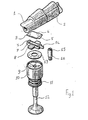
- - Fig. 1 is an exploded view of the tappet according to the invention;
- - Fig. 2 is a view of the device shown in Fig. 1 as inserted into the cylinder head.
- With reference to figures, (1) indicates a camshaft with variable-
profile cams 2 employed in an internal combustion engine to control valve opening and closing. - (3) shows a rectangular shoe with
flat surface 4 of shoe-cam contact. - The shoe at its lowest end exhibits a
circular section projection 5 coaxial to the major shoe centerline. - The above shoe rests with the
projection 5 in a semicircular seat 6 obtained on a shoe-holder saddle 7. - Such a matching allows the shoe to rotate around its longitudinal axis and to follow up the cam angular variations through the
contact area 4. - The shoe-
holder saddle 7 displays twofins 8 diametrically opposite on the largest saddle faces, in a central position, and suited to be housed into acircular seat 9 on the upper wall of the bucket 10, surrounding thespring 11 ofvalve 12. - In this way, the
saddle 7 is located against the bucket, which however is free to rotate around its centerline. - The
circular seat 9 is also used to insert the tappetplay adjustment discs 13. - The shoe-
holder saddle 7 is also fitted with anextension 14 coaxial to its major axis which is inserted in a sliding way into aslot 15 made on ascrew 16, the latter being secured to thecylinder head 17 near the slidingseat 18 of the bucket 10. - In this way, the
saddle 7, whose axis is perpendicular to theshaft 1 axis, is prevented from rotating. - The length of
slot 13 will be so calculated as not to compromise the tappet stroke at valve opening.
Claims (4)
characterized in
Applications Claiming Priority (2)
| Application Number | Priority Date | Filing Date | Title |
|---|---|---|---|
| IT6760485 | 1985-07-02 | ||
| IT67604/85A IT1182480B (en) | 1985-07-02 | 1985-07-02 | TAPPING SYSTEM FOR INTERNAL COMBUSTION ENGINES EQUIPPED WITH SHAFTS WITH VARIABLE PROFILE CAMS |
Publications (2)
| Publication Number | Publication Date |
|---|---|
| EP0208663A1 EP0208663A1 (en) | 1987-01-14 |
| EP0208663B1 true EP0208663B1 (en) | 1989-01-25 |
Family
ID=11303799
Family Applications (1)
| Application Number | Title | Priority Date | Filing Date |
|---|---|---|---|
| EP86830179A Expired EP0208663B1 (en) | 1985-07-02 | 1986-06-25 | Tappet system for internal combustion engines fitted with variable-profile camshafts |
Country Status (7)
| Country | Link |
|---|---|
| US (1) | US4693214A (en) |
| EP (1) | EP0208663B1 (en) |
| JP (1) | JPH0745803B2 (en) |
| BR (1) | BR8603228A (en) |
| DE (1) | DE3661955D1 (en) |
| ES (1) | ES8704584A1 (en) |
| IT (1) | IT1182480B (en) |
Families Citing this family (30)
| Publication number | Priority date | Publication date | Assignee | Title |
|---|---|---|---|---|
| DE3624612A1 (en) * | 1986-07-21 | 1988-02-04 | Mtu Friedrichshafen Gmbh | VALVE CONTROL FOR A PISTON PISTON COMBUSTION ENGINE |
| US4850311A (en) * | 1988-12-09 | 1989-07-25 | General Motors Corporation | Three dimensional cam cardanic follower valve lifter |
| US5048474A (en) * | 1989-02-22 | 1991-09-17 | Nissan Motor Co., Ltd. | Valve train for automotive engine |
| US5211143A (en) * | 1991-05-03 | 1993-05-18 | Ford Motor Company | Adjustable valve system for an internal combustion engine |
| US5159906A (en) * | 1991-05-03 | 1992-11-03 | Ford Motor Company | Adjustable valve system for an internal combustion engine |
| DE4230809C2 (en) * | 1992-09-02 | 1995-03-09 | Steckhan Helmut Prof Dr | Valve control for internal combustion engines |
| AUPN926596A0 (en) * | 1996-04-16 | 1996-05-09 | Roberts, Frederick William | Valve timing system |
| US5803033A (en) * | 1996-11-08 | 1998-09-08 | Toyota Jidosha Kabushiki Kaisha | Valve drive apparatus for an internal combustion engine having a convex shim between a cam and a valve |
| JPH10196333A (en) * | 1997-01-14 | 1998-07-28 | Toyota Motor Corp | Valve lifter structure |
| DE69806833T2 (en) | 1997-04-04 | 2003-04-10 | Toyota Motor Co Ltd | Three-dimensional cam and valve train device |
| JPH11200824A (en) * | 1998-01-20 | 1999-07-27 | Denso Corp | Variable valve control device |
| JPH11210433A (en) * | 1998-01-29 | 1999-08-03 | Denso Corp | Variable valve control device |
| JPH11218014A (en) | 1998-02-03 | 1999-08-10 | Toyota Motor Corp | Variable valve timing device |
| JP3539182B2 (en) | 1998-02-20 | 2004-07-07 | トヨタ自動車株式会社 | Variable valve timing device |
| JP2000073710A (en) * | 1998-08-31 | 2000-03-07 | Toyota Motor Corp | Swing follower mechanism of three-dimensional cam |
| JP3700409B2 (en) | 1998-09-04 | 2005-09-28 | トヨタ自動車株式会社 | 3D cam valve lifter and variable valve operating device |
| JP2000104570A (en) * | 1998-09-28 | 2000-04-11 | Toyota Motor Corp | Number of revolutions control device for internal combustion engine |
| US6318313B1 (en) | 1998-10-06 | 2001-11-20 | Toyota Jidosha Kabushiki Kaisha | Variable performance valve train having three-dimensional cam |
| US6425359B2 (en) * | 2000-06-23 | 2002-07-30 | Honda Giken Kogyo Kabushiki Kaisha | Valve moving apparatus of an internal combustion engine |
| DE10225721A1 (en) * | 2001-06-25 | 2003-01-09 | Ina Schaeffler Kg | Method for fitting valve guide bridge to engine head block using clip fastening into prepared holes in the block |
| DE102005021788B4 (en) * | 2005-05-11 | 2006-12-28 | Krüger, Hermann, Prof. Dr.-Ing. | Method and device for producing a three-dimensional cam and three-dimensional cams, in particular for the variable actuation of lift valves in internal combustion engines |
| DE102006047293A1 (en) * | 2006-10-06 | 2008-04-10 | Schaeffler Kg | Valve drive for an internal combustion engine with displaceable space cam |
| US8171906B2 (en) | 2008-10-21 | 2012-05-08 | Apq Development, Llc | Valve lifter guide and method of using same |
| DE102011106395A1 (en) | 2011-07-02 | 2013-01-03 | Man Truck & Bus Ag | Valve control for at least one valve of an internal combustion engine |
| CN103161538B (en) * | 2013-02-28 | 2015-04-22 | 长城汽车股份有限公司 | Variable valve lift driving device rocker mechanism used for engine |
| CN103147814B (en) * | 2013-02-28 | 2015-03-11 | 长城汽车股份有限公司 | Tappet mechanism for variable valve lift driving device of engine |
| EP2808503A1 (en) | 2013-05-27 | 2014-12-03 | FPT Motorenforschung AG | System for performing an engine braking procedure based on decompression events for a 4-stroke cycle engine |
| CN103352736A (en) * | 2013-07-11 | 2013-10-16 | 浙江大学 | Continuous variable valve lift mechanism |
| CN104279014B (en) * | 2014-08-04 | 2018-04-27 | 武汉东方骏驰精密制造有限公司 | New anti-rotation roller lifts tappet |
| CN113945307B (en) * | 2021-10-08 | 2023-07-21 | 哈尔滨工程大学 | Sensor and method for measuring contact force of cam tappet of engine |
Family Cites Families (13)
| Publication number | Priority date | Publication date | Assignee | Title |
|---|---|---|---|---|
| US1579850A (en) * | 1926-04-06 | Vaxve tappet | ||
| US905733A (en) * | 1908-04-27 | 1908-12-01 | Arthur J Miller | Internal-combustion engine. |
| US1100912A (en) * | 1913-07-19 | 1914-06-23 | Rich Tool Company | Valve-actuating device for internal-combustion engines. |
| US1123142A (en) * | 1914-05-11 | 1914-12-29 | Rich Tool Company | Valve-actuating device for internal-combustion engines. |
| US1413535A (en) * | 1919-02-24 | 1922-04-18 | Willys Overland Co | Automatic take-up device |
| US1613012A (en) * | 1924-06-20 | 1927-01-04 | Leslie M Baker | Valve mechanism |
| US2051313A (en) * | 1933-08-14 | 1936-08-18 | Boyle Motor Products Company | Valve attachment |
| FR1098374A (en) * | 1953-04-08 | 1955-07-25 | Albion Motors Ltd | Improvements to mechanical connection systems |
| SU775358A1 (en) * | 1977-05-04 | 1980-10-30 | Пензенский Дизельный Завод Производственного Объединения По Дизелям И Турбокомпрессорам | Gas distribution mechanism |
| FR2421273A1 (en) * | 1978-04-01 | 1979-10-26 | Daimler Benz Ag | INTERNAL COMBUSTION ENGINE WITH MULTIPLE CYLINDERS AND EQUIPPED WITH A VALVE DISCONNECTION SYSTEM |
| IT1156204B (en) * | 1982-10-12 | 1987-01-28 | Fiat Auto Spa | TAPPING SYSTEM FOR VERTICAL PROFILE CAMSHAFTS ENGINES |
| IT1159352B (en) * | 1983-02-04 | 1987-02-25 | Fiat Auto Spa | DEVICE FOR ADJUSTING THE AXIAL POSITION OF A VARIABLE PROFILE CAMSHAFT, PARTICULARLY FOR THE CONTROL OF THE DISTRIBUTION OF AN ENGINE |
| US4587934A (en) * | 1983-05-16 | 1986-05-13 | Moores Keith J | Variable-timing valve actuating mechanism |
-
1985
- 1985-07-02 IT IT67604/85A patent/IT1182480B/en active
-
1986
- 1986-06-23 ES ES556412A patent/ES8704584A1/en not_active Expired
- 1986-06-24 US US06/877,937 patent/US4693214A/en not_active Expired - Fee Related
- 1986-06-25 DE DE8686830179T patent/DE3661955D1/en not_active Expired
- 1986-06-25 EP EP86830179A patent/EP0208663B1/en not_active Expired
- 1986-07-01 JP JP61154928A patent/JPH0745803B2/en not_active Expired - Lifetime
- 1986-07-01 BR BR8603228A patent/BR8603228A/en unknown
Also Published As
| Publication number | Publication date |
|---|---|
| DE3661955D1 (en) | 1989-03-02 |
| IT1182480B (en) | 1987-10-05 |
| BR8603228A (en) | 1987-02-24 |
| JPH0745803B2 (en) | 1995-05-17 |
| ES8704584A1 (en) | 1987-04-01 |
| ES556412A0 (en) | 1987-04-01 |
| JPS627907A (en) | 1987-01-14 |
| US4693214A (en) | 1987-09-15 |
| IT8567604A0 (en) | 1985-07-02 |
| EP0208663A1 (en) | 1987-01-14 |
Similar Documents
| Publication | Publication Date | Title |
|---|---|---|
| EP0208663B1 (en) | Tappet system for internal combustion engines fitted with variable-profile camshafts | |
| EP0263794B1 (en) | Valve control for overhead camshaft engines | |
| EP0108238B1 (en) | Tappet for internal combustion engines with variable profile camshafts | |
| US4624222A (en) | Intake valve structure for internal combustion engine | |
| US4539953A (en) | Apparatus for actuating intake and exhaust valves in internal combustion engine | |
| US4617881A (en) | Actuating mechanism for multiple valve internal combustion engine | |
| EP0179581A2 (en) | Variable valve timing mechanism | |
| JPS60147510A (en) | Spring of end pivot type locker arm for internal-combustion engine moving valve system | |
| US4638774A (en) | Valve actuating mechanism for internal combustion engine | |
| US4637356A (en) | Valve actuating mechanism for internal combustion engine | |
| US4686945A (en) | Valve structure for an internal combustion engine | |
| US4885952A (en) | Cylindrical tappet | |
| US4911113A (en) | Valve actuating device for multiple valve type engine | |
| US6386159B1 (en) | Valve timing system | |
| US6422189B1 (en) | Mechanical lash control apparatus for an engine cam | |
| EP0252628B1 (en) | Fuel injection pump | |
| US3270726A (en) | Valve tappet | |
| US5931130A (en) | Desmodromic distribution system for four-stroke engines | |
| SU1114807A1 (en) | Cearance adjustment device | |
| FR2510647A1 (en) | Lever or cam bolt for lock - has direct fit to cylinder barrel on axial extension with engaging flats | |
| SU922296A1 (en) | Gas-distributing mechanism for i.c. engine with phase control | |
| JPS6121562Y2 (en) | ||
| JPH03121207A (en) | Valve-controlled internal combusion engine | |
| KR100235672B1 (en) | Automatic adjusting device of valve clearance of internal combustion engine | |
| KR100501461B1 (en) | Valve timing system |
Legal Events
| Date | Code | Title | Description |
|---|---|---|---|
| PUAI | Public reference made under article 153(3) epc to a published international application that has entered the european phase |
Free format text: ORIGINAL CODE: 0009012 |
|
| AK | Designated contracting states |
Kind code of ref document: A1 Designated state(s): BE DE FR GB NL SE |
|
| 17P | Request for examination filed |
Effective date: 19870225 |
|
| 17Q | First examination report despatched |
Effective date: 19871222 |
|
| GRAA | (expected) grant |
Free format text: ORIGINAL CODE: 0009210 |
|
| AK | Designated contracting states |
Kind code of ref document: B1 Designated state(s): BE DE FR GB NL SE |
|
| REF | Corresponds to: |
Ref document number: 3661955 Country of ref document: DE Date of ref document: 19890302 |
|
| ET | Fr: translation filed | ||
| PLBE | No opposition filed within time limit |
Free format text: ORIGINAL CODE: 0009261 |
|
| STAA | Information on the status of an ep patent application or granted ep patent |
Free format text: STATUS: NO OPPOSITION FILED WITHIN TIME LIMIT |
|
| 26N | No opposition filed | ||
| EAL | Se: european patent in force in sweden |
Ref document number: 86830179.7 |
|
| PGFP | Annual fee paid to national office [announced via postgrant information from national office to epo] |
Ref country code: SE Payment date: 19960509 Year of fee payment: 11 |
|
| PGFP | Annual fee paid to national office [announced via postgrant information from national office to epo] |
Ref country code: GB Payment date: 19960617 Year of fee payment: 11 |
|
| PGFP | Annual fee paid to national office [announced via postgrant information from national office to epo] |
Ref country code: FR Payment date: 19960627 Year of fee payment: 11 |
|
| PGFP | Annual fee paid to national office [announced via postgrant information from national office to epo] |
Ref country code: DE Payment date: 19960830 Year of fee payment: 11 |
|
| PG25 | Lapsed in a contracting state [announced via postgrant information from national office to epo] |
Ref country code: GB Free format text: LAPSE BECAUSE OF NON-PAYMENT OF DUE FEES Effective date: 19970625 |
|
| PG25 | Lapsed in a contracting state [announced via postgrant information from national office to epo] |
Ref country code: SE Effective date: 19970626 |
|
| PGFP | Annual fee paid to national office [announced via postgrant information from national office to epo] |
Ref country code: NL Payment date: 19970630 Year of fee payment: 12 |
|
| GBPC | Gb: european patent ceased through non-payment of renewal fee |
Effective date: 19970625 |
|
| PG25 | Lapsed in a contracting state [announced via postgrant information from national office to epo] |
Ref country code: FR Free format text: LAPSE BECAUSE OF NON-PAYMENT OF DUE FEES Effective date: 19980227 |
|
| EUG | Se: european patent has lapsed |
Ref document number: 86830179.7 |
|
| PG25 | Lapsed in a contracting state [announced via postgrant information from national office to epo] |
Ref country code: DE Free format text: LAPSE BECAUSE OF NON-PAYMENT OF DUE FEES Effective date: 19980303 |
|
| REG | Reference to a national code |
Ref country code: FR Ref legal event code: ST |
|
| REG | Reference to a national code |
Ref country code: FR Ref legal event code: ST |
|
| PGFP | Annual fee paid to national office [announced via postgrant information from national office to epo] |
Ref country code: BE Payment date: 19980813 Year of fee payment: 13 |
|
| PG25 | Lapsed in a contracting state [announced via postgrant information from national office to epo] |
Ref country code: NL Free format text: LAPSE BECAUSE OF NON-PAYMENT OF DUE FEES Effective date: 19990101 |
|
| NLV4 | Nl: lapsed or anulled due to non-payment of the annual fee |
Effective date: 19990101 |
|
| PG25 | Lapsed in a contracting state [announced via postgrant information from national office to epo] |
Ref country code: BE Free format text: LAPSE BECAUSE OF NON-PAYMENT OF DUE FEES Effective date: 19990630 |
|
| BERE | Be: lapsed |
Owner name: FIAT AUTO S.P.A. Effective date: 19990630 |