EP0209752A1 - Portable thermal printer - Google Patents
Portable thermal printer Download PDFInfo
- Publication number
- EP0209752A1 EP0209752A1 EP86108662A EP86108662A EP0209752A1 EP 0209752 A1 EP0209752 A1 EP 0209752A1 EP 86108662 A EP86108662 A EP 86108662A EP 86108662 A EP86108662 A EP 86108662A EP 0209752 A1 EP0209752 A1 EP 0209752A1
- Authority
- EP
- European Patent Office
- Prior art keywords
- thermal
- printer
- label
- labels
- data
- Prior art date
- Legal status (The legal status is an assumption and is not a legal conclusion. Google has not performed a legal analysis and makes no representation as to the accuracy of the status listed.)
- Withdrawn
Links
Images


Classifications
-
- G—PHYSICS
- G06—COMPUTING; CALCULATING OR COUNTING
- G06K—GRAPHICAL DATA READING; PRESENTATION OF DATA; RECORD CARRIERS; HANDLING RECORD CARRIERS
- G06K7/00—Methods or arrangements for sensing record carriers, e.g. for reading patterns
- G06K7/10—Methods or arrangements for sensing record carriers, e.g. for reading patterns by electromagnetic radiation, e.g. optical sensing; by corpuscular radiation
- G06K7/10544—Methods or arrangements for sensing record carriers, e.g. for reading patterns by electromagnetic radiation, e.g. optical sensing; by corpuscular radiation by scanning of the records by radiation in the optical part of the electromagnetic spectrum
- G06K7/10821—Methods or arrangements for sensing record carriers, e.g. for reading patterns by electromagnetic radiation, e.g. optical sensing; by corpuscular radiation by scanning of the records by radiation in the optical part of the electromagnetic spectrum further details of bar or optical code scanning devices
- G06K7/10881—Methods or arrangements for sensing record carriers, e.g. for reading patterns by electromagnetic radiation, e.g. optical sensing; by corpuscular radiation by scanning of the records by radiation in the optical part of the electromagnetic spectrum further details of bar or optical code scanning devices constructional details of hand-held scanners
-
- B—PERFORMING OPERATIONS; TRANSPORTING
- B41—PRINTING; LINING MACHINES; TYPEWRITERS; STAMPS
- B41J—TYPEWRITERS; SELECTIVE PRINTING MECHANISMS, i.e. MECHANISMS PRINTING OTHERWISE THAN FROM A FORME; CORRECTION OF TYPOGRAPHICAL ERRORS
- B41J3/00—Typewriters or selective printing or marking mechanisms characterised by the purpose for which they are constructed
- B41J3/36—Typewriters or selective printing or marking mechanisms characterised by the purpose for which they are constructed for portability, i.e. hand-held printers or laptop printers
-
- B—PERFORMING OPERATIONS; TRANSPORTING
- B65—CONVEYING; PACKING; STORING; HANDLING THIN OR FILAMENTARY MATERIAL
- B65C—LABELLING OR TAGGING MACHINES, APPARATUS, OR PROCESSES
- B65C11/00—Manually-controlled or manually-operable label dispensers, e.g. modified for the application of labels to articles
- B65C11/02—Manually-controlled or manually-operable label dispensers, e.g. modified for the application of labels to articles having printing equipment
- B65C11/0289—Manually-controlled or manually-operable label dispensers, e.g. modified for the application of labels to articles having printing equipment using electrical or electro-mechanical means
-
- B—PERFORMING OPERATIONS; TRANSPORTING
- B65—CONVEYING; PACKING; STORING; HANDLING THIN OR FILAMENTARY MATERIAL
- B65C—LABELLING OR TAGGING MACHINES, APPARATUS, OR PROCESSES
- B65C2210/00—Details of manually controlled or manually operable label dispensers
- B65C2210/0002—Data entry devices
- B65C2210/0005—Readers
- B65C2210/0008—Optical scanners
-
- B—PERFORMING OPERATIONS; TRANSPORTING
- B65—CONVEYING; PACKING; STORING; HANDLING THIN OR FILAMENTARY MATERIAL
- B65C—LABELLING OR TAGGING MACHINES, APPARATUS, OR PROCESSES
- B65C2210/00—Details of manually controlled or manually operable label dispensers
- B65C2210/0002—Data entry devices
- B65C2210/0013—Keyboards; Touchscreens
- B65C2210/0018—Keyboards; Touchscreens permanent
-
- B—PERFORMING OPERATIONS; TRANSPORTING
- B65—CONVEYING; PACKING; STORING; HANDLING THIN OR FILAMENTARY MATERIAL
- B65C—LABELLING OR TAGGING MACHINES, APPARATUS, OR PROCESSES
- B65C2210/00—Details of manually controlled or manually operable label dispensers
- B65C2210/0002—Data entry devices
- B65C2210/0024—Hosts
-
- Y—GENERAL TAGGING OF NEW TECHNOLOGICAL DEVELOPMENTS; GENERAL TAGGING OF CROSS-SECTIONAL TECHNOLOGIES SPANNING OVER SEVERAL SECTIONS OF THE IPC; TECHNICAL SUBJECTS COVERED BY FORMER USPC CROSS-REFERENCE ART COLLECTIONS [XRACs] AND DIGESTS
- Y10—TECHNICAL SUBJECTS COVERED BY FORMER USPC
- Y10T—TECHNICAL SUBJECTS COVERED BY FORMER US CLASSIFICATION
- Y10T156/00—Adhesive bonding and miscellaneous chemical manufacture
- Y10T156/17—Surface bonding means and/or assemblymeans with work feeding or handling means
- Y10T156/1788—Work traversing type and/or means applying work to wall or static structure
- Y10T156/1795—Implement carried web supply
Definitions
- This invention relates to a portable thermal label printer employing an optical reading means such as a pen scanner or touch scanner as data input means, and more particularly to a portable thermal label printer which has improved portability and operability for when operation is being done while various articles of freight are being handled.
- thermal label printers which is light and easy to use. It is of course also preferable that thermal label printers in use at retailers have good portability and operability.
- the thermal label strip T paid out from the thermal label roll R is printed between a thermal print head 20 and a platen 21, and at a bending pin 16 the backing sheet S alone is redirected so that a label L is discharged from the printer unit, and the backing sheet S is moved by engagement with the conveyor roller 19, to be discharged from the rear of the unit.
- the thermal print head 20 is driven and controlled by a control circuit 26 which is connected to a battery 27.
- the thermal label strip T crosses a flat cable C that is used to connect the control circuit 26 with the thermal print head 20, forming an intersection K. Because of this, it is necessary to, for example, divide the flat cable C so that it goes to the left and right of the thermal label strip T.
- Such a structure has required that the printer be designed broader, and the unavoidable result has been that, overall, the thermal label printer becomes larger or heavier.
- An object of the present invention is to provide a portable thermal label printer which can be operated easily to print labels even while relatively large articles of freight are being handled.
- the present invention attains this object by providing a portable thermal label printer whereby the only portion that is held in the hand is the optical scanning means, such as a pen scanner or touch scanner, and which is light and easy to operate, and the printing and other mechanisms can be arranged about the person, freeing the operator's hands and thereby improving work efficiency, while at the same time, by eliminating the intersection between the thermal print head flat cable and the thermal label strip, enables the printer to be made smaller overall.
- the optical scanning means such as a pen scanner or touch scanner
- the main unit 2 of a printer constructed for portability has a side surface 3 for contacting a desired part of a person's body, such as for example the waist W of an operator.
- the side surface 3 is provided with feet 3a formed of rubber or the like, so as to enable the printer to be set on any desired surface for use as a desk-top type printing unit.
- the main unit 2 is also provided with a shoulder carrying means 2a to enable the main unit 2 to be carried from the shoulder as well as about the waist.
- a belt or the like may also be used to enable the main unit 2 to be provided about the waist W.
- the main unit 2 is provided on its top surface with data and command entry means consisting of a keyboard 6 comprising a numeric pad 4 and various function keys 5, and at a position above the keyboard with a display 7 such as a liquid crystal display, for example.
- the main unit 2 is also provided with a power switch 8 on one side.
- the main unit 2 is further provided at a lower portion with a support member 10 for holding a thermal label roll R which consists of a thermal label strip T wound into a roll, the arrangement being such that after labels L are printed and detached the labels L are discharged from slightly below the upper surface portion of the main unit 2.
- a socket 12a for connecting a pen scanner 11 and a socket 13 for connecting a battery 27, which will be described later, to a battery charger.
- the numeral 14 denotes the discharge outlet for the backing sheet S.
- the pen scanner 11 can be used to read a slip number bar code B on a label F already affixed to a box or other article of freight (not shown) for input of such data into the printer 1.
- the thermal label strip T passes from the thermal label roll R on the support member 10 into a label strip passage 18 via a position sensor 15.
- the label strip T consists of a backing sheet S coated with a separating agent and having a plurality of labels L, each of which is coated with an adhesive, detachably adhered continuously along its length.
- a slip code I which corresponds to the bar code B and other information I on the tag F
- the backing sheet S is provided with holes D which are for position detection purposes.
- the holes D can also be utilized for conveyance purposes by engagement with the conveyor roller 19 ( Figure 1).
- the thermal label strip T passes via the conveyor roller 19 to a thermal print head 20 and a platen 21, is redirected at the platen 21 portion, where the labels L are peeled off, so that 'just the backing sheet S is directed back to engagement with the conveyor roller 19, and the backing sheet S then feeds out from the main unit 2 via the discharge outlet 14.
- the conveyor roller 19 is driven by the stepped rotation action of a stepping motor M so as to move the thermal label strip T in the required direction for printing and conveyance.
- the thermal label strip T may also be fed out of the main unit 2 as is, without the peeling, after it has been passed between the thermal print head 20 and the platen 21.
- the thermal print head 20 may be separated from the platen 21 as indicated by the arrow.
- the main unit 2 houses a control circuit 26 which is connected to the battery 27, an interface 28 for data input from and output to external devices, a ROM program memory 29 for communication and control programs, a RAM data memory 30, and the keyboard 6.
- the display 7, sensor 15, thermal print head 20 and stepping motor M are also connected to and controlled by the control circuit 26.
- the battery 27 is a rechargeable type and can be connected via the socket 13 to an external battery charger (not shown).
- Figure ⁇ 3 shows the thermal printer connected to a microcomputer 32 to allow data I/O operations therebetween. Data can be transferred to the microcomputer 32 via the socket 12 of the interface 28 and a cable 33.
- an acoustic coupler may also be used to link the printer 1 to a host computer via telephone by means of a wired or wireless link (this is not illustrated).
- the operator carries the printer at his waist or hung from the shoulder by means of a belt or shoulder carrying means 2a. This leaves the operator's hands free of the printer 1, with only the very light pen scanner 11 needing to be held in one hand to operate the unit. Therefore, if the operator usually leaves the pen scanner 11 in a breast pocket or the like, he can have both hands free to deal with articles of freight. Thus, the freight items can be dealt with and labels printed out with none of the operational inconvenience of the conventional label printers.
- the operator uses the pen scanner 11 to read the bar code B of the tags F which have already been stuck on the articles of freight (which are usually in cardboard boxes).
- the read data is stored in a data memory 30, and upon a print command signal being issued by the control circuit 26, information having the same kind of content as that of the tags -F is printed on the labels L in accordance with the said data.
- one of the function keys 5 is a print button (not shown), and when the print button is pressed the conveyor roller 19 rotates, moving the thermal label strip T, so that at the thermal print head 20 the required bar code B can be printed on the label L in accordance with a print pattern, and as the backing sheet S alone is redirected at the platen 21 the labels L are peeled from the backing sheet S and discharged from the main unit 2.
- control may be effected whereby the printing is carried out immediately following completion of the reading operation by the pen scanner 11.
- keyboard 6 can be employed for data input rather than the pen scanner 11. Input data can be displayed on the display 7 for confirmation purposes.
- the data memory 30 When data input by means of the pen scanner 11 or the keyboard 6 has been temporarily stored in the data memory 30, it can if required be uploaded to the microcomputer 32 or a host computer, as shown in Figure 3, by means of the interface 28 and the socket 12, for processing.
- the socket 12 can also be used for inputting data into the printer from other external devices.
- the printer according to this invention is widely applicable when labels have to be printed in accordance with various types of data transaction, applications which could not be handled by conventional printers.
- Some of the potential applications for the present thermal printer include inventory control of retail outlets, management of business data files, printing of blood data cards and sample tube labels at blood banks, printing of bar code labels for patient charts and medical certificates at hospitals and clinics, process, parts and inventory control in factories, and the management of customer data, and data and printing of labels relating to outside suppliers at department stores and supermarkets.
- the support member 10 of the thermal label roll R is provided on the heating-surface side of the thermal print head 20, so there is no intersection of the flat cable C and the thermal label strip T. This enables the overall design to be made more compact, which is also desirable as compactness is highly important in terms of portability.
- the operator only has to hold the pen scanner or whatever optical scanning means is used, and therefore use both hands to handle articles of freight. Therefore, it enables freight to be handled and labels printed efficiently.
- the arrangement of the thermal label roll and thermal printing means is such that the overall unit can be easily made more compact, enabling a printer to be provided that is light and has good operability.
Abstract
A printer (1) employs an optical reading means (11) such as a pen scanner or touch scanner as data input means. and the operator only has to hold the pen scanner or whatever optical scanning means is used, the other parts being held around the operator's waist (W) or the like. Therefore, the operator can use both hands to handle articles of freight, such as boxes, therefore enabling freight to be handled and labels printed easily and efficiently. In addition, the arrangement of the thermal label roll (R) and thermal printing means (20) enables the overall unit to be made more light and compact.
Description
- This invention relates to a portable thermal label printer employing an optical reading means such as a pen scanner or touch scanner as data input means, and more particularly to a portable thermal label printer which has improved portability and operability for when operation is being done while various articles of freight are being handled.
- With the conventional portable thermal label printers in use at supermarkets and other such retail outlets, the whole printer has to be held in the hand and used like a hammer in order to have the printed labels peeled off and applied to the merchandise.
- At retail outlets the individual items of merchandise are not so large, and so such printers can be used while manipulating the merchandise even if the printer is on the heavy side. However, in the freight business where various articles of freight and boxes have to be handled, there has been a need for a thermal label printer which is light and easy to use. It is of course also preferable that thermal label printers in use at retailers have good portability and operability.
- However, because of the weight of the batteries used for driving and the other parts and components, it has been hard to realize a portable thermal label printer which could be operated while being hand-held, was light and had good operability.
- In addition, with the label printer/applicators commonly referred to as hand labelers, the design concept generally adhered to called for the thermal label roll to be positioned at the top of the labeler, which led to the following type of problems.
- With reference to Figure 4, the thermal label strip T paid out from the thermal label roll R is printed between a
thermal print head 20 and aplaten 21, and at abending pin 16 the backing sheet S alone is redirected so that a label L is discharged from the printer unit, and the backing sheet S is moved by engagement with theconveyor roller 19, to be discharged from the rear of the unit. Thethermal print head 20 is driven and controlled by acontrol circuit 26 which is connected to abattery 27. - However, in the arrangement as shown in the figure, the thermal label strip T crosses a flat cable C that is used to connect the
control circuit 26 with thethermal print head 20, forming an intersection K. Because of this, it is necessary to, for example, divide the flat cable C so that it goes to the left and right of the thermal label strip T. Such a structure has required that the printer be designed broader, and the unavoidable result has been that, overall, the thermal label printer becomes larger or heavier. - An object of the present invention is to provide a portable thermal label printer which can be operated easily to print labels even while relatively large articles of freight are being handled.
- The present invention attains this object by providing a portable thermal label printer whereby the only portion that is held in the hand is the optical scanning means, such as a pen scanner or touch scanner, and which is light and easy to operate, and the printing and other mechanisms can be arranged about the person, freeing the operator's hands and thereby improving work efficiency, while at the same time, by eliminating the intersection between the thermal print head flat cable and the thermal label strip, enables the printer to be made smaller overall.
-
- Figure 1 is a sectional side view of the portable thermal label printer according to this invention;
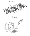
- Figure 2 is a perspective view of a segment of the label strip;
- Figure 3 is a view illustrating the printer connected to a microcomputer;
- Figure 4 is an outline view of a conventional portable thermal label printer; and
- Figure 5 is a view of the principal portions in the vicinity of the thermal print head.
- With reference to Figure 1, the
main unit 2 of a printer constructed for portability has aside surface 3 for contacting a desired part of a person's body, such as for example the waist W of an operator. Theside surface 3 is provided withfeet 3a formed of rubber or the like, so as to enable the printer to be set on any desired surface for use as a desk-top type printing unit. Themain unit 2 is also provided with ashoulder carrying means 2a to enable themain unit 2 to be carried from the shoulder as well as about the waist. A belt or the like may also be used to enable themain unit 2 to be provided about the waist W. - The
main unit 2 is provided on its top surface with data and command entry means consisting of akeyboard 6 comprising anumeric pad 4 andvarious function keys 5, and at a position above the keyboard with adisplay 7 such as a liquid crystal display, for example. Themain unit 2 is also provided with apower switch 8 on one side. Themain unit 2 is further provided at a lower portion with asupport member 10 for holding a thermal label roll R which consists of a thermal label strip T wound into a roll, the arrangement being such that after labels L are printed and detached the labels L are discharged from slightly below the upper surface portion of themain unit 2. - At the rear end of the
main unit 2 are provided a socket 12a for connecting apen scanner 11 and asocket 13 for connecting abattery 27, which will be described later, to a battery charger. Thenumeral 14 denotes the discharge outlet for the backing sheet S. Thepen scanner 11 can be used to read a slip number bar code B on a label F already affixed to a box or other article of freight (not shown) for input of such data into theprinter 1. - The internal structure of the
printer 1 will now be explained. The thermal label strip T passes from the thermal label roll R on thesupport member 10 into alabel strip passage 18 via aposition sensor 15. - As shown in Figure 2, the label strip T consists of a backing sheet S coated with a separating agent and having a plurality of labels L, each of which is coated with an adhesive, detachably adhered continuously along its length. On the labels L of the thermal label strip T is printed a slip code I which corresponds to the bar code B and other information I on the tag F, and the backing sheet S is provided with holes D which are for position detection purposes. The holes D can also be utilized for conveyance purposes by engagement with the conveyor roller 19 (Figure 1). Reverting to Figure 1, the thermal label strip T passes via the
conveyor roller 19 to athermal print head 20 and aplaten 21, is redirected at theplaten 21 portion, where the labels L are peeled off, so that 'just the backing sheet S is directed back to engagement with theconveyor roller 19, and the backing sheet S then feeds out from themain unit 2 via thedischarge outlet 14. Theconveyor roller 19 is driven by the stepped rotation action of a stepping motor M so as to move the thermal label strip T in the required direction for printing and conveyance. - In the embodiment shown in the figure the label L is peeled off, but the thermal label strip T may also be fed out of the
main unit 2 as is, without the peeling, after it has been passed between thethermal print head 20 and theplaten 21. Regarding the insertion of the label strip T, thethermal print head 20 may be separated from theplaten 21 as indicated by the arrow. - The
main unit 2 houses acontrol circuit 26 which is connected to thebattery 27, aninterface 28 for data input from and output to external devices, aROM program memory 29 for communication and control programs, aRAM data memory 30, and thekeyboard 6. Thedisplay 7,sensor 15,thermal print head 20 and stepping motor M are also connected to and controlled by thecontrol circuit 26. Thebattery 27 is a rechargeable type and can be connected via thesocket 13 to an external battery charger (not shown). - Figure`3 shows the thermal printer connected to a
microcomputer 32 to allow data I/O operations therebetween. Data can be transferred to themicrocomputer 32 via thesocket 12 of theinterface 28 and acable 33. In addition, an acoustic coupler may also be used to link theprinter 1 to a host computer via telephone by means of a wired or wireless link (this is not illustrated). - The operation of the present invention will now be explained with reference to an example application of labels during the handling of articles of freight in the freight business.
- The operator carries the printer at his waist or hung from the shoulder by means of a belt or
shoulder carrying means 2a. This leaves the operator's hands free of theprinter 1, with only the verylight pen scanner 11 needing to be held in one hand to operate the unit. Therefore, if the operator usually leaves thepen scanner 11 in a breast pocket or the like, he can have both hands free to deal with articles of freight. Thus, the freight items can be dealt with and labels printed out with none of the operational inconvenience of the conventional label printers. - The operator uses the
pen scanner 11 to read the bar code B of the tags F which have already been stuck on the articles of freight (which are usually in cardboard boxes). The read data is stored in adata memory 30, and upon a print command signal being issued by thecontrol circuit 26, information having the same kind of content as that of the tags -F is printed on the labels L in accordance with the said data. Specifically, one of thefunction keys 5 is a print button (not shown), and when the print button is pressed theconveyor roller 19 rotates, moving the thermal label strip T, so that at thethermal print head 20 the required bar code B can be printed on the label L in accordance with a print pattern, and as the backing sheet S alone is redirected at theplaten 21 the labels L are peeled from the backing sheet S and discharged from themain unit 2. Instead of using the said print button, control may be effected whereby the printing is carried out immediately following completion of the reading operation by thepen scanner 11. - When many articles of freight have to be processed for dispatch, labels L thus printed and peeled may be taken and stuck on the freight by hand. Also, the
keyboard 6 can be employed for data input rather than thepen scanner 11. Input data can be displayed on thedisplay 7 for confirmation purposes. - When data input by means of the
pen scanner 11 or thekeyboard 6 has been temporarily stored in thedata memory 30, it can if required be uploaded to themicrocomputer 32 or a host computer, as shown in Figure 3, by means of theinterface 28 and thesocket 12, for processing. Thesocket 12 can also be used for inputting data into the printer from other external devices. - Thus, the printer according to this invention is widely applicable when labels have to be printed in accordance with various types of data transaction, applications which could not be handled by conventional printers.
- Some of the potential applications for the present thermal printer include inventory control of retail outlets, management of business data files, printing of blood data cards and sample tube labels at blood banks, printing of bar code labels for patient charts and medical certificates at hospitals and clinics, process, parts and inventory control in factories, and the management of customer data, and data and printing of labels relating to outside suppliers at department stores and supermarkets.
- As shown in Figure 1, the
support member 10 of the thermal label roll R is provided on the heating-surface side of thethermal print head 20, so there is no intersection of the flat cable C and the thermal label strip T. This enables the overall design to be made more compact, which is also desirable as compactness is highly important in terms of portability. - Thus, with the portable thermal label printer according to this invention the operator only has to hold the pen scanner or whatever optical scanning means is used, and therefore use both hands to handle articles of freight. Therefore, it enables freight to be handled and labels printed efficiently. In addition, the arrangement of the thermal label roll and thermal printing means is such that the overall unit can be easily made more compact, enabling a printer to be provided that is light and has good operability.
Claims (1)
1. A portable thermal label printer comprising a label printer unit having a path for the passage of a label strip consisting of thermosensitive labels detachably attached to a backing sheet, a supporting member for supporting a roll of label strip, thermal label position detecting means, a thermal label strip transport means, a thermal printing means for thermal character printing on the thermal labels, a data memory means, a data input means, a program memory means, an input/output means for data communication with external devices, and a control means for controlling the aforesaid means;
wherein the said data input means is a portable optical reader and the printer unit is provided with a means enabling the printer unit to be carried about the human body, and the said support member is located on the side on which the heating-surface of the thermal print head of the said thermal print means is located.
wherein the said data input means is a portable optical reader and the printer unit is provided with a means enabling the printer unit to be carried about the human body, and the said support member is located on the side on which the heating-surface of the thermal print head of the said thermal print means is located.
Applications Claiming Priority (2)
| Application Number | Priority Date | Filing Date | Title |
|---|---|---|---|
| JP60137858A JPS624045A (en) | 1985-06-26 | 1985-06-26 | Portable thermal label printer |
| JP137858/85 | 1985-06-26 |
Publications (1)
| Publication Number | Publication Date |
|---|---|
| EP0209752A1 true EP0209752A1 (en) | 1987-01-28 |
Family
ID=15208408
Family Applications (1)
| Application Number | Title | Priority Date | Filing Date |
|---|---|---|---|
| EP86108662A Withdrawn EP0209752A1 (en) | 1985-06-26 | 1986-06-25 | Portable thermal printer |
Country Status (5)
| Country | Link |
|---|---|
| US (1) | US4706095A (en) |
| EP (1) | EP0209752A1 (en) |
| JP (1) | JPS624045A (en) |
| CA (1) | CA1259852A (en) |
| DE (1) | DE209752T1 (en) |
Cited By (7)
| Publication number | Priority date | Publication date | Assignee | Title |
|---|---|---|---|---|
| EP0250910A2 (en) * | 1986-06-10 | 1988-01-07 | Kabushiki Kaisha Sato | Electronic hand labeller |
| EP0354814A2 (en) * | 1988-08-12 | 1990-02-14 | ESSELTE METO INTERNATIONAL GmbH | Printers and ancillary systems |
| GB2227460A (en) * | 1989-01-11 | 1990-08-01 | Monarch Marking Systems Inc | Label printing apparatus. |
| US5149211A (en) * | 1988-08-12 | 1992-09-22 | Pettigrew Robert M | Printers and ancillary systems |
| EP0571734A1 (en) * | 1992-03-27 | 1993-12-01 | Monarch Marking Systems, Inc. | Programmable hand held labeler |
| WO1997006497A1 (en) * | 1995-08-07 | 1997-02-20 | Raychem Limited | Producing marker sleeves |
| CN109533539A (en) * | 2018-12-29 | 2019-03-29 | 广州浩崎电子科技有限公司 | Labelling machine with stamp function |
Families Citing this family (33)
| Publication number | Priority date | Publication date | Assignee | Title |
|---|---|---|---|---|
| JP2551410B2 (en) * | 1986-06-10 | 1996-11-06 | 株式会社 サト− | Electronic handler bella |
| US4727245A (en) * | 1986-10-14 | 1988-02-23 | Mars, Inc. | Portable data scanner with removable modular printer |
| GB2206432B (en) * | 1987-05-20 | 1991-07-24 | Furuno Electric Co | Bar code printing and/or reading apparatus |
| US5448046A (en) * | 1987-12-28 | 1995-09-05 | Symbol Technologies, Inc. | Arrangement for and method of expediting commercial product transactions at a point-of-sale site |
| FR2626397B1 (en) * | 1988-01-22 | 1990-05-18 | Dassault Electronique | METHOD AND DEVICE FOR PRINTING LUGGAGE LABELS, PARTICULARLY FOR AIR TRANSPORT AND LABELS OBTAINED |
| US5111216A (en) * | 1988-07-12 | 1992-05-05 | Kroy Inc. | Tape supply cartridge for portable thermal printer |
| GB2223455A (en) * | 1988-08-12 | 1990-04-11 | Scient Generics Ltd | Thermal printing |
| US5028934A (en) * | 1988-10-31 | 1991-07-02 | Seiko Epson Corporation | Hand-held portable printing system |
| JPH0336843U (en) * | 1989-08-24 | 1991-04-10 | ||
| US5166498A (en) * | 1989-09-20 | 1992-11-24 | Neeley William E | Procedure and assembly for drawing blood |
| US5227617A (en) * | 1989-12-28 | 1993-07-13 | Monarch Marking Systems, Inc. | Hand-held label applicator with scanned data acquistion and selective data retrieval acquistion |
| US5294782A (en) * | 1991-09-27 | 1994-03-15 | Khyber Technologies Corporation | Integrated portable device for point of sale transactions |
| US5447380A (en) * | 1992-06-01 | 1995-09-05 | Nai Technologies, Inc. | Thermal printer |
| FR2696416B1 (en) † | 1992-10-07 | 1994-11-04 | Neopost Ind | Self-adhesive label tape and automatic label dispenser. |
| US5395181A (en) * | 1993-05-10 | 1995-03-07 | Microcom Corporation | Method and apparatus for printing a circular or bullseye bar code with a thermal printer |
| JPH07114630A (en) * | 1993-10-19 | 1995-05-02 | Matsushita Electric Ind Co Ltd | Small-sized information terminal device with image processing function |
| JPH07214826A (en) * | 1994-01-28 | 1995-08-15 | Casio Comput Co Ltd | Printing device |
| US5602377A (en) * | 1995-03-01 | 1997-02-11 | Metanetics Corporation | Bar code dataform scanning and labeling apparatus and method |
| US7468139B2 (en) | 1997-07-15 | 2008-12-23 | Silverbrook Research Pty Ltd | Method of depositing heater material over a photoresist scaffold |
| US6648453B2 (en) | 1997-07-15 | 2003-11-18 | Silverbrook Research Pty Ltd | Ink jet printhead chip with predetermined micro-electromechanical systems height |
| US6855264B1 (en) | 1997-07-15 | 2005-02-15 | Kia Silverbrook | Method of manufacture of an ink jet printer having a thermal actuator comprising an external coil spring |
| US6935724B2 (en) | 1997-07-15 | 2005-08-30 | Silverbrook Research Pty Ltd | Ink jet nozzle having actuator with anchor positioned between nozzle chamber and actuator connection point |
| US7556356B1 (en) | 1997-07-15 | 2009-07-07 | Silverbrook Research Pty Ltd | Inkjet printhead integrated circuit with ink spread prevention |
| US6712453B2 (en) | 1997-07-15 | 2004-03-30 | Silverbrook Research Pty Ltd. | Ink jet nozzle rim |
| US7195339B2 (en) | 1997-07-15 | 2007-03-27 | Silverbrook Research Pty Ltd | Ink jet nozzle assembly with a thermal bend actuator |
| US7337532B2 (en) | 1997-07-15 | 2008-03-04 | Silverbrook Research Pty Ltd | Method of manufacturing micro-electromechanical device having motion-transmitting structure |
| US7465030B2 (en) | 1997-07-15 | 2008-12-16 | Silverbrook Research Pty Ltd | Nozzle arrangement with a magnetic field generator |
| US6641315B2 (en) * | 1997-07-15 | 2003-11-04 | Silverbrook Research Pty Ltd | Keyboard |
| US6682174B2 (en) | 1998-03-25 | 2004-01-27 | Silverbrook Research Pty Ltd | Ink jet nozzle arrangement configuration |
| US7040822B2 (en) * | 2003-06-04 | 2006-05-09 | Hellermanntyton Corporation | Portable printing system |
| EP2769850A3 (en) | 2004-11-30 | 2016-04-13 | Panduit Corporation | Market-based labeling systems and method |
| US7971620B2 (en) * | 2007-12-28 | 2011-07-05 | Drummond Frederick J | Label producing message center and personal shopping device |
| US8851136B1 (en) * | 2013-03-13 | 2014-10-07 | Alexander V. Drynkin | Laboratory tube printer and labeler |
Citations (3)
| Publication number | Priority date | Publication date | Assignee | Title |
|---|---|---|---|---|
| GB2134679A (en) * | 1980-02-29 | 1984-08-15 | Symbol Technologies Inc | Light beam scanning device for scanning bar code symbols in laser scanning systems |
| US4497682A (en) * | 1981-05-29 | 1985-02-05 | Monarch Marking Systems, Inc. | Hand-held electrically selectable labeler |
| US4516016A (en) * | 1982-09-24 | 1985-05-07 | Kodron Rudolf S | Apparatus for recording and processing guest orders in restaurants or the like |
Family Cites Families (8)
| Publication number | Priority date | Publication date | Assignee | Title |
|---|---|---|---|---|
| JPS6016669B2 (en) * | 1978-07-26 | 1985-04-26 | シャープ株式会社 | Data transfer method |
| US4268179A (en) * | 1979-10-29 | 1981-05-19 | E. I. Du Pont De Nemours And Company | Method and system for reproducing identification characters |
| US4544287A (en) * | 1980-02-09 | 1985-10-01 | Teraoka Seikosho Co., Ltd. | Printing control apparatus for a label printer, method of using the apparatus, and a label used in conjunction with the apparatus |
| US4569421A (en) * | 1980-11-17 | 1986-02-11 | Sandstedt Gary O | Restaurant or retail vending facility |
| JPS57114438A (en) * | 1980-12-29 | 1982-07-16 | Sato Co Ltd | Label printing pasting device |
| US4578140A (en) * | 1981-07-21 | 1986-03-25 | Teraoka Seiko Co., Ltd. | Cassette type labeler and cassette case |
| JPH0620280B2 (en) * | 1981-07-22 | 1994-03-16 | 日本電気株式会社 | Amplitude detection circuit for television signals |
| JPS5848176A (en) * | 1981-09-18 | 1983-03-22 | Hitachi Ltd | Bar code reader |
-
1985
- 1985-06-26 JP JP60137858A patent/JPS624045A/en active Pending
-
1986
- 1986-06-17 US US06/875,277 patent/US4706095A/en not_active Expired - Lifetime
- 1986-06-20 CA CA000512119A patent/CA1259852A/en not_active Expired
- 1986-06-25 DE DE198686108662T patent/DE209752T1/en active Pending
- 1986-06-25 EP EP86108662A patent/EP0209752A1/en not_active Withdrawn
Patent Citations (3)
| Publication number | Priority date | Publication date | Assignee | Title |
|---|---|---|---|---|
| GB2134679A (en) * | 1980-02-29 | 1984-08-15 | Symbol Technologies Inc | Light beam scanning device for scanning bar code symbols in laser scanning systems |
| US4497682A (en) * | 1981-05-29 | 1985-02-05 | Monarch Marking Systems, Inc. | Hand-held electrically selectable labeler |
| US4516016A (en) * | 1982-09-24 | 1985-05-07 | Kodron Rudolf S | Apparatus for recording and processing guest orders in restaurants or the like |
Cited By (14)
| Publication number | Priority date | Publication date | Assignee | Title |
|---|---|---|---|---|
| EP0250910A3 (en) * | 1986-06-10 | 1988-03-16 | Kabushiki Kaisha Sato | Electronic hand labeller |
| EP0250910A2 (en) * | 1986-06-10 | 1988-01-07 | Kabushiki Kaisha Sato | Electronic hand labeller |
| US5149211A (en) * | 1988-08-12 | 1992-09-22 | Pettigrew Robert M | Printers and ancillary systems |
| EP0354814A2 (en) * | 1988-08-12 | 1990-02-14 | ESSELTE METO INTERNATIONAL GmbH | Printers and ancillary systems |
| EP0354814A3 (en) * | 1988-08-12 | 1991-11-21 | ESSELTE METO INTERNATIONAL GmbH | Printers and ancillary systems |
| GB2227460B (en) * | 1989-01-11 | 1993-10-06 | Monarch Marking Systems Inc | Printing apparatus |
| GB2227460A (en) * | 1989-01-11 | 1990-08-01 | Monarch Marking Systems Inc | Label printing apparatus. |
| EP0571734A1 (en) * | 1992-03-27 | 1993-12-01 | Monarch Marking Systems, Inc. | Programmable hand held labeler |
| US5483624A (en) * | 1992-03-27 | 1996-01-09 | Monarch Marking Systems, Inc. | Programmable hand held labeler |
| US5594838A (en) * | 1992-03-27 | 1997-01-14 | Monarch Marking Systems, Inc. | Programmable hand held labeler |
| US5805779A (en) * | 1992-03-27 | 1998-09-08 | Monarch Marking Systems, Inc. | Programmable hand held labeler |
| US6038377A (en) * | 1992-03-27 | 2000-03-14 | Monarch Marking Systems, Inc. | Programmable hand held labeler |
| WO1997006497A1 (en) * | 1995-08-07 | 1997-02-20 | Raychem Limited | Producing marker sleeves |
| CN109533539A (en) * | 2018-12-29 | 2019-03-29 | 广州浩崎电子科技有限公司 | Labelling machine with stamp function |
Also Published As
| Publication number | Publication date |
|---|---|
| US4706095A (en) | 1987-11-10 |
| DE209752T1 (en) | 1987-07-02 |
| JPS624045A (en) | 1987-01-10 |
| CA1259852A (en) | 1989-09-26 |
Similar Documents
| Publication | Publication Date | Title |
|---|---|---|
| US4706095A (en) | Portable thermal label printer | |
| US4706096A (en) | Unit type thermal label printer | |
| US4734713A (en) | Thermal printer | |
| US4734710A (en) | Thermal label printer | |
| US4746932A (en) | Thermal label printer having I/O capabilities | |
| US4757329A (en) | Desk-top thermal printer | |
| US4807177A (en) | Multiple format hand held label printer | |
| EP0454415A2 (en) | Portable printers | |
| EP0199252B1 (en) | Thermal label printer | |
| US4830522A (en) | Electronic hand labeler with thermal printer and plural cutters | |
| EP0354814A2 (en) | Printers and ancillary systems | |
| EP0200945B1 (en) | Thermal label printer | |
| EP0268771B1 (en) | Data storage apparatus for portable label printer | |
| JPS63184165A (en) | Portable product data processor | |
| JPS61259938A (en) | Thermal label printer | |
| JPH0575626B2 (en) | ||
| JPS61259937A (en) | Thermal label printer | |
| JPS63139776A (en) | Battery type label printer | |
| EP0118517A1 (en) | Labels | |
| JPH03164276A (en) | Electronic labeler | |
| JPH0625943U (en) | Portable data input device | |
| JPH05229543A (en) | Printing apparatus |
Legal Events
| Date | Code | Title | Description |
|---|---|---|---|
| PUAI | Public reference made under article 153(3) epc to a published international application that has entered the european phase |
Free format text: ORIGINAL CODE: 0009012 |
|
| AK | Designated contracting states |
Kind code of ref document: A1 Designated state(s): DE FR GB |
|
| EL | Fr: translation of claims filed | ||
| DET | De: translation of patent claims | ||
| 17P | Request for examination filed |
Effective date: 19870728 |
|
| 17Q | First examination report despatched |
Effective date: 19880428 |
|
| STAA | Information on the status of an ep patent application or granted ep patent |
Free format text: STATUS: THE APPLICATION IS DEEMED TO BE WITHDRAWN |
|
| 18D | Application deemed to be withdrawn |
Effective date: 19880909 |
|
| RIN1 | Information on inventor provided before grant (corrected) |
Inventor name: ONO, TSUTOMU Inventor name: KASHIWABA, TADAO |