EP0211225A2 - Method for producing (especially) wound waffle cones - Google Patents
Method for producing (especially) wound waffle cones Download PDFInfo
- Publication number
- EP0211225A2 EP0211225A2 EP86108853A EP86108853A EP0211225A2 EP 0211225 A2 EP0211225 A2 EP 0211225A2 EP 86108853 A EP86108853 A EP 86108853A EP 86108853 A EP86108853 A EP 86108853A EP 0211225 A2 EP0211225 A2 EP 0211225A2
- Authority
- EP
- European Patent Office
- Prior art keywords
- waffle
- stamp
- baking
- ink
- sheet
- Prior art date
- Legal status (The legal status is an assumption and is not a legal conclusion. Google has not performed a legal analysis and makes no representation as to the accuracy of the status listed.)
- Granted
Links
Images

Classifications
-
- A—HUMAN NECESSITIES
- A21—BAKING; EDIBLE DOUGHS
- A21C—MACHINES OR EQUIPMENT FOR MAKING OR PROCESSING DOUGHS; HANDLING BAKED ARTICLES MADE FROM DOUGH
- A21C14/00—Machines or equipment for making or processing dough, not provided for in other groups of this subclass
-
- A—HUMAN NECESSITIES
- A21—BAKING; EDIBLE DOUGHS
- A21B—BAKERS' OVENS; MACHINES OR EQUIPMENT FOR BAKING
- A21B5/00—Baking apparatus for special goods; Other baking apparatus
- A21B5/02—Apparatus for baking hollow articles, waffles, pastry, biscuits, or the like
- A21B5/026—Apparatus for baking hollow articles, waffles, pastry, biscuits, or the like for baking waffle cups or cones
-
- A—HUMAN NECESSITIES
- A21—BAKING; EDIBLE DOUGHS
- A21C—MACHINES OR EQUIPMENT FOR MAKING OR PROCESSING DOUGHS; HANDLING BAKED ARTICLES MADE FROM DOUGH
- A21C15/00—Apparatus for handling baked articles
- A21C15/02—Apparatus for shaping or moulding baked wafers; Making multi-layer wafer sheets
- A21C15/025—Apparatus for shaping or moulding baked wafers, e.g. to obtain cones for ice cream
Definitions
- the invention relates to a method as has become known in accordance with the preamble of claim 1.
- Waffle bags are baked goods, i.e. they consist of baked dough. Almost without exception, such bags, which are predominantly used for filling with ice cream, are produced by baking machines that either bake the bags in mold-like baking tins or bake more or less round, thin waffle sheets between baking plates of waffle tongs. These waffle sheets are fed to a machine's own bag winding device immediately after baking, if necessary via a machine's own conveyor device.
- the waffle bag is now to be printed. This clears the way for the application of labels, writings, illustrations, drawings and the like, which serve to promote sales.
- the printing of the baked goods should not delay the fast, mechanical sequence of manufacturing the bags and should be carried out as inexpensively as possible.
- the printing process should absolutely be included in the manufacturing process of the waffle bags and the like and run in sync with this in order to avoid intermediate storage of the baked goods for the purpose of printing.
- the invention hereby also avoids the deterioration of the goods or poor cleanliness by increasing the amount of handling.
- the invention recognizes the measure that the pastries are printed in the warm state immediately after baking as particularly important. This has the effect that the particularly eagerly picked up ink applied to the baking work by a stamp dries very quickly thereafter, so that any further treatment of the baking work can be carried out immediately as before, without the risk of the print being blurred.
- the invention proposes that the warm, firm, but not yet to print hard - i.e. still wrap-soft or wrap-able - wafer sheet either at the moment in which it is just flat in the lower baking plate immediately after baking with the baking mold open for removal, or on the way from the baking mold to the bag winder when passing through the conveyor to print.
- conveyor systems can be found in relevant baking machines, in which an already stamp-shaped part presses on the wafer sheet lifted from the lower baking mold until it has pushed it on a smooth metal path from the baking plate to the bag winding device.
- this stamp-like part is to be assigned the additional task of printing, or an independent, special printing stamp is to be used alone or in addition.
- This particular pressure stamp then only needs to be pressed briefly on the baking unit in order to wet the baking unit with the ink adhering to the printing unit, the warm baking unit eagerly soaking up the ink and the ink drying quickly. It can be otherwise hard, because in particular the mixture of dough used for the waffle sheets shortly after baking results in a sheet that is still flexible in the warm state and is only completely stiff after cooling.
- cooling is proposed both for the pressure stamp and, if appropriate, for the inking devices of the pressure stamp.
- Food colors are suitable as a color, as well as pharmacy-clean coal (gastric coal) as a very effective black dye for this purpose.
- the invention is also based on the object of providing a suitable device for carrying out the method. This object is achieved in accordance with the characterizing part of claim 11.
- a schematically shown wafer baking machine is designated by 10 in total.
- the waffle baking machine 10 has a baking chain 11, of which only the upper run 0 can be seen.
- the all-round baking chain 11 has baking tongs or baking tins 12, each of which has an upper shape 13 and a lower shape 14.
- Wafer sheets 15 lie on the engraving surfaces of the lower molds 14 and are to be picked up via a removal device 16 and to be wound or rolled into conical waffle bags by means of a bag wafer sheet winding device 17.
- Such waffle bags, designated 18, are filled with ice cream.
- Upper and lower molds 13, 14 are connected to one another via hinges 19, so that the upper mold 13 can be folded down from the lower mold 14 when the baking mold 12 is filled with liquid dough or - as shown in FIG. 1 - from the open baking mold 12 finished wafer sheet 15 is to be removed.
- each upper mold 13 is provided with a sliding block 20 which slides in a sliding block 21, the spatial course of which can open the closed baking mold 12 shown on the right in FIG. 1, as in FIG. 1 is shown based on the other baking molds 12.
- a printing station 22 can also be seen from FIG. 1.
- the printing station 22 is arranged adjacent to the removal area designated by E of the waffle machine 10.
- the printing station 22 has a drive part 23, which has a drive chain 25, which is only shown in broken lines in FIG. 1, is driven and driven by chain wheels 24 and on which holding arms 26 can be moved vertically, e.g. are parallel articulated in height (Fig. 2) or pivotable in height (Fig. 3).
- the trajectory of the drive chain 25 runs in a horizontal plane parallel to the plane or plane wafer sheets 15.
- the drive chain 25 forms an oval with one long side L 1 and with another long side L 2 .
- One long side L 1 forms a first movement path adjacent to the exposed waffle sheets 15 received on the mold side, while the long side L 2 forms a second movement path.
- This second movement path L 2 is arranged adjacent to an ink application means, specifically an ink pad 27.
- Control means namely a control link K with link areas K 1 and K 21, ensure that plate-like pressure stamps 28 with their undersides facing away from the viewer according to FIG 15 lifted off, finally placed on the ink pad surface 29 and again lifted off the ink pad surface 29.
- the conveying direction of the baking chain 11 is denoted by x
- the circumferential direction of the drive chain 25, which carries and carries the plunger 28 and which leads all around, is denoted by y.
- the function of the printing station 22 is as follows:
- the pressure stamp 28 contacts the stamp pad surface 29.
- the pressure stamp 28 in the position b which has already been applied with a color, has been moved into a raised position after leaving the setting area K 2 through the setting designated overall by K.
- the printing stamp 28, which is also provided with a paint application, just touches the hot waffle sheet 15 in position c, while the printing stamp 28 is in full pressure contact with the waffle sheet 15 in position d.
- the pressure stamp in position e just lifts off the wafer sheet 15, while the pressure stamp 28 in position f is raised relative to position e as well as according to position g.
- the lowering process of the pressure stamp 28 extends from position h to position a until firm contact with the stamp pad surface 29.
- the ramp plate 30 is formed at 36 in the manner of a scraper, so that it allows scraping contact with the engraving surface of the lower mold 14.
- the wafer sheets 15 can run onto the ramp plate 30, where they are pressed by driver stamps 31 be contacted.
- the driver stamps 31 each place on a color-free area of the printed wafer 15, which is formed by the arc-shaped recess 60 of the pressure stamp 28.
- the driver rams 31 are arranged at the ends of radially arranged spider arms 32 of a conveyor spider, designated overall by 33, the axis of rotation 34 of which is arranged centrally to the ramp plate 30 of a partially circular basic shape.
- the direction of rotation of the conveyor spider 33 is indicated by z. In this way, it is conceivable that the circularly moving driver stamps 31 lead the wafer sheets 15 on the ramp plate 30 to the winding mandrel 35 of the winding device 17, where the processing into conical wafer bags 18 takes place.
- each driver stamp 31 also forms a pressure stamp 28.
- a stamp pad 27 and a backdrop, likewise designated by K, which controls the spider arms 32 which are articulated in a vertically pivotable manner.
- the printing of the wafer sheets 15 would take place directly behind the scraper-shaped area 36 on the ramp plate 30.
- it in particular by choosing the consistency of the food coloring used, it must be ensured that the print job of the wafer sheet 15 until it reaches the winding device 17 is wiped dry.
- the baking chain 11 is extended by an additional length A, which guarantees additional drying time of the ink job.
- each stamp 28 is provided with cooling cavities through which the cooling water hoses (inlet and outlet) 37 are fed.
- the cooling water hoses 37 are only shown representatively for a single pressure stamp 28 in FIG. 1.
- the cooling water hoses 37 are supplied via a central distributor 38 constructed in the manner of a rotary slide valve and rotating at the speed of the drive chain 25 in the same direction of rotation.
- the support body of the stamp pad 27 also has cooling cavities which are likewise acted upon by cooling water hoses 37. As indicated below the stamp pad 27 with a double arrow, the stamp pad 27 is driven back and forth (for example, by a square movement), so that it can follow its movement in the direction y when the respective stamp 28 is loaded with ink.
- the link K has an upper link rail 39 and a lower link rail 40, which form the link gap 41 between them.
- the parallel guidance of the holding arms 26 on guide rods 43, which is sprung via damping springs 42, is provided overall with the reference number 44.
- the holding arm 26 is pivotably mounted at 45 in the manner of a rocker arm. 2 also shows a drive sprocket 24 and the drive chain 25, which carries a holding bracket 46 with the pivot bearing 45 and a parallel guide provided with an elongated hole 47 for a guide block 48 of the pivotable holding arm 26.
- the arrangement according to FIG. 2 only requires a lower link rail 40 on which a guide roller 49 runs.
- the holding arm 26 is constantly pressed downward by an adjustable compression spring 50.
- the pressure stamp 28 is held in a space-movable manner via a space joint 51 with the interposition of a compression spring 52 at the free end of the holding arm 26.
- FIG. 4 shows in connection with FIG. 3 how a link guide can be changed.
- the 4 has a straight guide 55 between a falling curve 53 and an increasing curve 54.
- the link rail is divided into two areas, ie into a link rail 40a and into another link rail 40b.
- the part 40a is held fixed in space, while the part 40b is adjustable relative to 40a via a spindle actuator 56, which is done via an elongated hole arrangement 57 with a pin 58.
- a spindle actuator 56 which is done via an elongated hole arrangement 57 with a pin 58.
- An embodiment is also conceivable in which both partial links 40a, 40b are each displaceable via an actuator 56. In this way, both curves 53 and 54 could then be shifted.
Abstract
In den Herstellungsablauf bei Waffelblättern wird ein Bedrucken der Waffelblätter eingefügt, wobei die Aufbringung der Druckfarbe im warmen Zustand der Waffel vor dem Wickeln des Waffelblattes erfolgt.A printing of the waffle sheets is inserted into the production process for waffle sheets, the printing ink being applied in the warm state of the waffle before the waffle sheet is wrapped.
Description
Die Erfindung betrifft ein Verfahren, wie es entsprechend dem Oberbegriff des Patentanspruchs 1 bekanntgeworden ist.The invention relates to a method as has become known in accordance with the preamble of
Waffeltüten sind Backwerk, d.h., sie bestehen aus gebackenem -Teig. Fast ausnahmslos werden solche Tüten, die in überwiegender Weise für die Füllung mit Speiseeiskrem verwendet werden, von Backmaschinen hergestellt, die entweder die Tüten in kokillenartigen Backformen backen oder mehr oder weniger runde, dünne Waffelblätter zwischen Backplatten von Waffelzangen backen. Diese Waffelblätter werden unmittelbar nach dem Backen ggf. über eine maschineneigene Fördereinrichtung einer maschineneigenen Tütenwickeleinrichtung zugeführt.Waffle bags are baked goods, i.e. they consist of baked dough. Almost without exception, such bags, which are predominantly used for filling with ice cream, are produced by baking machines that either bake the bags in mold-like baking tins or bake more or less round, thin waffle sheets between baking plates of waffle tongs. These waffle sheets are fed to a machine's own bag winding device immediately after baking, if necessary via a machine's own conveyor device.
Der Verkauf solcher mit Speiseeis gefüllten Tüten hat die Wirkung, daß dem Kunden ein Erzeugnis, nämlich Speiseeis in einer Verpackung dargereicht wird, die selbst dem Verzehr dient. Hier setzt die Erfindung an, der zunächst die Feststellung voraufgeht, daß bei dem Verzehr der Eistüten kein Abfall an Verpackung entsteht. Der Mangel bei dieser an sich vorteilhaften Verpackung besteht indes darin, daß diese selbst nicht als Werbeträger benutzt wird. Diesem Mangel wird nun entsprechend dem Kennzeichenteil des Patentanspruchs 1 abgeholfen.The sale of such bags filled with ice cream has the effect that the customer is presented with a product, namely ice cream in a packaging which is itself for consumption. This is where the invention comes in, first preceded by the finding that there is no waste of packaging when the ice cream cones are consumed. The shortcoming of this advantageous packaging, however, is that it is not itself used as an advertising medium. This deficiency is now remedied in accordance with the characterizing part of
Gemäß diesem Erfindungsgedanken soll nunmehr die Waffeltüte bedruckt werden. Damit wird der Weg frei für das Aufbringen von Kennzeichen, Schriften, Abbildungen, Zeichnungen und dergleichen, die der Förderung des Verkaufs dienen.According to this inventive idea, the waffle bag is now to be printed. This clears the way for the application of labels, writings, illustrations, drawings and the like, which serve to promote sales.
Erfindungsgemäß soll das Bedrucken des Backwerks den schnellen, maschinellen Ablauf der Fertigung der Tüten nicht verzögern und möglichst kostengünstig erfolgen.According to the invention, the printing of the baked goods should not delay the fast, mechanical sequence of manufacturing the bags and should be carried out as inexpensively as possible.
Der Druckvorgang soll unbedingt in dem Herstellungablauf der Waffeltüten und dergleichen enthalten sein und mit diesem gleichlaufen, um eine Zwischenlagerung der Backware zum Zwecke des Bedruckens zu vermeiden. Die Erfindung vermeidet hiermit auch die Verschlechterung der Ware oder mangelnde Sauberkeit durch Vermehrung der Handhabungen.The printing process should absolutely be included in the manufacturing process of the waffle bags and the like and run in sync with this in order to avoid intermediate storage of the baked goods for the purpose of printing. The invention hereby also avoids the deterioration of the goods or poor cleanliness by increasing the amount of handling.
Als besonders wichtig erkennt die Erfindung die Maßnahme, daß das Gebäck unmittelbar nach dem Backen im warmen Zustand bedruckt wird. Das hat die Wirkung, daß die von einem Druckstempel auf das Backwerk aufgebrachte, besonders begierig aufgenommene Farbe danach sehr schnell trocknet, so daß jede weitere Behandlung des Backwerkes wie vordem sofort erfolgen kann, ohne daß die Gefahr besteht, daß der Druck verwischt.The invention recognizes the measure that the pastries are printed in the warm state immediately after baking as particularly important. This has the effect that the particularly eagerly picked up ink applied to the baking work by a stamp dries very quickly thereafter, so that any further treatment of the baking work can be carried out immediately as before, without the risk of the print being blurred.
Sofern die Tüte aus dünnen, gebackenen Waffelblättern gewickelt wird, schlägt die Erfindung vor, das warme, feste, aber noch nicht harte - d.h. noch wickelweiche bzw. wickelfähige - Waffelblatt entweder in dem Augenblick zu bedrucken, in dem es unmittelbar nach dem Backvorgang bei zur Entnahme geöffneter Backform gerade noch plan in der unteren Backplatte liegt oder auf dem Wege von der Backform zur Tütenwickeleinrichtung beim Durchlaufen der Fördereinrichtung zu bedrucken. Hierbei sei erwähnt, daß bei einschlägigen Backmaschinen Fördereinrichtungen anzutreffen sind, bei denen ein bereits stempelartig ausgebildetes Teil so lange auf das aus der unteren Backform gehobene Waffelblatt drückt, bis es dieses auf einer glatten Metallbahn von der Backplatte zur Tütenwickeleinrichtung geschoben hat.If the bag is wrapped from thin, baked waffle sheets, the invention proposes that the warm, firm, but not yet to print hard - i.e. still wrap-soft or wrap-able - wafer sheet either at the moment in which it is just flat in the lower baking plate immediately after baking with the baking mold open for removal, or on the way from the baking mold to the bag winder when passing through the conveyor to print. It should be mentioned that conveyor systems can be found in relevant baking machines, in which an already stamp-shaped part presses on the wafer sheet lifted from the lower baking mold until it has pushed it on a smooth metal path from the baking plate to the bag winding device.
Erfindungsgemäß soll diesem stempelartig ausgebildeten Teil die zusätzliche Aufgabe des Druckens zugewiesen werden oder es soll ein unabhängiger, besonderer Druckstempel allein oder zusätzlich drucken. Dieser besondere Druckstempel braucht dann nur kurzzeitig auf das Backwerk zu drücken, um das Backwerk mit der an dem Druckstempel haftenden Farbe zu benetzen, wobei das warme Backwerk die Farbe begierig aufsaugt und die Farbe schnell trocknet. Er kann ansonsten hart sein, weil insbesondere das für die Waffelblätter eingesetzte Teiggemisch kurz nach dem Backen ein im warmen Zustand noch nachgiebig biegsames Blatt ergibt, das erst nach dem Erkalten völlig steif ist.According to the invention, this stamp-like part is to be assigned the additional task of printing, or an independent, special printing stamp is to be used alone or in addition. This particular pressure stamp then only needs to be pressed briefly on the baking unit in order to wet the baking unit with the ink adhering to the printing unit, the warm baking unit eagerly soaking up the ink and the ink drying quickly. It can be otherwise hard, because in particular the mixture of dough used for the waffle sheets shortly after baking results in a sheet that is still flexible in the warm state and is only completely stiff after cooling.
Damit die für den Druck benötigte Farbe auf den Druckstempeln nicht austrocknet, wird erfindungsgemäß eine Kühlung sowohl für die Druckstempel als auch ggf. für die Einfärbeeinrichtungen der Druckstempel vorgeschlagen. Als Farbe bieten sich Lebensmittelfarben an, darüber hinaus apothekensaubere Kohle (Magenkohle) als für diesen Zweck sehr wirksamer, schwarzer Farbstoff.So that the ink required for printing does not dry out on the printing stamps, it is According to the invention, cooling is proposed both for the pressure stamp and, if appropriate, for the inking devices of the pressure stamp. Food colors are suitable as a color, as well as pharmacy-clean coal (gastric coal) as a very effective black dye for this purpose.
Der Erfindung liegt außerdem die Aufgabe zugrunde, eine zweckmäßige Vorrichtung zur Durchführung des Verfahrens zu schaffen. Diese Aufgabe wird entsprechend dem Kennzeichenteil des Anspruchs 11 gelöst.The invention is also based on the object of providing a suitable device for carrying out the method. This object is achieved in accordance with the characterizing part of
Weitere Vorteile, Einzelheiten und erfindungswesentliche Merkmale ergeben sich aus der nachfolgenden Beschreibung bevorzugter Ausführungsbeispiele entsprechend der Erfindung unter Bezugnahme auf die beigefügten Zeichnungen. Diese Zeichnungen zeigen in:
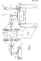
- Fig. 1 eine Draufsicht auf die Entnahmeseite einer Waffelbackmaschine mit Druckstation und Tüten-Waffelblatt-Wickeleinrichtung;
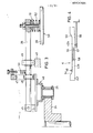
- Fig. 2 eine Schnittansicht etwa entsprechend der Schnittlinie II-II in Fig. 1,
- Fig. 3 eine bezüglich Fig. 2 alternative Ausführungsform, jedoch nur teilweise und vergrößert dargestellt und
- Fig. 4 die schematische Darstellung einer Steuerkulisse.
- Figure 1 is a plan view of the removal side of a waffle baking machine with a printing station and bag waffle sheet winding device.
- 2 is a sectional view approximately corresponding to the section line II-II in Fig. 1,
- Fig. 3 shows an alternative embodiment with respect to Fig. 2, but only partially and enlarged and
- Fig. 4 is a schematic representation of a control link.
In Fig. 1 ist eine schematisch gezeigte Waffelbackmaschine insgesamt mit 10 bezeichnet. Die Waffelbackmaschine 10 weist eine Backkette 11 auf, von welcher nur das Obertrum 0 zu sehen ist. Die umlaufend geführte Backkette 11 besitzt Backzangen bzw. Backformen 12, welche jeweils eine Oberform 13 und eine Unterform 14 aufweisen. Auf den Gravurflächen der Unterformen 14 liegen Waffelblätter 15 auf, welche über eine Entnahmevorrichtung 16 aufgenommen und mittels einer Tüten-Waffelblatt-Wickeleinrichtung 17 zu konischen Waffeltüten gewickelt bzw. gerollt werden sollen. Derartige mit 18 bezeichnete Waffeltüten werden mit Speiseeis befüllt.In Fig. 1, a schematically shown wafer baking machine is designated by 10 in total. The
Ober- und Unterform 13, 14 sind über Scharniere 19 miteinander verbunden, so daß die Oberform 13 von der Unterform 14 abgeklappt werden kann, wenn die Backform 12 mit flüssigem Teig gefüllt oder - wie in Fig. 1 dargestellt - aus der offenen Backform 12 das fertige Waffelblatt 15 entnommen werden soll.Upper and
Um ein Auf- und Zuklappen der Backformen 12 zu bewerkstelligen, ist jede Oberform 13 mit einem Kulissenstein 20 versehen, welcher in einer Kulisse 21 gleitet, deren räumlicher Verlauf die rechts in Fig. 1 dargestellte geschlossene Backform 12 öffnen kann, wie in Fig. 1 anhand der übrigen Backformen 12 dargestellt ist.In order to bring the
Aus Fig. 1 ist weiterhin eine Druckstation 22 zu ersehen. Die Druckstation 22 ist benachbart dem mit E bezeichneten Entnahmebereich der Waffelmaschine 10 angeordnet.A
Die Druckstation 22 besitzt ein Antriebsteil 23, welches eine in Fig. 1 nur gestrichelt dargestellte, über Kettenräder 24 angetriebene und umlaufend geführte Antriebskette 25 aufweist, an welcher Haltearme 26 höhenbeweglich, z.B. parallelhöhenbeweglich (Fig. 2) oder schwenkbar höhenbeweglich (Fig. 3) angelenkt sind.The
Die Bewegungsbahn der Antriebskette 25 läuft in einer horizontalen, den ebenen bzw. planen Waffelblättern 15 paralellen Ebene.The trajectory of the
Die Antriebskette 25 bildet ein Oval mit einer Längsseite L1 und mit' einer anderen Längsseite L2. Die eine Längsseite L1 bildet eine erste Bewegungsbahn benachbart den formseitig aufgenommenen offenliegenden Waffelblättern 15, während die Längsseite L2 eine zweite Bewegungsbahn bildet. Diese zweite Bewegungsbahn L2 ist benachbart einem Farbauftragsmittel, und zwar einem Stempelkissen 27, angeordnet. Steuermittel, und zwar eine Steuerkulisse K mit Kulissenbereichen K1 und K21 sorgen dafür, daß plattenartige Druckstempel 28 mit ihren dem Betrachter gemäß Fig. 1 abgewandten Unterseiten (Stempel-Gravurflächen 59) auf die noch heißen Waffelblätter 15 aufgesetzt werden, sodann von den Waffelblättern 15 abgehoben, schließlich auf die Stempelkissenfläche 29 aufgesetzt und wiederum von der Stempelkissenfläche 29 abgehoben werden. Die Förderrichtung der Backkette 11 ist mit x und die Umlaufrichtung der Haltearme 26 und Druckstempel 28 tragenden und umlaufend führenden Antriebskette 25 ist mit y bezeichnet.The
Die Funktion der Druckstation 22 verläuft wie folgt:The function of the
Bei der Position a kontaktiert der Druckstempel 28 die Stempelkissenfläche 29. Der bereits mit einem Farbauftrag versehene Druckstempel 28 in der Position b ist nach Verlassen des Kulissenbereichs K2 durch die insgesamt mit K bezeichnete Kulisse in eine angehobene Position übergeführt worden. Der ebenfalls mit einem Farbauftrag versehene Druckstempel 28 setzt in der Position c soeben auf das heiße Waffelblatt 15 auf, während sich der Druckstempel 28 in seiner Position d in vollem Druckkontakt mit dem Waffelblatt 15 befindet. Der Druckstempel in der Position e hebt hingegen soeben von dem Waffelblatt 15 ab, während der Druckstempel 28 in der Position f gegenüber der Position e ebenso wie gemäß der Position g angehoben ist. Von der Position h bis zur Position a verläuft der Absenkvorgang des Druckstempels 28 bis zum festen Kontakt mit der Stempelkissenfläche 29.At position a, the
Die mit einem beispielsweise figurativen Druckauftrag versehenen heißen Waffelblätter 15 gelangen mit der Backkette 11 schließlich an die Entnahmestation 16, und zwar an ein rampenförmig ansteigendes ebenes Transportblech 30 teilkreisartiger Grundform. An der Anlaufseite ist das Rampenblech 30 bei 36 schaberartig ausgebildet, so daß es einen Schabekontakt mit der Gravurfläche der Unterform 14 erlaubt. Hierdurch können die Waffelblätter 15 auf das Rampenblech 30 auflaufen, wo sie von Mitnehmerstempeln 31 drückend kontaktiert werden. Die Mitnehmerstempel 31 setzen hierbei jeweils auf einem farbfreien Bereich der bedruckten Waffel 15 auf, der durch die bogenförmig begrenzte Ausnehmung 60 des Druckstempels 28 gebildet ist.The
Die Mitnehmerstempel 31 sind endseitig von radial angeordneten Spinnenarmen 32 einer insgesamt mit 33 bezeichneten Förderspinne angeordnet, deren Drehachse 34 zentral zum Rampenblech 30 teilkreisförmiger Grundform angeordnet ist. Die Drehrichtung der Förderspinne 33 ist mit z angegeben. Auf diese Weise ist vorstellbar, daß die sich kreisförmig bewegenden Mitnehmerstempel 31 die Waffelblätter 15 auf dem Rampenblech 30 bis zum Wickeldorn 35 der Wickeleinrichtung 17 führen, wo die Verarbeitung zu konischen Waffeltüten 18 erfolgt.The
In Fig. 1 ist eine alternative Ausführungsform in Strichlinien angedeutet, gemäß welcher jeder Mitnehmerstempel 31 zugleich einen Druckstempel 28 bildet. Dieser Anordnung zugeordnet ist ein Stempelkissen 27 und eine ebenfalls mit K bezeichnete Kulisse, welche die höhenschwenkbeweglich angelenkten Spinnenarme 32 steuert. Bei dieser alternativen Ausführungsform würde das Bedrucken der Waffelblätter 15 unmittelbar hinter dem schaberförmigen Bereich 36 auf dem Rampenblech 30 erfolgen. Bei dieser alternativen Ausführungsform muß insbesondere durch Wahl der Konsistenz der verwendeten Lebensmittelfarbe dafür gesorgt werden, daß der Druckauftrag des Waffelblatts 15 bis zum Erreichen der Wickeleinrichtung 17 wischfest angetrocknet ist.An alternative embodiment is indicated in broken lines in FIG. 1, according to which each
Um bei der konkret in Fig. 1 dargestellten Ausführungsform mit der Druckstation 22 ein wischfestes Antrocknen des Druckauftrages zu gewährleisten, ist die Backkette 11 um eine Zusatzlänge A, die zusätzliche Trockenzeit des Farbauftrags garantiert, erweitert.In order to ensure a wipe-proof drying of the print job with the
Um ein Antrocknen der Druckfarbe an den Stempel-Gravurflächen 59 der Stempel 28 zu vermeiden, ist jeder Stempel 28 mit durchströmbaren Kühlungshohlräumen versehen, die über KUhlwasserschläuche (Zu- und Ablauf) 37 beschickt werden. Die Kühlwasserschläuche 37 sind in Fig. 1 lediglich repräsentativ für einen einzigen Druckstempel 28 eingezeichnet. Die Versorgung der Kühlwasserschläuche 37 erfolgt über einen mit der Geschwindigkeit der Antriebskette 25 in derselben Drehrichtung umlaufenden drehschieberartig aufgebauten zentralen Verteiler 38.In order to prevent the printing ink from drying on the stamp engraving surfaces 59 of the
Auch der Tragkörper des Stempelkissens 27 weist KUhlungshohlräume auf, welche ebenfalls über Kühlwasserschläuche 37 beaufschlagt werden. Wie unterhalb des Stempelkissens 27 mit einem Doppelpfeil angedeutet, wird das Stempelkissen 27 hin- und hergehend (beispielsweise über eine Viereckbewegung) angetrieben, so daß es während der Beaufschlagung des jeweiligen Druckstempels 28 mit Farbe dessen Bewegung in Richtung y folgen kann.The support body of the
Fig. 2 zeigt, wei beispielsweise die Haltearme 26 durch die Kulissenführungen im Bereich K1 und K2 höhenverstellt werden können. Hierzu weist die Kulisse K eine obere Kulissenschiene 39 und eine untere Kulissenschiene 40 auf, welche zwischen sich den Kulissenspalt 41 bilden. Die über Dämpfungsfedern 42 abgefederte Parallelführung der Haltearme 26 auf Führungsstangen 43 ist insgesamt mit der Bezugsziffer 44 versehen.2 shows, for example, how the holding
Im Unterschied zu Fig. 2 ist gemäß Fig. 3, bei welcher das Stempelkissen 27 und die Waffelbackmaschine 10 weggelassen sind, der Haltearm 26 nach Art eines Kipphebels bei 45 schwenkbar gelagert. Aus Fig. 2 sind auch ein Antriebskettenrad 24 sowie die Antriebskette 25 zu ersehen, welche eine Haltekonsole 46 mit dem Schwenklager 45 und einer mit einem Langloch 47 versehenen Parallelführung für einen Führungsstein 48 des schwenkbaren Haltearms 26 trägt. Die Anordnung gemäß Fig. 2 benötigt lediglich eine untere Kulissenschiene 40, auf der eine Führungsrolle 49 läuft. Der Haltearm 26 wird über eine einstellbare Druckfeder 50 ständig federnd nach unten gedrückt. Zur Vermeidung einer einseitigen Anlage des Druckstempels 28 sowohl auf der Stempelkissenfläche 29 als auch auf den Waffelblättern 15 ist der Druckstempel 28 über ein Raumgelenk 51 unter Zwischenschaltung einer Druckfeder 52 am freien Ende des Haltearms 26 raumbeweglich gehalten.In contrast to FIG. 2, according to FIG. 3, in which the
Fig. 4 zeigt im Zusammenhang mit Fig. 3, wie eine Kulissenführung verändert werden kann. Die Kulisse K gemäß Fig. 4 weist zwischen einer abfallenden Kurve 53 und einer ansteigenden Kurve 54 eine Geradführung 55 auf. Im Bereich der Geradführung 55 ist die Kulissenschiene in zwei Bereiche, d.h. in eine Kulissenschiene 40a und in eine weitere Kulissenschiene 40b aufgeteilt. Das Teil 40a ist raumfest gehalten, während das Teil 40b relativ zu 40a über einen Spindelstelltrieb 56 verstellbar ist, was über eine Langlochanordnung 57 mit Zapfen 58 geschieht. Auf diese Weise kann die Länge der Geradführung 55, und damit die Kontaktzeit zwischen Druckstempel 28 und Waffelblatt 15 einerseits bzw. Stempelkissen 27 andererseits, variiert werden. Es ist auch eine Ausführungsform denkbar, bei welcher beide Teilkulissen 40a, 40b jeweils über einen Stelltrieb 56 verschieblich sind. Auf diese Weise könnten sodann beide Kurven 53 und 54 verschoben werden.FIG. 4 shows in connection with FIG. 3 how a link guide can be changed. The 4 has a
Claims (22)
Priority Applications (1)
| Application Number | Priority Date | Filing Date | Title |
|---|---|---|---|
| AT86108853T ATE57292T1 (en) | 1985-07-05 | 1986-06-28 | PROCESS FOR THE MANUFACTURE OF SPECIALLY WRAPPED WAFFLE BAGS. |
Applications Claiming Priority (4)
| Application Number | Priority Date | Filing Date | Title |
|---|---|---|---|
| DE3524116 | 1985-07-05 | ||
| DE3524116 | 1985-07-05 | ||
| DE3613292 | 1986-04-19 | ||
| DE19863613292 DE3613292A1 (en) | 1985-07-05 | 1986-04-19 | METHOD FOR PRODUCING PARTICULARLY WRAPPED WAX BAGS |
Publications (3)
| Publication Number | Publication Date |
|---|---|
| EP0211225A2 true EP0211225A2 (en) | 1987-02-25 |
| EP0211225A3 EP0211225A3 (en) | 1987-10-07 |
| EP0211225B1 EP0211225B1 (en) | 1990-10-10 |
Family
ID=25833760
Family Applications (1)
| Application Number | Title | Priority Date | Filing Date |
|---|---|---|---|
| EP86108853A Expired - Lifetime EP0211225B1 (en) | 1985-07-05 | 1986-06-28 | Method for producing (especially) wound waffle cones |
Country Status (3)
| Country | Link |
|---|---|
| US (2) | US4761293A (en) |
| EP (1) | EP0211225B1 (en) |
| DE (2) | DE3613292A1 (en) |
Cited By (1)
| Publication number | Priority date | Publication date | Assignee | Title |
|---|---|---|---|---|
| AT410390B (en) * | 1997-07-23 | 2003-04-25 | Haas Franz Waffelmasch | BAG MOLDING MACHINE |
Families Citing this family (26)
| Publication number | Priority date | Publication date | Assignee | Title |
|---|---|---|---|---|
| DE3727162A1 (en) * | 1987-08-14 | 1989-02-23 | Heinrich Herting | MACHINE FOR WRAPPING FLAT WAFFLES TO WAX BAGS OR THE LIKE |
| DE4111011C1 (en) * | 1991-04-05 | 1992-06-25 | Gebr. Wiebrecht Ohg, 3400 Goettingen, De | Wound ice cream cone with coloured pattern - mfd. from dough baked in lower half of mould, and printed with dyes transferred to upper half of mould |
| US5162119A (en) * | 1991-04-09 | 1992-11-10 | Nabisco, Inc. | Printing and forming apparatus for making printed baked goods |
| US6616958B1 (en) * | 1993-07-07 | 2003-09-09 | Jack Guttman, Inc. | Method of making and using an edible film for decorating foodstuffs |
| US6319530B1 (en) * | 1993-07-07 | 2001-11-20 | Jack Guttman, Inc. | Method of photocopying an image onto an edible web for decorating iced baked goods |
| US6294189B1 (en) | 1996-08-07 | 2001-09-25 | De Novo, Inc. | Method of forming decontaminant food product |
| US5795586A (en) * | 1996-08-07 | 1998-08-18 | De Novo, Inc. | Toxin decontaminant food product and method of forming same |
| GB2316852B (en) * | 1996-09-04 | 2000-04-26 | Unilever Plc | Process for the preparation of a food product |
| US5770075A (en) * | 1997-02-24 | 1998-06-23 | Geoffroy; David P. | Beverage filter |
| US20060087686A1 (en) * | 1998-03-25 | 2006-04-27 | John Anderson | Decorating system for edible products |
| US20020008751A1 (en) * | 1998-03-25 | 2002-01-24 | Stephen L. Spurgeon | Decorating system for edible items |
| US20020155197A1 (en) * | 2001-04-18 | 2002-10-24 | David Klug | Sugar wafer with confectionery filling and method for making same |
| US20050061184A1 (en) * | 2001-04-20 | 2005-03-24 | Russell John R. | Printing process with edible inks |
| EP1252821B1 (en) * | 2001-04-27 | 2005-07-20 | Kraft Foods R&D, Inc. | Method of and apparatus for producing endless rolls of a resilient foodstuff |
| US20040101598A1 (en) * | 2002-11-26 | 2004-05-27 | Pamela Paulhus | Dessert cone with embedded strip |
| US20100278979A1 (en) * | 2003-08-06 | 2010-11-04 | Signed Originals, Inc. | Interlocking edible sideliner for cake decoration, method, three-dimensional cake sculpture method and product |
| US20060251777A1 (en) * | 2003-08-06 | 2006-11-09 | Koplish Debra L | Interlocking edible sideliner for cake decoration, method, three-dimensional cake sculpture method and product |
| US7763296B2 (en) * | 2004-12-16 | 2010-07-27 | Stimson Judith N | Food items, systems and methods |
| DE102005029611B3 (en) * | 2005-06-23 | 2006-11-23 | Karl Oexmann, Inh. Wolfgang Oexmann | Apparatus for making waffles comprises a device for delivering food shavings that is located upstream of a dough delivery device |
| US20080118605A1 (en) * | 2006-11-22 | 2008-05-22 | Nanette Theresa Owen | Novel enhanced baking stamp |
| US20140170074A1 (en) * | 2010-09-21 | 2014-06-19 | Victoria Link Limited | Safety material and system |
| JP5779636B2 (en) * | 2013-12-19 | 2015-09-16 | 日世株式会社 | Confectionery manufacturing apparatus, confectionery manufacturing method and confectionery |
| US20150201625A1 (en) * | 2014-01-23 | 2015-07-23 | Conewich Enterprises Limited Partnership | Bake Form for Manufacturing a Food Product |
| CN104472609B (en) * | 2014-12-22 | 2016-10-05 | 广东省机械研究所 | A kind of modified model ice cream crackling cylinder rolling device |
| CN112911936A (en) * | 2018-10-19 | 2021-06-04 | 联合利华知识产权控股有限公司 | Apparatus and method for manufacturing cone sheet of baked wafer |
| IT201800011109A1 (en) * | 2018-12-14 | 2020-06-14 | Xlogic S R L | "Apparatus for decorating ice cream cones." |
Citations (5)
| Publication number | Priority date | Publication date | Assignee | Title |
|---|---|---|---|---|
| US2069026A (en) * | 1935-10-01 | 1937-01-26 | Joseph Shapiro | Baking plate |
| US4223204A (en) * | 1978-08-17 | 1980-09-16 | Benedict Melvin A | Machine for marking baked goods |
| DE3311035A1 (en) * | 1982-03-26 | 1983-09-29 | Franz Haas Waffelmaschinen Industriegesellschaft m.b.H., 1210 Wien | Waffle-baking oven with pressing roller |
| DE3304383A1 (en) * | 1983-02-09 | 1984-08-09 | Hellmuth Walter Gmbh, 2300 Kiel | Device for manufacturing rolled, conical sweet hollow waffles and the like |
| US4578273A (en) * | 1981-04-07 | 1986-03-25 | Keebler Company | Printing of foods |
Family Cites Families (9)
| Publication number | Priority date | Publication date | Assignee | Title |
|---|---|---|---|---|
| DE531141C (en) * | 1934-07-21 | Waffel Und Biskuit Fabrik Hens | Waffle tongs | |
| CH53767A (en) * | 1910-08-05 | 1912-04-01 | Christian Burky August | Device for baking cakes |
| US4111624A (en) * | 1976-10-28 | 1978-09-05 | Hanson Douglas R | Dough piece imprinter and controls therefore |
| US4313964A (en) * | 1977-11-25 | 1982-02-02 | Silver Cloud Enterprises, Inc. | Apparatus and method for producing edible food fillable cones |
| US4168662A (en) * | 1978-04-28 | 1979-09-25 | American Can Company | Videojet ink for printing on food products |
| US4285978A (en) * | 1979-03-21 | 1981-08-25 | Quinlivan Sharon L | Method for decorating baked goods and the like |
| US4349574A (en) * | 1981-09-28 | 1982-09-14 | Deer Park Baking Co. | Method and apparatus to make cookies |
| US4619832A (en) * | 1984-04-16 | 1986-10-28 | Gold Bond Ice Cream, Inc. | Forming and conveying of baked confection shells |
| AT384933B (en) * | 1984-05-04 | 1988-01-25 | Haas Franz Waffelmasch | METHOD AND DEVICE FOR THE PRODUCTION OF ROLLED, PREFERABLY CONE-SHAPED CAVES |
-
1986
- 1986-04-19 DE DE19863613292 patent/DE3613292A1/en active Granted
- 1986-06-28 EP EP86108853A patent/EP0211225B1/en not_active Expired - Lifetime
- 1986-06-28 DE DE8686108853T patent/DE3674853D1/en not_active Expired - Fee Related
- 1986-07-07 US US06/882,267 patent/US4761293A/en not_active Expired - Fee Related
-
1988
- 1988-03-18 US US07/169,681 patent/US4859476A/en not_active Expired - Fee Related
Patent Citations (5)
| Publication number | Priority date | Publication date | Assignee | Title |
|---|---|---|---|---|
| US2069026A (en) * | 1935-10-01 | 1937-01-26 | Joseph Shapiro | Baking plate |
| US4223204A (en) * | 1978-08-17 | 1980-09-16 | Benedict Melvin A | Machine for marking baked goods |
| US4578273A (en) * | 1981-04-07 | 1986-03-25 | Keebler Company | Printing of foods |
| DE3311035A1 (en) * | 1982-03-26 | 1983-09-29 | Franz Haas Waffelmaschinen Industriegesellschaft m.b.H., 1210 Wien | Waffle-baking oven with pressing roller |
| DE3304383A1 (en) * | 1983-02-09 | 1984-08-09 | Hellmuth Walter Gmbh, 2300 Kiel | Device for manufacturing rolled, conical sweet hollow waffles and the like |
Cited By (1)
| Publication number | Priority date | Publication date | Assignee | Title |
|---|---|---|---|---|
| AT410390B (en) * | 1997-07-23 | 2003-04-25 | Haas Franz Waffelmasch | BAG MOLDING MACHINE |
Also Published As
| Publication number | Publication date |
|---|---|
| DE3674853D1 (en) | 1990-11-15 |
| EP0211225A3 (en) | 1987-10-07 |
| US4761293A (en) | 1988-08-02 |
| EP0211225B1 (en) | 1990-10-10 |
| US4859476A (en) | 1989-08-22 |
| DE3613292A1 (en) | 1987-01-15 |
| DE3613292C2 (en) | 1987-08-27 |
Similar Documents
| Publication | Publication Date | Title |
|---|---|---|
| EP0211225B1 (en) | Method for producing (especially) wound waffle cones | |
| EP3169521B1 (en) | Device for printing hollow articles | |
| EP3169520B1 (en) | Device with several printing units each for printing on hollow bodies | |
| EP3169519B1 (en) | Printing unit with plate cylinder and plate changing device | |
| DE2256815B2 (en) | Screen printing device for sheet material | |
| DE102016201140A1 (en) | Method for operating a device having a segment wheel for printing hollow bodies | |
| DE102016201137B4 (en) | Device for printing hollow bodies | |
| DE2338053A1 (en) | MACHINE FOR PRINTING CERAMIC PRODUCTS | |
| EP3169522B1 (en) | Inking unit of a printing unit | |
| EP0003983A1 (en) | Screen printing process and apparatus therefor | |
| EP1497124B1 (en) | Pad printer | |
| DE60117921T2 (en) | DEVICE AND METHOD FOR THE PRODUCTION OF CEREAL CAKE | |
| DE102014213813B4 (en) | Device for printing in each case a lateral surface of hollow bodies | |
| DE102014213805B3 (en) | Inking unit of a printing unit | |
| WO2016008701A1 (en) | Inking unit of a printing unit | |
| DE102016201139B4 (en) | Device for printing hollow bodies | |
| DE102014213807B4 (en) | Apparatus for printing on each of a lateral surface having hollow bodies | |
| DE102014213812B3 (en) | Device for arranging a printing form cylinder and an inking unit of a printing unit | |
| DE2154671A1 (en) | Device for decorating workpieces | |
| DE677034C (en) | Device for single-color or multi-color printing of individual blanks, in particular beer glass saucers | |
| DE19534827C2 (en) | Device for printing flat individual objects | |
| DE102014213811A1 (en) | Printing unit with a printing forme cylinder | |
| DE194361C (en) | ||
| DE1107248B (en) | Squeegee for a screen or stencil printing machine | |
| DE2121725B2 (en) | Printing or varnishing unit for tube - is adjustable to tube or hollow object circumference to control print placement |
Legal Events
| Date | Code | Title | Description |
|---|---|---|---|
| PUAI | Public reference made under article 153(3) epc to a published international application that has entered the european phase |
Free format text: ORIGINAL CODE: 0009012 |
|
| AK | Designated contracting states |
Kind code of ref document: A2 Designated state(s): AT BE CH DE FR GB IT LI LU NL SE |
|
| PUAL | Search report despatched |
Free format text: ORIGINAL CODE: 0009013 |
|
| AK | Designated contracting states |
Kind code of ref document: A3 Designated state(s): AT BE CH DE FR GB IT LI LU NL SE |
|
| 17P | Request for examination filed |
Effective date: 19871013 |
|
| 17Q | First examination report despatched |
Effective date: 19890705 |
|
| ITF | It: translation for a ep patent filed |
Owner name: CALVANI SALVI E VERONELLI S.R.L. |
|
| GRAA | (expected) grant |
Free format text: ORIGINAL CODE: 0009210 |
|
| AK | Designated contracting states |
Kind code of ref document: B1 Designated state(s): AT BE CH DE FR GB IT LI LU NL SE |
|
| REF | Corresponds to: |
Ref document number: 57292 Country of ref document: AT Date of ref document: 19901015 Kind code of ref document: T |
|
| GBT | Gb: translation of ep patent filed (gb section 77(6)(a)/1977) | ||
| REF | Corresponds to: |
Ref document number: 3674853 Country of ref document: DE Date of ref document: 19901115 |
|
| ET | Fr: translation filed | ||
| ITTA | It: last paid annual fee | ||
| PLBE | No opposition filed within time limit |
Free format text: ORIGINAL CODE: 0009261 |
|
| STAA | Information on the status of an ep patent application or granted ep patent |
Free format text: STATUS: NO OPPOSITION FILED WITHIN TIME LIMIT |
|
| 26N | No opposition filed | ||
| PGFP | Annual fee paid to national office [announced via postgrant information from national office to epo] |
Ref country code: GB Payment date: 19940623 Year of fee payment: 9 Ref country code: DE Payment date: 19940623 Year of fee payment: 9 |
|
| PGFP | Annual fee paid to national office [announced via postgrant information from national office to epo] |
Ref country code: FR Payment date: 19940628 Year of fee payment: 9 Ref country code: AT Payment date: 19940628 Year of fee payment: 9 |
|
| PGFP | Annual fee paid to national office [announced via postgrant information from national office to epo] |
Ref country code: BE Payment date: 19940629 Year of fee payment: 9 |
|
| PGFP | Annual fee paid to national office [announced via postgrant information from national office to epo] |
Ref country code: SE Payment date: 19940630 Year of fee payment: 9 Ref country code: NL Payment date: 19940630 Year of fee payment: 9 Ref country code: LU Payment date: 19940630 Year of fee payment: 9 |
|
| EPTA | Lu: last paid annual fee | ||
| EAL | Se: european patent in force in sweden |
Ref document number: 86108853.2 |
|
| PG25 | Lapsed in a contracting state [announced via postgrant information from national office to epo] |
Ref country code: LU Free format text: LAPSE BECAUSE OF NON-PAYMENT OF DUE FEES Effective date: 19950628 Ref country code: GB Effective date: 19950628 Ref country code: AT Effective date: 19950628 |
|
| PG25 | Lapsed in a contracting state [announced via postgrant information from national office to epo] |
Ref country code: SE Effective date: 19950629 |
|
| PG25 | Lapsed in a contracting state [announced via postgrant information from national office to epo] |
Ref country code: BE Effective date: 19950630 |
|
| PGFP | Annual fee paid to national office [announced via postgrant information from national office to epo] |
Ref country code: CH Payment date: 19950710 Year of fee payment: 10 |
|
| BERE | Be: lapsed |
Owner name: FIRMA KARL OEXMANN INH. WOLFGANG OEXMANN Effective date: 19950630 |
|
| PG25 | Lapsed in a contracting state [announced via postgrant information from national office to epo] |
Ref country code: NL Effective date: 19960101 |
|
| GBPC | Gb: european patent ceased through non-payment of renewal fee |
Effective date: 19950628 |
|
| PG25 | Lapsed in a contracting state [announced via postgrant information from national office to epo] |
Ref country code: FR Effective date: 19960229 |
|
| NLV4 | Nl: lapsed or anulled due to non-payment of the annual fee |
Effective date: 19960101 |
|
| PG25 | Lapsed in a contracting state [announced via postgrant information from national office to epo] |
Ref country code: DE Effective date: 19960301 |
|
| EUG | Se: european patent has lapsed |
Ref document number: 86108853.2 |
|
| REG | Reference to a national code |
Ref country code: FR Ref legal event code: ST |
|
| PG25 | Lapsed in a contracting state [announced via postgrant information from national office to epo] |
Ref country code: LI Effective date: 19960630 Ref country code: CH Effective date: 19960630 |
|
| REG | Reference to a national code |
Ref country code: CH Ref legal event code: PL |
|
| PG25 | Lapsed in a contracting state [announced via postgrant information from national office to epo] |
Ref country code: IT Free format text: LAPSE BECAUSE OF NON-PAYMENT OF DUE FEES;WARNING: LAPSES OF ITALIAN PATENTS WITH EFFECTIVE DATE BEFORE 2007 MAY HAVE OCCURRED AT ANY TIME BEFORE 2007. THE CORRECT EFFECTIVE DATE MAY BE DIFFERENT FROM THE ONE RECORDED. Effective date: 20050628 |