EP0212737A2 - Ultrasonic imaging apparatus - Google Patents
Ultrasonic imaging apparatus Download PDFInfo
- Publication number
- EP0212737A2 EP0212737A2 EP86201366A EP86201366A EP0212737A2 EP 0212737 A2 EP0212737 A2 EP 0212737A2 EP 86201366 A EP86201366 A EP 86201366A EP 86201366 A EP86201366 A EP 86201366A EP 0212737 A2 EP0212737 A2 EP 0212737A2
- Authority
- EP
- European Patent Office
- Prior art keywords
- electrode
- electrodes
- transducer
- lens
- focusing
- Prior art date
- Legal status (The legal status is an assumption and is not a legal conclusion. Google has not performed a legal analysis and makes no representation as to the accuracy of the status listed.)
- Granted
Links
- 238000003384 imaging method Methods 0.000 title claims abstract description 8
- 229910010293 ceramic material Inorganic materials 0.000 claims description 2
- 238000005520 cutting process Methods 0.000 claims description 2
- 230000001934 delay Effects 0.000 abstract description 5
- 238000003491 array Methods 0.000 description 6
- 238000010586 diagram Methods 0.000 description 2
- 238000002592 echocardiography Methods 0.000 description 2
- 230000000694 effects Effects 0.000 description 2
- 239000000463 material Substances 0.000 description 2
- 238000002604 ultrasonography Methods 0.000 description 2
- 230000006978 adaptation Effects 0.000 description 1
- 238000004458 analytical method Methods 0.000 description 1
- 230000005540 biological transmission Effects 0.000 description 1
- 239000002178 crystalline material Substances 0.000 description 1
- 238000009826 distribution Methods 0.000 description 1
- 239000002305 electric material Substances 0.000 description 1
- 230000005284 excitation Effects 0.000 description 1
- 238000004519 manufacturing process Methods 0.000 description 1
- 238000000034 method Methods 0.000 description 1
Images


Classifications
-
- B—PERFORMING OPERATIONS; TRANSPORTING
- B06—GENERATING OR TRANSMITTING MECHANICAL VIBRATIONS IN GENERAL
- B06B—METHODS OR APPARATUS FOR GENERATING OR TRANSMITTING MECHANICAL VIBRATIONS OF INFRASONIC, SONIC, OR ULTRASONIC FREQUENCY, e.g. FOR PERFORMING MECHANICAL WORK IN GENERAL
- B06B1/00—Methods or apparatus for generating mechanical vibrations of infrasonic, sonic, or ultrasonic frequency
- B06B1/02—Methods or apparatus for generating mechanical vibrations of infrasonic, sonic, or ultrasonic frequency making use of electrical energy
- B06B1/06—Methods or apparatus for generating mechanical vibrations of infrasonic, sonic, or ultrasonic frequency making use of electrical energy operating with piezoelectric effect or with electrostriction
- B06B1/0607—Methods or apparatus for generating mechanical vibrations of infrasonic, sonic, or ultrasonic frequency making use of electrical energy operating with piezoelectric effect or with electrostriction using multiple elements
- B06B1/0622—Methods or apparatus for generating mechanical vibrations of infrasonic, sonic, or ultrasonic frequency making use of electrical energy operating with piezoelectric effect or with electrostriction using multiple elements on one surface
- B06B1/0629—Square array
-
- G—PHYSICS
- G01—MEASURING; TESTING
- G01S—RADIO DIRECTION-FINDING; RADIO NAVIGATION; DETERMINING DISTANCE OR VELOCITY BY USE OF RADIO WAVES; LOCATING OR PRESENCE-DETECTING BY USE OF THE REFLECTION OR RERADIATION OF RADIO WAVES; ANALOGOUS ARRANGEMENTS USING OTHER WAVES
- G01S7/00—Details of systems according to groups G01S13/00, G01S15/00, G01S17/00
- G01S7/52—Details of systems according to groups G01S13/00, G01S15/00, G01S17/00 of systems according to group G01S15/00
- G01S7/52017—Details of systems according to groups G01S13/00, G01S15/00, G01S17/00 of systems according to group G01S15/00 particularly adapted to short-range imaging
- G01S7/52046—Techniques for image enhancement involving transmitter or receiver
Landscapes
- Engineering & Computer Science (AREA)
- Mechanical Engineering (AREA)
- Computer Networks & Wireless Communication (AREA)
- Physics & Mathematics (AREA)
- General Physics & Mathematics (AREA)
- Radar, Positioning & Navigation (AREA)
- Remote Sensing (AREA)
- Investigating Or Analyzing Materials By The Use Of Ultrasonic Waves (AREA)
- Ultra Sonic Daignosis Equipment (AREA)
Abstract
Description
- The invention relates to an ultrasonic imaging apparatus comprising a transducer system comprising
a plate of piezoelectric ceramic material having two major surfaces,
a first conductive electrode serving as a ground electrode disposed on the first of said major opposed surfaces, and
a second conductive electrode serving as an active electrode disposed on the second of said major surfaces. The transducer system may be either a linear array or a phased array. - The general characteristics of diagnostic ultrasound transducers are fairly well known in the prior art. Since the depth of field of present mechanical lenses is very limited, lenses have been proposed to image either close to or far from the scanned object, using two types of transducers for different applications. Alternatively, purely electronic solutions have been proposed. U.S. Patent 4,371,805 discloses an ultrasonic transducer arrangement, the frequency of which is freely selectable within a certain range for the purpose of providing improved imaging conditions, particularly increased resolution in the production of images of a scanned space, This patent teaches an embodiment in which electronic focusing in the longitudinal direction as well in the transverse direction of the transducer should also be possible. The major drawback of the transducer of this patent is the complex electronics required to make the design functional. British Patent No. 1,514,050 is directed to an annular transducer arrangement with a fixed geometry rather than stepped electrodes. It uses a disc rather than a cylindrical lens and cannot be used in phased arrays. U.S. Patent No. 4,242,912 discloses a method for focusing an ultrasonic beam using time shifted pulsing of adjacent transducer elements.
- In an ultrasonic imaging system, the performance of the transducer is significantly determined by the shape of the acoustic beam in both the direction of the scan (hereinafter the longitudinal direction) and normal to the scan (i.e., the elevation, hereinafter the transverse direction). A mechanical lens secures focusing of linear arrays and phased arrays in the direction perpendicular to the field of view However, the mechanical lens is a fixed focus type of lens and hence provides a very limited depth of field. It is an object of the present invention to improve the depth of field of the elevation focusing without very complex electronics being required.
- To achieve this object the apparatus according to the invention is characterized in that the transducer system further comprises
a convex cylindrical lens positioned over said first electrode surface,
in that said active electrode is subdivided into a plurality of active transducer electrodes, said electrode being divided transversely into a plurality of columns by cutting through said electrode and said electrode being divided longitudinally by at least two cuts such that said each column has at least three transducer electrodes, one central electrode and two side electrodes, the width of the three electrodes being such that the time of flight difference between the inner and outer border of the side electrodes is comparable to the time of flight difference over the central electrode, for all focusing depths concerned,
and in that the apparatus further comprises :
switching and circuit means to pulse the transducer elements under said transducer electrodes and to receive the pulse echoes returned to said transducers,
first delay means to focus said transducer system longitudinally by controlling the pulsing and receiving of said central and side electrodes and
second delay means to focus said transducer system transversely by controlling said side electrodes with respect to said central electrodes. When piezoelectric material with low cross talk is used, scoring of the electrodes is sufficient. When the piezoelectric material has substantial cross-talk, the piezoelectric material should be diced. Electronic delays are applied to the signals, transmitted from the middle longitudinal areas toward the scanned object and received from the scanned object by the electrodes, in order to correct for phase errors which would normally occur when the mechanical lens is out of focus. Only a few electrodes are needed when there is a mechanical prefocusing. Electronic focusing in the longitudinal direction is obtained by dividing the electrodes transversely. Switches are connected to each rectangular electrode. The signals are fed to and come from appropriate sets of delay circuits. This combination of electronic focusing in a mechanically prefocused transducer requires fewer elements and consequently fewer electronic components, while providing focusing properties and a depth of field in the transverse direction superior to that previously obtained, and may be used with both linear and phased arrays. - The invention is illustrated, by way of example, in the accompanying drawings, in which
- Figure 1 is a perspective view of the electronically adjustable mechanical lens of the present invention.
- Figure 2 is a plan view of the back face electrode of the electronically adjustable mechanical lens of Figure 1.
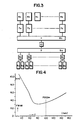
- Figure 3 is a block diagram of the electronic configuration for an electronically adjustable mechanical lens having an aperture of 16 elements longitudinally, and 3 elements transversely.
- Figure 4 is a graph of the resolution of the reference mechanical lens.
- Figure 5 is a graph showing the one way directivity function at Z = 150.0 mm.
- Figure 6 is a graph showing the one way directivity function at Z = 30.0 mm.
- Figure 7 is a graph showing the one way directivity functions at Z = 80.0 mm.
- Figure 8 is a graph showing the comparison of resolution at Z = 30.0, 80.0 and 150.0 mm.
- Referring now specifically to Figure 1, this figure illustrates an exaggerated perspective profile view of the electronically adjustable mechanical lens for ultrasonic linear array and phased array imaging of the present invention. This lens includes a piezoelectric
crystalline material 12 in a plate or strip form, anactive electrode 14 on one side and aground electrode 16 on the other side. Amechanical lens 18 is placed over theground electrode 16 such that the mechanical lens and the ground electrode are on the patient side of the transducer. Electronic focusing in the longitudinal direction is conventional, theactive electrode 14 being divided transversely into segments (a, b, c, ...) as illustrated in Figure 2. - According to the invention, the back face
active electrode 14 is also divided longitudinally into strips, preferably threestrips figure elements elements central electrodes - The electronics (switches, multiplexers, etc.) may be in the scan head, resulting in reduced lead count in the cable; or the electronics may reside in the main frame, necessitating as many leads as acoustical elements in the cable.
- Figure 3 is a block diagram of the basic electronic circuit configuration for the adjustable mechanical lens of the present invention having a 16 element aperture longitudinally.
Elements element 10 represents a delay to adjust the timing in the transverse direction, which can be either a positive or a negative delay. Whenelement 10 is dynamically varied, during reception of the echoes, the so-called tracking focusing can be obtained. Delays 8a, 8b ... 8k are each connected to twoelements 5a/6a, 5b/6b, etc. because the phase requirements of these grouped elements are the same. For Fig. 3 we have discussed so far focusing during reception. The same structure can also be used for transmission. This allows focusing transversely at any depth. - With reference to Figures 4 through 8, the electronically adjustable mechanical lens of the present invention is best understood by a discussion of the characteristics of a reference mechanical lens such as commonly used in the prior art transducers, and the effect of electronically focusing such a lens according to the present invention. All data wil be given in millimeters, unless indicated otherwise.
- The characteristics of the reference lens are as follows:
mechanical radius of curvature: 50.0 mm, having an ultrasound propagation velocity of 1.0 mm per /us; hence, an ultrasonic radius of curvature equal to 100.0 mm;
width: 15.0 mm;
resonant frequency : 3.0 mHz, medium backing and one quarter wave adaptation layer, so a typical short impulse response results; and
having double resonant-pulse excitation, that is, two short pulses half a wave long and one wave length apart. The aperture of the transducer consists of 16 elements with a pitch of 0.95 mm. The electronic focal length for focusing in the longitudinal direction is 80.0 mm. - Figure 4 shows the FWHM (Full Width at half Maximum) of the main lobe of the directivity function of the mechanical lens, i.e. perpendicular to the image plane as a function of depth Z. The curve is characteristic in that :
the best resolution is found at 80.0 mm; and that defocusing leads to poorer resolution at leaser and greater depths. - The purpose of the design of the lens of the present invention is to improve the resolution, both at closer range and further out. As an example we will analyse directivity at depth Z = 30.0 mm and Z = 150.0 mm. FOCZm designates the natural ultrasonic radius of curvature of the mechanical lens. The value FOCZm = 100.0 is indicated in Figure 4. FOCZ₁ will mean the electronically adjusted focal length of the mechanical lens.
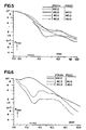
- One way directivity functions at Z = 30.0 mm are given in Figure 6 (normalized maximum pressure Pmax as a function of transversal direction Y to beam axis).
- The curve (Fig. 6) for no external focusing, FOCZm = 100.0, shows the strong effect of defocusing at this distance. With FOCZm = 80.0 or 60.0 mm, the FOCZ₁ = 30.0 mm, much better results are obtained. With FOCZm = 100.0 and FOCZ₁ = 30.0, less gain would result. Apparently, in order to get good results at Z = 30.0 mm, FOCZm should be brought in closer than the original choice of FOCZm = 100.0.
- One-way directivity functions at Z = 150.0 mm are given in Figure 5 (normalized maximum pressure Pmax as a function of transversal direction Y to beam axis). There is some gain in going to external focusing, with FOCZm = 100.0. As has been shown above, the resolution can be improved considerably at Z = 30.0 mm, provided that FOCZm is chosen smaller. Figure 5 now shows that comparable resolutions are obtained at Z = 150.0 mm, when FOCZm is reduced to 80.0 mm, or even to 60.0 mm.
-
- Equivalent resolutions (Fig. 7) are obtained for the following situations : FOCZm = 100.0 mm / no extern nal focusing, FOCZm = 80.0 mm/no external focusing, and FOCZm = 60.0mm/FOCZ₁ = 80.0mm. This is to be expected; the phase errors are small. So the choice of FOCZm is not critical in the middle region of the image.
- Typical FWHM values are compared in Figure 8. It can be seen that substantial gain in resolution is obtained at the smaller depths, with the active electrode divided up into three strips longitudinally, and the lens is focused electronically in the transverse plane according to the present invention.
Claims (1)
a plate of piezoelectric ceramic material having two major surfaces,
a first conductive electrode serving as a ground electrode dispos3d on the first of said major opposed surfaces, and
a second conductive electrode serving as an active electrode disposed on the second of said major surfaces,
characterized in that the transducer system further comprises
a convex cylindrical lens positioned over said first electrode surface,
in that said active electrode is subdivided into a plurality of active transducer electrodes, said electrode being divided transversely into a plurality of columns by cutting through said electrode and said electrode being divided longitudinally by at least two cuts such that said each column has at least three transducer electrodes, one central electrode and two side elctrodes, the width of the three electrodes being such that the time of flight difference between the inner and outer border of the side electrodes is comparable to the time of flight difference over the central electrode, for all focusing depths concerned.
Applications Claiming Priority (2)
| Application Number | Priority Date | Filing Date | Title |
|---|---|---|---|
| US767403 | 1985-08-20 | ||
| US06/767,403 US4670683A (en) | 1985-08-20 | 1985-08-20 | Electronically adjustable mechanical lens for ultrasonic linear array and phased array imaging |
Publications (3)
| Publication Number | Publication Date |
|---|---|
| EP0212737A2 true EP0212737A2 (en) | 1987-03-04 |
| EP0212737A3 EP0212737A3 (en) | 1988-08-31 |
| EP0212737B1 EP0212737B1 (en) | 1994-03-23 |
Family
ID=25079371
Family Applications (1)
| Application Number | Title | Priority Date | Filing Date |
|---|---|---|---|
| EP86201366A Expired - Lifetime EP0212737B1 (en) | 1985-08-20 | 1986-08-04 | Ultrasonic imaging apparatus |
Country Status (7)
| Country | Link |
|---|---|
| US (1) | US4670683A (en) |
| EP (1) | EP0212737B1 (en) |
| JP (1) | JPH0744929B2 (en) |
| CA (1) | CA1282163C (en) |
| DE (1) | DE3689736T2 (en) |
| ES (1) | ES2001097A6 (en) |
| IL (1) | IL79757A0 (en) |
Cited By (3)
| Publication number | Priority date | Publication date | Assignee | Title |
|---|---|---|---|---|
| EP0370107A1 (en) * | 1987-06-30 | 1990-05-30 | Yokogawa Medical Systems, Ltd | Ultrasonic diagnostic apparatus |
| EP0426099A2 (en) * | 1989-10-30 | 1991-05-08 | Fujitsu Limited | Ultrasonic transducer |
| US5617865A (en) * | 1995-03-31 | 1997-04-08 | Siemens Medical Systems, Inc. | Multi-dimensional ultrasonic array interconnect |
Families Citing this family (20)
| Publication number | Priority date | Publication date | Assignee | Title |
|---|---|---|---|---|
| US4998549A (en) * | 1987-04-29 | 1991-03-12 | Verteq, Inc. | Megasonic cleaning apparatus |
| US4869278A (en) * | 1987-04-29 | 1989-09-26 | Bran Mario E | Megasonic cleaning apparatus |
| US5037481B1 (en) * | 1987-04-29 | 1993-05-11 | Verteq, Inc. | Megasonic cleaning method |
| FR2620294B1 (en) * | 1987-09-07 | 1990-01-19 | Technomed Int Sa | PIEZOELECTRIC DEVICE WITH REDUCED NEGATIVE WAVES, AND USE THEREOF FOR EXTRA-BODY LITHOTRITIS OR FOR THE DESTRUCTION OF SPECIAL TISSUES |
| JP2759808B2 (en) * | 1988-10-05 | 1998-05-28 | 株式会社日立メディコ | Ultrasound diagnostic equipment |
| US5301168A (en) * | 1993-01-19 | 1994-04-05 | Hewlett-Packard Company | Ultrasonic transducer system |
| US5349262A (en) * | 1994-02-22 | 1994-09-20 | Hewlett-Packard Company | Phased array ultrasound imaging system with dynamic elevation focusing |
| US5462057A (en) * | 1994-06-06 | 1995-10-31 | Hewlett-Packard Company | Ultrasound imaging system using line splicing and parallel receive beam formation |
| US5677491A (en) * | 1994-08-08 | 1997-10-14 | Diasonics Ultrasound, Inc. | Sparse two-dimensional transducer array |
| US5979239A (en) * | 1997-04-28 | 1999-11-09 | The United States Of America As Represented By The Administrator Of The National Aeronautics And Space Administration | Ultrasonic imaging system |
| DE10018355A1 (en) * | 2000-04-13 | 2001-12-20 | Siemens Ag | Ultrasound transducer; has piezoelectric body with several transducer elements and strip conductor foil on flat side with conductive track pattern to determine arrangement of transducer elements |
| US6622562B2 (en) * | 2001-01-05 | 2003-09-23 | Bjorn A. J. Angelsen | Multi pre-focused annular array for high resolution ultrasound imaging |
| US7635332B2 (en) * | 2003-02-14 | 2009-12-22 | Siemens Medical Solutions Usa, Inc. | System and method of operating microfabricated ultrasonic transducers for harmonic imaging |
| US7087023B2 (en) * | 2003-02-14 | 2006-08-08 | Sensant Corporation | Microfabricated ultrasonic transducers with bias polarity beam profile control and method of operating the same |
| US7780597B2 (en) * | 2003-02-14 | 2010-08-24 | Siemens Medical Solutions Usa, Inc. | Method and apparatus for improving the performance of capacitive acoustic transducers using bias polarity control and multiple firings |
| US7618373B2 (en) | 2003-02-14 | 2009-11-17 | Siemens Medical Solutions Usa, Inc. | Microfabricated ultrasonic transducer array for 3-D imaging and method of operating the same |
| US10324033B2 (en) | 2012-07-20 | 2019-06-18 | Samsung Electronics Co., Ltd. | Image processing apparatus and method for correcting an error in depth |
| US11167154B2 (en) * | 2012-08-22 | 2021-11-09 | Medtronic, Inc. | Ultrasound diagnostic and therapy management system and associated method |
| US9494454B2 (en) * | 2013-12-06 | 2016-11-15 | Joseph Baumoel | Phase controlled variable angle ultrasonic flow meter |
| US9752907B2 (en) | 2015-04-14 | 2017-09-05 | Joseph Baumoel | Phase controlled variable angle ultrasonic flow meter |
Citations (4)
| Publication number | Priority date | Publication date | Assignee | Title |
|---|---|---|---|---|
| DE2718772A1 (en) * | 1976-04-27 | 1977-11-03 | Tokyo Shibaura Electric Co | PROBE FOR AN ULTRASONIC DIAGNOSTIC DEVICE |
| FR2367289A1 (en) * | 1976-10-11 | 1978-05-05 | Anvar | IMPROVEMENTS IN ACOUSTIC IMAGE TRAINING METHODS AND DEVICES |
| DE3119295A1 (en) * | 1981-05-14 | 1982-12-16 | Siemens AG, 1000 Berlin und 8000 München | DEVICE FOR DESTROYING CONCRETE IN BODIES |
| US4537074A (en) * | 1983-09-12 | 1985-08-27 | Technicare Corporation | Annular array ultrasonic transducers |
Family Cites Families (9)
| Publication number | Priority date | Publication date | Assignee | Title |
|---|---|---|---|---|
| CH608103A5 (en) * | 1975-12-01 | 1978-12-15 | Hoffmann La Roche | |
| US4155259A (en) * | 1978-05-24 | 1979-05-22 | General Electric Company | Ultrasonic imaging system |
| US4211949A (en) * | 1978-11-08 | 1980-07-08 | General Electric Company | Wear plate for piezoelectric ultrasonic transducer arrays |
| US4385255A (en) * | 1979-11-02 | 1983-05-24 | Yokogawa Electric Works, Ltd. | Linear array ultrasonic transducer |
| US4326418A (en) * | 1980-04-07 | 1982-04-27 | North American Philips Corporation | Acoustic impedance matching device |
| DE3021449A1 (en) * | 1980-06-06 | 1981-12-24 | Siemens AG, 1000 Berlin und 8000 München | ULTRASONIC TRANSDUCER ARRANGEMENT AND METHOD FOR THE PRODUCTION THEREOF |
| JPS57196969A (en) * | 1981-05-30 | 1982-12-03 | Shimadzu Corp | Transducer array of ultrasonic diagnostic apparatus |
| US4550606A (en) * | 1982-09-28 | 1985-11-05 | Cornell Research Foundation, Inc. | Ultrasonic transducer array with controlled excitation pattern |
| JPS59174150A (en) * | 1983-03-25 | 1984-10-02 | 横河メディカルシステム株式会社 | Multi-focus ultrasonic diagnostic apparatus |
-
1985
- 1985-08-20 US US06/767,403 patent/US4670683A/en not_active Expired - Lifetime
-
1986
- 1986-08-04 DE DE3689736T patent/DE3689736T2/en not_active Expired - Fee Related
- 1986-08-04 EP EP86201366A patent/EP0212737B1/en not_active Expired - Lifetime
- 1986-08-12 CA CA000515781A patent/CA1282163C/en not_active Expired - Lifetime
- 1986-08-18 IL IL79757A patent/IL79757A0/en not_active IP Right Cessation
- 1986-08-18 ES ES8601157A patent/ES2001097A6/en not_active Expired
- 1986-08-19 JP JP61192235A patent/JPH0744929B2/en not_active Expired - Lifetime
Patent Citations (4)
| Publication number | Priority date | Publication date | Assignee | Title |
|---|---|---|---|---|
| DE2718772A1 (en) * | 1976-04-27 | 1977-11-03 | Tokyo Shibaura Electric Co | PROBE FOR AN ULTRASONIC DIAGNOSTIC DEVICE |
| FR2367289A1 (en) * | 1976-10-11 | 1978-05-05 | Anvar | IMPROVEMENTS IN ACOUSTIC IMAGE TRAINING METHODS AND DEVICES |
| DE3119295A1 (en) * | 1981-05-14 | 1982-12-16 | Siemens AG, 1000 Berlin und 8000 München | DEVICE FOR DESTROYING CONCRETE IN BODIES |
| US4537074A (en) * | 1983-09-12 | 1985-08-27 | Technicare Corporation | Annular array ultrasonic transducers |
Cited By (5)
| Publication number | Priority date | Publication date | Assignee | Title |
|---|---|---|---|---|
| EP0370107A1 (en) * | 1987-06-30 | 1990-05-30 | Yokogawa Medical Systems, Ltd | Ultrasonic diagnostic apparatus |
| EP0370107A4 (en) * | 1987-06-30 | 1990-06-27 | Yokogawa Medical Syst | Ultrasonic diagnostic apparatus. |
| EP0426099A2 (en) * | 1989-10-30 | 1991-05-08 | Fujitsu Limited | Ultrasonic transducer |
| EP0426099A3 (en) * | 1989-10-30 | 1992-05-06 | Fujitsu Limited | Ultrasonic transducer |
| US5617865A (en) * | 1995-03-31 | 1997-04-08 | Siemens Medical Systems, Inc. | Multi-dimensional ultrasonic array interconnect |
Also Published As
| Publication number | Publication date |
|---|---|
| ES2001097A6 (en) | 1988-04-16 |
| CA1282163C (en) | 1991-03-26 |
| IL79757A0 (en) | 1986-11-30 |
| JPS6244225A (en) | 1987-02-26 |
| DE3689736D1 (en) | 1994-04-28 |
| EP0212737A3 (en) | 1988-08-31 |
| EP0212737B1 (en) | 1994-03-23 |
| DE3689736T2 (en) | 1994-09-29 |
| JPH0744929B2 (en) | 1995-05-17 |
| US4670683A (en) | 1987-06-02 |
Similar Documents
| Publication | Publication Date | Title |
|---|---|---|
| EP0212737B1 (en) | Ultrasonic imaging apparatus | |
| US5083568A (en) | Ultrasound diagnosing device | |
| US4692654A (en) | Ultrasonic transducer of monolithic array type | |
| US5167231A (en) | Ultrasonic probe | |
| US4640291A (en) | Bi-plane phased array for ultrasound medical imaging | |
| US5099459A (en) | Phased array ultrosonic transducer including different sized phezoelectric segments | |
| US5115810A (en) | Ultrasonic transducer array | |
| US4437033A (en) | Ultrasonic transducer matrix having filler material with different acoustical impedance | |
| US4385255A (en) | Linear array ultrasonic transducer | |
| US4542653A (en) | Apparatus and method for beamforming in an ultrasonic transducer array | |
| US4831601A (en) | Apparatus for transmitting and receiving ultrasonic signals | |
| US5651365A (en) | Phased array transducer design and method for manufacture thereof | |
| US5677491A (en) | Sparse two-dimensional transducer array | |
| US4371805A (en) | Ultrasonic transducer arrangement and method for fabricating same | |
| EP0019267B1 (en) | Piezoelectric vibration transducer | |
| US5546946A (en) | Ultrasonic diagnostic transducer array with elevation focus | |
| EP2473111B1 (en) | Ultrasound probe with large field of view and method for fabricating such ultrasound probe | |
| US4398539A (en) | Extended focus transducer system | |
| US5706820A (en) | Ultrasonic transducer with reduced elevation sidelobes and method for the manufacture thereof | |
| US5349262A (en) | Phased array ultrasound imaging system with dynamic elevation focusing | |
| US5575290A (en) | Coarse-fine ultrasound transducer array for medical imaging | |
| JPS597280B2 (en) | Impedance matching device and acoustic transducer assembly using the same | |
| JP2004517521A (en) | Multidimensional arrays and their manufacture | |
| US4704556A (en) | Transducers | |
| US4644214A (en) | Probe for electronic scanning type ultrasonic diagnostic apparatus |
Legal Events
| Date | Code | Title | Description |
|---|---|---|---|
| PUAI | Public reference made under article 153(3) epc to a published international application that has entered the european phase |
Free format text: ORIGINAL CODE: 0009012 |
|
| AK | Designated contracting states |
Kind code of ref document: A2 Designated state(s): BE DE FR GB IT SE |
|
| PUAL | Search report despatched |
Free format text: ORIGINAL CODE: 0009013 |
|
| AK | Designated contracting states |
Kind code of ref document: A3 Designated state(s): BE DE FR GB IT SE |
|
| 17P | Request for examination filed |
Effective date: 19890227 |
|
| 17Q | First examination report despatched |
Effective date: 19910201 |
|
| RAP1 | Party data changed (applicant data changed or rights of an application transferred) |
Owner name: PHILIPS ELECTRONICS NORTH AMERICA CORPORATION |
|
| GRAA | (expected) grant |
Free format text: ORIGINAL CODE: 0009210 |
|
| AK | Designated contracting states |
Kind code of ref document: B1 Designated state(s): BE DE FR GB IT SE |
|
| PG25 | Lapsed in a contracting state [announced via postgrant information from national office to epo] |
Ref country code: IT Free format text: LAPSE BECAUSE OF FAILURE TO SUBMIT A TRANSLATION OF THE DESCRIPTION OR TO PAY THE FEE WITHIN THE PRE;WARNING: LAPSES OF ITALIAN PATENTS WITH EFFECTIVE DATE BEFORE 2007 MAY HAVE OCCURRED AT ANY TIME BEFORE 2007. THE CORRECT EFFECTIVE DATE MAY BE DIFFERENT FROM THE ONE RECORDED.SCRIBED TIME-LIMIT Effective date: 19940323 Ref country code: SE Free format text: THE PATENT HAS BEEN ANNULLED BY A DECISION OF A NATIONAL AUTHORITY Effective date: 19940323 Ref country code: BE Effective date: 19940323 |
|
| REF | Corresponds to: |
Ref document number: 3689736 Country of ref document: DE Date of ref document: 19940428 |
|
| ET | Fr: translation filed | ||
| PLBE | No opposition filed within time limit |
Free format text: ORIGINAL CODE: 0009261 |
|
| STAA | Information on the status of an ep patent application or granted ep patent |
Free format text: STATUS: NO OPPOSITION FILED WITHIN TIME LIMIT |
|
| 26N | No opposition filed | ||
| PGFP | Annual fee paid to national office [announced via postgrant information from national office to epo] |
Ref country code: FR Payment date: 20000822 Year of fee payment: 15 |
|
| PGFP | Annual fee paid to national office [announced via postgrant information from national office to epo] |
Ref country code: GB Payment date: 20000830 Year of fee payment: 15 |
|
| PGFP | Annual fee paid to national office [announced via postgrant information from national office to epo] |
Ref country code: DE Payment date: 20001025 Year of fee payment: 15 |
|
| PG25 | Lapsed in a contracting state [announced via postgrant information from national office to epo] |
Ref country code: GB Free format text: LAPSE BECAUSE OF NON-PAYMENT OF DUE FEES Effective date: 20010804 |
|
| GBPC | Gb: european patent ceased through non-payment of renewal fee |
Effective date: 20010804 |
|
| PG25 | Lapsed in a contracting state [announced via postgrant information from national office to epo] |
Ref country code: FR Free format text: LAPSE BECAUSE OF NON-PAYMENT OF DUE FEES Effective date: 20020430 |
|
| PG25 | Lapsed in a contracting state [announced via postgrant information from national office to epo] |
Ref country code: DE Free format text: LAPSE BECAUSE OF NON-PAYMENT OF DUE FEES Effective date: 20020501 |
|
| REG | Reference to a national code |
Ref country code: FR Ref legal event code: ST |