EP0213468A2 - Apparatus and method for analyzing particles in a medium - Google Patents
Apparatus and method for analyzing particles in a medium Download PDFInfo
- Publication number
- EP0213468A2 EP0213468A2 EP86111073A EP86111073A EP0213468A2 EP 0213468 A2 EP0213468 A2 EP 0213468A2 EP 86111073 A EP86111073 A EP 86111073A EP 86111073 A EP86111073 A EP 86111073A EP 0213468 A2 EP0213468 A2 EP 0213468A2
- Authority
- EP
- European Patent Office
- Prior art keywords
- particles
- rays
- medium
- photoacoustic
- excitation
- Prior art date
- Legal status (The legal status is an assumption and is not a legal conclusion. Google has not performed a legal analysis and makes no representation as to the accuracy of the status listed.)
- Granted
Links
- 239000002245 particle Substances 0.000 title claims abstract description 96
- 238000000034 method Methods 0.000 title claims description 15
- 230000005284 excitation Effects 0.000 claims abstract description 61
- 238000004867 photoacoustic spectroscopy Methods 0.000 claims description 8
- 238000001514 detection method Methods 0.000 claims description 3
- 230000001934 delay Effects 0.000 claims 2
- 230000003287 optical effect Effects 0.000 description 5
- 238000004458 analytical method Methods 0.000 description 4
- 230000000694 effects Effects 0.000 description 4
- 239000011521 glass Substances 0.000 description 4
- 238000010586 diagram Methods 0.000 description 3
- XLYOFNOQVPJJNP-UHFFFAOYSA-N water Substances O XLYOFNOQVPJJNP-UHFFFAOYSA-N 0.000 description 3
- 238000010521 absorption reaction Methods 0.000 description 2
- 239000003153 chemical reaction reagent Substances 0.000 description 2
- 239000013078 crystal Substances 0.000 description 2
- 238000010606 normalization Methods 0.000 description 2
- 238000012545 processing Methods 0.000 description 2
- 239000004793 Polystyrene Substances 0.000 description 1
- 238000009835 boiling Methods 0.000 description 1
- 238000010276 construction Methods 0.000 description 1
- 238000012937 correction Methods 0.000 description 1
- 230000005672 electromagnetic field Effects 0.000 description 1
- 238000001704 evaporation Methods 0.000 description 1
- 230000008020 evaporation Effects 0.000 description 1
- 230000004927 fusion Effects 0.000 description 1
- 239000012535 impurity Substances 0.000 description 1
- 230000031700 light absorption Effects 0.000 description 1
- 239000007788 liquid Substances 0.000 description 1
- 238000005259 measurement Methods 0.000 description 1
- 238000012986 modification Methods 0.000 description 1
- 230000004048 modification Effects 0.000 description 1
- 230000010355 oscillation Effects 0.000 description 1
- 229920002223 polystyrene Polymers 0.000 description 1
- 230000010349 pulsation Effects 0.000 description 1
- 230000000630 rising effect Effects 0.000 description 1
- 230000035945 sensitivity Effects 0.000 description 1
- 230000036962 time dependent Effects 0.000 description 1
Images


Classifications
-
- G—PHYSICS
- G01—MEASURING; TESTING
- G01N—INVESTIGATING OR ANALYSING MATERIALS BY DETERMINING THEIR CHEMICAL OR PHYSICAL PROPERTIES
- G01N29/00—Investigating or analysing materials by the use of ultrasonic, sonic or infrasonic waves; Visualisation of the interior of objects by transmitting ultrasonic or sonic waves through the object
- G01N29/44—Processing the detected response signal, e.g. electronic circuits specially adapted therefor
- G01N29/4454—Signal recognition, e.g. specific values or portions, signal events, signatures
-
- G—PHYSICS
- G01—MEASURING; TESTING
- G01N—INVESTIGATING OR ANALYSING MATERIALS BY DETERMINING THEIR CHEMICAL OR PHYSICAL PROPERTIES
- G01N15/00—Investigating characteristics of particles; Investigating permeability, pore-volume, or surface-area of porous materials
- G01N15/10—Investigating individual particles
-
- G—PHYSICS
- G01—MEASURING; TESTING
- G01N—INVESTIGATING OR ANALYSING MATERIALS BY DETERMINING THEIR CHEMICAL OR PHYSICAL PROPERTIES
- G01N29/00—Investigating or analysing materials by the use of ultrasonic, sonic or infrasonic waves; Visualisation of the interior of objects by transmitting ultrasonic or sonic waves through the object
- G01N29/02—Analysing fluids
- G01N29/032—Analysing fluids by measuring attenuation of acoustic waves
-
- G—PHYSICS
- G01—MEASURING; TESTING
- G01N—INVESTIGATING OR ANALYSING MATERIALS BY DETERMINING THEIR CHEMICAL OR PHYSICAL PROPERTIES
- G01N21/00—Investigating or analysing materials by the use of optical means, i.e. using sub-millimetre waves, infrared, visible or ultraviolet light
- G01N21/17—Systems in which incident light is modified in accordance with the properties of the material investigated
- G01N21/1702—Systems in which incident light is modified in accordance with the properties of the material investigated with opto-acoustic detection, e.g. for gases or analysing solids
-
- G—PHYSICS
- G01—MEASURING; TESTING
- G01N—INVESTIGATING OR ANALYSING MATERIALS BY DETERMINING THEIR CHEMICAL OR PHYSICAL PROPERTIES
- G01N2291/00—Indexing codes associated with group G01N29/00
- G01N2291/02—Indexing codes associated with the analysed material
- G01N2291/024—Mixtures
- G01N2291/02408—Solids in gases, e.g. particle suspensions
-
- G—PHYSICS
- G01—MEASURING; TESTING
- G01N—INVESTIGATING OR ANALYSING MATERIALS BY DETERMINING THEIR CHEMICAL OR PHYSICAL PROPERTIES
- G01N2291/00—Indexing codes associated with group G01N29/00
- G01N2291/02—Indexing codes associated with the analysed material
- G01N2291/024—Mixtures
- G01N2291/02416—Solids in liquids
-
- G—PHYSICS
- G01—MEASURING; TESTING
- G01N—INVESTIGATING OR ANALYSING MATERIALS BY DETERMINING THEIR CHEMICAL OR PHYSICAL PROPERTIES
- G01N2291/00—Indexing codes associated with group G01N29/00
- G01N2291/02—Indexing codes associated with the analysed material
- G01N2291/028—Material parameters
- G01N2291/02854—Length, thickness
Definitions
- the present invention relates to an apparatus and method for analyzing particles in a Medium, by a photoacoustic spectroscopy, more particularly, analyzing submicron order particles in liquids, for example, trace impurities in reagent water.
- Oda et al introduced photoacoustic spectroscopy for analyzing particles in water in "Analysis of Turbid Solutions by Laser-Induced Photoacoustic Spectroscopy" in a magazine, Analytical Chemistry, Vol. 52, No. 4, April 1980. It is known, for an analysis of particles in a medium, to apply photoacoustic spectroscopy. In the conventional system, the concentration of the particles has been determined. The capability of measuring the particle size distribution is suggested, but it is not practical yet.
- the excitation rays which are a focused and pulsed beam, are impinged upon particles.
- the period of the pulsed beam is preferably longer than the attenuation time of an acoustic signal that is generated when the pulsed beam impinges upon a particle. Therefore, each of the acoustic signals corresponds to each of the particles, respectively.
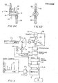
- a cell 1, in which a medium 50 is to be analyzed and contained, is constructed as a glass cylinder 21 having an inside surface on which a cylindrical piezoelectric crystal 18 is provided, and at both ends of which optical windows 19 are provided.
- an excitation beam 100 passes through the optical window 19 and impinges upon the particles 200 included in the medium 50, the particles 200 absorb the beam 100 and emit heat in a relaxation process. Then, by the heat, the medium 50 near the particles 200 is expanded. The expansion of the medium is changed to acoustic waves, and the acoustic waves are detected as - photoacoustic signals by th piezolecytric crystal 18. In this case the nature of the acoustic wave signal does not depend on the kind of excitation beam.
- an excitation beam the power of which is 10 -1 - 10 [w], and modulation frequency of which is 1 2 10 - 10 [HZ], amplitude-modulated to a rectangular wave or sinuosoidal wave 300, is impinged upon the particles in the medium, and a stationary acoustic wave 400 is generated with periodical emission of heat from the particles.
- the radius of the excitation beam is fully greater than that of the particles, and the acoustic wave is generated by a pulsation or oscillation of the whole excitation beam passing region caused by the heat from the particles.
- the heat released into the excitation beam passing region is proportional to the number of atoms and molecules that contribute to the nonradiation excitation and relaxation process, that is, to the concentration of the particles; therefore, the amplitude of the photoacousticc signal is proportional to the concentration of the particles.
- the time from absorption of the excitation beam by the particles to release of heat into the medium near the particles depends on the particle size; therefore, a phase delay of the photoacoustic signal from the impingement timing of the excitation beam to the particles is effected by the particle size. This means that it is possible to determine the particle size in the conventional system even though it is not so practical.
- a focused pulsed beam 500 the power of which is 10 6 - 10 9 [w] and pulse width of which is 10 0 - 10 [ns] is used as excitation rays. Therefore, the particles in the beam path are quickly heated.
- the medium near the particles may be induced to melt, evaporate or even boil if the intensity of the excitation beam is high.
- the medium adjacent to the particles is locally expanded by the heat released from- the particles; then the acoustic pulse is generated. In the present invention, therefore, it is not the whole excitation beam passing region that oscillates, but only the medium adjacent to the particles which becomes a localized sound source; the generated acoustic pulses corespond to the respective particles.
- the period of the excitation beam is preferably set longer than the attenuation time of the acoustic pulse from a particle; no stationary acoustic wave is generated. Therefore, it is possible to count the particle number by counting the acoustic pulses. Since the peak itensity of the acoustic pulse is proportional to the heat quantity released from the particle and the heat quantity depends on the particle size, the particle size can be determined from the peak intensity. Since the time required to release heat from the particle depends on the particle size, the particle size can be determined from the time delay from the impingement of the excitation beam to the appearance of the peak 600 of the acoustic pulse by the particle.
- a photoacoustic signal is generated by the light absorption of the medium itself on the optical window.
- the time required to release heat for boiling or evaporation, such as seen in the particles is not needed, the peak 700 of the photoacoustic pulse from the medium appears faster than that of the particles; therefore, they can be easily distinguished and the photoacoustic pulse by the medium itself can be removed from the processed signal, if necessary.
- the photoacoustic signal generated by soluble matter does not require time to release heat, the photoacoustic signal from the soluble matter appears with the same timing as the acoustic pulse by the medium itself. It is, therefore, possible to determine the quantity or concentration of the soluble matter from the peak intensity of the signal.
- the signals 800 by reverberation continue within the attenuation time of the photoacoustic pulse after the signal 600.
- the acoustic wave P (r, t) generated from a heat source H (r, t) can be given as: wherein ⁇ is the d'Alembertian differential operator, Cp is the specific heat of the medium, ⁇ is the isothermal expansion coefficient of the medium.
- ⁇ is the d'Alembertian differential operator
- Cp is the specific heat of the medium
- ⁇ is the isothermal expansion coefficient of the medium.
- An acoustic wave detector may make use of a piezoelectric effect or optical determination of a density variation or a refraction rate fluctuation of the medium with passage of an acoustic pulse. In the latter case, the output of detection may determine deflection or scattering of the laser beam according to a refraction rate fluctuation.
- Fig. 1 shows a basic block diagram of the present invention.
- a cell 1 contains a medium including particles.
- An example of the cell 1 is shown in Fig. 3.
- An excitation ray source 2 generates excitation rays 100 with predetermined form, output power and period in time.
- a half mirror 3 is placed on the path of the excitation rays from the source 2 to the cell 1 and divides a part of the excitation rays and changes the direction of the divided part.
- An excitation ray monitor 4 detects the divided excitation rays and outputs a time standard signal when the divided excitation rays are detected.
- a signal processor 5 is given two signals; one is an acoustic wave output of the cell 1 and the other is the time standard signal from monitor 4.
- the signal processor 5 detects an acoustic wave form and a delay time from the time standard signal to the peak of the acoustic wave.
- Calculator 6 processes the outputs of th signal processor statistically and calculates a particle size distribution
- the present invention is broadly embodied.
- Fig. 2 shows more detail of the embodiment of Fig. 1.
- Fig. 2 means with the same reference numerals shown in Fig. 1 are the same and operate with the same functions described in Fig. 1.
- An iris diaphragm 17 and the converging lens 8 adjust the average diameter of the excitation beam to be set at a predetermined value.
- a light absorbing cell 9 is provided to absorb light passed through the cell 1.
- the excitation ray source 2 includes a YAG Laser, which outputs a laser beam 100 having 532 nm of wave length and 76.5 mJ of intensity.
- the average diameter of the excitation beam in the cell 1 is 28nm.
- the excitation ray monitor 4 is constructed as a photodiode 10 and preamplifier 11.
- the signal processor 5 includes a boxcar integrator 12, a synchroscope 13 and a recorder 14.
- the boxcar integrator 12 is triggerd by the output of the preamplifier 11 and detects a photoacoustic signal from the cell 1.
- the signal detected by the boxcar integrator l2 is displayed on the synchroscope 13 and is recorded by the recorder 14.
- a computer is used as the calculator 6.
- Fig. 3 shows a sectional view of a batch cell that may be used as the embodiment shown in Figures 1 and 2.
- a cylindrical piezoeffect element 18 is provided on the inside surface of a cylindrical glass 21 and provides two leads 20 to conduct a detected signal to the signal processor 5.
- One of the optical windows 19 is temporarily removed when the medium to be analyzed is introduced into the cell 1.
- Fig. 4 shows a graph of one example of analysis by the embodiment shown in Figures 1 and 2.
- the medium is reagent water that does not include particles larger than 0.1 ⁇ m, and in which polystyrene particles 0.3 um diameter are added as particles to be detected.
- the first peak 600 is an acoustic signal by a particle
- the continuing two peaks 800 are signals by reverberation of the acoustic signal. From Fi g . 4, it is clear to detect the particles of 0.3 ⁇ m by the present invention.
- the particle density is calculated as 3.7 x 10 particles/ml from the volume of the excitation ray passing region (In this case, the length of the cell 1 is 100 mm.).
- the result showed good correspondence with 3 the pre-adjusted value 4.0 x 10 particles/ml.
- a tank 27 is a source of the medium for analyzing particles and feeds a pump 26 to pass the medium to the cell 1.
- the return pipe 32 may not come back to the tank 27 as shown, but rather the medium may be thrown out.
- a half mirror 3' is similar to the mirror 3 and reflects a part of light 100 divided from mirror 3 to a piezoelectric effect element that provides a standard signal corresponding the intensity of the received light.
- An iris diaphragm 17' is similar to the iris diaphragm 17, through which the light passed through the mirror 3' is given to the photodiode 10.
- a preamplifier 11' is similar to the preamplifier 11 and provides an output signal corresponding to the acoustic wave signal given by the cell 1.
- a band-pass filter 22 passes only a signal within a predetermined frequency band consistent with the resonance frequency of the cell 1.
- a peak holder 23 has two channels, chl and ch2; one channel keeps a peak intensity of the standard signal given by the piezoelectric effect element 24 and the other channel keeps a peak intensity of the acoustic wave signal given by the band-pass filter 22.
- a display 25 displays signals processed by the computer 6. An example of the display is shown in Fig. 5 as "Data Example".
- the cell 1 is a flow through cell in Fig. 6A and Fig. 6B. which show a side view and a front view thereof, respectively.
- the cell shown in Figs. 6A and 6B is different only from the one shown in Fig. 3 in that the cell shown in Figs. 6A and 6B provides an inlet pipe 28 to introduce the medium into the cylindrical glass 21 and an outlet pipe 29 to exhaust the medium from the cylindrical glass 21.
- the period for generation of the excitation beam is preferably made longer than an attenuation time of a photoacoustic wave.
- the analyzing should be done in as short as possible a time; the period for generation of the excitation beam may be set substantially the same as preferably somewhat less than an attenuation time of a photoacoustic wave so long as it is possible to distinguish individual photoacoustic waves (resulting from individual particles, respectively) from each other.
- the speed of signal processing in the boxcar integrator may be made higher than that used with of the batch cell.
- the peak holder 23 is useful in the case of the signal processing speed being higher.
- the standard signal corresponding to the intensity of the excitation rays passed to the cell 1 is available for a normalization or a correction of the intensity of the acoustic wave signal detected by the cell 1.
- the intensity of the acoustic wave signal is normalized; in other words, it is changed to the logical value "1" or "0" and it is corrected based upon the detected intensity of the excitation rays before the normalization.
- an acoustic pulse output of 0.2 mv is gotten for a particle size 0.1 ⁇ m; and the number of counts per minute 46 is gotten for a particle density of 100 particles /ml.
Abstract
Description
- The present invention relates to an apparatus and method for analyzing particles in a Medium, by a photoacoustic spectroscopy, more particularly, analyzing submicron order particles in liquids, for example, trace impurities in reagent water.
- Oda et al introduced photoacoustic spectroscopy for analyzing particles in water in "Analysis of Turbid Solutions by Laser-Induced Photoacoustic Spectroscopy" in a magazine, Analytical Chemistry, Vol. 52, No. 4, April 1980. It is known, for an analysis of particles in a medium, to apply photoacoustic spectroscopy. In the conventional system, the concentration of the particles has been determined. The capability of measuring the particle size distribution is suggested, but it is not practical yet.
- In the present invention, the excitation rays, which are a focused and pulsed beam, are impinged upon particles. The period of the pulsed beam is preferably longer than the attenuation time of an acoustic signal that is generated when the pulsed beam impinges upon a particle. Therefore, each of the acoustic signals corresponds to each of the particles, respectively.
- It is an object of the present invention to provide an apparatus and a method that are able to count the number of particles in a medium.
- It is another object of the present invention to provide an apparatus and a method that are able to measure particle sizes in a medium.
- It is another object of the present invention to provide an apparatus and a method that are able to continuously analyze particles in a flowing medium.
- It is another object of the present invention to provide an apparatus and a method that are not affected by Rayleigh Scattering so that it is made to be available to analyze particles of 0.5 um or smaller.
- It is another object of the present invention to provide an apparatus and a method that are able to break or able to divide particles when the excitation rays impinge upon the particles.
-
- Fig. 1 shows a basic block diagram of the present invention.
- Fig. 2 shows a block diagram of the present invention in more detail.
- Fig. 3 shows a sectional view of a cell, which is applicable to the embodiment shown in Figures 1 and 2.
- Fig. 4 shows a graph of one example of an analysis by the embodiment shown in Figures 1 and 2.
- Fig. 5 shows further details of the embodiment of the present invention.
- Figures 6A and 6B show a side view and a front view, respectively, of a cell, which is applicable to the embodiment shown in Figures 1, 2 and 5.
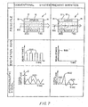
- Fig. 7 depicts a comparison of a conventional system and the present invention.
- First, a comparison of a conventional system and the present invention about the principle, excitation rays, and photoacoustic signals in photoacoustic spectroscopy is described according to Fig. 7.
- A
cell 1, in which amedium 50 is to be analyzed and contained, is constructed as aglass cylinder 21 having an inside surface on which a cylindricalpiezoelectric crystal 18 is provided, and at both ends of whichoptical windows 19 are provided. When anexcitation beam 100 passes through theoptical window 19 and impinges upon theparticles 200 included in themedium 50, theparticles 200 absorb thebeam 100 and emit heat in a relaxation process. Then, by the heat, themedium 50 near theparticles 200 is expanded. The expansion of the medium is changed to acoustic waves, and the acoustic waves are detected as - photoacoustic signals by thpiezolecytric crystal 18. In this case the nature of the acoustic wave signal does not depend on the kind of excitation beam. - In the conventional system, an excitation beam, the power of which is 10-1 - 10 [w], and modulation frequency of which is 1 2 10 - 10 [HZ], amplitude-modulated to a rectangular wave or
sinuosoidal wave 300, is impinged upon the particles in the medium, and a stationaryacoustic wave 400 is generated with periodical emission of heat from the particles. In this case, the radius of the excitation beam is fully greater than that of the particles, and the acoustic wave is generated by a pulsation or oscillation of the whole excitation beam passing region caused by the heat from the particles. The heat released into the excitation beam passing region is proportional to the number of atoms and molecules that contribute to the nonradiation excitation and relaxation process, that is, to the concentration of the particles; therefore, the amplitude of the photoacousticc signal is proportional to the concentration of the particles. Further, the time from absorption of the excitation beam by the particles to release of heat into the medium near the particles depends on the particle size; therefore, a phase delay of the photoacoustic signal from the impingement timing of the excitation beam to the particles is effected by the particle size. This means that it is possible to determine the particle size in the conventional system even though it is not so practical. - J In the present invention, a focused
pulsed beam 500, the power of which is 106 - 109 [w] and pulse width of which is 100 - 10 [ns], is used as excitation rays. Therefore, the particles in the beam path are quickly heated. The medium near the particles may be induced to melt, evaporate or even boil if the intensity of the excitation beam is high. The medium adjacent to the particles is locally expanded by the heat released from- the particles; then the acoustic pulse is generated. In the present invention, therefore, it is not the whole excitation beam passing region that oscillates, but only the medium adjacent to the particles which becomes a localized sound source; the generated acoustic pulses corespond to the respective particles. Further, the period of the excitation beam is preferably set longer than the attenuation time of the acoustic pulse from a particle; no stationary acoustic wave is generated. Therefore, it is possible to count the particle number by counting the acoustic pulses. Since the peak itensity of the acoustic pulse is proportional to the heat quantity released from the particle and the heat quantity depends on the particle size, the particle size can be determined from the peak intensity. Since the time required to release heat from the particle depends on the particle size, the particle size can be determined from the time delay from the impingement of the excitation beam to the appearance of thepeak 600 of the acoustic pulse by the particle. - In the present invention, as in the conventional system, a photoacoustic signal is generated by the light absorption of the medium itself on the optical window. But in the present invention, since the time required to release heat for boiling or evaporation, such as seen in the particles is not needed, the
peak 700 of the photoacoustic pulse from the medium appears faster than that of the particles; therefore, they can be easily distinguished and the photoacoustic pulse by the medium itself can be removed from the processed signal, if necessary. - Since the photoacoustic signal generated by soluble matter does not require time to release heat, the photoacoustic signal from the soluble matter appears with the same timing as the acoustic pulse by the medium itself. It is, therefore, possible to determine the quantity or concentration of the soluble matter from the peak intensity of the signal. The
signals 800 by reverberation continue within the attenuation time of the photoacoustic pulse after thesignal 600. - Generally, the acoustic wave P (r, t) generated from a heat source H (r, t) can be given as:

(r) of the irradiation light is independent of the time distribution M(t) of that, the heat source H(r , t) may be given as:

- An acoustic wave detector may make use of a piezoelectric effect or optical determination of a density variation or a refraction rate fluctuation of the medium with passage of an acoustic pulse. In the latter case, the output of detection may determine deflection or scattering of the laser beam according to a refraction rate fluctuation.
- Fig. 1 shows a basic block diagram of the present invention. A
cell 1 contains a medium including particles. An example of thecell 1 is shown in Fig. 3. Anexcitation ray source 2 generatesexcitation rays 100 with predetermined form, output power and period in time. Ahalf mirror 3 is placed on the path of the excitation rays from thesource 2 to thecell 1 and divides a part of the excitation rays and changes the direction of the divided part. Anexcitation ray monitor 4 detects the divided excitation rays and outputs a time standard signal when the divided excitation rays are detected. Asignal processor 5 is given two signals; one is an acoustic wave output of thecell 1 and the other is the time standard signal frommonitor 4. Thesignal processor 5 detects an acoustic wave form and a delay time from the time standard signal to the peak of the acoustic wave.Calculator 6 processes the outputs of th signal processor statistically and calculates a particle size distribution, if necessary. - According to the basic construction shown in Fig. 1, the present invention is broadly embodied.
- Fig. 2 shows more detail of the embodiment of Fig. 1. In Fig. 2, means with the same reference numerals shown in Fig. 1 are the same and operate with the same functions described in Fig. 1. An
iris diaphragm 17 and the converginglens 8 adjust the average diameter of the excitation beam to be set at a predetermined value. A light absorbing cell 9 is provided to absorb light passed through thecell 1. In Fig. 2, theexcitation ray source 2 includes a YAG Laser, which outputs alaser beam 100 having 532 nm of wave length and 76.5 mJ of intensity. The average diameter of the excitation beam in thecell 1 is 28nm. Theexcitation ray monitor 4 is constructed as aphotodiode 10 and preamplifier 11. Thesignal processor 5 includes aboxcar integrator 12, asynchroscope 13 and arecorder 14. Theboxcar integrator 12 is triggerd by the output of the preamplifier 11 and detects a photoacoustic signal from thecell 1. The signal detected by the boxcar integrator l2is displayed on thesynchroscope 13 and is recorded by therecorder 14. A computer is used as thecalculator 6. - Fig. 3 shows a sectional view of a batch cell that may be used as the embodiment shown in Figures 1 and 2. A
cylindrical piezoeffect element 18 is provided on the inside surface of acylindrical glass 21 and provides two leads 20 to conduct a detected signal to thesignal processor 5. One of theoptical windows 19 is temporarily removed when the medium to be analyzed is introduced into thecell 1. - Fig. 4 shows a graph of one example of analysis by the embodiment shown in Figures 1 and 2. In this case, the medium is reagent water that does not include particles larger than 0.1 µm, and in which polystyrene particles 0.3 um diameter are added as particles to be detected. In Fig. 4, the
first peak 600 is an acoustic signal by a particle, and the continuing twopeaks 800 are signals by reverberation of the acoustic signal. From Fig. 4, it is clear to detect the particles of 0.3 µm by the present invention. - A similar measurement was made of a medium including 0.8 µm particles with known density and showed the result of 460 counts of acoustic pulses after 2,000 impingements to the medium of the excitation beam. In this case, the particle density is calculated as 3.7 x 10 particles/ml from the volume of the excitation ray passing region (In this case, the length of the
cell 1 is 100 mm.). The result showed good correspondence with 3 the pre-adjusted value 4.0 x 10 particles/ml. - Further detail of the embodiment is shown in Fig. 5. The
cell 1 is specifically shown as a continuous flow through cell, although the batch cell of Figure 3 may be used. In Fig. 5, atank 27 is a source of the medium for analyzing particles and feeds apump 26 to pass the medium to thecell 1. Thereturn pipe 32 may not come back to thetank 27 as shown, but rather the medium may be thrown out. A half mirror 3' is similar to themirror 3 and reflects a part of light 100 divided frommirror 3 to a piezoelectric effect element that provides a standard signal corresponding the intensity of the received light. An iris diaphragm 17' is similar to theiris diaphragm 17, through which the light passed through the mirror 3' is given to thephotodiode 10. A preamplifier 11' is similar to the preamplifier 11 and provides an output signal corresponding to the acoustic wave signal given by thecell 1. A band-pass filter 22 passes only a signal within a predetermined frequency band consistent with the resonance frequency of thecell 1. Apeak holder 23 has two channels, chl and ch2; one channel keeps a peak intensity of the standard signal given by thepiezoelectric effect element 24 and the other channel keeps a peak intensity of the acoustic wave signal given by the band-pass filter 22. Adisplay 25 displays signals processed by thecomputer 6. An example of the display is shown in Fig. 5 as "Data Example". - The
cell 1 is a flow through cell in Fig. 6A and Fig. 6B. which show a side view and a front view thereof, respectively. The cell shown in Figs. 6A and 6B is different only from the one shown in Fig. 3 in that the cell shown in Figs. 6A and 6B provides aninlet pipe 28 to introduce the medium into thecylindrical glass 21 and anoutlet pipe 29 to exhaust the medium from thecylindrical glass 21. - In Fig. 5, the signals which are outputs of the
cell 1 and thepiezoelectric effect element 24 corresponding to the intensity of the acoustic wave and the excitation rays, respectively, are given to theboxcar integrator 12 through thepeak holder 23. - In the case of the
cell 1 being a batch cell shown in Fig. 3, it is possible to use a long time for analyzing; then the period for generation of the excitation beam is preferably made longer than an attenuation time of a photoacoustic wave. In the case of thecell 1 being a flow cell shown in Figs. 6A and 6E, however, the analyzing should be done in as short as possible a time; the period for generation of the excitation beam may be set substantially the same as preferably somewhat less than an attenuation time of a photoacoustic wave so long as it is possible to distinguish individual photoacoustic waves (resulting from individual particles, respectively) from each other. The speed of signal processing in the boxcar integrator may be made higher than that used with of the batch cell. Thepeak holder 23 is useful in the case of the signal processing speed being higher. - In the embodiment as shown in Fig. 5, the standard signal corresponding to the intensity of the excitation rays passed to the
cell 1 is available for a normalization or a correction of the intensity of the acoustic wave signal detected by thecell 1. - The intensity of the acoustic wave signal is normalized; in other words, it is changed to the logical value "1" or "0" and it is corrected based upon the detected intensity of the excitation rays before the normalization.
- As a further example, an acoustic pulse output of 0.2 mv is gotten for a particle size 0.1 µm; and the number of counts per minute 46 is gotten for a particle density of 100 particles /ml.
- It is possible to have a higher sensitivity by employing a resonant absorption of particles in a strong electromagnetic field as known in laser fusion (refer to H. Maki et al, Journal of the Physical Society of Japan, 46, 653 (1979)).
- Obviously, many modifications and variations of the present invention are possible in light of the above teachings. Thus, it is to be understood that within the scope of the appended claims, the invention may be practiced.
Claims (18)
wherein said source (2) is setting the predetermined period substantially equal to or longer than the attenuation time of the photoacoustic waves, so that the number of photoacoustic waves corresponds to the number of particles (200) impinged by the rays (100).
said source is setting focusing and the predetermined period of the rays relative to the attenuation time of the photoacoustic waves so that individual photoacoustic waves resulting from individual particles being impinged by the rays are formed and distinguishable from each other;
Applications Claiming Priority (2)
| Application Number | Priority Date | Filing Date | Title |
|---|---|---|---|
| JP60177552A JPS6238345A (en) | 1985-08-14 | 1985-08-14 | Method and instrument for analyzing solid particles |
| JP177552/85 | 1985-08-14 |
Publications (3)
| Publication Number | Publication Date |
|---|---|
| EP0213468A2 true EP0213468A2 (en) | 1987-03-11 |
| EP0213468A3 EP0213468A3 (en) | 1987-07-29 |
| EP0213468B1 EP0213468B1 (en) | 1990-10-24 |
Family
ID=16032945
Family Applications (1)
| Application Number | Title | Priority Date | Filing Date |
|---|---|---|---|
| EP86111073A Expired EP0213468B1 (en) | 1985-08-14 | 1986-08-11 | Apparatus and method for analyzing particles in a medium |
Country Status (4)
| Country | Link |
|---|---|
| US (1) | US4722602A (en) |
| EP (1) | EP0213468B1 (en) |
| JP (1) | JPS6238345A (en) |
| DE (1) | DE3675117D1 (en) |
Cited By (3)
| Publication number | Priority date | Publication date | Assignee | Title |
|---|---|---|---|---|
| EP0336429A2 (en) * | 1988-04-08 | 1989-10-11 | Hitachi, Ltd. | Analytical method for particulate substances, relevant analytical equipment and its application system |
| WO1990009573A1 (en) * | 1989-02-14 | 1990-08-23 | National Research Development Corporation | Apparatus and method for determining powder characteristics |
| WO2008116655A1 (en) * | 2007-03-27 | 2008-10-02 | Fraunhofer-Gesellschaft zur Förderung der angewandten Forschung e.V. | Photoacoustic detector for measuring fine dust |
Families Citing this family (11)
| Publication number | Priority date | Publication date | Assignee | Title |
|---|---|---|---|---|
| JPH0621861B2 (en) * | 1987-09-28 | 1994-03-23 | 株式会社日立製作所 | Photoacoustic spectroscopy |
| JP2543151B2 (en) * | 1988-08-18 | 1996-10-16 | 株式会社日立製作所 | Breakdown plasma measuring device |
| US5069551A (en) * | 1989-11-24 | 1991-12-03 | Iowa State University Research Foundation, Inc. | Method and apparatus of measuring unburned carbon in fly ash |
| DE4130639A1 (en) * | 1991-09-14 | 1993-03-18 | Reinhard Dr Niessner | METHOD FOR THE QUANTITATIVE AND QUALITATIVE DETECTION OF HYDROCARBON-CARBON PARTICLES IN GASES |
| FR2815716B1 (en) * | 2000-10-23 | 2002-11-29 | Commissariat Energie Atomique | DEVICE FOR ONLINE MEASUREMENT OF LASER PULSATIONS AND METHOD OF MEASUREMENT BY PHOTOACOUSTIC SPECTROSCOPY |
| ATE516491T1 (en) * | 2006-11-10 | 2011-07-15 | Koninkl Philips Electronics Nv | PHOTOACOUSTIC DETECTOR WITH IMPROVED SIGNAL PROCESSING |
| FR2920542B1 (en) * | 2007-08-27 | 2010-02-26 | Korea Electric Power Corp | APPARATUS AND METHOD FOR DETECTING PARTICLES CONTAINED IN WATER |
| US8848191B2 (en) | 2012-03-14 | 2014-09-30 | Honeywell International Inc. | Photoacoustic sensor with mirror |
| US11085903B2 (en) * | 2016-06-14 | 2021-08-10 | Nemak S.A.B. De C.V. | Method, device and use for the device for quantitatively determining the concentration or particle size of a component of a heterogeneous material mixture |
| EP3279635B1 (en) * | 2016-08-04 | 2022-06-01 | Malvern Panalytical Limited | Method, processor and machine-readable, non-transient storage medium for characterising particles suspended in a fluid dispersant |
| CN115683959B (en) * | 2022-11-03 | 2023-07-14 | 北京信息科技大学 | System and method for identifying particle size of biomass particles based on collision sound characteristics |
Citations (3)
| Publication number | Priority date | Publication date | Assignee | Title |
|---|---|---|---|---|
| US3710615A (en) * | 1971-03-25 | 1973-01-16 | Trw Inc | Acoustic particle concentration measuring instrument and method |
| US4184768A (en) * | 1977-11-04 | 1980-01-22 | The Johns Hopkins University | Self-calibrating photoacoustic apparatus for measuring light intensity and light absorption |
| DE3319922A1 (en) * | 1983-06-01 | 1984-12-06 | Bayer Ag, 5090 Leverkusen | Method and device for controlling processes in which a disperse phase is involved |
Family Cites Families (2)
| Publication number | Priority date | Publication date | Assignee | Title |
|---|---|---|---|---|
| US4277179A (en) * | 1979-03-12 | 1981-07-07 | The United States Of America As Represented By The Secretary Of The Army | Resonant subcavity differential spectrophone |
| US4413504A (en) * | 1982-05-27 | 1983-11-08 | University Of Florida | Liquid-phase chromatography detector |
-
1985
- 1985-08-14 JP JP60177552A patent/JPS6238345A/en active Granted
-
1986
- 1986-08-01 US US06/894,665 patent/US4722602A/en not_active Expired - Lifetime
- 1986-08-11 DE DE8686111073T patent/DE3675117D1/en not_active Expired - Lifetime
- 1986-08-11 EP EP86111073A patent/EP0213468B1/en not_active Expired
Patent Citations (3)
| Publication number | Priority date | Publication date | Assignee | Title |
|---|---|---|---|---|
| US3710615A (en) * | 1971-03-25 | 1973-01-16 | Trw Inc | Acoustic particle concentration measuring instrument and method |
| US4184768A (en) * | 1977-11-04 | 1980-01-22 | The Johns Hopkins University | Self-calibrating photoacoustic apparatus for measuring light intensity and light absorption |
| DE3319922A1 (en) * | 1983-06-01 | 1984-12-06 | Bayer Ag, 5090 Leverkusen | Method and device for controlling processes in which a disperse phase is involved |
Non-Patent Citations (2)
| Title |
|---|
| ANALYTICAL CHEMISTRY, vol. 52, no. 4, April 1980, pages 650-653, Washington DC, US; S. ODA et al.: "Analysis of turbid solutions by laser-induced photoacoustic spectroscopy" * |
| ANALYTICAL CHEMISTRY, vol. 55, no. 1, January 1983, pages 89A-105A, Easton, Pennsylvania, US; J.F. McCLELLAND "Photoacoustic spectroscopy" * |
Cited By (5)
| Publication number | Priority date | Publication date | Assignee | Title |
|---|---|---|---|---|
| EP0336429A2 (en) * | 1988-04-08 | 1989-10-11 | Hitachi, Ltd. | Analytical method for particulate substances, relevant analytical equipment and its application system |
| EP0336429A3 (en) * | 1988-04-08 | 1990-12-12 | Hitachi, Ltd. | Analytical method for particulate substances, relevant analytical equipment and its application system |
| WO1990009573A1 (en) * | 1989-02-14 | 1990-08-23 | National Research Development Corporation | Apparatus and method for determining powder characteristics |
| WO2008116655A1 (en) * | 2007-03-27 | 2008-10-02 | Fraunhofer-Gesellschaft zur Förderung der angewandten Forschung e.V. | Photoacoustic detector for measuring fine dust |
| US8115931B2 (en) | 2007-03-27 | 2012-02-14 | Fraunhofer-Gesellschaft Zur Foerderung Der Angewandten Forschung E.V. | Photoacoustic detector for measuring fine dust |
Also Published As
| Publication number | Publication date |
|---|---|
| EP0213468A3 (en) | 1987-07-29 |
| JPH0479570B2 (en) | 1992-12-16 |
| JPS6238345A (en) | 1987-02-19 |
| US4722602A (en) | 1988-02-02 |
| DE3675117D1 (en) | 1990-11-29 |
| EP0213468B1 (en) | 1990-10-24 |
Similar Documents
| Publication | Publication Date | Title |
|---|---|---|
| US4722602A (en) | Apparatus and method for analyzing particles in a medium | |
| EP0165711B1 (en) | Method and apparatus for detecting thermal waves | |
| EP0214769B1 (en) | Aerosol particle charge and size analyzer | |
| EP0979111B1 (en) | Optical detection and quantification of microair in blood | |
| US6348968B2 (en) | Photoacoustic spectroscopy apparatus and method | |
| US5365559A (en) | Particle counting apparatus for a total counting of particles contained in a liquid sample | |
| EP0899548B1 (en) | Cross-correlation method and apparatus for suppressing the effects of multiple scattering | |
| Mazumder et al. | SPART analyzer: its application to aerodynamic size distribution measurement | |
| JPH0810188B2 (en) | Particulate matter analyzer and analysis method, ultrapure water production apparatus, semiconductor production apparatus, high-purity gas production apparatus | |
| KR20120013297A (en) | Method and system for analysing solid particles in a medium | |
| EP0840105A1 (en) | Spectroscopic method and apparatus | |
| US4518861A (en) | Method for the continuous measurement of the mass of aerosol particles in gaseous samples and a device for the implementation of the method | |
| US5033851A (en) | Light scattering method and apparatus for detecting particles in liquid sample | |
| JPH0843292A (en) | Detector for measuring luminous intensity of scattered lightwith thin film of colloid-state medium | |
| JPS63139231A (en) | Method for measuring fine particles in liquid | |
| JP3151036B2 (en) | Method and apparatus for detecting submicron particles | |
| US6005662A (en) | Apparatus and method for the measurement and separation of airborne fibers | |
| Quan et al. | Photoacoustic generation in liquids with low optical absorption | |
| US6122054A (en) | Device for measuring the concentration of airborne fibers | |
| JP3184368B2 (en) | Sample evaluation device by ultrasonic vibration measurement | |
| JPS61288139A (en) | Fine particle detecting device | |
| JP2022529308A (en) | Optical fluid velocity measurement | |
| JP2000002648A (en) | Method and apparatus for measurement of breakdown threshold value of fine particles as well as measuring apparatus for fine particles in liquid by using them | |
| JP2000046723A (en) | Method for inspecting function of platelet | |
| SU815619A1 (en) | Method of measuring non-uniformity concentration in liquids |
Legal Events
| Date | Code | Title | Description |
|---|---|---|---|
| PUAI | Public reference made under article 153(3) epc to a published international application that has entered the european phase |
Free format text: ORIGINAL CODE: 0009012 |
|
| AK | Designated contracting states |
Kind code of ref document: A2 Designated state(s): DE FR GB |
|
| PUAL | Search report despatched |
Free format text: ORIGINAL CODE: 0009013 |
|
| AK | Designated contracting states |
Kind code of ref document: A3 Designated state(s): DE FR GB |
|
| 17P | Request for examination filed |
Effective date: 19870731 |
|
| 17Q | First examination report despatched |
Effective date: 19890221 |
|
| GRAA | (expected) grant |
Free format text: ORIGINAL CODE: 0009210 |
|
| AK | Designated contracting states |
Kind code of ref document: B1 Designated state(s): DE FR GB |
|
| REF | Corresponds to: |
Ref document number: 3675117 Country of ref document: DE Date of ref document: 19901129 |
|
| ET | Fr: translation filed | ||
| PLBE | No opposition filed within time limit |
Free format text: ORIGINAL CODE: 0009261 |
|
| STAA | Information on the status of an ep patent application or granted ep patent |
Free format text: STATUS: NO OPPOSITION FILED WITHIN TIME LIMIT |
|
| 26N | No opposition filed | ||
| PGFP | Annual fee paid to national office [announced via postgrant information from national office to epo] |
Ref country code: FR Payment date: 19950718 Year of fee payment: 10 |
|
| PGFP | Annual fee paid to national office [announced via postgrant information from national office to epo] |
Ref country code: GB Payment date: 19950801 Year of fee payment: 10 |
|
| PG25 | Lapsed in a contracting state [announced via postgrant information from national office to epo] |
Ref country code: GB Effective date: 19960811 |
|
| GBPC | Gb: european patent ceased through non-payment of renewal fee |
Effective date: 19960811 |
|
| PG25 | Lapsed in a contracting state [announced via postgrant information from national office to epo] |
Ref country code: FR Effective date: 19970430 |
|
| REG | Reference to a national code |
Ref country code: FR Ref legal event code: ST |
|
| PGFP | Annual fee paid to national office [announced via postgrant information from national office to epo] |
Ref country code: DE Payment date: 20010928 Year of fee payment: 16 |
|
| PG25 | Lapsed in a contracting state [announced via postgrant information from national office to epo] |
Ref country code: DE Free format text: LAPSE BECAUSE OF NON-PAYMENT OF DUE FEES Effective date: 20030301 |