EP0219273A2 - Transparent article having high visible transmittance - Google Patents
Transparent article having high visible transmittance Download PDFInfo
- Publication number
- EP0219273A2 EP0219273A2 EP86307565A EP86307565A EP0219273A2 EP 0219273 A2 EP0219273 A2 EP 0219273A2 EP 86307565 A EP86307565 A EP 86307565A EP 86307565 A EP86307565 A EP 86307565A EP 0219273 A2 EP0219273 A2 EP 0219273A2
- Authority
- EP
- European Patent Office
- Prior art keywords
- layer
- dereflecting
- transparent
- metal
- silver
- Prior art date
- Legal status (The legal status is an assumption and is not a legal conclusion. Google has not performed a legal analysis and makes no representation as to the accuracy of the status listed.)
- Granted
Links
Images

Classifications
-
- C—CHEMISTRY; METALLURGY
- C03—GLASS; MINERAL OR SLAG WOOL
- C03C—CHEMICAL COMPOSITION OF GLASSES, GLAZES OR VITREOUS ENAMELS; SURFACE TREATMENT OF GLASS; SURFACE TREATMENT OF FIBRES OR FILAMENTS MADE FROM GLASS, MINERALS OR SLAGS; JOINING GLASS TO GLASS OR OTHER MATERIALS
- C03C17/00—Surface treatment of glass, not in the form of fibres or filaments, by coating
- C03C17/34—Surface treatment of glass, not in the form of fibres or filaments, by coating with at least two coatings having different compositions
- C03C17/36—Surface treatment of glass, not in the form of fibres or filaments, by coating with at least two coatings having different compositions at least one coating being a metal
- C03C17/3602—Surface treatment of glass, not in the form of fibres or filaments, by coating with at least two coatings having different compositions at least one coating being a metal the metal being present as a layer
- C03C17/3618—Coatings of type glass/inorganic compound/other inorganic layers, at least one layer being metallic
-
- B—PERFORMING OPERATIONS; TRANSPORTING
- B32—LAYERED PRODUCTS
- B32B—LAYERED PRODUCTS, i.e. PRODUCTS BUILT-UP OF STRATA OF FLAT OR NON-FLAT, e.g. CELLULAR OR HONEYCOMB, FORM
- B32B7/00—Layered products characterised by the relation between layers; Layered products characterised by the relative orientation of features between layers, or by the relative values of a measurable parameter between layers, i.e. products comprising layers having different physical, chemical or physicochemical properties; Layered products characterised by the interconnection of layers
- B32B7/02—Physical, chemical or physicochemical properties
-
- C—CHEMISTRY; METALLURGY
- C03—GLASS; MINERAL OR SLAG WOOL
- C03C—CHEMICAL COMPOSITION OF GLASSES, GLAZES OR VITREOUS ENAMELS; SURFACE TREATMENT OF GLASS; SURFACE TREATMENT OF FIBRES OR FILAMENTS MADE FROM GLASS, MINERALS OR SLAGS; JOINING GLASS TO GLASS OR OTHER MATERIALS
- C03C17/00—Surface treatment of glass, not in the form of fibres or filaments, by coating
- C03C17/34—Surface treatment of glass, not in the form of fibres or filaments, by coating with at least two coatings having different compositions
- C03C17/36—Surface treatment of glass, not in the form of fibres or filaments, by coating with at least two coatings having different compositions at least one coating being a metal
- C03C17/3602—Surface treatment of glass, not in the form of fibres or filaments, by coating with at least two coatings having different compositions at least one coating being a metal the metal being present as a layer
- C03C17/3642—Surface treatment of glass, not in the form of fibres or filaments, by coating with at least two coatings having different compositions at least one coating being a metal the metal being present as a layer the multilayer coating containing a metal layer
-
- C—CHEMISTRY; METALLURGY
- C03—GLASS; MINERAL OR SLAG WOOL
- C03C—CHEMICAL COMPOSITION OF GLASSES, GLAZES OR VITREOUS ENAMELS; SURFACE TREATMENT OF GLASS; SURFACE TREATMENT OF FIBRES OR FILAMENTS MADE FROM GLASS, MINERALS OR SLAGS; JOINING GLASS TO GLASS OR OTHER MATERIALS
- C03C17/00—Surface treatment of glass, not in the form of fibres or filaments, by coating
- C03C17/34—Surface treatment of glass, not in the form of fibres or filaments, by coating with at least two coatings having different compositions
- C03C17/36—Surface treatment of glass, not in the form of fibres or filaments, by coating with at least two coatings having different compositions at least one coating being a metal
- C03C17/3602—Surface treatment of glass, not in the form of fibres or filaments, by coating with at least two coatings having different compositions at least one coating being a metal the metal being present as a layer
- C03C17/3652—Surface treatment of glass, not in the form of fibres or filaments, by coating with at least two coatings having different compositions at least one coating being a metal the metal being present as a layer the coating stack containing at least one sacrificial layer to protect the metal from oxidation
-
- C—CHEMISTRY; METALLURGY
- C03—GLASS; MINERAL OR SLAG WOOL
- C03C—CHEMICAL COMPOSITION OF GLASSES, GLAZES OR VITREOUS ENAMELS; SURFACE TREATMENT OF GLASS; SURFACE TREATMENT OF FIBRES OR FILAMENTS MADE FROM GLASS, MINERALS OR SLAGS; JOINING GLASS TO GLASS OR OTHER MATERIALS
- C03C17/00—Surface treatment of glass, not in the form of fibres or filaments, by coating
- C03C17/34—Surface treatment of glass, not in the form of fibres or filaments, by coating with at least two coatings having different compositions
- C03C17/36—Surface treatment of glass, not in the form of fibres or filaments, by coating with at least two coatings having different compositions at least one coating being a metal
- C03C17/3602—Surface treatment of glass, not in the form of fibres or filaments, by coating with at least two coatings having different compositions at least one coating being a metal the metal being present as a layer
- C03C17/3657—Surface treatment of glass, not in the form of fibres or filaments, by coating with at least two coatings having different compositions at least one coating being a metal the metal being present as a layer the multilayer coating having optical properties
- C03C17/366—Low-emissivity or solar control coatings
-
- C—CHEMISTRY; METALLURGY
- C03—GLASS; MINERAL OR SLAG WOOL
- C03C—CHEMICAL COMPOSITION OF GLASSES, GLAZES OR VITREOUS ENAMELS; SURFACE TREATMENT OF GLASS; SURFACE TREATMENT OF FIBRES OR FILAMENTS MADE FROM GLASS, MINERALS OR SLAGS; JOINING GLASS TO GLASS OR OTHER MATERIALS
- C03C17/00—Surface treatment of glass, not in the form of fibres or filaments, by coating
- C03C17/34—Surface treatment of glass, not in the form of fibres or filaments, by coating with at least two coatings having different compositions
- C03C17/36—Surface treatment of glass, not in the form of fibres or filaments, by coating with at least two coatings having different compositions at least one coating being a metal
- C03C17/3602—Surface treatment of glass, not in the form of fibres or filaments, by coating with at least two coatings having different compositions at least one coating being a metal the metal being present as a layer
- C03C17/3668—Surface treatment of glass, not in the form of fibres or filaments, by coating with at least two coatings having different compositions at least one coating being a metal the metal being present as a layer the multilayer coating having electrical properties
- C03C17/3673—Surface treatment of glass, not in the form of fibres or filaments, by coating with at least two coatings having different compositions at least one coating being a metal the metal being present as a layer the multilayer coating having electrical properties specially adapted for use in heating devices for rear window of vehicles
-
- C—CHEMISTRY; METALLURGY
- C03—GLASS; MINERAL OR SLAG WOOL
- C03C—CHEMICAL COMPOSITION OF GLASSES, GLAZES OR VITREOUS ENAMELS; SURFACE TREATMENT OF GLASS; SURFACE TREATMENT OF FIBRES OR FILAMENTS MADE FROM GLASS, MINERALS OR SLAGS; JOINING GLASS TO GLASS OR OTHER MATERIALS
- C03C17/00—Surface treatment of glass, not in the form of fibres or filaments, by coating
- C03C17/34—Surface treatment of glass, not in the form of fibres or filaments, by coating with at least two coatings having different compositions
- C03C17/36—Surface treatment of glass, not in the form of fibres or filaments, by coating with at least two coatings having different compositions at least one coating being a metal
- C03C17/3602—Surface treatment of glass, not in the form of fibres or filaments, by coating with at least two coatings having different compositions at least one coating being a metal the metal being present as a layer
- C03C17/3681—Surface treatment of glass, not in the form of fibres or filaments, by coating with at least two coatings having different compositions at least one coating being a metal the metal being present as a layer the multilayer coating being used in glazing, e.g. windows or windscreens
-
- G—PHYSICS
- G02—OPTICS
- G02B—OPTICAL ELEMENTS, SYSTEMS OR APPARATUS
- G02B5/00—Optical elements other than lenses
- G02B5/20—Filters
- G02B5/28—Interference filters
-
- C—CHEMISTRY; METALLURGY
- C03—GLASS; MINERAL OR SLAG WOOL
- C03C—CHEMICAL COMPOSITION OF GLASSES, GLAZES OR VITREOUS ENAMELS; SURFACE TREATMENT OF GLASS; SURFACE TREATMENT OF FIBRES OR FILAMENTS MADE FROM GLASS, MINERALS OR SLAGS; JOINING GLASS TO GLASS OR OTHER MATERIALS
- C03C2217/00—Coatings on glass
- C03C2217/70—Properties of coatings
- C03C2217/73—Anti-reflective coatings with specific characteristics
- C03C2217/734—Anti-reflective coatings with specific characteristics comprising an alternation of high and low refractive indexes
Definitions
- the invention relates to a transparent article suitable for use in a window and particularly to an electrically conductive coating for windows of motor vehicles where it is necessary to remove ice or fog.
- Partially transparent coatings comprising a thin metal layer between two dielectric anti-reflection layers have many applications, including solar heat rejecting windows for buildings and vehicles. Electrically conductive coatings capable of heating the window to remove ice or fog are particularly desirable. Coatings having uniform, high conductivity and uniform transmittance of greater than 70% are needed for heated windshield applications.
- U.K. Patent 1 307 642 to Asahi Glass Co. discloses an electrically heated window having a dielectric-metal-dielectric coating wherein the metal layer is silver and the dielectric layers are TiU 2 , SnO, or 8i203 among others.
- U.S. Patent 4,368,945 to Fujimori et al discloses an infrared reflecting laminated window comprising a plastic film on which is deposited a dielectric-metal-dielectric coating of tungsten oxide, silver and tungsten oxide.
- U.S. Patent 4,462,883 to Hart discloses a dielectric-metal-dielectric coating for glass or plastic windows comprising a layer of silver between two anti-reflection layers of Sn0 or other metal oxide.
- the silver layer In order not to oxidise the silver layer, it is coated with a small amount of titanium or other sacrificial metal which is oxidized during reactive sputtering of the overlaying metal oxide layer.
- the resulting coated article has a low emissivity i.e., it transmits visible radiation but reflects a high proportion of the incident infrared radiation.
- a particular method for depositing coatings comprising layers of silver and a sacrificial metal oxide are described in U.S. Patent 4,497,700 to Groth et al.
- U.S. Patent 4,337,990 to Fan et al. discloses a transparent heat mirror comprising a layer of sputtered silver sandwiched between layers of reactively sputtered titanium dioxide.
- Laminated glass containing a dielectric-metal-dielectric coating of Ti0 2 -Ag-Ti0 2 has high visible transmittance, high infrared reflection and other superior optical properties.
- titanium dioxide forms at a relatively slow rate by reactive sputtering; the rate is only about 8% of that for zinc oxide or tin oxide.
- glass having a coating of Zn0 - Ag - Zn0 was laminated by us with a layer of plastic and glass by conventional techniques, the transmittance decreased by a surprisingly large amount.
- the resulting transmittance is only slightly greater than required for windshield applications and unusual care is required to produce it in commercial quantitites.
- the present invention aims at providing an article, including dielectric-metal-dielectric layers, having optical properties suitable for heated windshields and other applications which is able to be produced in commercial quantities at a reasonable cost and a process for making the article.
- the invention is directed in one aspect to a transparent article comprising a base, at least four coated layers, and a top protective layer and is defined in claims 1 to 10 of the appended claims.
- the invention also provides a process for making the article as claimed in claims 11 to 14 of the appended claims.
- the coated layers typically include a first dereflecting region, a transparent layer of silver or other metal, and a second dereflecting region comprising a layer of titanium dioxide, Ti0 2 , and a layer of another dielectric material.
- a titanium dioxide layer may also be a component of the first dereflecting region.
- Each deflecting region that includes a titanium dioxide layer also comprises a layer of a transparent oxide or other dielectric material having an index of refraction intermediate between about 2.7, the approximate index of titanium dioxide, and the index of the nearby base or top layer, respectively.
- the intermediate index material is preferably zinc oxide because this material can be relatively quickly and inexpensively deposited by reactive sputtering.
- Bismuth oxide, indium oxide, tin oxide, silicon monoxide and other materials may be used for the intermediate index layers.
- a mixed oxide such as indium-tin oxide, or a composite of two or more layers may be used.
- the metal layer has a resistivity of less than 5 ohms/square.
- the preferred metal is silver, because of its neutral color and high electrical conductivity, but copper, gold or aluminum may be used in less critical applications.
- the transparent substrate or base material 11 is typically glass or plastic having a refractive index of about 1.5. and may be 2.5 mm thick, soda-lime-silica float glass may be used as the base material 11.
- the base is coated with a first transparent, dereflecting layer 12, preferably deposited by reactive sputtering of a metal.
- the layer may comprise 30 to 60 nm of zinc oxide having an index of approximately 2.0.
- a metallic layer 14 having a thickness of 10 to 50 nm; silver having a thickness of 15 to 20 nm is particularly preferred.
- a layer of titanium oxide 16 having a thickness of 2 to 5 nm and preferably formed by oxidizing a metallic titanium layer and then depositing additional titanium dioxide by reactive sputtering.
- Layer 16 is followed by a layer 18 having an index of refraction intermediate between that of a top layer 19 and 2.7 which is the refractive index of titanium dioxide.
- This layer 18 may be zinc oxide of the same or less thickness as the layer 12.
- the top layer 19 is a layer of transparent glass or plastic, typically having an index of about 1.5.
- FIG. 2 illustrates an alternative embodiment specifically designed as an electrically heated window.
- the substrate 11 is a sheet of glass that is partially covered by a pattern of electrically conductive material 21 which serves as an electrode to enable current to be transmitted to a metallic layer 14.
- the first dereflecting region comprises a layer of zinc oxide 22 and may also comprise a layer 23 of titanium dioxide. If included, the titanium dioxide layer 23 is adjacent a metallic layer 14 of silver.
- the silver layer is covered with a thin layer 25 of sacrificial metal which serves to protect the underlying silver layer from oxidation. Because of its great affinity for oxygen, titanium is preferred, but aluminum, zinc, bismuth, indium, tin and other metals are also suitable.
- This dereflecting region also includes a layer 26 of titanium dioxide and a second intermediate index layer 18, preferably of zinc oxide.
- the top layer comprises a sheet of plastic 27 and a sheet of glass 29.
- the preferred embodiment has an electrical resistivity of 4 to 5 ohms/square.
- the optical transmittance is greater than 70% and preferably greater than 72% with low absorption. Refractive indices in the range 2.5 to 2.7 have been measured for the titanium dioxide layer.
- composition of a particularly preferred embodiment is shown in Table 1.
- the glass layers 11 and 19 are each 2.5mm thick, but this thickness is not critical.
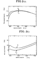
- Curves 1 in Figures 3a and 3b show the spectral transmittance and reflectance of Example 1, a three layer coating of 40 nm zinc oxide, 18 nm silver, and 40 nm zinc oxide on a glass substrate and covered with a top layer of glass.
- Curves 2 show the spectral properties of Example 2, the embodiment of the invention described in Table 1. It is significant that the embodiment of the invention has high transmittance in the visible spectral region and a high reflectance in the near infra-red.
- T l and R l refer to the transmittance and reflectance of the coated base before the top layer is applied.
- T 2 , R 2 and R 3 correspond to the transmittance and reflectance of the laminated article including top layer 19.
- R 2 and R 3 refer to the reflectance for light incidence on base 11 and top layer 19, respectively.
- the final column gives the emissivity e of the article.
- Low emissivity is a measure of high infrared reflectivity and emissivities of 0.15 or less are preferred for solar heat rejecting windows; values of 0.1 or less are especially preferred.
- Example 2 provides higher visible transmittance T 2 . lower reflectances R 2 and R 3 , and substantially the same emissivity e.
- the third row of Table 2 shows the corresponding optical properies of a coating of 33 nm zinc oxide, 3.5 nm titanium dioxide, 18 nm silver, 3 nm titanium dioxide and 33 nm zinc oxide.
- the fourth row of Table 2 shows corresponding optical properties for a coating of 30 nm titanium dioxide, 18 nm silver and 30 nm titanium dioxide.
- FIG. 3 shows a plan view of an apparatus suitable for depositing the coated layers.
- the coating machine comprises sputtering sources 1-5, preferably of the planar magnetron type, an evacuable chamber 6 for providing a suitable low pressure sputtering environment, and a conveyor 8 for transporting substrates through the machine past the sputtering sources.
- the conveyor is a series of motor driven rollers 9 which extends from the entrance through all of the chambers to the exit of the machine.
- the rollers inside the machine are omitted from Fig. 4.
- a side view of a somewhat similar machine is shown in Fig. 1 of U.S. patent 3,945,903 to Svendor et al.
- the substrates to be coated are placed on the conveyor 8 and moved to the external gate 32 of an entrance lock 30.
- the entrance lock enables the low pressure environment of the processing chamber 40 to be maintained by having the interior gate closed 34 while the exterior gate 32 is opened to transport substrates into the lock 30.
- the external gate is closed and the chamber 30 rapidly evacuated.
- the lock is pumped to about 60 mT by a Roots type mechanical pump 35 backed by three mechanical pumps operating in parallel.
- the pressure is lowered further by switching to pumping through a plenum 36 fitted with two diffusion pumps and two air-activated poppet valves 38.
- the plenum is also fitted with mechanically refrigerated cold traps for removing water vapor.
- Buffer section 42 has two plenums 43 each containing three diffusion pumps and associated poppet valves.
- the five sputtering sources 1-5 are preferably planar magnetron sources of the type described in U.S. Patent 4,166,018 of John S. Chapin, assigned to the assignee of the present application.
- the sputtering zone is evacuated via the plenums 43 and 49 connected to the two buffer sections.
- One sputtering gas usually argon, is provided from a supply 62 connected to the process chamber via a first valve.
- a reactive sputtering gas usually oxygen, enters the processing chamber via a second valve from a second supply 64.
- the substrates are transported from the entry buffer past the series of sputtering sources, one or more of which are activated by individual power sources 45.
- the substrates are transported to the exit buffer section 48 which is fitted with two pumping plenums 49 similar to those of the entry buffer section.
- the sputter gas is changed and the substrates are passed back and forth through the sputtering zone 46 as necessary to deposit the required layers in the order desired.
- a second interior gate 52 is opened and the substrates transported into an exit lock 50. After the interior gate is closed and the lock 50 is vented to the atmosphere, the substrates are removed via a second external gate 54.
- the empty exit lock is then evacuated by pumps 55, 56 similar to those of the entry lock 30.
- the gas supply valves, the sputtering power supplies, the gate valves, the conveyor and other operable elements of the coating apparatus may be automatically or manually controlled by conventional means, as desired. Further, means can be provided for washing, rinsing, drying and inspecting the substrates before they are coated.
- Targets of the appropriate materials must first be installed on the sputtering sources in the processing chamber.
- titanium and silver cathodes may be installed in positions 1 and 3, respectively, and zinc targets may be installed in positions 2. 4 and 5.
- High purity target materials (99.95% Ag, 99.95% Zn and 99.8% Ti) are preferred for best results in heated windshield applications but lower purity materials may be suitable in some applications.
- Glass windshields or other suitable substrates are cleaned, loaded onto the conveyor and transported into the processing apparatus. In a first pass, moving to the right in Fig.
- a layer of zinc oxide is deposited by applying power to only the three zinc sputtering sources and introducing a mixture of 95% oxygen and 5% argon into the chamber to maintain a pressure of approximately 2 mT.
- the sputtering power and transport speed are adjusted to produce the desired thickness.
- a puwer of 79 kW applied to each of the three sputtering sources can produce a zinc oxide layer of approximately 37 nm thickness on substrates moving at the rate of 0.16 m/sec.
- Thin layers of silver followed by titanium are deposited on the zinc oxide layer by changing to a non-reactive sputtering gas and transporting the substrates in the reverse direction, back towards the left in Figure 3.
- a power of 17 kw applied to the silver sputtering source in position 3 and a power of 14 kW applied to the titanium sputtering source in position 1 thicknesses of 18 nm Ag and 2 nm Ti are deposited with a conveyor speed of 0.25 m/sec. If necessary to eliminate oxygen, the titanium source can be operated for a time just before the substrates are conveyed through the sputtering zone.
- the titanium layer is oxidized and this material coated with additional titanium dioxide and then zinc oxide on a third pass, moving towards the right in Figure 3.
- an atmosphere of 95% oxygen and 5% argon at a pressure of about 2 mT is maintained, and a power of 90 kw is applied to the titanium cathode in position 1 and a power of 79 kw is applied to each of the three zinc sources.
- This is sufficient to deposit a 1 nm layer of titanium dioxide and a 35 nm layer of zinc oxide on substrates travelling at the rate of 0.14 m/sec.
- the sacrificial metal covering the silver layer is titanium, it is readily incorporated into the titanium dioxide layer. Exact stoichiometry is not critical.
- the coated glass may then be assembled into a laminated windshield by covering the coating with a layer of plastic and then a layer of glass by conventional techniques. Normally, the windshield is installed with the top layer towards the interior of the vehicle. Alternatively, other deposited layers may be applied to the coated base. These additional layers could be a transparent hard material which will provide a scratch-resistant, protective coating. Such additional layers could be deposited by additional sputtering steps in the processing chamber or by other means.
Abstract
Description
- The invention relates to a transparent article suitable for use in a window and particularly to an electrically conductive coating for windows of motor vehicles where it is necessary to remove ice or fog.
- Partially transparent coatings comprising a thin metal layer between two dielectric anti-reflection layers have many applications, including solar heat rejecting windows for buildings and vehicles. Electrically conductive coatings capable of heating the window to remove ice or fog are particularly desirable. Coatings having uniform, high conductivity and uniform transmittance of greater than 70% are needed for heated windshield applications.
- U.K.
Patent 1 307 642 to Asahi Glass Co. discloses an electrically heated window having a dielectric-metal-dielectric coating wherein the metal layer is silver and the dielectric layers are TiU2, SnO, or 8i203 among others. - U.S. Patent 4,368,945 to Fujimori et al discloses an infrared reflecting laminated window comprising a plastic film on which is deposited a dielectric-metal-dielectric coating of tungsten oxide, silver and tungsten oxide.
- U.S. Patent 4,462,883 to Hart discloses a dielectric-metal-dielectric coating for glass or plastic windows comprising a layer of silver between two anti-reflection layers of Sn0 or other metal oxide. In order not to oxidise the silver layer, it is coated with a small amount of titanium or other sacrificial metal which is oxidized during reactive sputtering of the overlaying metal oxide layer. The resulting coated article has a low emissivity i.e., it transmits visible radiation but reflects a high proportion of the incident infrared radiation. A particular method for depositing coatings comprising layers of silver and a sacrificial metal oxide are described in U.S. Patent 4,497,700 to Groth et al.
- U.S. Patent 4,337,990 to Fan et al. discloses a transparent heat mirror comprising a layer of sputtered silver sandwiched between layers of reactively sputtered titanium dioxide.
- Laminated glass containing a dielectric-metal-dielectric coating of Ti02-Ag-Ti02 has high visible transmittance, high infrared reflection and other superior optical properties. Unfortunately, titanium dioxide forms at a relatively slow rate by reactive sputtering; the rate is only about 8% of that for zinc oxide or tin oxide. However, when glass having a coating of Zn0 - Ag - Zn0 was laminated by us with a layer of plastic and glass by conventional techniques, the transmittance decreased by a surprisingly large amount.
- The resulting transmittance is only slightly greater than required for windshield applications and unusual care is required to produce it in commercial quantitites.
- The present invention aims at providing an article, including dielectric-metal-dielectric layers, having optical properties suitable for heated windshields and other applications which is able to be produced in commercial quantities at a reasonable cost and a process for making the article.
- The invention is directed in one aspect to a transparent article comprising a base, at least four coated layers, and a top protective layer and is defined in
claims 1 to 10 of the appended claims. The invention also provides a process for making the article as claimed inclaims 11 to 14 of the appended claims. The coated layers typically include a first dereflecting region, a transparent layer of silver or other metal, and a second dereflecting region comprising a layer of titanium dioxide, Ti02, and a layer of another dielectric material. A titanium dioxide layer may also be a component of the first dereflecting region. Each deflecting region that includes a titanium dioxide layer also comprises a layer of a transparent oxide or other dielectric material having an index of refraction intermediate between about 2.7, the approximate index of titanium dioxide, and the index of the nearby base or top layer, respectively. The intermediate index material is preferably zinc oxide because this material can be relatively quickly and inexpensively deposited by reactive sputtering. Bismuth oxide, indium oxide, tin oxide, silicon monoxide and other materials may be used for the intermediate index layers. If desired, a mixed oxide such as indium-tin oxide, or a composite of two or more layers may be used. Preferably, the metal layer has a resistivity of less than 5 ohms/square. The preferred metal is silver, because of its neutral color and high electrical conductivity, but copper, gold or aluminum may be used in less critical applications. - The invention will now be described by way of example with reference to the accompanying drawings, in which
- Fig. 1 is a cross-sectional view of a transparent article according to the present invention.
- Fig. 2 is a cross-sectional view of another embodiment of the invention.
- Figs. 3a and 3b are graphs illustrating the spectral transmittance and reflectance of a comparison coating (curves 1) and of a preferred embodiment (curves 2).
- Fig 4 is a plan view of an apparatus for making transparent articles according to the invention.
- One preferred embodiment of the invention is illustrated in Figure 1. The transparent substrate or
base material 11 is typically glass or plastic having a refractive index of about 1.5. and may be 2.5 mm thick, soda-lime-silica float glass may be used as thebase material 11. The base is coated with a first transparent,dereflecting layer 12, preferably deposited by reactive sputtering of a metal. The layer may comprise 30 to 60 nm of zinc oxide having an index of approximately 2.0. Next, is ametallic layer 14 having a thickness of 10 to 50 nm; silver having a thickness of 15 to 20 nm is particularly preferred. Next is a layer oftitanium oxide 16, having a thickness of 2 to 5 nm and preferably formed by oxidizing a metallic titanium layer and then depositing additional titanium dioxide by reactive sputtering.Layer 16 is followed by alayer 18 having an index of refraction intermediate between that of atop layer 19 and 2.7 which is the refractive index of titanium dioxide. Thislayer 18 may be zinc oxide of the same or less thickness as thelayer 12. Thetop layer 19 is a layer of transparent glass or plastic, typically having an index of about 1.5. - Figure 2 illustrates an alternative embodiment specifically designed as an electrically heated window. The
substrate 11 is a sheet of glass that is partially covered by a pattern of electrically conductive material 21 which serves as an electrode to enable current to be transmitted to ametallic layer 14. The first dereflecting region comprises a layer ofzinc oxide 22 and may also comprise alayer 23 of titanium dioxide. If included, thetitanium dioxide layer 23 is adjacent ametallic layer 14 of silver. The silver layer is covered with athin layer 25 of sacrificial metal which serves to protect the underlying silver layer from oxidation. Because of its great affinity for oxygen, titanium is preferred, but aluminum, zinc, bismuth, indium, tin and other metals are also suitable. Most of the sacrificial metal is converted to an oxide which forms a part of a second dereflecting region. This dereflecting region also includes alayer 26 of titanium dioxide and a secondintermediate index layer 18, preferably of zinc oxide. The top layer comprises a sheet ofplastic 27 and a sheet ofglass 29. - The preferred embodiment has an electrical resistivity of 4 to 5 ohms/square. The optical transmittance is greater than 70% and preferably greater than 72% with low absorption. Refractive indices in the range 2.5 to 2.7 have been measured for the titanium dioxide layer.
- The composition of a particularly preferred embodiment is shown in Table 1. The
glass layers 
Curves 1 in Figures 3a and 3b show the spectral transmittance and reflectance of Example 1, a three layer coating of 40 nm zinc oxide, 18 nm silver, and 40 nm zinc oxide on a glass substrate and covered with a top layer of glass.Curves 2 show the spectral properties of Example 2, the embodiment of the invention described in Table 1. It is significant that the embodiment of the invention has high transmittance in the visible spectral region and a high reflectance in the near infra-red. - Spectrally averaged (Illuminate A) optical properties are summarized in Table 2. Tl and Rl refer to the transmittance and reflectance of the coated base before the top layer is applied. T2, R2 and R3 correspond to the transmittance and reflectance of the laminated article including
top layer 19. R2 and R3 refer to the reflectance for light incidence onbase 11 andtop layer 19, respectively. The final column gives the emissivity e of the article. Low emissivity is a measure of high infrared reflectivity and emissivities of 0.15 or less are preferred for solar heat rejecting windows; values of 0.1 or less are especially preferred. - For comparison, the first two rows of Table 2 give the optical properties of Examples 1 and 2. Note that the invention, Example 2, provides higher visible transmittance T2. lower reflectances R2 and R3, and substantially the same emissivity e.
- The third row of Table 2 shows the corresponding optical properies of a coating of 33 nm zinc oxide, 3.5 nm titanium dioxide, 18 nm silver, 3 nm titanium dioxide and 33 nm zinc oxide.
- For further comparison, the fourth row of Table 2 shows corresponding optical properties for a coating of 30 nm titanium dioxide, 18 nm silver and 30 nm titanium dioxide.

- As indicate in Table 2, all four Examples have closely similar T1, and emissivity e, but the two embodiments of the invention, Examples 2 and 3, have transniittances T2 ana reflectances R2 and R3 intermediate between Examples 1 and 4 for which the dereflecting layers are exclusively Zn0 or TiO2, respectively. Since an automobile windshield is currently required to have a transmittance T2 of at least 70%, the increase in T2 from 72% (Example 1) to 74% (Example 2) is commercially significant because it provides a margin for reasonable tolerances at all steps of the manufacturing process.
- Certain characteristics of materials which are suitable for sputtering in accordance with the present convention are shown in Table 3. These properties include the melting point (M.P.), approximate cost and index refraction of the indicated oxides. Generally, higher melting point materials enable higher deposition rates because more power can be supplied to the sputtering source without softening or deforming the sputtering target.

rollers 9 which extends from the entrance through all of the chambers to the exit of the machine. The rollers inside the machine are omitted from Fig. 4. A side view of a somewhat similar machine is shown in Fig. 1 of U.S. patent 3,945,903 to Svendor et al. - The substrates to be coated are placed on the conveyor 8 and moved to the
external gate 32 of anentrance lock 30. The entrance lock enables the low pressure environment of theprocessing chamber 40 to be maintained by having the interior gate closed 34 while theexterior gate 32 is opened to transport substrates into thelock 30. When the desired number of substrates are positioned in the lock, the external gate is closed and thechamber 30 rapidly evacuated. The lock is pumped to about 60 mT by a Roots type mechanical pump 35 backed by three mechanical pumps operating in parallel. The pressure is lowered further by switching to pumping through aplenum 36 fitted with two diffusion pumps and two air-activatedpoppet valves 38. The plenum is also fitted with mechanically refrigerated cold traps for removing water vapor. After the entry lock is evacuated to a pressure of approximately 0.1 mT, theinterior gate 34 is opened and the substrates moved from theentry lock 30 into anentry buffer section 42.Buffer section 42 has two plenums 43 each containing three diffusion pumps and associated poppet valves. - The five sputtering sources 1-5 are preferably planar magnetron sources of the type described in U.S. Patent 4,166,018 of John S. Chapin, assigned to the assignee of the present application. The sputtering zone is evacuated via the
plenums 43 and 49 connected to the two buffer sections. One sputtering gas, usually argon, is provided from asupply 62 connected to the process chamber via a first valve. A reactive sputtering gas, usually oxygen, enters the processing chamber via a second valve from asecond supply 64. - When all is ready, the substrates are transported from the entry buffer past the series of sputtering sources, one or more of which are activated by
individual power sources 45. The substrates are transported to theexit buffer section 48 which is fitted with two pumpingplenums 49 similar to those of the entry buffer section. The sputter gas is changed and the substrates are passed back and forth through thesputtering zone 46 as necessary to deposit the required layers in the order desired. When the coating is completed, a secondinterior gate 52 is opened and the substrates transported into anexit lock 50. After the interior gate is closed and thelock 50 is vented to the atmosphere, the substrates are removed via a second external gate 54. The empty exit lock is then evacuated bypumps entry lock 30. - The gas supply valves, the sputtering power supplies, the gate valves, the conveyor and other operable elements of the coating apparatus may be automatically or manually controlled by conventional means, as desired. Further, means can be provided for washing, rinsing, drying and inspecting the substrates before they are coated.
- A process for producing a particular coating will now be described. Targets of the appropriate materials must first be installed on the sputtering sources in the processing chamber. For example, titanium and silver cathodes may be installed in
positions positions 2. 4 and 5. High purity target materials (99.95% Ag, 99.95% Zn and 99.8% Ti) are preferred for best results in heated windshield applications but lower purity materials may be suitable in some applications. Glass windshields or other suitable substrates are cleaned, loaded onto the conveyor and transported into the processing apparatus. In a first pass, moving to the right in Fig. 4, a layer of zinc oxide is deposited by applying power to only the three zinc sputtering sources and introducing a mixture of 95% oxygen and 5% argon into the chamber to maintain a pressure of approximately 2 mT. The sputtering power and transport speed are adjusted to produce the desired thickness. - For example, a puwer of 79 kW applied to each of the three sputtering sources can produce a zinc oxide layer of approximately 37 nm thickness on substrates moving at the rate of 0.16 m/sec.
- Thin layers of silver followed by titanium are deposited on the zinc oxide layer by changing to a non-reactive sputtering gas and transporting the substrates in the reverse direction, back towards the left in Figure 3. With an argon atmosphere of 3 mT, a power of 17 kw applied to the silver sputtering source in
position 3 and a power of 14 kW applied to the titanium sputtering source inposition 1, thicknesses of 18 nm Ag and 2 nm Ti are deposited with a conveyor speed of 0.25 m/sec. If necessary to eliminate oxygen, the titanium source can be operated for a time just before the substrates are conveyed through the sputtering zone. - The titanium layer is oxidized and this material coated with additional titanium dioxide and then zinc oxide on a third pass, moving towards the right in Figure 3. Typically, an atmosphere of 95% oxygen and 5% argon at a pressure of about 2 mT is maintained, and a power of 90 kw is applied to the titanium cathode in
position 1 and a power of 79 kw is applied to each of the three zinc sources. This is sufficient to deposit a 1 nm layer of titanium dioxide and a 35 nm layer of zinc oxide on substrates travelling at the rate of 0.14 m/sec. When the sacrificial metal covering the silver layer is titanium, it is readily incorporated into the titanium dioxide layer. Exact stoichiometry is not critical. - The coated glass may then be assembled into a laminated windshield by covering the coating with a layer of plastic and then a layer of glass by conventional techniques. Normally, the windshield is installed with the top layer towards the interior of the vehicle. Alternatively, other deposited layers may be applied to the coated base. These additional layers could be a transparent hard material which will provide a scratch-resistant, protective coating. Such additional layers could be deposited by additional sputtering steps in the processing chamber or by other means.
Claims (14)
Applications Claiming Priority (2)
| Application Number | Priority Date | Filing Date | Title |
|---|---|---|---|
| US06/785,626 US4828346A (en) | 1985-10-08 | 1985-10-08 | Transparent article having high visible transmittance |
| US785626 | 1991-10-31 |
Publications (3)
| Publication Number | Publication Date |
|---|---|
| EP0219273A2 true EP0219273A2 (en) | 1987-04-22 |
| EP0219273A3 EP0219273A3 (en) | 1989-07-12 |
| EP0219273B1 EP0219273B1 (en) | 1992-12-23 |
Family
ID=25136100
Family Applications (1)
| Application Number | Title | Priority Date | Filing Date |
|---|---|---|---|
| EP86307565A Expired - Lifetime EP0219273B1 (en) | 1985-10-08 | 1986-10-01 | Transparent article having high visible transmittance |
Country Status (13)
| Country | Link |
|---|---|
| US (1) | US4828346A (en) |
| EP (1) | EP0219273B1 (en) |
| JP (1) | JPS62109637A (en) |
| KR (1) | KR900002049B1 (en) |
| CN (1) | CN1012950B (en) |
| AU (1) | AU590619B2 (en) |
| BR (1) | BR8604851A (en) |
| CA (1) | CA1297069C (en) |
| DE (1) | DE3687336T2 (en) |
| ES (1) | ES2036525T3 (en) |
| MX (1) | MX165693B (en) |
| NO (1) | NO863995L (en) |
| ZA (1) | ZA867041B (en) |
Cited By (14)
| Publication number | Priority date | Publication date | Assignee | Title |
|---|---|---|---|---|
| US4808799A (en) * | 1987-11-07 | 1989-02-28 | Libbey-Owens-Ford Co. | Crack detecting window panel and method of producing same |
| EP0308578A2 (en) * | 1987-08-26 | 1989-03-29 | Leybold Aktiengesellschaft | Process for making glass panes with a high transmissivity in the visible spectrum and a high reflectivity for heat rays, and panes made by this process |
| FR2641271A1 (en) * | 1989-01-05 | 1990-07-06 | Glaverbel | SUBSTRATE CARRYING A COATING AND METHOD OF DEPOSITING SUCH COATING |
| FR2641272A1 (en) * | 1989-01-05 | 1990-07-06 | Glaverbel | SUBSTRATE CARRYING A MULTI-LAYER COATING AND METHOD OF DEPOSITING SUCH COATING |
| US4965121A (en) * | 1988-09-01 | 1990-10-23 | The Boc Group, Inc. | Solar control layered coating for glass windows |
| EP0418435A1 (en) * | 1987-07-24 | 1991-03-27 | Guardian Industries Corp. | Multi-layer low emissivity thin film coating |
| EP0448522A2 (en) * | 1990-03-12 | 1991-09-25 | SOCIETA' ITALIANA VETRO - SIV - S.p.A. | A glass windshield for motor vehicles with combined capabilities of sun radiation screen and image combiner |
| DE4211363A1 (en) * | 1992-04-04 | 1993-10-07 | Leybold Ag | Coating transparent substrate by cathode sputtering - to produce disks of high transmission behaviour in the visible region and giving high reflection to heat radiation |
| EP0339274B1 (en) * | 1988-04-01 | 1994-02-16 | Ppg Industries, Inc. | Neutral sputtered films of metal alloy oxides |
| FR2751666A1 (en) * | 1996-07-25 | 1998-01-30 | Glaverbel | METAL COATED SUBSTRATE |
| US6210784B1 (en) * | 1998-10-22 | 2001-04-03 | Saint-Gobain Vitrage | Transparent substrate provided with a thin-film stack |
| WO2005005689A1 (en) * | 2003-07-10 | 2005-01-20 | Nederlandse Organisatie Voor Toegepast- Natuurwetenschappelijk Onderzoek Tno | Emision enhancing coating, aticle to which the coating is applied and method for applying the coating to a surface |
| DE19631407B4 (en) * | 1996-08-05 | 2006-05-04 | Unaxis Deutschland Holding Gmbh | Device for plasma-chemical deposition of polycrystalline diamond |
| WO2015071610A1 (en) * | 2013-11-15 | 2015-05-21 | Saint-Gobain Glass France | Glazing comprising a substrate coated with a stack comprising a functional layer made from silver and a thick blocking underlayer made from tiox |
Families Citing this family (48)
| Publication number | Priority date | Publication date | Assignee | Title |
|---|---|---|---|---|
| US5270517A (en) * | 1986-12-29 | 1993-12-14 | Ppg Industries, Inc. | Method for fabricating an electrically heatable coated transparency |
| CA1333270C (en) * | 1987-03-26 | 1994-11-29 | Ppg Industries Ohio, Inc. | Sputtered titanium oxynitride films |
| US5902505A (en) * | 1988-04-04 | 1999-05-11 | Ppg Industries, Inc. | Heat load reduction windshield |
| US5377045A (en) * | 1990-05-10 | 1994-12-27 | The Boc Group, Inc. | Durable low-emissivity solar control thin film coating |
| US5589280A (en) * | 1993-02-05 | 1996-12-31 | Southwall Technologies Inc. | Metal on plastic films with adhesion-promoting layer |
| US6128126A (en) * | 1993-04-15 | 2000-10-03 | Balzers Aktiengesellschaft | High-reflection silver mirror |
| CH685138A5 (en) * | 1993-04-15 | 1995-03-31 | Balzers Hochvakuum | High Reflective Silver Mirror. |
| US5510173A (en) * | 1993-08-20 | 1996-04-23 | Southwall Technologies Inc. | Multiple layer thin films with improved corrosion resistance |
| US6673438B1 (en) | 1994-05-03 | 2004-01-06 | Cardinal Cg Company | Transparent article having protective silicon nitride film |
| US5792327A (en) * | 1994-07-19 | 1998-08-11 | Corning Incorporated | Adhering metal to glass |
| US6333084B1 (en) * | 1994-09-09 | 2001-12-25 | Southwall Technologies, Inc. | Double-sided reflector films |
| US5744227A (en) * | 1995-04-03 | 1998-04-28 | Southwall Technologies Inc. | Antireflective coatings comprising a lubricating layer having a specific surface energy |
| JPH1173119A (en) * | 1997-03-24 | 1999-03-16 | Konica Corp | Antireflection coat having electromagnetic wave shield effect and optical member having antireflection coat |
| US6266193B1 (en) | 1997-07-24 | 2001-07-24 | Cpfilms Inc. | Anti-reflective composite |
| US6107564A (en) * | 1997-11-18 | 2000-08-22 | Deposition Sciences, Inc. | Solar cell cover and coating |
| US6583935B1 (en) | 1998-05-28 | 2003-06-24 | Cpfilms Inc. | Low reflection, high transmission, touch-panel membrane |
| CA2353506A1 (en) * | 1998-11-02 | 2000-05-11 | 3M Innovative Properties Company | Transparent conductive oxides for plastic flat panel displays |
| US6365284B1 (en) | 1999-06-04 | 2002-04-02 | Crown Operations International, Ltd. | Flexible solar-control laminates |
| US7311961B2 (en) * | 2000-10-24 | 2007-12-25 | Ppg Industries Ohio, Inc. | Method of making coated articles and coated articles made thereby |
| US20020172775A1 (en) * | 2000-10-24 | 2002-11-21 | Harry Buhay | Method of making coated articles and coated articles made thereby |
| US20030049464A1 (en) * | 2001-09-04 | 2003-03-13 | Afg Industries, Inc. | Double silver low-emissivity and solar control coatings |
| JP2003139902A (en) * | 2001-11-07 | 2003-05-14 | Nippon Sheet Glass Co Ltd | Method for forming thin film on synthetic resin, and obtained layered film |
| US6919536B2 (en) * | 2002-04-05 | 2005-07-19 | Guardian Industries Corp. | Vehicle window with ice removal structure thereon |
| US6933051B2 (en) * | 2002-08-17 | 2005-08-23 | 3M Innovative Properties Company | Flexible electrically conductive film |
| US20040129557A1 (en) * | 2002-11-21 | 2004-07-08 | Plasmion Corporation | Method of forming non-oxide thin films using negative sputter ion beam source |
| US20040099525A1 (en) * | 2002-11-21 | 2004-05-27 | Plasmion Corporation | Method of forming oxide thin films using negative sputter ion beam source |
| CN1314830C (en) * | 2003-12-04 | 2007-05-09 | 湖南三才光电信息材料有限公司 | Flexible low radiation window film and real time control method for producing the same |
| KR101047177B1 (en) * | 2004-12-31 | 2011-07-07 | 주식회사 케이씨씨 | Durable low emission glass |
| JP4160069B2 (en) * | 2005-09-28 | 2008-10-01 | 富士通株式会社 | OPTICAL COMMUNICATION DEVICE WITH REFLECTOR AND METHOD FOR FORMING REFLECTOR ON OPTICAL COMMUNICATION DEVICE |
| US7342716B2 (en) | 2005-10-11 | 2008-03-11 | Cardinal Cg Company | Multiple cavity low-emissivity coatings |
| JP2007165383A (en) * | 2005-12-09 | 2007-06-28 | Ibiden Co Ltd | Printed wiring board having component mounting pin formed thereon |
| JP4654897B2 (en) * | 2005-12-09 | 2011-03-23 | イビデン株式会社 | Method for manufacturing printed wiring board having component mounting pins |
| JP4848752B2 (en) | 2005-12-09 | 2011-12-28 | イビデン株式会社 | Printed wiring board having component mounting pins and electronic device using the same |
| US20070231529A1 (en) * | 2006-03-23 | 2007-10-04 | Nec Corporation | Optical information recording medium suppressing sulfuration of silver |
| WO2008083308A1 (en) * | 2006-12-28 | 2008-07-10 | 3M Innovative Properties Company | Nucleation layer for thin film metal layer formation |
| EP2151144A2 (en) * | 2007-04-27 | 2010-02-10 | Fraunhofer-Gesellschaft zur Förderung der angewandten Forschung e.V. | Headlight for a motor vehicle |
| US8350451B2 (en) * | 2008-06-05 | 2013-01-08 | 3M Innovative Properties Company | Ultrathin transparent EMI shielding film comprising a polymer basecoat and crosslinked polymer transparent dielectric layer |
| US8432603B2 (en) | 2009-03-31 | 2013-04-30 | View, Inc. | Electrochromic devices |
| CN101930124B (en) * | 2009-06-18 | 2014-04-16 | 深圳富泰宏精密工业有限公司 | Window and electronic device using same |
| WO2012165501A1 (en) * | 2011-05-30 | 2012-12-06 | 旭硝子株式会社 | Low emissivity laminate and multi-layer glass |
| TW201304949A (en) * | 2011-07-29 | 2013-02-01 | Kuan-Ju Lin | Transparent conductive glass with high visible light transmittance and manufacturing method thereof |
| CN102999196B (en) * | 2011-09-09 | 2016-04-06 | 宸鸿科技(厦门)有限公司 | Touch-control stacked structure |
| KR20220120709A (en) | 2011-12-12 | 2022-08-30 | 뷰, 인크. | Thin-film devices and fabrication |
| CN102751336A (en) * | 2012-06-29 | 2012-10-24 | 苏州嘉言能源设备有限公司 | TiO2-X antireflective film used for groove-type solar thermal collector |
| US20140170338A1 (en) * | 2012-12-14 | 2014-06-19 | Intermolecular Inc. | pvd chamber and process for over-coating layer to improve emissivity for low emissivity coating |
| CN107248422B (en) * | 2017-05-23 | 2019-05-21 | 华中科技大学 | A kind of flexible and transparent conductive electrode and preparation method thereof based on polyimide substrate |
| GB2572146A (en) * | 2018-03-19 | 2019-09-25 | Diamond Coatings Ltd | Laminated substrate |
| CN110760802B (en) * | 2018-07-27 | 2023-04-11 | 浙江清华柔性电子技术研究院 | Energy storage ceramic film |
Citations (5)
| Publication number | Priority date | Publication date | Assignee | Title |
|---|---|---|---|---|
| FR2385529A1 (en) * | 1977-03-28 | 1978-10-27 | Teijin Ltd | TRANSPARENT CONDUCTIVE LAMINATE |
| EP0007224A1 (en) * | 1978-07-11 | 1980-01-23 | Teijin Limited | Heat wave-reflective or electrically conductive laminated structure |
| GB2080339A (en) * | 1980-07-18 | 1982-02-03 | Bosch Gmbh Robert | A Multi-layer System for Heat Protective Applications |
| US4337990A (en) * | 1974-08-16 | 1982-07-06 | Massachusetts Institute Of Technology | Transparent heat-mirror |
| US4497700A (en) * | 1983-03-25 | 1985-02-05 | Flachglas Aktiengesellschaft | Method of coating a transparent substrate |
Family Cites Families (10)
| Publication number | Priority date | Publication date | Assignee | Title |
|---|---|---|---|---|
| FR2043002A5 (en) * | 1969-04-07 | 1971-02-12 | Asahi Glass Co Ltd | |
| DE2109995C3 (en) * | 1971-03-03 | 1975-03-27 | Flachglas Ag Delog-Detag, 8510 Fuerth | Heat-reflecting laminated safety glass pane with improved splinter adhesion in the event of impact loads, as well as a method for its production |
| US3945903A (en) * | 1974-08-28 | 1976-03-23 | Shatterproof Glass Corporation | Sputter-coating of glass sheets or other substrates |
| US4189205A (en) * | 1978-02-21 | 1980-02-19 | Infrared Industries, Inc. | Coated copper reflector |
| JPS5632352A (en) * | 1979-08-28 | 1981-04-01 | Honda Motor Co Ltd | Heat ray reflecting laminated glass for car |
| FR2474701A1 (en) * | 1979-12-19 | 1981-07-31 | France Etat | INTERFERENTIAL OPTICAL FILTER FOR PROTECTION AGAINST INFRARED RADIATION AND APPLICATION |
| EP0035906B2 (en) * | 1980-03-10 | 1989-11-08 | Teijin Limited | Selectively light-transmitting laminated structure |
| DE3211753C2 (en) * | 1982-03-30 | 1985-03-28 | Interpane Entwicklungs- und Beratungsgesellschaft mbH & Co. KG, 3471 Lauenförde | Highly transparent, neutral-looking and heat-insulating covering for a substrate made of transparent material and use of the covering |
| JPS58209549A (en) * | 1982-06-01 | 1983-12-06 | 株式会社豊田中央研究所 | Heat-wave shielding laminate |
| NO157212C (en) * | 1982-09-21 | 1988-02-10 | Pilkington Brothers Plc | PROCEDURE FOR THE PREPARATION OF LOW EMISSION PATIENTS. |
-
1985
- 1985-10-08 US US06/785,626 patent/US4828346A/en not_active Expired - Lifetime
-
1986
- 1986-09-16 ZA ZA867041A patent/ZA867041B/en unknown
- 1986-09-29 CN CN86106503A patent/CN1012950B/en not_active Expired
- 1986-09-29 CA CA000519290A patent/CA1297069C/en not_active Expired - Lifetime
- 1986-09-29 AU AU63224/86A patent/AU590619B2/en not_active Ceased
- 1986-10-01 EP EP86307565A patent/EP0219273B1/en not_active Expired - Lifetime
- 1986-10-01 ES ES198686307565T patent/ES2036525T3/en not_active Expired - Lifetime
- 1986-10-01 DE DE8686307565T patent/DE3687336T2/en not_active Expired - Fee Related
- 1986-10-05 BR BR8604851A patent/BR8604851A/en unknown
- 1986-10-07 KR KR868608409A patent/KR900002049B1/en not_active IP Right Cessation
- 1986-10-07 MX MX003962A patent/MX165693B/en unknown
- 1986-10-07 NO NO863995A patent/NO863995L/en unknown
- 1986-10-08 JP JP61240149A patent/JPS62109637A/en active Granted
Patent Citations (5)
| Publication number | Priority date | Publication date | Assignee | Title |
|---|---|---|---|---|
| US4337990A (en) * | 1974-08-16 | 1982-07-06 | Massachusetts Institute Of Technology | Transparent heat-mirror |
| FR2385529A1 (en) * | 1977-03-28 | 1978-10-27 | Teijin Ltd | TRANSPARENT CONDUCTIVE LAMINATE |
| EP0007224A1 (en) * | 1978-07-11 | 1980-01-23 | Teijin Limited | Heat wave-reflective or electrically conductive laminated structure |
| GB2080339A (en) * | 1980-07-18 | 1982-02-03 | Bosch Gmbh Robert | A Multi-layer System for Heat Protective Applications |
| US4497700A (en) * | 1983-03-25 | 1985-02-05 | Flachglas Aktiengesellschaft | Method of coating a transparent substrate |
Cited By (35)
| Publication number | Priority date | Publication date | Assignee | Title |
|---|---|---|---|---|
| EP0418435A1 (en) * | 1987-07-24 | 1991-03-27 | Guardian Industries Corp. | Multi-layer low emissivity thin film coating |
| EP0308578A2 (en) * | 1987-08-26 | 1989-03-29 | Leybold Aktiengesellschaft | Process for making glass panes with a high transmissivity in the visible spectrum and a high reflectivity for heat rays, and panes made by this process |
| EP0308578A3 (en) * | 1987-08-26 | 1990-01-31 | Leybold Aktiengesellschaft | Process for making glass panes with a high transmissivity in the visible spectrum and a high reflectivity for heat rays, and panes made by this process |
| US4808799A (en) * | 1987-11-07 | 1989-02-28 | Libbey-Owens-Ford Co. | Crack detecting window panel and method of producing same |
| EP0339274B1 (en) * | 1988-04-01 | 1994-02-16 | Ppg Industries, Inc. | Neutral sputtered films of metal alloy oxides |
| US4965121A (en) * | 1988-09-01 | 1990-10-23 | The Boc Group, Inc. | Solar control layered coating for glass windows |
| GB2229737B (en) * | 1989-01-05 | 1993-02-24 | Glaverbel | Coated glazing material and process of coating same |
| US5110662A (en) * | 1989-01-05 | 1992-05-05 | Glaverbel | Coated glazing material |
| GB2229737A (en) * | 1989-01-05 | 1990-10-03 | Glaverbel | Coated glazing material |
| GB2229738A (en) * | 1989-01-05 | 1990-10-03 | Glaverbel | Coated glazing material and process of coating same |
| BE1002968A5 (en) * | 1989-01-05 | 1991-10-08 | Glaverbel | SUBSTRATE HAVING A MULTI-LAYER COATING AND METHOD FOR DEPOSITING SUCH A COATING. |
| BE1002992A3 (en) * | 1989-01-05 | 1991-10-15 | Glaverbel | SUBSTRATE HAVING A COATING AND METHOD FOR DEPOSITING SUCH A COATING. |
| DE3941027C2 (en) * | 1989-01-05 | 2000-01-13 | Glaverbel | Coated glazing material and method for coating it |
| DE3941026C2 (en) * | 1989-01-05 | 2000-01-13 | Glaverbel | Coated glazing material and method for coating it |
| FR2641271A1 (en) * | 1989-01-05 | 1990-07-06 | Glaverbel | SUBSTRATE CARRYING A COATING AND METHOD OF DEPOSITING SUCH COATING |
| US5153054A (en) * | 1989-01-05 | 1992-10-06 | Glaverbel | Coated glazing material |
| FR2641272A1 (en) * | 1989-01-05 | 1990-07-06 | Glaverbel | SUBSTRATE CARRYING A MULTI-LAYER COATING AND METHOD OF DEPOSITING SUCH COATING |
| GB2229738B (en) * | 1989-01-05 | 1993-09-01 | Glaverbel | Coated glazing material and process of coating same |
| US5143796A (en) * | 1990-03-12 | 1992-09-01 | Societa Italiana Vetro - Siv - S.P.A. | Glass windshield for motor vehicles with combined capabilities of sun radiation screen and image combiner |
| EP0448522A3 (en) * | 1990-03-12 | 1992-02-26 | Societa' Italiana Vetro - Siv - S.P.A. | A glass windshield for motor vehicles with combined capabilities of sun radiation screen and image combiner |
| EP0448522A2 (en) * | 1990-03-12 | 1991-09-25 | SOCIETA' ITALIANA VETRO - SIV - S.p.A. | A glass windshield for motor vehicles with combined capabilities of sun radiation screen and image combiner |
| DE4211363A1 (en) * | 1992-04-04 | 1993-10-07 | Leybold Ag | Coating transparent substrate by cathode sputtering - to produce disks of high transmission behaviour in the visible region and giving high reflection to heat radiation |
| NL1006500C2 (en) * | 1996-07-25 | 1999-02-23 | Glaverbel | Metal-coated substrates. |
| US5993950A (en) * | 1996-07-25 | 1999-11-30 | Glaverbel | Metal coated substrates |
| BE1011444A3 (en) * | 1996-07-25 | 1999-09-07 | Glaverbel | Substrate coated with metal. |
| FR2751666A1 (en) * | 1996-07-25 | 1998-01-30 | Glaverbel | METAL COATED SUBSTRATE |
| CN1067965C (en) * | 1996-07-25 | 2001-07-04 | 格拉沃贝尔公司 | Metal-coated substrates |
| DE19631407B4 (en) * | 1996-08-05 | 2006-05-04 | Unaxis Deutschland Holding Gmbh | Device for plasma-chemical deposition of polycrystalline diamond |
| US6210784B1 (en) * | 1998-10-22 | 2001-04-03 | Saint-Gobain Vitrage | Transparent substrate provided with a thin-film stack |
| WO2005005689A1 (en) * | 2003-07-10 | 2005-01-20 | Nederlandse Organisatie Voor Toegepast- Natuurwetenschappelijk Onderzoek Tno | Emision enhancing coating, aticle to which the coating is applied and method for applying the coating to a surface |
| WO2015071610A1 (en) * | 2013-11-15 | 2015-05-21 | Saint-Gobain Glass France | Glazing comprising a substrate coated with a stack comprising a functional layer made from silver and a thick blocking underlayer made from tiox |
| FR3013348A1 (en) * | 2013-11-15 | 2015-05-22 | Saint Gobain | GLAZING COMPRISING A STACK-COATED SUBSTRATE COMPRISING A FUNCTIONAL LAYER BASED ON SILVER AND A THICK LOCKING UNDERCOAT OF TIOX |
| US10207952B2 (en) | 2013-11-15 | 2019-02-19 | Saint-Gobain Glass France | Glazing comprising a substrate coated with a stack comprising a functional layer made from silver and a thick blocking underlayer made from TiOx |
| EA034007B1 (en) * | 2013-11-15 | 2019-12-18 | Сэн-Гобэн Гласс Франс | GLAZING COMPRISING A SUBSTRATE COATED WITH A STACK COMPRISING A FUNCTIONAL LAYER MADE FROM SILVER AND A THICK BLOCKING UNDERLAYER MADE FROM TiO |
| EP3620442A1 (en) * | 2013-11-15 | 2020-03-11 | Saint-Gobain Glass France | Glazing including a substrate coated with a stack comprising a functional layer made of silver and a thick locking tiox sub-layer |
Also Published As
| Publication number | Publication date |
|---|---|
| JPS62109637A (en) | 1987-05-20 |
| NO863995L (en) | 1987-04-09 |
| ES2036525T3 (en) | 1993-06-01 |
| KR900002049B1 (en) | 1990-03-31 |
| EP0219273A3 (en) | 1989-07-12 |
| MX165693B (en) | 1992-12-01 |
| DE3687336D1 (en) | 1993-02-04 |
| ZA867041B (en) | 1987-05-27 |
| KR870003946A (en) | 1987-05-06 |
| JPH0579024B2 (en) | 1993-11-01 |
| CA1297069C (en) | 1992-03-10 |
| BR8604851A (en) | 1987-07-07 |
| AU6322486A (en) | 1987-04-09 |
| CN86106503A (en) | 1987-06-03 |
| CN1012950B (en) | 1991-06-26 |
| DE3687336T2 (en) | 1993-04-29 |
| US4828346A (en) | 1989-05-09 |
| EP0219273B1 (en) | 1992-12-23 |
| AU590619B2 (en) | 1989-11-09 |
| NO863995D0 (en) | 1986-10-07 |
Similar Documents
| Publication | Publication Date | Title |
|---|---|---|
| US4828346A (en) | Transparent article having high visible transmittance | |
| EP0339274B1 (en) | Neutral sputtered films of metal alloy oxides | |
| KR910001774B1 (en) | Method of making low emissivity film for high temperature processing | |
| US4948677A (en) | High transmittance, low emissivity article and method of preparation | |
| US5270517A (en) | Method for fabricating an electrically heatable coated transparency | |
| US5059295A (en) | Method of making low emissivity window | |
| US5028759A (en) | Low emissivity film for a heated windshield | |
| US4806220A (en) | Method of making low emissivity film for high temperature processing | |
| US4902580A (en) | Neutral reflecting coated articles with sputtered multilayer films of metal oxides | |
| US4898790A (en) | Low emissivity film for high temperature processing | |
| US4716086A (en) | Protective overcoat for low emissivity coated article | |
| US4786563A (en) | Protective coating for low emissivity coated articles | |
| US4610771A (en) | Sputtered films of metal alloy oxides and method of preparation thereof | |
| US4898789A (en) | Low emissivity film for automotive heat load reduction | |
| EP0343695B1 (en) | Sputtered films for metal alloy oxides | |
| US5902505A (en) | Heat load reduction windshield | |
| US4861669A (en) | Sputtered titanium oxynitride films | |
| US6190776B1 (en) | Heat treatable coated glass | |
| EP0622645A1 (en) | Thin film coating and method of marking | |
| CZ302809B6 (en) | Method of forming transparent article with a coating, the article with such a coating produced thereby and coating apparatus | |
| EP1230189A1 (en) | Glazing | |
| WO2000037381A1 (en) | Glazing panel | |
| WO2000037378A1 (en) | Glazing panel |
Legal Events
| Date | Code | Title | Description |
|---|---|---|---|
| PUAI | Public reference made under article 153(3) epc to a published international application that has entered the european phase |
Free format text: ORIGINAL CODE: 0009012 |
|
| AK | Designated contracting states |
Kind code of ref document: A2 Designated state(s): BE CH DE ES FR GB IT LI NL SE |
|
| PUAL | Search report despatched |
Free format text: ORIGINAL CODE: 0009013 |
|
| AK | Designated contracting states |
Kind code of ref document: A3 Designated state(s): BE CH DE ES FR GB IT LI NL SE |
|
| 17P | Request for examination filed |
Effective date: 19900103 |
|
| 17Q | First examination report despatched |
Effective date: 19900817 |
|
| RAP1 | Party data changed (applicant data changed or rights of an application transferred) |
Owner name: THE BOC GROUP, INC. |
|
| GRAA | (expected) grant |
Free format text: ORIGINAL CODE: 0009210 |
|
| ITF | It: translation for a ep patent filed |
Owner name: BARZANO' E ZANARDO MILA |
|
| AK | Designated contracting states |
Kind code of ref document: B1 Designated state(s): BE CH DE ES FR GB IT LI NL SE |
|
| ET | Fr: translation filed | ||
| REF | Corresponds to: |
Ref document number: 3687336 Country of ref document: DE Date of ref document: 19930204 |
|
| REG | Reference to a national code |
Ref country code: ES Ref legal event code: FG2A Ref document number: 2036525 Country of ref document: ES Kind code of ref document: T3 |
|
| PLBE | No opposition filed within time limit |
Free format text: ORIGINAL CODE: 0009261 |
|
| STAA | Information on the status of an ep patent application or granted ep patent |
Free format text: STATUS: NO OPPOSITION FILED WITHIN TIME LIMIT |
|
| 26N | No opposition filed | ||
| EAL | Se: european patent in force in sweden |
Ref document number: 86307565.1 |
|
| PGFP | Annual fee paid to national office [announced via postgrant information from national office to epo] |
Ref country code: SE Payment date: 20010920 Year of fee payment: 16 Ref country code: FR Payment date: 20010920 Year of fee payment: 16 Ref country code: DE Payment date: 20010920 Year of fee payment: 16 |
|
| PGFP | Annual fee paid to national office [announced via postgrant information from national office to epo] |
Ref country code: GB Payment date: 20010921 Year of fee payment: 16 |
|
| PGFP | Annual fee paid to national office [announced via postgrant information from national office to epo] |
Ref country code: CH Payment date: 20010924 Year of fee payment: 16 |
|
| PGFP | Annual fee paid to national office [announced via postgrant information from national office to epo] |
Ref country code: NL Payment date: 20010925 Year of fee payment: 16 |
|
| PGFP | Annual fee paid to national office [announced via postgrant information from national office to epo] |
Ref country code: BE Payment date: 20011010 Year of fee payment: 16 |
|
| PGFP | Annual fee paid to national office [announced via postgrant information from national office to epo] |
Ref country code: ES Payment date: 20011108 Year of fee payment: 16 |
|
| REG | Reference to a national code |
Ref country code: GB Ref legal event code: IF02 |
|
| PG25 | Lapsed in a contracting state [announced via postgrant information from national office to epo] |
Ref country code: GB Free format text: LAPSE BECAUSE OF NON-PAYMENT OF DUE FEES Effective date: 20021001 |
|
| PG25 | Lapsed in a contracting state [announced via postgrant information from national office to epo] |
Ref country code: SE Free format text: LAPSE BECAUSE OF NON-PAYMENT OF DUE FEES Effective date: 20021002 Ref country code: ES Free format text: LAPSE BECAUSE OF NON-PAYMENT OF DUE FEES Effective date: 20021002 |
|
| PG25 | Lapsed in a contracting state [announced via postgrant information from national office to epo] |
Ref country code: LI Free format text: LAPSE BECAUSE OF NON-PAYMENT OF DUE FEES Effective date: 20021031 Ref country code: CH Free format text: LAPSE BECAUSE OF NON-PAYMENT OF DUE FEES Effective date: 20021031 Ref country code: BE Free format text: LAPSE BECAUSE OF NON-PAYMENT OF DUE FEES Effective date: 20021031 |
|
| BERE | Be: lapsed |
Owner name: THE *BOC GROUP INC. Effective date: 20021031 |
|
| PG25 | Lapsed in a contracting state [announced via postgrant information from national office to epo] |
Ref country code: NL Free format text: LAPSE BECAUSE OF NON-PAYMENT OF DUE FEES Effective date: 20030501 Ref country code: DE Free format text: LAPSE BECAUSE OF NON-PAYMENT OF DUE FEES Effective date: 20030501 |
|
| GBPC | Gb: european patent ceased through non-payment of renewal fee |
Effective date: 20021001 |
|
| EUG | Se: european patent has lapsed | ||
| REG | Reference to a national code |
Ref country code: CH Ref legal event code: PL |
|
| PG25 | Lapsed in a contracting state [announced via postgrant information from national office to epo] |
Ref country code: FR Free format text: LAPSE BECAUSE OF NON-PAYMENT OF DUE FEES Effective date: 20030630 |
|
| NLV4 | Nl: lapsed or anulled due to non-payment of the annual fee |
Effective date: 20030501 |
|
| REG | Reference to a national code |
Ref country code: FR Ref legal event code: ST |
|
| REG | Reference to a national code |
Ref country code: ES Ref legal event code: FD2A Effective date: 20031112 |
|
| PG25 | Lapsed in a contracting state [announced via postgrant information from national office to epo] |
Ref country code: IT Free format text: LAPSE BECAUSE OF NON-PAYMENT OF DUE FEES;WARNING: LAPSES OF ITALIAN PATENTS WITH EFFECTIVE DATE BEFORE 2007 MAY HAVE OCCURRED AT ANY TIME BEFORE 2007. THE CORRECT EFFECTIVE DATE MAY BE DIFFERENT FROM THE ONE RECORDED. Effective date: 20051001 |