EP0222344A2 - Device for testing and sorting electronic components - Google Patents
Device for testing and sorting electronic components Download PDFInfo
- Publication number
- EP0222344A2 EP0222344A2 EP86115464A EP86115464A EP0222344A2 EP 0222344 A2 EP0222344 A2 EP 0222344A2 EP 86115464 A EP86115464 A EP 86115464A EP 86115464 A EP86115464 A EP 86115464A EP 0222344 A2 EP0222344 A2 EP 0222344A2
- Authority
- EP
- European Patent Office
- Prior art keywords
- magazine
- cassette
- input
- cassette carriage
- carriage
- Prior art date
- Legal status (The legal status is an assumption and is not a legal conclusion. Google has not performed a legal analysis and makes no representation as to the accuracy of the status listed.)
- Granted
Links
Images

Classifications
-
- B—PERFORMING OPERATIONS; TRANSPORTING
- B07—SEPARATING SOLIDS FROM SOLIDS; SORTING
- B07C—POSTAL SORTING; SORTING INDIVIDUAL ARTICLES, OR BULK MATERIAL FIT TO BE SORTED PIECE-MEAL, e.g. BY PICKING
- B07C5/00—Sorting according to a characteristic or feature of the articles or material being sorted, e.g. by control effected by devices which detect or measure such characteristic or feature; Sorting by manually actuated devices, e.g. switches
- B07C5/34—Sorting according to other particular properties
- B07C5/344—Sorting according to other particular properties according to electric or electromagnetic properties
-
- B—PERFORMING OPERATIONS; TRANSPORTING
- B07—SEPARATING SOLIDS FROM SOLIDS; SORTING
- B07C—POSTAL SORTING; SORTING INDIVIDUAL ARTICLES, OR BULK MATERIAL FIT TO BE SORTED PIECE-MEAL, e.g. BY PICKING
- B07C5/00—Sorting according to a characteristic or feature of the articles or material being sorted, e.g. by control effected by devices which detect or measure such characteristic or feature; Sorting by manually actuated devices, e.g. switches
- B07C5/36—Sorting apparatus characterised by the means used for distribution
Definitions
- the invention relates to a device according to the preamble of claim 1.
- Such a device is known.
- the input magazine is displaceable perpendicular to the plane formed in the magazine channels.
- the magazine channels are processed one after the other, i.e. the input magazine is moved one magazine channel width at a time when the components of a magazine channel have been separated and fed to the test unit.
- the output magazine of the known device is stationary.
- the components tested by the test unit are transferred to the selected magazine channel of the output magazine and assigned to a sort class by means of a shuttle which can be moved across the magazine channels of the output magazine and which takes a tested component from the test unit and feeds it to the magazine channel mentioned. Then the shuttle drives back to the delivery opening of the test unit.
- the magazine channels of the input magazine have been filled with unchecked components and the tested components have been removed from the magazine channels of the output magazine by hand.
- a magazine bar filled with components is attached to the respective input of a magazine channel of the input magazine, so that the components can slide out of the magazine bar into the magazine channel mentioned due to the inclination.
- the tested components are removed from the magazine channels of the output magazine in an analogous manner.
- an empty magazine rod is attached to the outlet of the magazine channel, so that the components can slide out of the magazine channel due to the inclination into the empty magazine rod.
- the invention has for its object to improve a device of the type described above in such a way that the manual work to be performed by an operator of filling and removing the device is reduced.
- the cassette slide on the cassette slide carrier can be moved into a position in which a magazine bar that is still filled corresponds to the magazine channel of the input magazine that has just been emptied.
- the transfer can .angsmagazin in sliding Ei.n 9 in this way of building components of magazine rods of the cassette to the magazine channels of the input magazine at a fixed location be made.
- This proves to be particularly advantageous if the input magazine and the test unit are arranged in a gas-filled climatic chamber.
- the climatic chamber is supplied with either heated or cooled gas.
- the cooled gas Especially because of the cooled gas, it must be under pressure in the climatic chamber. This is because otherwise icing would occur in the climate chamber.
- the gas under pressure should as far as possible not escape or, with in other words, those unavoidable openings in the climate chamber through which gas can escape should be kept as small as possible.
- Such an unavoidable opening is the place where components are fed to the input magazine. Since, as mentioned, this location remains unchanged, that is to say it is at a fixed point, the passage opening at most needs to be the size of a component.
- a plurality of cassettes can be arranged next to one another on a cassette carriage, an additional possibility of moving the cassettes on the cassette carriage having to be provided.
- 1 denotes a device for checking and sorting ICs.
- This has an input magazine 2, which is provided with a multiplicity of parallel and inclined magazine channels.
- the magazine channels are arranged one behind the other perpendicular to the plane of the drawing.
- the input magazine 2 can be moved perpendicular to the plane of the drawing in the plane defined by the magazine channels.
- the input magazine 2 is arranged in a climate chamber 3, which is filled with pressurized air-conditioned gas.
- a test unit 4 is connected to the input magazine.
- the test unit 4 is supplied with consecutively unchecked components from a magazine channel of the input magazine 2 brought into alignment with the input of the test unit, after they have been separated beforehand.
- the components are then checked in the test unit 4 and assigned to a sorting class.
- the corresponding sorting signal controls the drive of a movable shuttle 5, which takes a tested component from the test unit 4 and feeds it to a magazine channel of a fixed output magazine 6.
- the output magazine 6 has a multiplicity of magazines running in parallel channels that lie in a plane perpendicular to the drawing plane.
- the channels of the output magazine 6 are also inclined, so that the components slide downward due to gravity. The same applies to the magazine channels of the input magazine 2.
- Carrier jaws 7 are attached to the side walls of the device 1 in the area of the input magazine 2, between which a pivot shaft 9 extends.
- a cassette carriage carrier 8 On this pivot shaft 9 there is a cassette carriage carrier 8 which in turn carries a cassette carriage 10 which can be displaced in the direction of the double arrow on the cassette carriage carrier.
- the cassette carriage 10 carries an exchangeable cassette 11, in which in turn a multiplicity of magazine bars 12 are interchangeably arranged.
- Lateral support jaws 7a are also fastened at the outlet of the device 1 in the region of the outlet magazine 6, between which a pivot shaft 9a extends.
- a cassette carriage carrier 8a which has a cassette carriage 10a, which can likewise be displaced in the direction of the double arrow, is pivotably attached to this.
- the cassette carriage 10a carries a cassette 11a with magazine bars 12a. The situation here is completely analogous to that of the cassette carriage carrier with cassette carriage at the entrance to the device. Therefore, only one of these two additional devices will be described below.
- Figure 2 show. the carrier cheek 7, the cassette carriage carrier 8, the cassette carriage 10 and the cassette 11 in an enlarged view.
- the cassette carriage carrier 8 is pivotally attached to the pivot shaft 9 by means of link plates 13.
- the link plates 13 (only one of which is visible in FIG. 2) sit on a base plate 14.
- Two side walls 15 are fastened to the base plate 14 (only one of which is visible in FIG. 2).
- Guide rails 16 extend inwards from the side walls 15.
- the cassette carriage 10 runs on these guide rails 16 with guide rollers 35, 36 attached to it.
- the base plate 14 of the cassette carriage carrier 8 On the base plate 14 of the cassette carriage carrier 8, holders 16, 17 are also provided for a locking rail 17, the meaning of which will be explained below. Furthermore, the base plate 14 of the cassette carriage carrier 8 has an opening 18 through which a clamping device 19 which can be actuated by a hand lever 20 extends. By actuating the hand lever 20, the cassette carrier slide 8 can be clamped or released on the carrier cheeks 7 such that the cassette carrier carrier 8 can be pivoted away from the device 1 about the pivot shaft 9.
- the base plate 14 is provided with a further opening 21 through which a mouthpiece 23 extends, which is connected to the base plate 14 by a mounting bracket 22 and a bearing pin 24.
- the mouthpiece 23 has a transfer channel 28, which in each case connects the outlet of a magazine rod 12 located in a cassette 11 to a magazine channel of the input magazine.
- a conveyor wheel 25 projects into the transfer channel 28 and, in conjunction with a light barrier consisting of light transmitter 26 and light receiver 27, forms a separating device known per se.
- the components 51 emerging from a magazine rod are separated with the feed wheel 25 and then fed to a magazine channel of the input magazine 2.
- a tongue 29 is located on the end of the mouthpiece 23 facing the input magazine 2, which tongue engages in a groove 52 on the displaceable input magazine and ensures that the transfer channel 28 in any case with a magazine channel of the input magazine 2 in the height corresponds.
- the cassette carriage 10 is provided on its underside with a toothed rack 33 which has a plurality of toothed slots 34.
- An eccentric drive for the cassette carriage 10 is located on the base plate 14 of the cassette slide carrier 8.
- a carrier disk with two eccentric pins 31, 32 is visible from this, each of which engages in a toothed slot 34.
- This known transport mechanism ensures a precisely defined advancement of the cassette carriage 10 and, in the position shown, the eccentric pins 31, 32, a self-locking mechanism against displacement.
- the holder 38 is provided with a cylindrical locking element 40 which can engage in a wedge-shaped recess 39 on the cassette 11.
- the holder 38a carries a two-armed lever 43, one arm of which can be actuated as a hand lever and the other arm also has a cylindrical latching element 42 which engages in a corresponding wedge-shaped latching recess 41 in the cassette 11. The cassette can be released or locked by pivoting the lever 43.
- a cassette is shown in more detail in FIGS. 3 and 4.
- This consists of two side parts 44, 45, which are connected by interchangeable spacers 46, 47.
- the cassette can be used for different bar magazines 12.
- the side parts 44, 45 On the inside, the side parts 44, 45 have closure strips 48, 49 which are pressed inwards by means of springs (not shown) into the closed position and thereby partially close the outputs of the magazine rods 12, so that no components can emerge from the magazine rods 12.
- the side parts 44, 45 have receiving slots 50 for the magazine rods 12 on their inside. In this way, a plurality of magazine bars 12 can be inserted into the cassette 11 in parallel.
- the cassette carriage 10 is shown in a position in which components from magazine bars 12 to the input magazine 2 cannot yet be transferred via the mouthpiece 23.
- only components 51 can emerge from the magazine rod 12 which is aligned with the transfer channel 28 of the mouthpiece 23.
- the remaining magazine bars 12, which are still filled, are closed by the closure rail 17 described above, which lies in the gap between the two closure strips 48, 49 and is firmly connected to the cassette slide carrier 8.
- FIGS. 2 to 4 describe the additional device in connection with the input magazine.
- the function of the additional device with the output magazine is analog.
- the feed wheel 25 of the separating device only has to convey in the opposite direction.
Abstract
Description
Die Erfindung betrifft eine Vorrichtung gemäß Oberbegriff des Anspruches 1.The invention relates to a device according to the preamble of
Eine derartige Vorrichtung ist bekannt. Bei dieser bekannten Vorrichtung ist das Eingangsmagazin senkrecht zu den Magazinkanälen gebildeten Ebene verschiebbar. Die Magazinkanäle werden nacheinander abgearbeitet, d.h. das Eingangsmagazin wird jeweils um eine Magazinkanalbreite weitergeschoben, wenn die Bauelemente eines Magazinkanales vereinzelt und der Prüfeinheit zugeführt worden sind. Das Ausgangsmagazin der bekannten Vorrichtung ist stationär. Die Überführung der von der Prüfeinheit geprüften Bauelemente zu dem ausgewählten und einer Sortierklasse zugeordneten Magazinkanal des Ausgangsmagazins erfolgt mit einem quer zu den Magazinkanälen des Ausgangsmagazins verfahrbaren Shuttle, das jeweils ein geprüftes Bauelement aus der Prüfeinheit entnimmt und dem erwähnten Magazinkanal zuführt. Dann fährt das Shuttle wieder zur Abgabeöffnung der Prüfeinheit zurück.Such a device is known. In this known device, the input magazine is displaceable perpendicular to the plane formed in the magazine channels. The magazine channels are processed one after the other, i.e. the input magazine is moved one magazine channel width at a time when the components of a magazine channel have been separated and fed to the test unit. The output magazine of the known device is stationary. The components tested by the test unit are transferred to the selected magazine channel of the output magazine and assigned to a sort class by means of a shuttle which can be moved across the magazine channels of the output magazine and which takes a tested component from the test unit and feeds it to the magazine channel mentioned. Then the shuttle drives back to the delivery opening of the test unit.
Das Befüllen der Magazinkanäle des Eingangsmagazins mit ungeprüften Bauelementen sowie die Entnahme der geprüften Bauelemente aus den Magazinkanälen des Ausgangsmagazins erfolgt bisher von Hand. Im Falle des Eingangsmagazins wird dazu eine mit Bauelementen gefüllte Magazinstange an den jeweiligen Eingang eines Magazinkanals des Eingangsmagazins angesetzt, so daß die Bauelemente aus der Magazinstange in den erwähnten Magazinkanal infolge der Neigung hineingleiten können. In analoger Weise erfolgt die Entnahme der geprüften Bauelemente aus den Magazinkanälen des Ausgangsmagazins. Hier wird jeweils eine leere Magazinstange an den Ausgang des Magazinkanals angesetzt, so daß die Bauelemente aus dem Magazinkanal infolge der Neigung in die leere Magazinstange gleiten können.Up to now, the magazine channels of the input magazine have been filled with unchecked components and the tested components have been removed from the magazine channels of the output magazine by hand. In the case of the input magazine, a magazine bar filled with components is attached to the respective input of a magazine channel of the input magazine, so that the components can slide out of the magazine bar into the magazine channel mentioned due to the inclination. The tested components are removed from the magazine channels of the output magazine in an analogous manner. Here will an empty magazine rod is attached to the outlet of the magazine channel, so that the components can slide out of the magazine channel due to the inclination into the empty magazine rod.
Der Erfindung liegt die Aufgabe zugrunde, eine Vorichtung der zuvor beschriebenen Art dahingehend zu verbessern, daß die von einer Bedienungsperson vorzunehmende Handarbeit des Befüllens und der Entnahme der Vorrichtung reduziert wird.The invention has for its object to improve a device of the type described above in such a way that the manual work to be performed by an operator of filling and removing the device is reduced.
Die Aufgabe ist erfindungsgemäß durch die im Kennzeichen des Anspruches 1 angegebenen Merkmale gelöst.The object is achieved by the features specified in the characterizing part of
In Verbindung mit dem Eingangsmagazin ist es nunmehr möglich, denjenigen Magazinkanal des Eingangsmagazins, der gerade abgearbeitet worden ist, unmittelbar danach neu zu befüllen, indem ihm neue Bauelemente von einer Magazinstange der Kassette zugeführt werden. Dazu kann der Kassettenschlitten auf dem Kassettenschlitten-Träger in eine Stellung verschoben werden, in der eine noch gefüllte Magazinstange mit dem gerade entleerten Magazinkanal des Eingangsmagazins korrespondiert. Bei verschiebbarem Ei.n9.angsmagazin kann auf diese Weise die Überführung von Bauelementen aus Magazinstangen der Kassette zu Magazinkanälen des Eingangsmagazin an einem feststehenden Ort erfolgen. Dies erweist sich dann als besonders vorteilhaft, wenn das Eingangsmagazin und die Prüfeinheit in einer gasgefüllten Klimakammer angeordnet sind. Der Klimakammer wird entweder erhitztes oder gekühltes Gas zugeführt. Insbesondere wegen des gekühlten Gases muß dieses in der Klimakammer unter Überdruck stehen. Dies deshalb, weil andernfalls in der Klimakammer eine Vereisung auftreten würde. Das unter Überdruck stehende Gas soll jedoch möglichst nicht entweichen oder, mit anderen Worten, diejenigen unvermeidbaren Öffnungen der Klimakammer, durch die Gas ausströmen kann, sollen so klein wie möglich gehalten werden. Eine solche unvermeidbare Öffnung ist der Ort der Zuführung von Bauelementen zum Eingangsmagazin. Da, wie erwähnt, dieser Ort unverändert bleibt, also an einer fixen Stelle liegt, braucht die Durchtrittsöffnung allenfalls die Größe eines Bauelementes zu haben.In connection with the input magazine, it is now possible to refill the magazine channel of the input magazine that has just been processed immediately afterwards by feeding new components from a magazine bar of the cassette. For this purpose, the cassette slide on the cassette slide carrier can be moved into a position in which a magazine bar that is still filled corresponds to the magazine channel of the input magazine that has just been emptied. The transfer can .angsmagazin in sliding Ei.n 9 in this way of building components of magazine rods of the cassette to the magazine channels of the input magazine at a fixed location be made. This proves to be particularly advantageous if the input magazine and the test unit are arranged in a gas-filled climatic chamber. The climatic chamber is supplied with either heated or cooled gas. Especially because of the cooled gas, it must be under pressure in the climatic chamber. This is because otherwise icing would occur in the climate chamber. However, the gas under pressure should as far as possible not escape or, with in other words, those unavoidable openings in the climate chamber through which gas can escape should be kept as small as possible. Such an unavoidable opening is the place where components are fed to the input magazine. Since, as mentioned, this location remains unchanged, that is to say it is at a fixed point, the passage opening at most needs to be the size of a component.
Wenn die Kapazität für die Zuführung von Bauelementen noch erhöht werden soll, können auf einem Kassettenschlitten mehrere Kassetten nebeinander angeordnet werden, wobei eine zusätzliche Verschiebemöglichkeit für die Kassetten auf dem Kassettenschlitten vorgesehen werden muß.If the capacity for feeding components is to be increased, a plurality of cassettes can be arranged next to one another on a cassette carriage, an additional possibility of moving the cassettes on the cassette carriage having to be provided.
Wenn ein Kassettenschlitten-Trägermit Kassettenschlitten in Verbindung mit einem feststehenden Ausgangsmagazin verwendet werden soll, so besteht die Möglichkeit, mehrere Kassettenschlitten-Träger mit Kassettenschlitten parallel so anzuordnen, daß jeder von ihnen mit einem bestimmten Magazinkanal des Ausgangsmagazins korrespondiert.When a cassette carriage-T is to be räger used with cassette carriage in conjunction with a fixed output magazine, there is a possibility of multiple K leaving tten sled carrier with cassette carriage to be arranged in parallel so that each corresponds of them with a specific magazine channel of the output magazine.
Die vorstehend beschriebenen Weiterbildungen der Erfindungsmerkmale nach Anspruch 1 sind Gegenstand der Ansprüche 2 bis 4.The developments of the inventive features according to
Andere Weiterbildungen, deren Vorteile sich aus der Beschreibung des Ausführungsbeispieles ergeben, sind in den Ansprüchen 5 bis 11 beschrieben.Other developments, the advantages of which result from the description of the exemplary embodiment, are described in claims 5 to 11.
Ein Ausführungsbeispiel der Erfindung wird nachfolgend anhand der Zeichnungen beschrieben.An embodiment of the invention is described below with reference to the drawings.
Es zeigen:
- Fig. 1 eine schematisierte Seitenansicht einer Vorrichtungzum Prüfen und Sortieren von elektronischen Bauelementen, bei der sowohl am Eingang als auch am Ausgang ein Kassettenschlitten-Träger mit Kassettenschlitten, Kassette und Magazinstangen angesetzt ist;
- Fig. 2 eine vergrößerte Darstellung des Kassettenschlitten-Trägers, des Kassettenschlittens und der Kassette;
- Fig. 3 eine perspektifische Darstellung der Kassette;
- Fig. 4 eine Ansicht IV-IV aus Fig. 3.
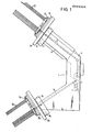
- Fig. 1 is a schematic side view of a device for checking and sorting electronic components, in which a cassette carriage carrier with cassette carriage, cassette and magazine bars is attached to both the entrance and the exit;
- Fig. 2 is an enlarged view of the cassette carriage carrier, the cassette carriage and the cassette;
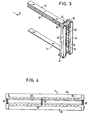
- Fig. 3 is a perspective view of the cassette;
- 4 shows a view IV-IV from FIG. 3.
In Figur 1 ist mit 1 eine Vorrichtung zum Prüfen und Sortieren von IC's bezeichnet. Diese weist ein Eingangsmagazin 2 auf, welches mit einer Vielzahl von parallel verlaufenden und geneigt angeordneten Magazinkanälen versehen ist. Die Magazinkanäle sind senkrecht zur Zeichenebene hintereinander angeordnet. Das Eingangsmagazin 2 ist senkrecht zur Zeichenebene in der von den Magazinkanälen definierten Ebene verfahrbar. Das Eingangsmagazin 2 ist in einer Klimakammer 3 angeordnet, die mit unter Druck stehendem klimatisiertem Gas gefüllt ist. An das Eingangsmagazin schließt sich eine Prüfeinheit 4 an. Der Prüfeinheit 4 werden nacheinander ungeprüfte Bauelemente aus einem in Flucht mit dem Eingang der Prüfeinheit gebrachten Magazinkanal des Eingangsmagazins 2 zugeführt, nachdem sie vorher vereinzelt worden sind.In FIG. 1, 1 denotes a device for checking and sorting ICs. This has an
Die Bauelemente werden dann in der Prüfeinheit 4 geprüft und einer Sortierklasse zugeordnet. Mit dem entsprechenden Sortiersignal wird der Antrieb eines verfahrbaren Shuttles 5 gesteuert, der jeweils ein geprüftes Bauelement aus der Prüfeinheit 4 entnimmt und einem Magazinkanal eines feststehenden Ausgangsmagazins 6 zuführt. Das Ausgangsmagazin 6 hat eine Vielzahl von parallel verlaufenden Magazinkanälen, die in einer senkrecht zur Zeichenebene verlaufenden Ebene liegen. Auch die Kanäle des Ausgangsmagazins 6 sind geneigt angeordnet, so daß die Bauelemente darin durch die Schwerkraft nach unten rutschen. Das gleiche gilt für die Magazinkanäle des Eingangsmagazins 2.The components are then checked in the test unit 4 and assigned to a sorting class. The corresponding sorting signal controls the drive of a movable shuttle 5, which takes a tested component from the test unit 4 and feeds it to a magazine channel of a fixed output magazine 6. The output magazine 6 has a multiplicity of magazines running in parallel channels that lie in a plane perpendicular to the drawing plane. The channels of the output magazine 6 are also inclined, so that the components slide downward due to gravity. The same applies to the magazine channels of the
An die Seitenwände der Vorrichtung 1 sind im Bereich des Eingangsmagazins 2 Trägerbacken 7 angesetzt, zwischen denen sich eine Schwenkwelle 9 erstreckt. Auf dieser Schwenkwelle 9 sitzt ein Kassettenschlitten-Träger 8, welcher seinerseits einen Kassettenschlitten 10 trägt, der in Richtung des Doppelpfeiles auf dem Kassettenschlitten-Träger verschiebbar ist. Der Kassettenschlitten 10 trägt eine auswechselbare Kassette 11, in der wiederum eine Vielzahl von Magazinstangen 12 auswechselbar angeordnet sind.Carrier jaws 7 are attached to the side walls of the
Auch am Ausgang der Vorrichtung 1 sind im Bereich des Ausgangsmagazines 6 seitliche Trägerbacken 7a befestigt, zwischen denen sich eine Schwenkwelle 9a erstreckt. An dieser ist schwenkbar ein Kassettenschlitten-Träger 8a befestigt, der einen Kassettenschlitten 10a aufweist, welcher ebenfalls in-Richtung des Doppelpfeiles verschiebbar ist. Der Kassettenschlitten 10a trägt eine Kassette lla mit Magazinstangen.12a. Die Verhältnisse sind hier völlig analog zu denen des Kassettenschlitten-Trägers mit Kassettenschlitten am Eingang der Vorrichtung. Es soll deshalb nachfolgend nur eine dieser beiden Zusatzvorrichtungen beschrieben werden.Lateral support jaws 7a are also fastened at the outlet of the
Figur 2 zeig. die Trägerwange 7, den Kassettenschlitten-Träger 8, den Kassettenschlitten 10 und die Kassette 11 in vergrößerter Darstellung. Der Kassettenschlitten-Träger 8 ist an der Schwenkwelle 9 mit Gelenklaschen 13 schwenkbar befestigt. Die Gelenklaschen 13 (von denen in Fig. 2 nur eine sichtbar ist) sitzen an einer Grundplatte 14. An der Grundplatte 14 sind zwei Seitenwände 15 befestigt (von denen in Fig. 2 nur eine sichtbar ist). Von den Seitenwänden 15 aus erstrecken sich Führungsschienen 16 nach innen. Auf diesen Führungsschienen 16 läuft der Kassettenschlitten 10 mit an ihm befestigten Führungsrollen 35,36.Figure 2 show. the carrier cheek 7, the cassette carriage carrier 8, the cassette carriage 10 and the
An der Grundplatte 14 des Kassettenschlitten-Trägers 8 sind ferner Halterungen 16,17 für eine Verschlußschiene 17 vorgesehen, deren Bedeutung noch erklärt wird. Weiterhinweist die Grundplatte 14 des Kassettenschlitten-Trägers 8 eine Öffnung 18 auf, durch die sich eine mit einem Handhebel 20 betätigbare Klemmvorrichtung 19 erstreckt. Durch Betätigung des Handhebels 20 kann der Kassetten-Träger-Schlitten 8 an den Trägerwangen 7 festgeklemmt oder gelöst werden, derart, daß der Kassettenschlitten-Träger 8 um die Schwenkwelle 9 von der Vorrichtung 1 wegschwenkbar ist.On the
Die Grundplatte 14 ist mit einer weiteren Öffnung 21 versehen, durch die sich ein Mundstück 23 erstreckt, welches mit der Grundplatte 14 durch einen Halterungsbügel 22 sowie einen Lagerstift 24 verbunden ist. Das Mundstück 23 weist einen Überführungskanal 28 auf, welcher jeweils den Ausgang einer in einer Kassette 11 befindlichen Magazinstange 12 mit einem Magazinkanal des Eingangsmagazins verbindet. In den Überführungskanal 28 ragt ein Förderrad 25, das in Verbindung mit einer Lichtschranke, bestehend aus Lichtgeber 26 und Lichtempfänger 27 eine an sich bekannte Vereinzelungsvorrichtung bildet. Mit dem Förderrad 25 werden die aus einer Magazinstange austretenden Bauelemente 51 vereinzelt und dann einem Magazinkanal des Eingangsmagazins 2 zugeführt.The
Um eine saubere Zentrierung zu gewährleisten, befindet sich an dem dem Eingangsmagazin 2 zugewandten Ende des Mundstückes 23 eine Zunge 29, die in eine Nute 52 an dem verschiebbaren Eingangsmagazin eingreift und gewährleistet, daß der Überführungskanal 28 in jedem Fall mit einem Magazinkanal des Eingangsmagazins 2 in der Höhe korrespondiert.In order to ensure a clean centering, a
Der Kassettenschlitten 10 ist an seiner Unterseite mit einer Zahnstange 33 versehen, die eine Vielzahl von Zahnschlitzen 34 aufweist. Auf der Grundplatte 14 des Kassettenschlitten-Trägers 8 befindet sich ein Exzenterantrieb für den Kassettenschlitten 10. Von diesem ist eine Trägerscheibe mit zwei Exzenterstiften 31,32 sichtbar, von denen jeder in einen Zahnschlitz 34 eingreift. Dieser an sich bekannte Transportmechanismus gewährleistet ein genau definiertes Weiterschalten des Kassettenschlittens 10 und in der dargestellten Stellung der Exzenterstifte 31,32 eine Selbstarretierung gegen ein Verschieben.The cassette carriage 10 is provided on its underside with a
Auf dem Kassettenschlitten 10 sitzen zwei Halterungen 38, 38a für eine Kassette 11. Die Halterung 38 ist mit einem zylinderförmigen Rastelement 40 versehen, das in eine keilförmige Rastausnehmung 39 an der Kassette 11 eingreifen kann. Die Halterung 38a trägt einen zweiarmigen Hebel 43, dessen einer Arm als Handhebel betätigbar ist und dessen anderer Arm ebenfalls ein zylinderförmiges Rastelement 42 aufweist, das in eine entsprechende keilförmige Rastausnehmung 41 der Kassette 11 eingreift. Durch Schwenken des Hebels 43 kann die Kassette gelöst bzw. arret ert werden.Two
In den Figuren 3 und 4 ist eine Kassette genauer dargestellt. Diese besteht aus zwei Seitenteilen 44,45, die durch auswechselbare Distanzstücke 46,47 miteinander verbunden sind. Durch Wahl von Distanzstücken unterschiedlicher Länge kann die Kassette für verschiedene Stangenmagzine 12 verwendet werden. An der Innenseite weisen die Seitenteile 44,45 Verschlußleisten 48,49 auf, die mittels (nicht dargestellten) Federn nach innen in die Verschlußposition gedrückt werden und dadurch die Ausgänge der Magazinstangen 12 teilweise verschließen, so daß aus den Magazinstangen 12 keine Bauelemente austreten können. Ferner weisen die Seitenteile 44,45 an ihrer Innenseite Aufnahmeschlitze 50 für die Magazinstangen 12 auf. Auf diese Weise kann eine Vielzahl von Magazinstangen 12 parallel in die Kassette 11 eingeschoben werden.A cassette is shown in more detail in FIGS. 3 and 4. This consists of two
In Figur 2 ist der Kassettenschlitten 10 in einer Stellung gezeigt, in der noch keine Überführung von Bauelementen aus Magazinstangen 12 zum Eingangsmagazin 2 über das Mundstück 23 erfolgen kann. Dazu ist es erst notwendig, den Kassettenschlitten 10 auf dem Kassettenschlitten-Träger 8 nach unten zu verschieben. Wenn diese Verschiebung nach unten erfolgt,so schiebt sich ein fest am Mundstück 23 befestigtes Öffnungselement 37 zwischen die Verschlußleisten 48,49 der Kassette 11 und drückt diese entgegen der Wirkung der Federn nach außen. Dadurch wird die Ausgangsöffnung der Magazinstangen 12 zum Austritt von Bauelementen freigegeben. Es können jedoch nur Bauelemente 51 aus derjenigen Magazinstange 12 austreten, die mit dem Überführungskanal 28 des Mundstückes 23 fluchtet. Die übrigen noch gefüllten Magazinstangen 12 werden durch die oben beschriebene Verschlußschiene 17 verschlossen,welche in dem Spalt zwischen den beiden Verschlußleisten 48,49 liegt und fest mit dem Kassettenschlitten-Träger 8 verbunden ist. Beim weiterschieben des Kassettenschlittens 10 treten dieIn Figure 2, the cassette carriage 10 is shown in a position in which components from magazine bars 12 to the
Magazinstangen 12 der Kassette 11 aus dem Fluchtbereich des Überführungskanales 28 sowie aus dem Bereich, in dem sie durch die Verschlußschiene 17 verschlossen werden. Sie sind also unverschlossen. Dies ist jedoch insofern ohne Bedeutung, als sie keine Bauelemente mehr enthalten.Magazine bars 12 of the
Wie eingangs beschrieben, ist es auch möglich, mehrere Kassetten 11 auf dem Kassettenschlitten 10 nebeneinander anzuordnen. Die zylinderartigen Rastelemente 40 und 42 dienen dann als Führungen für ein notwendiges seitliches Verschieben der Kassetten, so daß eine nach der anderen in Be- bzw. Entladeposition gebracht wird. Der Verschiebeantrieb ist hier nicht gezeichnet.As described at the beginning, it is also possible to arrange a plurality of
IN den Figuren 2 bis 4 wurde die Zusatzeinrichtung in Verbindung mit dem Eingangsmagazin beschrieben. Die Funktion der Zusatzeinrichtung mit dem Ausgangsmagazin ist analog. Hier muß das Förderrad 25 der Vereinzelungsvorrichtung lediglich in umgekehrter Richtung fördern.FIGS. 2 to 4 describe the additional device in connection with the input magazine. The function of the additional device with the output magazine is analog. Here, the
Claims (11)
Priority Applications (1)
| Application Number | Priority Date | Filing Date | Title |
|---|---|---|---|
| AT86115464T ATE68115T1 (en) | 1985-11-11 | 1986-11-07 | DEVICE FOR TESTING AND SORTING ELECTRONIC COMPONENTS. |
Applications Claiming Priority (2)
| Application Number | Priority Date | Filing Date | Title |
|---|---|---|---|
| DE3539965 | 1985-11-11 | ||
| DE19853539965 DE3539965A1 (en) | 1985-11-11 | 1985-11-11 | DEVICE FOR TESTING AND SORTING ELECTRONIC COMPONENTS |
Publications (3)
| Publication Number | Publication Date |
|---|---|
| EP0222344A2 true EP0222344A2 (en) | 1987-05-20 |
| EP0222344A3 EP0222344A3 (en) | 1988-02-03 |
| EP0222344B1 EP0222344B1 (en) | 1991-10-09 |
Family
ID=6285687
Family Applications (1)
| Application Number | Title | Priority Date | Filing Date |
|---|---|---|---|
| EP86115464A Expired - Lifetime EP0222344B1 (en) | 1985-11-11 | 1986-11-07 | Device for testing and sorting electronic components |
Country Status (4)
| Country | Link |
|---|---|
| US (1) | US4778063A (en) |
| EP (1) | EP0222344B1 (en) |
| AT (1) | ATE68115T1 (en) |
| DE (2) | DE3539965A1 (en) |
Families Citing this family (42)
| Publication number | Priority date | Publication date | Assignee | Title |
|---|---|---|---|---|
| US4941795A (en) * | 1988-11-21 | 1990-07-17 | At&T Bell Laboratories | Component insertion machine apparatus |
| JPH0643204B2 (en) * | 1989-08-26 | 1994-06-08 | 吉田工業株式会社 | Slider supply device |
| US5116185A (en) * | 1990-05-01 | 1992-05-26 | Lsi Logic Corp. | Vibratory tube-to-tube transfer system |
| US5117963A (en) * | 1990-12-12 | 1992-06-02 | Micron Technology, Inc. | System for automated handling of symmetrical supply tubes |
| US5316649A (en) * | 1991-03-05 | 1994-05-31 | The United States Of America As Represented By The United States Department Of Energy | High frequency reference electrode |
| TW287235B (en) * | 1994-06-30 | 1996-10-01 | Zenshin Test Co | |
| DE19827458C2 (en) * | 1998-06-19 | 2001-10-11 | Helmuth Heigl | Separating device for components |
| US7996174B2 (en) | 2007-12-18 | 2011-08-09 | Teradyne, Inc. | Disk drive testing |
| US8549912B2 (en) | 2007-12-18 | 2013-10-08 | Teradyne, Inc. | Disk drive transport, clamping and testing |
| US7945424B2 (en) | 2008-04-17 | 2011-05-17 | Teradyne, Inc. | Disk drive emulator and method of use thereof |
| US8095234B2 (en) | 2008-04-17 | 2012-01-10 | Teradyne, Inc. | Transferring disk drives within disk drive testing systems |
| US8305751B2 (en) | 2008-04-17 | 2012-11-06 | Teradyne, Inc. | Vibration isolation within disk drive testing systems |
| US20090262455A1 (en) | 2008-04-17 | 2009-10-22 | Teradyne, Inc. | Temperature Control Within Disk Drive Testing Systems |
| US8238099B2 (en) | 2008-04-17 | 2012-08-07 | Teradyne, Inc. | Enclosed operating area for disk drive testing systems |
| US7848106B2 (en) | 2008-04-17 | 2010-12-07 | Teradyne, Inc. | Temperature control within disk drive testing systems |
| US8117480B2 (en) | 2008-04-17 | 2012-02-14 | Teradyne, Inc. | Dependent temperature control within disk drive testing systems |
| US8160739B2 (en) | 2008-04-17 | 2012-04-17 | Teradyne, Inc. | Transferring storage devices within storage device testing systems |
| US8102173B2 (en) | 2008-04-17 | 2012-01-24 | Teradyne, Inc. | Thermal control system for test slot of test rack for disk drive testing system with thermoelectric device and a cooling conduit |
| US8041449B2 (en) | 2008-04-17 | 2011-10-18 | Teradyne, Inc. | Bulk feeding disk drives to disk drive testing systems |
| WO2009148942A2 (en) | 2008-06-03 | 2009-12-10 | Teradyne, Inc. | Processing storage devices |
| US8116079B2 (en) | 2009-07-15 | 2012-02-14 | Teradyne, Inc. | Storage device testing system cooling |
| US7920380B2 (en) | 2009-07-15 | 2011-04-05 | Teradyne, Inc. | Test slot cooling system for a storage device testing system |
| US8687356B2 (en) | 2010-02-02 | 2014-04-01 | Teradyne, Inc. | Storage device testing system cooling |
| US8466699B2 (en) | 2009-07-15 | 2013-06-18 | Teradyne, Inc. | Heating storage devices in a testing system |
| US8547123B2 (en) | 2009-07-15 | 2013-10-01 | Teradyne, Inc. | Storage device testing system with a conductive heating assembly |
| US8628239B2 (en) | 2009-07-15 | 2014-01-14 | Teradyne, Inc. | Storage device temperature sensing |
| US7995349B2 (en) | 2009-07-15 | 2011-08-09 | Teradyne, Inc. | Storage device temperature sensing |
| US9779780B2 (en) | 2010-06-17 | 2017-10-03 | Teradyne, Inc. | Damping vibrations within storage device testing systems |
| US8687349B2 (en) | 2010-07-21 | 2014-04-01 | Teradyne, Inc. | Bulk transfer of storage devices using manual loading |
| US9001456B2 (en) | 2010-08-31 | 2015-04-07 | Teradyne, Inc. | Engaging test slots |
| US9459312B2 (en) | 2013-04-10 | 2016-10-04 | Teradyne, Inc. | Electronic assembly test system |
| US11226390B2 (en) | 2017-08-28 | 2022-01-18 | Teradyne, Inc. | Calibration process for an automated test system |
| US10845410B2 (en) | 2017-08-28 | 2020-11-24 | Teradyne, Inc. | Automated test system having orthogonal robots |
| US10725091B2 (en) | 2017-08-28 | 2020-07-28 | Teradyne, Inc. | Automated test system having multiple stages |
| US10948534B2 (en) | 2017-08-28 | 2021-03-16 | Teradyne, Inc. | Automated test system employing robotics |
| US10983145B2 (en) | 2018-04-24 | 2021-04-20 | Teradyne, Inc. | System for testing devices inside of carriers |
| US10775408B2 (en) | 2018-08-20 | 2020-09-15 | Teradyne, Inc. | System for testing devices inside of carriers |
| US11754596B2 (en) | 2020-10-22 | 2023-09-12 | Teradyne, Inc. | Test site configuration in an automated test system |
| US11953519B2 (en) | 2020-10-22 | 2024-04-09 | Teradyne, Inc. | Modular automated test system |
| US11899042B2 (en) | 2020-10-22 | 2024-02-13 | Teradyne, Inc. | Automated test system |
| US11754622B2 (en) | 2020-10-22 | 2023-09-12 | Teradyne, Inc. | Thermal control system for an automated test system |
| US11867749B2 (en) | 2020-10-22 | 2024-01-09 | Teradyne, Inc. | Vision system for an automated test system |
Citations (4)
| Publication number | Priority date | Publication date | Assignee | Title |
|---|---|---|---|---|
| US4049123A (en) * | 1976-06-01 | 1977-09-20 | Western Electric Company, Inc. | Methods of and apparatus for sorting articles in accordance with their resistivity and thickness |
| US4500246A (en) * | 1983-03-01 | 1985-02-19 | Universal Instruments Corporation | Indexed feed of electronic component supply tubes |
| EP0146729A1 (en) * | 1983-11-07 | 1985-07-03 | Hans-Heinrich Willberg | Device for transferring components, in particular integrated chips, from an input tray to an output tray |
| EP0192206A2 (en) * | 1985-02-19 | 1986-08-27 | MICROHANDLING Handhabungsgeräte GmbH | Apparatus for storing elongate units of packages comprising for instance parts of integrated circuits |
Family Cites Families (15)
| Publication number | Priority date | Publication date | Assignee | Title |
|---|---|---|---|---|
| DE225882C (en) * | ||||
| US3308977A (en) * | 1965-10-04 | 1967-03-14 | Ibm | Automatic tray handler |
| US3716786A (en) * | 1970-10-02 | 1973-02-13 | Cogar Corp | Module tester and sorter for use in a module test system |
| US3727757A (en) * | 1972-06-12 | 1973-04-17 | C Boissicat | Dip handling apparatus |
| US3896935A (en) * | 1973-11-26 | 1975-07-29 | Ramsey Eng Co | Integrated circuit handler |
| US4124132A (en) * | 1977-05-18 | 1978-11-07 | Sola Basic Industries, Inc. | Magazine apparatus for semiconductor processing device |
| US4234418A (en) * | 1978-06-23 | 1980-11-18 | Contrel Corporation | Dip-handling apparatus |
| DE2855913C2 (en) * | 1978-12-23 | 1983-05-19 | Licentia Patent-Verwaltungs-Gmbh, 6000 Frankfurt | Device for sorting components |
| JPS56168566A (en) * | 1980-05-30 | 1981-12-24 | Toshiba Corp | Ic autohandler |
| JPS5896258A (en) * | 1981-12-03 | 1983-06-08 | Fujitsu Ltd | Docking mechanism for parts case in autohandler for electronic parts tester |
| US4506213A (en) * | 1983-07-18 | 1985-03-19 | Sym-Tek Systems, Inc. | Electronic device handler |
| DE3340185A1 (en) * | 1983-11-07 | 1985-05-15 | Multitest Elektronische Systeme GmbH, 8200 Rosenheim | DEVICE FOR RECORDING COMPONENTS, IN PARTICULAR OF INTEGRATED CHIPS, IN AN INPUT AND / OR OUTPUT MAGAZINE OF A COMPONENT TESTING MACHINE |
| US4588092A (en) * | 1983-11-15 | 1986-05-13 | Automated Electronic Technology, Inc. | Integrated circuit handling and contact system |
| US4618305A (en) * | 1983-11-23 | 1986-10-21 | Daymarc Corporation | Automatic feed apparatus and process for integrated circuits stored in tubes |
| DE3584319D1 (en) * | 1984-06-29 | 1991-11-14 | Advantest Corp | IC TEST DEVICE. |
-
1985
- 1985-11-11 DE DE19853539965 patent/DE3539965A1/en not_active Withdrawn
-
1986
- 1986-10-22 US US06/921,434 patent/US4778063A/en not_active Expired - Fee Related
- 1986-11-07 EP EP86115464A patent/EP0222344B1/en not_active Expired - Lifetime
- 1986-11-07 AT AT86115464T patent/ATE68115T1/en not_active IP Right Cessation
- 1986-11-07 DE DE8686115464T patent/DE3681877D1/en not_active Expired - Lifetime
Patent Citations (4)
| Publication number | Priority date | Publication date | Assignee | Title |
|---|---|---|---|---|
| US4049123A (en) * | 1976-06-01 | 1977-09-20 | Western Electric Company, Inc. | Methods of and apparatus for sorting articles in accordance with their resistivity and thickness |
| US4500246A (en) * | 1983-03-01 | 1985-02-19 | Universal Instruments Corporation | Indexed feed of electronic component supply tubes |
| EP0146729A1 (en) * | 1983-11-07 | 1985-07-03 | Hans-Heinrich Willberg | Device for transferring components, in particular integrated chips, from an input tray to an output tray |
| EP0192206A2 (en) * | 1985-02-19 | 1986-08-27 | MICROHANDLING Handhabungsgeräte GmbH | Apparatus for storing elongate units of packages comprising for instance parts of integrated circuits |
Non-Patent Citations (1)
| Title |
|---|
| Prospekt "TESEC Semiconductor Equipment", 1982/83, Handler 7703-IH, TESEC CORPORATION JAPAN * |
Also Published As
| Publication number | Publication date |
|---|---|
| EP0222344A3 (en) | 1988-02-03 |
| US4778063A (en) | 1988-10-18 |
| DE3539965A1 (en) | 1987-05-14 |
| EP0222344B1 (en) | 1991-10-09 |
| ATE68115T1 (en) | 1991-10-15 |
| DE3681877D1 (en) | 1991-11-14 |
Similar Documents
| Publication | Publication Date | Title |
|---|---|---|
| EP0222344B1 (en) | Device for testing and sorting electronic components | |
| EP0683101A2 (en) | Device for automatically filling the main magazine of a labelling machine and magazine for use in such a device | |
| DE4314613A1 (en) | Packaging machine | |
| EP0204291B1 (en) | Device for testing and sorting electronic components, in particular integrated chips | |
| DE3644423C2 (en) | ||
| DE3221620A1 (en) | DEVICE FOR ATTACHING COMPONENTS | |
| EP0253015A1 (en) | Transport system for a testing device for electronic components | |
| DE3539957A1 (en) | Hopper loading and unloading device for fitted and unfitted boards to supply a fitting machine | |
| DE10012665A1 (en) | Tool-changing device for machine tool; has tool magazine for tool to be changed and tool holder device in transport device to rotate tool between ready position and position parallel to spindle | |
| EP0734975A1 (en) | Shelf storage with movable racks | |
| DE2849751C2 (en) | Device for separating cut-to-length wires forming a loose bundle, in particular for feeding wire to a processing machine | |
| DE3715671A1 (en) | Device for testing and sorting electronic components, particularly chips with integrated circuits (ICs) | |
| DE2903741C2 (en) | Production system for processing the two end areas of profile material sections of different lengths, in particular brake line pipes for motor vehicles | |
| DE2807573C2 (en) | Device for inserting individual pin-shaped parts into holding bodies | |
| DE3531120C2 (en) | Device for checking and sorting electronic components, in particular integrated chips | |
| EP0807480A1 (en) | Device for transporting single rods between machine tools | |
| DE3600700C2 (en) | ||
| EP0143990B1 (en) | Device for testing and sorting of electronic components, especially of integrated circuits | |
| EP0223189A1 (en) | Apparatus for testing and sorting electronic modules | |
| DE19822998A1 (en) | Appliance for inserting stacked envelopes into crate | |
| DE2523678C3 (en) | Self-seller | |
| AT404439B (en) | DEVICE FOR DISTRIBUTING ROD-SHAPED ELEMENTS | |
| DE1703224C3 (en) | Intermittent multi-daylight press for the production of chipboard or the like | |
| DE1511782A1 (en) | Control device for cigarette blocks in packaging lanes | |
| DE3437847A1 (en) | Minting press for coins and medals or the like |
Legal Events
| Date | Code | Title | Description |
|---|---|---|---|
| PUAI | Public reference made under article 153(3) epc to a published international application that has entered the european phase |
Free format text: ORIGINAL CODE: 0009012 |
|
| AK | Designated contracting states |
Kind code of ref document: A2 Designated state(s): AT BE CH DE FR GB IT LI LU NL SE |
|
| PUAL | Search report despatched |
Free format text: ORIGINAL CODE: 0009013 |
|
| AK | Designated contracting states |
Kind code of ref document: A3 Designated state(s): AT BE CH DE FR GB IT LI LU NL SE |
|
| 17P | Request for examination filed |
Effective date: 19880720 |
|
| 17Q | First examination report despatched |
Effective date: 19880927 |
|
| GRAA | (expected) grant |
Free format text: ORIGINAL CODE: 0009210 |
|
| AK | Designated contracting states |
Kind code of ref document: B1 Designated state(s): AT BE CH DE FR GB IT LI LU NL SE |
|
| PG25 | Lapsed in a contracting state [announced via postgrant information from national office to epo] |
Ref country code: IT Free format text: LAPSE BECAUSE OF FAILURE TO SUBMIT A TRANSLATION OF THE DESCRIPTION OR TO PAY THE FEE WITHIN THE PRESCRIBED TIME-LIMIT;WARNING: LAPSES OF ITALIAN PATENTS WITH EFFECTIVE DATE BEFORE 2007 MAY HAVE OCCURRED AT ANY TIME BEFORE 2007. THE CORRECT EFFECTIVE DATE MAY BE DIFFERENT FROM THE ONE RECORDED. Effective date: 19911009 Ref country code: NL Effective date: 19911009 Ref country code: GB Effective date: 19911009 Ref country code: BE Effective date: 19911009 Ref country code: SE Effective date: 19911009 |
|
| REF | Corresponds to: |
Ref document number: 68115 Country of ref document: AT Date of ref document: 19911015 Kind code of ref document: T |
|
| PG25 | Lapsed in a contracting state [announced via postgrant information from national office to epo] |
Ref country code: AT Effective date: 19911107 |
|
| REF | Corresponds to: |
Ref document number: 3681877 Country of ref document: DE Date of ref document: 19911114 |
|
| PG25 | Lapsed in a contracting state [announced via postgrant information from national office to epo] |
Ref country code: CH Effective date: 19911130 Ref country code: LU Free format text: LAPSE BECAUSE OF NON-PAYMENT OF DUE FEES Effective date: 19911130 Ref country code: LI Effective date: 19911130 |
|
| EN | Fr: translation not filed | ||
| PG25 | Lapsed in a contracting state [announced via postgrant information from national office to epo] |
Ref country code: FR Effective date: 19920228 |
|
| NLV1 | Nl: lapsed or annulled due to failure to fulfill the requirements of art. 29p and 29m of the patents act | ||
| GBV | Gb: ep patent (uk) treated as always having been void in accordance with gb section 77(7)/1977 [no translation filed] | ||
| REG | Reference to a national code |
Ref country code: CH Ref legal event code: PL |
|
| PLBE | No opposition filed within time limit |
Free format text: ORIGINAL CODE: 0009261 |
|
| STAA | Information on the status of an ep patent application or granted ep patent |
Free format text: STATUS: NO OPPOSITION FILED WITHIN TIME LIMIT |
|
| 26N | No opposition filed | ||
| REG | Reference to a national code |
Ref country code: FR Ref legal event code: ST |
|
| PGFP | Annual fee paid to national office [announced via postgrant information from national office to epo] |
Ref country code: DE Payment date: 19930129 Year of fee payment: 7 |
|
| PG25 | Lapsed in a contracting state [announced via postgrant information from national office to epo] |
Ref country code: DE Effective date: 19940802 |