EP0222682A1 - Signal transmission system for a comparison protection device - Google Patents
Signal transmission system for a comparison protection device Download PDFInfo
- Publication number
- EP0222682A1 EP0222682A1 EP86730150A EP86730150A EP0222682A1 EP 0222682 A1 EP0222682 A1 EP 0222682A1 EP 86730150 A EP86730150 A EP 86730150A EP 86730150 A EP86730150 A EP 86730150A EP 0222682 A1 EP0222682 A1 EP 0222682A1
- Authority
- EP
- European Patent Office
- Prior art keywords
- signal
- frequency signal
- input
- output
- keying
- Prior art date
- Legal status (The legal status is an assumption and is not a legal conclusion. Google has not performed a legal analysis and makes no representation as to the accuracy of the status listed.)
- Granted
Links
Images


Classifications
-
- H—ELECTRICITY
- H02—GENERATION; CONVERSION OR DISTRIBUTION OF ELECTRIC POWER
- H02H—EMERGENCY PROTECTIVE CIRCUIT ARRANGEMENTS
- H02H7/00—Emergency protective circuit arrangements specially adapted for specific types of electric machines or apparatus or for sectionalised protection of cable or line systems, and effecting automatic switching in the event of an undesired change from normal working conditions
- H02H7/26—Sectionalised protection of cable or line systems, e.g. for disconnecting a section on which a short-circuit, earth fault, or arc discharge has occured
- H02H7/261—Sectionalised protection of cable or line systems, e.g. for disconnecting a section on which a short-circuit, earth fault, or arc discharge has occured involving signal transmission between at least two stations
-
- H—ELECTRICITY
- H02—GENERATION; CONVERSION OR DISTRIBUTION OF ELECTRIC POWER
- H02H—EMERGENCY PROTECTIVE CIRCUIT ARRANGEMENTS
- H02H1/00—Details of emergency protective circuit arrangements
- H02H1/0061—Details of emergency protective circuit arrangements concerning transmission of signals
Definitions
- the invention relates to a signal transmission arrangement for a comparative protection device, in which measured values are detected in two monitoring stations at two ends of a protective section of an energy transmission system to be monitored, and in each monitoring station a switch-off signal for a switch at the respective end depending on the measured variables recorded in both monitoring stations of the protective section is generated, with a signal line connecting the two monitoring stations for transmitting the measured variables or a comparison variable formed from them, and with two transmitting / receiving devices, each having a frequency signal generator and a frequency signal receiver with an error message output and a transmitter, the frequency signal generator being one of the the two transmitting / receiving devices is connected on the output side via the associated transmitter to one end of the signal line and the frequency signal l Receiver of the other transceiver is connected on the input side via the corresponding transmitter to the other end of the signal line.
- Such a signal transmission arrangement known from Siemens catalog R1 "Electronic Protection Devices", 1979 and shown there on page 6/13 in Figures 6/16 and 6/17 is part of a comparative protection device designed as a line differential protection device, in which one ends at two ends monitoring Energy transmission line in a monitoring station, the phase currents are detected on the line; a differential current is derived from the phase currents detected at both ends of the energy transmission line and flows on a two-wire signal line between the two monitoring stations.
- the differential current is used in each monitoring station to form a switch-off signal in the event of a line fault for a switch which is arranged in the course of the energy transmission line at its end assigned to the monitoring station in question and is controlled by the latter.
- a transmitter / receiver device with a frequency signal generator, a frequency signal receiver and a transmitter is connected to both ends of the signal line in each monitoring station. While in one of the two transmitting / receiving devices the frequency signal generator is connected via the transmitter to the corresponding end of the signal line, in the other transmitting / receiving device the frequency signal receiver arranged in it is connected to the associated transmitter at the other end of the signal line and monitors it Presence of the frequency signal output by the frequency signal generator at one end of the signal line.
- the invention is based on the object of specifying a signal transmission arrangement for a comparison protection device with an error-monitored signal line between two monitoring stations, which enables mutual excitation of both monitoring stations on the basis of a carry signal generated in one of the two monitoring stations or supplied externally to them, without the need for an additional signal transmission path is.
- the output of the frequency signal generator is connected to the input of the frequency signal receiver in that each frequency signal generator has a control input that can be activated by a driving signal, that the frequency signal generator is one Transmitter / receiver for emitting a first frequency signal clocked with a predetermined key and key pause time when the control input is deactivated is designed such that the output of the frequency signal generator in the other transmitter / receiver is switched off when the control input is deactivated, that both frequency signal generators are acted upon by the driving signal on the control input side can be activated in each case for the output-side delivery of a second clocked frequency signal with a further predetermined key and key pause time that each frequency signal
- Each receiver contains a signal evaluation device connected to its input, which on the output side has a switch-off signal for that one Monitoring station assigned switches depending on the fact that at least once at the input of the frequency signal receiver, a frequency signal with a signal duration at least approximately
- the main advantage of the signal transmission arrangement according to the invention is that, in addition to the transmission of the measured variables or the comparison variable between the monitoring stations and the function of monitoring the signal line, it also enables the transmission of driving signals between the two monitoring stations on the signal line.
- the transmitters / receivers are galvanically isolated from the signal line and the monitoring stations connected to it by the transmitters; for signal separation, band filters matched to the frequency of the frequency signals can be arranged on the input side in the transmitting / receiving devices.
- the distinction between the first frequency signal for monitoring the signal line and the second frequency signal for transmitting a driving signal is made in the signal evaluation devices of the frequency signal receivers of the two transmitting / receiving devices by checking the respectively received signals for their keying and keying pause times.
- the first frequency signal is fed into the signal line by the one transmitting / receiving device with the predetermined keying and keying pause times. If the signal line is free of errors, the first frequency signal is received in the frequency signal receiver of the other transmitting / receiving device and there causes a permanent resetting of the time elapsing stage, the elapsing time of which is selected to be greater than the keying interval of the first frequency signal. In the event of a signal line fault, the first frequency signal cannot be received, so that the time-out stage expires and emits an error signal.
- the relevant frequency signal generator switches the second frequency signal to the signal line with the further keying and keying pause times; the evaluation of the second frequency signal is advantageously prevented in the signal evaluation device of the own frequency signal receiver in that each signal evaluation device has a deactivation input to which the carry signal can be applied.
- the transmission of the driving signal by the one transmitting / receiving device is recognized when the frequency signal received in each case has at least approximately the additional keying and keying pause time specified for the transmission of keying signals.
- the function of monitoring the signal line is also retained when transmitting carry signals on the signal line, provided that the further scanning pause time of the second frequency signal is less than the expiry time of the time lapse stages in the frequency signal receivers of the two transmitting / receiving devices.
- the keying time and further keying time are each of the same predetermined duration and the keying pause time is many times larger than the keying time and is several times larger than the further keying pause time.
- This has the advantageous effect that even in the event that the one transmitting / receiving device transmits the first frequency signal for signal line monitoring and the opposite transmitting / receiving device transmits the second frequency signal for transmitting a carry signal, during each pause period of the first frequency signal the second frequency signal appears to the signal line with a plurality of further sampling times and sampling pause times and can thus be identified by the respective signal evaluation device, at least in its sampling pause times, despite the superposition with the first frequency signal.
- each frequency signal generator contains a sine generator which is connected to the output of the frequency signal generator via a controllable analog switching device, that the analog switching device is assigned a clock signal generator controlling this via its control output, that the sine generator has a rectangular pulse generator and this
- a pulse counting device for emitting counting pulses is arranged downstream that the pulse counting device is connected on the output side to the clock signal generator, which derives from the counting pulses a first clock signal with the predetermined keying and keying pause time and a second clock signal with the further keying and keying pause time and that the clock signal generator has a switching input forming the control input of the frequency signal generator, when the latter is acted upon by the driving signal, the clock signal generator from the delivery of the first clock signal gnals is switchable at its control output to the delivery of the second clock signal.
- the preferably tone-frequency AC voltage at the output of the sine generator is switched through to the signal line via the controllable analog switching device in accordance with its activation with the one key and key pause time or the further key and key pause time.
- the keying and keying pause time or further keying and keying pause time is derived from the frequency of the sinusoidal alternating voltage with the aid of the rectangular pulse shaper and the downstream pulse counting device, so that the first or second frequency signal emitted by the transceiver onto the signal line in each sampling time or additional sampling time each has a predetermined number of alternating voltage periods.
- Each clock signal generator advantageously has a function input for suppressing the generation of the first clock signal.
- the two transmitters / receivers can be mutually adjusted via the function inputs in such a way that one of the two transmitters / receivers feeds the first frequency signal for monitoring the signal line into them and in the other transmitter / receiver device the generation of the first frequency signal the function input is switched off.
- each signal evaluation device for detecting the signal duration of the respectively received frequency signal contains a timer stage which is arranged downstream of the input of the associated frequency signal receiver with its start input and at least approximately with one of the further sampling times corresponding output time emits an output signal that a pulse counter with its counting input is arranged downstream of the input of the frequency signal receiver in question, that the timer stage and the pulse counter
- An evaluation logic is arranged downstream, which monitors the pulse counter for reaching the minimum counter reading during the expiry time in order to generate the switch-off signal and suppresses the generation of the switch-off signal as soon as the pulse counter reaches a predetermined maximum counter reading.
- the timing sequence is started with the first oscillation of the frequency signal.
- the pulse counter counts the vibrations of the frequency signal and the downstream evaluation logic blocks the generation of the switch-off signal if a number of vibrations corresponding to the minimum count has not been received within the expiry time or if the number of received vibrations reaches the maximum count.
- each signal evaluation device contains a clock-controlled pulse pause counter, whose reset input is arranged downstream of the input of the assigned frequency signal receiver;
- the pulse pause counter is followed by the evaluation logic, which monitors the pulse pause counter for generating a switch-off signal for reaching a further minimum counter reading and suppresses the generation of the switch-off signal as soon as a predetermined further maximum counter reading is reached.
- the timer stage and are located in each transmitting / receiving device the pulse pause counter is connected to the pulse counter of the frequency signal generator via clock inputs.
- the expiry time of the time expiry stage and the time base for the pulse pause counter are derived from the frequency of the sine wave generator, so that the received frequency signals are monitored very precisely for their keying and keying pause times.
- the comparative protection device has two monitoring stations 1 and 2, which are each arranged at different ends 3 and 4 of a protective section 5 of a power supply system to be monitored - here a three-phase power transmission line. With the help of transducers 6 and 7, the phase voltages and / or phase currents of the energy transmission line which occur there are detected at each end 3 and 4 of the protective section 5 and fed as measurement variables to the respective monitoring stations 1 and 2 at measuring inputs 8 and 9, respectively.
- Each of the two monitoring stations 1 and 2 each has a control output 10 or 11 for emitting a switch-off signal to an assigned controllable switch 12 or 13 which is arranged at the respective end 3 or 4 of the protective section 5 in the course of the energy transmission line.
- the switch-off signal for the respective isolating switch 12 or 13 is generated in the assigned monitoring station 1 or 2 in each case as a function of the measured variables detected at both ends 3 and 4 of the protective section 5.
- the two monitoring stations 1 and 2 are connected to one another via a two-wire signal line 14, on which the measured variables or a comparison variable formed from them are transmitted between the two monitoring stations 1 and 2, so that in each monitoring station 1 and 2 there is an evaluation of the two End 3 and 4 measured variables is enabled.
- a signal transmission arrangement is provided with two transceivers 15 and 16, which are assigned to the respective monitoring stations 1 and 2 and at the ends of the Signal line 14 are connected.
- Each transmitting / receiving device 15 or 16 is connected via a control input 17 or 18 to a signal output 19 or 20 of the relevant monitoring station 1 or 2; the signal outputs 19 and 20 each serve to deliver a in the relevant monitoring station, for. B. 1 generated driving signal, which is transmitted via the signal line 14 to the opposite monitoring station 2 and is used there to excite the monitoring station 2 in the sense of delivering a shutdown signal to the associated disconnector 13.
- each transmitting / receiving device 15 and 16 each have an output 21 or 22 for emitting a switch-off signal to a corresponding input 23 or 24 of the assigned monitoring station 1 or 2.
- each transmitting / receiving device 15 and 16 each has an error reporting output 25 or 26, on which indicator elements, not shown here, such as, for. B. signal lamps or signal relays can be connected.
- To monitor the signal line 14 is in one direction from a transmitting / receiving device, for. B. 15, to the opposite transmitting / receiving device 16 via the signal line 14 transmit a first frequency signal consisting of a sinusoidal AC voltage with a frequency of 2 kHz, which is clocked with a keying time of 8 ms and a subsequent key pause time of 72 ms .
- a fault in the signal line 14 is indicated with a delay of approximately 3 seconds on the error message output 26 of the transceiver 16.
- the carry signal can be sent and received by both transceivers 1 and 2.
- the transmission of a driving signal takes place in the form of a second frequency signal, in preference to the transmission of the first frequency signal used for signal line monitoring; the second frequency signal also consists of a sinusoidal AC voltage with a frequency of 2 kHz, which, however, is clocked with a further pulse time of 8 ms and a further pulse pause time of likewise 8 ms.
- the second frequency signal is evaluated on the receiving side by counting the respectively received vibrations, an error-free reception of a driving signal being recognized when the received one Frequency signal twice in succession has a signal duration which at least approximately corresponds to the further keying time and subsequently has a signal pause which at least approximately corresponds to the further keying pause time.
- Fig. 2 shows the basic structure of one of the two identical transmitters / receivers 15 and 16. To simplify each other, connected inputs and outputs are indicated the same way.
- Each transmitter / receiver device contains a frequency signal generator 30 with an output 31 and a frequency signal receiver 32 with an input 33.
- the output 31 of the frequency signal generator 30 and the input 33 of the frequency signal receiver 32 are connected to one another and connected to a transmission side of a transmitter 34 which is located on the other side of the transmission on the two-wire signal line 14.
- the frequency signal generator 30 contains a sine / square wave generator 35 which outputs a sinusoidal AC voltage of 2 kHz at an output SI and outputs square wave signals derived from the sinusoidal AC voltage at further outputs B0, B1, B2, B4, D0, D1, D2 and D4 .
- a controllable analog switch 36 which switches through the AC voltage supplied to its input SI as a function of a signal at its control input St to the transformer 34.
- the control input St is connected to a correspondingly designated control output of a clock signal generator 37.
- the switching input M is connected directly to a control input 17 of the frequency signal generator 30 and from the assigned one Monitoring station 1 (see FIG. 1) can be acted upon with the carry signal.
- the clock signal generator 37 also has a functional input A, via which the delivery of the first clock signal can be switched off.
- the clock generator 37 is activated in the transmitting / receiving device 15 for emitting the first clock signal, while in the opposite transmitting / receiving device 16 the clock signal generator 37 in question is switched off with respect to the emitting of the first clock signal.
- the clock signal generator 37 is connected at clock inputs B0, D0 and D4 to the correspondingly designated outputs of the sine / square wave generator 35.
- the clock signal generator 37 has an additional input EB, via which suppression of the delivery of the first clock signal is possible.
- the first frequency signal with 16 successive frequency signal oscillations in 8 ms and a subsequent signal pause of 71 ms transmitted to monitor the signal line 14 from the transmitting / receiving device 15 via the signal line 14 to the transmitting / receiving device 16
- the respective transceiver 15 or 16 emits the second frequency signal with 8 ms each and a subsequent signal pause of 8 ms as well.
- controllable analog switching device 36 consisting of a controllable analog switch 45 and a downstream amplifier 46.
- FIG. 5 shows the structure of the clock signal generator 37, which contains a binary counter 47, an AND gate 48 and an OR gate 49. These are arranged in such a way that the changeover input M, the function input A, the inputs D0 and D4 are inputs of the AND gate 48; the additional input EB forms an inverting input of the AND gate 48.
- the input B0 of the clock signal generator 37 is formed by the clock input 50 of the binary counter 47, which also has a reset input R connected to the switchover input M.
- the OR gate 49 is arranged after the binary counter 47 and the AND gate 48 in such a way that an input 51 of the OR gate 49 with the output B4 of the binary counter 47 is connected and a further input 52 of the OR gate 49 is connected to the output of the AND gate 48.
- the output of the OR gate 49 forms the control output St of the clock signal generator 37. If the switching input M is deactivated by applying a signal level "1", the clock signal generator 37 generates a clock signal at its control output St with a keying and keying pause time of 8 ms or 72 ms; this first clock signal can be suppressed by applying a signal level "0" to the functional input A. By applying a driving signal in the form of a signal level "0" to the switching input M, this is activated, and the second clock signal is output at the control output St with a keying and keying pause time of 8 ms each. The output of the first clock signal can be blocked with a signal level "1" at the additional input EB.
- the frequency signal receiver 32 contains a receiving stage 53 which is connected to the input 33 of the frequency signal receiver 32. As shown in FIG. 6, this receiving stage 53 consists of a bandpass filter 54 located at the input 33, an amplifier stage 55 arranged downstream of this and a subsequent rectangular pulse shaping stage 56 which forms the output E of the receiving stage 53 on the output side.
- a signal evaluation device 57 (FIG. 2) is arranged at the output E of the reception stage 53 and essentially consists of a timer stage 58, a pulse counter 59, a pulse pause counter 60 and a downstream evaluation logic 61.
- the timer stage 58 is shown in more detail in FIG. 7 and contains a flip-flop 62 with a downstream one Decimal counter 63.
- the set input S of the flip-flop 62 forms the start input E of the timer stage 58 and is connected to the output E of the reception stage 53.
- the reset input R of the flip-flop 62 and the reset input of the downstream decimal counter 63 are connected to one another and connected to a correspondingly designated reset output of the pulse pause counter 60.
- the decimal counter 63 has an AND gate upstream of its clock input, which is connected on the input side to the output 64 of the flip-flop 64 and is connected to the output B0 of the sine / square wave generator 35.
- the output D4 of the decimal counter 63 forms the output T of the timer stage 58.
- the timer stage 58 is started via its start input E with the first oscillation of a frequency signal occurring at the input 33 of the frequency signal receiver 32 and generates a signal state "1" at its output T after 8 ms These 8 ms form the expiry time of the timer stage 58 and thus correspond at least approximately to the further duty cycle of the second frequency signal for the transmission of a driving signal.
- the pulse counter 59 contains a decimal counter 65 and a downstream AND gate 66.
- the decimal counter 65 like the timer stage 58 already described above, is connected via a reset input R to the correspondingly designated reset output of the pulse pause counter 60.
- the decimal counter 65 has an upstream AND gate which is connected on the input side to the output E of the receiving stage 53 via a connection 67 which forms the counter input E of the pulse counter 59.
- Another inverting input 68 of the AND gate preceding the clock input of the decimal counter 65 is connected to the output 69 of the AND gate 66.
- the decimal counter 65 points a first output "14" which indicates a signal when the counter reading is greater than or equal to 14.
- a second output "19" of the decimal counter 65 indicates when the counter reading reaches the value 19.
- This second output "19” is connected to an input 70 of the AND gate 66, which is connected on the output side to an output "19” of the pulse counter S9.
- Another input 71 of the AND gate 66 forms an input UB of the pulse counter 59, which serves to block the overflow function and the output "19" of the pulse counter 59.
- FIG. 9 shows the structure of the pulse pause counter 60, which has a decimal counter 72 and two AND gates 73 and 74 arranged after it.
- the decimal counter 72 has a clock input with an upstream AND gate, which is connected via an input connection 75 to the output B0 of the sine / square wave generator 35.
- the decimal counter 72 also has a reset input R, which is connected to the output E of the receiving stage 53 and to those designated accordingly.
- the output D1 of the decimal counter 72 is connected to the reset inputs R of the timer stage 58 and the pulse counter 59.
- the timer stage 58 and the pulse counter 59 are reset via this output R whenever the signal pause between two received frequency signal oscillations is greater than 1 to 2 ms.
- the outputs D0, D1 and D2 of the decimal counter 72 are followed by the AND gate 73, which emits a signal at its output "7" when no signal appears at the input E of the pulse pause counter 60 for a time of 6 to 7 ms.
- the outputs D0 and D4 of the decimal counter 72 are followed by the further AND gate 74, which emits a signal at its output "9” when there is no signal at the input E of the pulse pause counter 60 for a time of 8 to 9 ms.
- the output "9” has an inverting input 76 of the AND gate upstream of the clock input of the decimal counter 72 is connected and blocks the decimal counter 72 as soon as a signal appears at the output "9".
- a counter 77 is assigned to the timer stage 58, the pulse counter 59 and the pulse pause counter 60, which is shown in more detail in FIG. 10.
- the counter 77 contains a flip-flop 78, a downstream AND gate 79 and a downstream decimal counter 80.
- the counter 77 releases the take-away decision within a predetermined time.
- the inputs and outputs of the counter 77 have the following functions:
- the input E is started with the first received frequency signal oscillation at the input 33 of the frequency signal receiver 32.
- a signal "1" at the input R stops the counter 77 and resets the outputs to "0".
- a signal state "0" at input M is present when the own monitoring station, for. B. 1, a carry signal is sent.
- the structure of the timer stage 58, the pulse counter 59, The evaluation logic 61 arranged downstream of the pulse pause counter 60 and the counter device 77 is shown in FIG. 11.
- the evaluation logic 61 contains two AND gates 81 and 82, which is followed by an OR gate 83.
- the AND gate 81 is connected on the input side to the output T of the timer stage 58, the first output "14" of the pulse counter 59 and the output F of the counter 77; the AND gate 82 is connected on the input side to the output "7" of the pulse pause counter 60 and the output F of the counter 77.
- the OR gate 83 controls a subordinate decimal counter 84 via its clock input 85; the decimal counter 84 is connected via its counter output D0 to an inverting input of the AND gate 81 and a non-inverting input of the AND gate 82.
- the evaluation logic 61 also contains a further OR gate 86, which is connected on the input side to the outputs "19" and "9" of the pulse or pulse pause counter 59 or 60 and is connected via an inverting input to a reactivation input DE which can be acted upon by the driving signal is.
- the OR gate 86 is connected on the output side to a reset input R of the decimal counter 84 and further to the reset input R of the counter 77.
- the output D2 of the decimal counter 84 forms the output of the evaluation logic 11.
- the evaluation logic 61 combines the output signals of the timer stage 58, the pulse counter 59, the pulse pause counter 60 and the counter 77 in such a way that the output R assumes the state "1" when inputs "9” or “19” have status "1” applied to them or if input M has status "0". This is the case if more than 9 frequency signal oscillations follow one another in the case of a received frequency signal or if the signal pause reaches or exceeds 19 ms. In this case, no carry signal or second frequency signal has been received and the signal state at output D2 of evaluation logic 61 is "0".
- an output signal "1" is emitted at the output D2 of the evaluation logic 61 if the limit values for the pulse times and the respective two times within a time of a maximum of 48 to 52 ms from the start of the first frequency signal oscillation of a frequency signal received at the input 33 of the frequency signal receiver 32 Touch pause times with 14 to a maximum of 19 consecutive oscillation periods in a time of 7 to 8 ms and a subsequent touch pause time of at least 6 to a maximum of 9 ms in the order of touch time - touch pause time - touch time - touch pause time.
- a downstream delay stage 87 is controlled, which is shown in more detail in FIG. 12.
- the delay stage 87 contains an AND gate 88 connected on the input side to the output D2 of the evaluation logic 61 and the output “8” of the counter 77, a decimal counter 89 and a flip-flop 90.
- the input D4 of the delay stage 87 serves to control the decimal counter 80 and is connected to the corresponding output of the sine-wave generator 35.
- the switch-off signal at the output 21 is reset by the decimal counter 80 with a delay of approximately 560 to 640 ms after the input signal at the input D2 falls back to "0".
- a switch-off signal for the assigned monitoring stage, for. B. 1 when a frequency signal in the frequency signal receiver has been received, which corresponds to the carrier signal emitted by the respective remote station in the form of the second frequency signal.
- a timing sequence stage 91 is provided for monitoring the signal line 14 and, as shown in FIG. 13, consists of a decimal counter. This decimal counter is connected with its counting input D4 to the correspondingly designated output of the sine / square wave generator 35.
- the reset input "14" of the timing stage 91 is connected to the output of the same name of the pulse counter 59.
- the counting output "38" of the decimal counter forming the timing sequence 91 corresponds to the error message output 25 of the transceiver 15 or 16. If no frequency signals with at least 14 alternating voltage periods per pulse time of 8 ms are received for a period of 2960 to 3040 ms, then an error signal is emitted to the output 25 and a fault in the signal line 14 is reported.
- a blocking stage 92 arranged in the frequency signal receiver 32 blocks the control of the frequency signal generator 30 and the evaluation of the received frequency signals in the signal evaluation device 57 under the following conditions: if 32 signals are received at the input 33 of the frequency signal receiver and If the own transceiver does not transmit, the output EB is set to "1" and thus indicates that the received signals are sent by the respective remote station.
- the clock signal generator 37 is controlled by the output EB in such a way that the delivery of the first clock signal for monitoring the signal line 14 is blocked.
- the signal "1" at the output EB of the blocking stage 92 becomes automatic by counting the pulses at the input B4 after a time reset from 56 to 64 ms.
- a count overflow is blocked in the pulse counter 59 via the output UB if the output EB has assumed the state "1" within a period of one to two milliseconds after the transmission of its own frequency signal with a pulse time of 8 ms. This prevents the pulse counter 59 from counting the frequency signal oscillations of a frequency signal generated by its own transceiver 15, for example, with the frequency signal oscillations of a subsequently received frequency signal from the opposite transceiver 16.
Abstract
Description
Die Erfindung betrifft eine Signalübertragungsanordnung für eine Vergleichsschutzeinrichtung, bei der an zwei Enden eines zu überwachenden Schutzabschnittes einer Energieübertragungsanlage in jeweils einer Überwachungsstation Meßgrößen erfaßt werden und in jeder Überwachungsstation jeweils in Abhängigkeit von den in beiden Überwachungsstationen erfaßten Meßgrößen ein Abschaltsignal für einen Schalter an dem jeweiligen Ende des Schutzabschnittes erzeugt wird, mit einer die beiden Überwachungsstationen verbindenden Signalleitung zur Übertragung der Meßgrößen oder einer aus ihnen gebildeten Vergleichsgröße und mit zwei Sende-/Empfangseinrichtungen, die jeweils einen Frequenzsignalgenerator und einen Frequenzsignalempfänger mit einem Fehlermeldeausgang und einen Übertrager aufweisen, wobei der Frequenzsignalgenerator einer der beiden Sende-/ Empfangseinrichtungen ausgangsseitig über den zugehörigen Übertrager mit einem Ende der Signalleitung in Verbindung steht und der Frequenzssignalempfänger der anderen Sende-/Empfangseinrichtung eingangsseitig über den entsprechenden Übertrager mit dem anderen Ende der Signalleitung verbunden ist.The invention relates to a signal transmission arrangement for a comparative protection device, in which measured values are detected in two monitoring stations at two ends of a protective section of an energy transmission system to be monitored, and in each monitoring station a switch-off signal for a switch at the respective end depending on the measured variables recorded in both monitoring stations of the protective section is generated, with a signal line connecting the two monitoring stations for transmitting the measured variables or a comparison variable formed from them, and with two transmitting / receiving devices, each having a frequency signal generator and a frequency signal receiver with an error message output and a transmitter, the frequency signal generator being one of the the two transmitting / receiving devices is connected on the output side via the associated transmitter to one end of the signal line and the frequency signal l Receiver of the other transceiver is connected on the input side via the corresponding transmitter to the other end of the signal line.
Eine derartige, aus dem Siemens-Katalog R1 "Elektronische Schutzeinrichtungen", 1979 bekannte und dort auf Seite 6/13 in den Bildern 6/16 und 6/17 dargestellte Signalübertragungsanordnung ist Bestandteil einer als Leitungsdifferentialschutzeinrichtung ausgebildeten Vergleichsschutzeinrichtung, bei der an zwei Enden einer zu überwachenden Energieübertragungsleitung in jeweils einer Überwachungsstation die Phasenströme auf der Leitung erfaßt werden; aus den an beiden Enden der Energieübertragungsleitung erfaßten Phasenströmen wird ein Differenzstrom abgeleitet, der auf einer zweiadrigen Signalleitung zwischen den beiden Überwachungsstationen fließt. Der Differenzstrom wird in jeder Überwachungsstation zur Bildung eines Abschaltsignals im Falle eines Leitungsfehlers für einen Schalter herangezogen, der im Zuge der Energieübertragungsleitung jeweils an ihrem der betreffenden Überwachungsstation zugeordneten Ende angeordnet ist und von dieser gesteuert wird.Such a signal transmission arrangement, known from Siemens catalog R1 "Electronic Protection Devices", 1979 and shown there on page 6/13 in Figures 6/16 and 6/17 is part of a comparative protection device designed as a line differential protection device, in which one ends at two ends monitoring Energy transmission line in a monitoring station, the phase currents are detected on the line; a differential current is derived from the phase currents detected at both ends of the energy transmission line and flows on a two-wire signal line between the two monitoring stations. The differential current is used in each monitoring station to form a switch-off signal in the event of a line fault for a switch which is arranged in the course of the energy transmission line at its end assigned to the monitoring station in question and is controlled by the latter.
Um im Falle eines Fehlers auf der Energieübertragungsleitung eine sichere Abschaltung zu gewährleisten, ist eine Überwachung der den Differenzstrom übertragenden zweiadrigen Signalleitung vorgesehen. Hierzu ist in jeder Überwachungsstation an beiden Enden der Signalleitung jeweils eine Sende-/Empfangseinrichtung mit einem Frequenzssignalgenerator, einem Frequenzsignalempfänger und einem Übertrager angeschlossen. Während in einer der beiden Sende-/Empfangseinrichtungen der Frequenzsignalgenerator über den Übertrager an dem entsprechenden Ende der Signalleitung angeschlossen ist, liegt in der anderen Sende-/Empfangseinrichtung der in ihr angeordnete Frequenzsignalempfänger über den zugeordneten Übertrager an dem anderen Ende der Signalleitung und überwacht diese auf Vorhandensein des von dem Frequenzsignalgenerator an dem einen Ende der Signalleitung abgegebenen Frequenzsignals.In order to ensure safe shutdown in the event of a fault on the energy transmission line, monitoring of the two-wire signal line transmitting the differential current is provided. For this purpose, a transmitter / receiver device with a frequency signal generator, a frequency signal receiver and a transmitter is connected to both ends of the signal line in each monitoring station. While in one of the two transmitting / receiving devices the frequency signal generator is connected via the transmitter to the corresponding end of the signal line, in the other transmitting / receiving device the frequency signal receiver arranged in it is connected to the associated transmitter at the other end of the signal line and monitors it Presence of the frequency signal output by the frequency signal generator at one end of the signal line.
Es ist bekannt und beispielsweise in dem Buch H. Clemens, K. Rothe: "Relaisschutztechnik in Elektroenergiesystemen", 1980, VEB Verlag Technik, Berlin auf Seite 190 dargelegt, bei Distanzschutzeinrichtungen mit Überwachungsstationen an beiden Enden eines zu überwachenden Schutzabschnittes einer Energieübertragungsanlage im Falle der Auslösung eines Abschaltvorganges an einem der beiden Enden von der dortigen Überwachungsstation ein sogenanntes Mitnahmesignal an die dem jeweils anderen Ende zugeordnete Überwachungsstation zu übertragen, um diese zu einer Abschaltung des Schutzabschnittes auch an diesem Ende anzuregen.It is known and, for example, in the book H. Clemens, K. Rothe: "Relay protection technology in electrical energy systems", 1980, VEB Verlag Technik, Berlin on page 190, for distance protection devices with monitoring stations at both ends of a protective section of a power transmission system to be monitored in the case of Triggering one Switch-off process at one of the two ends from the monitoring station there to transmit a so-called carry-over signal to the monitoring station assigned to the other end in order to encourage the latter to switch off the protective section at this end as well.
Der Erfindung liegt die Aufgabe zugrunde, für eine Vergleichsschutzeinrichtung mit einer fehlerüberwachten Signalleitung zwischen zwei Überwachungsstationen eine Signalübertragungsanordnung anzugeben, die eine gegenseitige Anregung beider Überwachungsstationen aufgrund eines in jeweils einer der beiden Überwachungsstationen erzeugten oder ihr extern zugeführten Mitnahmesignals ermöglicht, ohne daß hierzu ein zusätzlicher Signalübertragungsweg erforderlich ist.The invention is based on the object of specifying a signal transmission arrangement for a comparison protection device with an error-monitored signal line between two monitoring stations, which enables mutual excitation of both monitoring stations on the basis of a carry signal generated in one of the two monitoring stations or supplied externally to them, without the need for an additional signal transmission path is.
Diese Aufgabe wird erfindungsgemäß dadurch gelöst, daß bei der Signalübertragungsanordnung der eingangs angegebenen Art in beiden Sende-/Empfangseinrichtungen jeweils der Ausgang des Frequenzsignalgenerators mit dem Eingang des Frequenzsignalempfängers verbunden ist, daß jeder Frequenzsignalgenerator einen durch ein Mitnahmesignal aktivierbaren Steuereingang aufweist, daß der Frequenzsignalgenerator der einen Sende-/Empfangseinrichtung zur Abgabe eines mit einer vorgebenen Tast- und Tastpausenzeit getakteten ersten Frequenzsignals bei deaktiviertem Steuereingang ausgebildet ist, daß der Ausgang des Frequenzsignalgenerators in der anderen Sende-/Empfangseinrichtung bei deaktiviertem Steuereingang abgeschaltet ist, daß beide Frequenzsignalgeneratoren durch steuereingangsseitige Beaufschlagung mit dem Mitnahmesignal jeweils zur ausgangsseitigen Abgabe eines zweiten getakteten Frequenzsignals mit einer weiteren vorgegebenen Tast- und Tastpausenzeit aktivierbar sind, daß jeder Frequenzsignalempfänger jeweils eine an seinem Eingang angeschlossene Signalauswerteeinrichtung enthält, die ausgangsseitig ein Abschaltsignal für den der betreffenden Überwachungsstation zugeordneten Schalter in Abhängigkeit davon abgibt, daß zumindest einmalig an dem Eingang des Frequenzsignalempfängers ein Frequenzsignal mit einer der weiteren Tastzeit zumindest annähernd entsprechenden Signaldauer und nachfolgend einer der weiteren Tastpausenzeit zumindest annähernd entsprechenden Signalpause auftritt, und daß jeder Frequenzsignalempfänger eine Zeitablaufstufe enthält, die einen dem Eingang des Frequenzsignalempfängers nachgeordneten Rücksetzeingang aufweist und ausgangsseitig den Fehlermeldeausgang des betreffenden Frequenzsignalempfänger bildet.This object is achieved in that in the signal transmission arrangement of the type specified in the two transmission / reception devices, the output of the frequency signal generator is connected to the input of the frequency signal receiver in that each frequency signal generator has a control input that can be activated by a driving signal, that the frequency signal generator is one Transmitter / receiver for emitting a first frequency signal clocked with a predetermined key and key pause time when the control input is deactivated is designed such that the output of the frequency signal generator in the other transmitter / receiver is switched off when the control input is deactivated, that both frequency signal generators are acted upon by the driving signal on the control input side can be activated in each case for the output-side delivery of a second clocked frequency signal with a further predetermined key and key pause time that each frequency signal Each receiver contains a signal evaluation device connected to its input, which on the output side has a switch-off signal for that one Monitoring station assigned switches depending on the fact that at least once at the input of the frequency signal receiver, a frequency signal with a signal duration at least approximately corresponding to the further scanning time and subsequently a signal pause at least approximately corresponding to the further scanning pause time occurs, and that each frequency signal receiver contains a timing sequence that corresponds to one Input of the frequency signal receiver has a downstream reset input and on the output side forms the error message output of the frequency signal receiver in question.
Der wesentliche Vorteil der erfindungsgemäßen Signalübertragungsanordnung besteht darin, daß sie zusätzlich zu der Übertragung der Meßgrößen bzw. der Vergleichsgröße zwischen den Überwachungsstationen und der Funktion der Überwachung der Signalleitung auch die Übertragung von Mitnahmesignalen zwischen den zwei Überwachungsstationen auf der Signalleitung ermöglicht.The main advantage of the signal transmission arrangement according to the invention is that, in addition to the transmission of the measured variables or the comparison variable between the monitoring stations and the function of monitoring the signal line, it also enables the transmission of driving signals between the two monitoring stations on the signal line.
Dabei werden die Sende-/Empfangseinrichtungen durch die Übertrager von der Signalleitung und den an ihr angeschlossenen Überwachungsstationen galvanisch getrennt; zur Signaltrennung können in einfacher Weise auf die Frequenz der Frequenzsignale abgestimmte Bandfilter eingangsseitig in den Sende-/Empfangseinrichtungen angeordnet sein. Die Unterscheidung zwischen dem ersten Frequenzsignal zur Überwachung der Signalleitung und dem zweiten Frequenzsignal zur Übertragung eines Mitnahmesignals erfolgt in den Signalauswerteeinrichtungen der Frequenzsignalempfänger der beiden Sende-/Empfangseinrichtungen durch Überprüfung der jeweils empfangenen Signale auf ihre Tast- und Tastpausenzeit.The transmitters / receivers are galvanically isolated from the signal line and the monitoring stations connected to it by the transmitters; for signal separation, band filters matched to the frequency of the frequency signals can be arranged on the input side in the transmitting / receiving devices. The distinction between the first frequency signal for monitoring the signal line and the second frequency signal for transmitting a driving signal is made in the signal evaluation devices of the frequency signal receivers of the two transmitting / receiving devices by checking the respectively received signals for their keying and keying pause times.
Solange keine Anforderung zur Übertragung eines Mitnahmesignals in einer der beiden Sende-/Empfangseinrichtungen vorliegt, wird von der einen Sende-/Empfangseinrichtung das erste Frequenzsignal mit der vorgegebenen Tast- und Tastpausenzeit in die Signalleitung eingespeist. Bei fehlerfreier Signalleitung wird das erste Frequenzsignal in dem Frequenzsignalempfänger der anderen Sende-/Empfangseinrichtung empfangen und bewirkt dort ein ständiges Rücksetzen der Zeitablaufstufe, deren Ablaufzeit größer als die Tastpausenzeit des ersten Frequenzsignals gewählt ist. Bei einem Signalleitungsfehler kann das erste Frequenzsignal nicht empfangen werden, so daß die Zeitablaufstufe abläuft und ein Fehlermeldesignal abgibt.As long as there is no request to transmit a driving signal in one of the two transmitting / receiving devices, the first frequency signal is fed into the signal line by the one transmitting / receiving device with the predetermined keying and keying pause times. If the signal line is free of errors, the first frequency signal is received in the frequency signal receiver of the other transmitting / receiving device and there causes a permanent resetting of the time elapsing stage, the elapsing time of which is selected to be greater than the keying interval of the first frequency signal. In the event of a signal line fault, the first frequency signal cannot be received, so that the time-out stage expires and emits an error signal.
Sobald an einer der beiden Sende-/Empfangseinrichtungen eine Anforderung zur Übertragung eines Mitnahmesignals anliegt, wird durch den betreffenden Frequenzsignalgenerator das zweite Frequenzsignal mit der weiteren Tast- und Tastpausenzeit auf die Signalleitung geschaltet; dabei wird in der Signalauswerteeinrichtung des eigenen Frequenzsignalempfängers die Auswertung des zweiten Frequenzsignals in vorteilhafter Weise dadurch verhindert, daß jede Signalauswerteeinrichtung einen mit dem Mitnahmesignal beaufschlagbaren Deaktivierungseingang aufweist. In der Signalauswerteeinrichtung des Frequenzsignalempfängers der gegenüberliegenden Sende-/Empfangseinrichtung wird dagegen die Aussendung des Mitnahmesignals durch die eine Sende-/Empfangseinrichtung erkannt, wenn das jeweils empfangene Frequenzsignal zumindest annähernd die zur Übertragung von Mitnahmesignalen vorgegebene weitere Tast-und Tastpausenzeit aufweist. Auch bei der Übertragung von Mitnahmesignalen auf der Signalleitung bleibt die Funktion der Überwachung der Signalleitung erhalten, sofern die weitere Tastpausenzeit des zweiten Frequenzsignals kleiner als die Ablaufzeit der Zeitablaufstufen in den Frequenzsignalempfängern der beiden Sende-/Empfangseinrichtungen ist.As soon as a request for transmission of a driving signal is present at one of the two transmitting / receiving devices, the relevant frequency signal generator switches the second frequency signal to the signal line with the further keying and keying pause times; the evaluation of the second frequency signal is advantageously prevented in the signal evaluation device of the own frequency signal receiver in that each signal evaluation device has a deactivation input to which the carry signal can be applied. In the signal evaluation device of the frequency signal receiver of the opposite transmitting / receiving device, on the other hand, the transmission of the driving signal by the one transmitting / receiving device is recognized when the frequency signal received in each case has at least approximately the additional keying and keying pause time specified for the transmission of keying signals. The function of monitoring the signal line is also retained when transmitting carry signals on the signal line, provided that the further scanning pause time of the second frequency signal is less than the expiry time of the time lapse stages in the frequency signal receivers of the two transmitting / receiving devices.
Bei der erfindungsgemäßen Signalübertragungsanordnung ist es von Vorteil, wenn die Tastzeit und weitere Tastzeit jeweils von gleicher vorgegebener Dauer sind und die Tastpausenzeit um ein Vielfaches größer als die Tastzeit ist und um ein Mehrfaches größer als die weitere Tastpausenzeit ist. Hierdurch wird in vorteilhafter Weise erreicht, daß auch in dem Fall, daß die eine Sende-/Empfangseinrichtung das erste Frequenzsignal zur Signalleitungsüberwachung aussendet und die ihr gegenüberliegende Sende-/Empfangseinrichtung das zweite Frequenzsignal zur Übertragung eines Mitnahmesignals aussendet, während jeder Tastpausenzeit des ersten Frequenzsignals auf der Signalleitung das zweite Frequenzsignal mit mehreren weiteren Tastzeiten und Tastpausenzeiten erscheint und somit trotz der Überlagerung mit dem ersten Frequenzsignal zumindest in dessen Tastpausenzeiten durch die jeweilige Signalauswerteeinrichtung identifizierbar ist.In the signal transmission arrangement according to the invention, it is advantageous if the keying time and further keying time are each of the same predetermined duration and the keying pause time is many times larger than the keying time and is several times larger than the further keying pause time. This has the advantageous effect that even in the event that the one transmitting / receiving device transmits the first frequency signal for signal line monitoring and the opposite transmitting / receiving device transmits the second frequency signal for transmitting a carry signal, during each pause period of the first frequency signal the second frequency signal appears to the signal line with a plurality of further sampling times and sampling pause times and can thus be identified by the respective signal evaluation device, at least in its sampling pause times, despite the superposition with the first frequency signal.
Gemäß einer vorteilhaften Ausbildung der erfindungsgemäßen Signalübertragungsanordnung ist vorgesehen, daß jeder Frequenzsignalgenerator einen Sinusgenerator enthält, der ausgangsseitig über eine steuerbare Analogschalteinrichtung an dem Ausgang des Frequenzsignalgenerators liegt, daß der Analogschalteinrichtung ein diese über seinen Steuerausgang steuernder Taktsignalgeber zugeordnet ist, daß dem Sinusgenerator ein Rechteckimpulsformer und diesem eine Impulszähleinrichtung zur Abgabe von Zählimpulsen nachgeordnet ist, daß die Impulszähleinrichtung ausgangsseitig mit dem Taktsignalgeber in Verbindung steht, der aus den Zählimpulsen ein erstes Taktsignal mit der vorgegebenen Tast- und Tastpausenzeit und ein zweites Taktsignal mit der weiteren Tast- und Tastpausenzeit ableitet und daß der Taktsignalgeber einen den Steuereingang des Frequenzsignalgebers bildenden Umschalteingang aufweist, bei dessen Beaufschlagung mit dem Mitnahmesignal der Taktsignalgeber von der Abgabe des ersten Taktsignals an seinem Steuerausgang auf die Abgabe des zweiten Taktsignals umschaltbar ist.According to an advantageous embodiment of the signal transmission arrangement according to the invention, it is provided that each frequency signal generator contains a sine generator which is connected to the output of the frequency signal generator via a controllable analog switching device, that the analog switching device is assigned a clock signal generator controlling this via its control output, that the sine generator has a rectangular pulse generator and this A pulse counting device for emitting counting pulses is arranged downstream that the pulse counting device is connected on the output side to the clock signal generator, which derives from the counting pulses a first clock signal with the predetermined keying and keying pause time and a second clock signal with the further keying and keying pause time and that the clock signal generator has a switching input forming the control input of the frequency signal generator, when the latter is acted upon by the driving signal, the clock signal generator from the delivery of the first clock signal gnals is switchable at its control output to the delivery of the second clock signal.
Die am Ausgang des Sinusgenerator liegende vorzugsweise tonfrequente Wechselspannung wird über die steuerbare Analogschalteinrichtung entsprechend ihrer Ansteuerung mit der einen Tast- und Tastpausenzeit oder der weiteren Tast- und Tastpausenzeit auf die Signalleitung durchgeschaltet. Die Tast- und Tastpausenzeit bzw. weitere Tast- und Tastpausenzeit wird dabei mit Hilfe des Rechteckimpulsformers und der nachgeordneten Impulszähleinrichtung aus der Frequenz der sinusförmigen Wechselspannung abgeleitet, so daß das von der Sende-/Empfangseinrichtung jeweils auf die Signalleitung abgegebene erste bzw. zweite Frequenzsignal in jeder Tastzeit bzw. weiteren Tastzeit jeweils eine vorgegebene Zahl von Wechselspannungsperioden aufweist.The preferably tone-frequency AC voltage at the output of the sine generator is switched through to the signal line via the controllable analog switching device in accordance with its activation with the one key and key pause time or the further key and key pause time. The keying and keying pause time or further keying and keying pause time is derived from the frequency of the sinusoidal alternating voltage with the aid of the rectangular pulse shaper and the downstream pulse counting device, so that the first or second frequency signal emitted by the transceiver onto the signal line in each sampling time or additional sampling time each has a predetermined number of alternating voltage periods.
Jeder Taktsignalgeber weist in vorteilhafter Weise einen Funktionseingang zur Unterdrückung der Erzeugung des ersten Taktsignales auf. Über die Funktionseingänge lassen sich die beiden Sende-/Empfangseinrichtungen wechselseitig in der Weise einstellen, daß eine der beiden Sende-/Empfangseinrichtungen das erste Frequenzsignal zur Überwachung der Signalleitung in diese einspeist und in der jeweils anderen Sende-/Empfangeinrichtung die Erzeugung des ersten Frequenzsignals über den Funktionseingang abgeschaltet wird.Each clock signal generator advantageously has a function input for suppressing the generation of the first clock signal. The two transmitters / receivers can be mutually adjusted via the function inputs in such a way that one of the two transmitters / receivers feeds the first frequency signal for monitoring the signal line into them and in the other transmitter / receiver device the generation of the first frequency signal the function input is switched off.
Gemäß einer vorteilhaften Weiterbildung der erfindungsgemäßen Signalübertragungsanordnung ist vorgesehen, daß jede Signalauswerteeinrichtung zur Erfassung der der weiteren Tastzeit zumindest annähernd entsprechenden Signaldauer des jeweils empfangenen Frequenzsignals eine Zeitgeberstufe enthält, die mit ihrem Starteingang dem Eingang des zugehörigen Frequenzsignalempfängers nachgeordnet ist und mit einer der weiteren Tastzeit zumindest annähernd entsprechenden Ablaufzeit ein Ausgangssignal abgibt, daß jeweils ein Impulszähler mit seinem Zähleingang dem Eingang des betreffenden Frequenzsignalempfängers nachgeordnet ist, daß der Zeitgeberstufe und dem Impulszähler eine Auswertelogik nachgeordnet ist, die zur Erzeugung des Abschaltsignals den Impulszähler auf Erreichen eines minimalen Zählerstandes während der Ablaufzeit überwacht und die Erzeugung des Abschaltsignals unterdrückt, sobald der Impulszähler einen vorgegebenen maximalen Zählerstand erreicht. Sobald am Eingang des Frequenzsignalempfängers ein von der Signalleitung übertragenes Frequenzsignal anliegt, wird mit der ersten Schwingung des Frequenzsignals die Zeitablaufstufe gestartet. Der Impulszähler zählt die Schwingungen des Frequenzsignals und die nachgeordnete Auswertelogik sperrt die Erzeugung des Abschaltsignals, wenn innerhalb der Ablaufzeit nicht eine dem minimalen Zählerstand entsprechende Anzahl von Schwingungen empfangen wurde oder wenn die Anzahl der empfangenen Schwingungen den maximalen Zählerstand erreicht.According to an advantageous development of the signal transmission arrangement according to the invention, it is provided that each signal evaluation device for detecting the signal duration of the respectively received frequency signal, which at least approximately corresponds to the further sampling time, contains a timer stage which is arranged downstream of the input of the associated frequency signal receiver with its start input and at least approximately with one of the further sampling times corresponding output time emits an output signal that a pulse counter with its counting input is arranged downstream of the input of the frequency signal receiver in question, that the timer stage and the pulse counter An evaluation logic is arranged downstream, which monitors the pulse counter for reaching the minimum counter reading during the expiry time in order to generate the switch-off signal and suppresses the generation of the switch-off signal as soon as the pulse counter reaches a predetermined maximum counter reading. As soon as a frequency signal transmitted by the signal line is present at the input of the frequency signal receiver, the timing sequence is started with the first oscillation of the frequency signal. The pulse counter counts the vibrations of the frequency signal and the downstream evaluation logic blocks the generation of the switch-off signal if a number of vibrations corresponding to the minimum count has not been received within the expiry time or if the number of received vibrations reaches the maximum count.
Zur Auswertung der Signalpausen der jeweils empfangenen Frequenzsignale enthält gemäß einer vorteilhaften Weiterbildung der erfindungsgemäßen Signalübertragungsanordnung jede Signalauswerteeinrichtung einen taktgesteuerten Impulspausenzeitzähler, der mit seinem Rücksetzeingang dem Eingang des zugeordneten Frequenzsignalempfängers nachgeordnet ist; dem Impulspausenzeitzähler ist die Auswertelogik nachgeordnet, die zur Erzeugung des Abschaltsignals den Impulspausenzeitzähler auf Erreichen eines weiteren minimalen Zählerstandes überwacht und die Erzeugung des Abschaltsignals unterdrückt, sobald ein vorgegebener weiterer maximaler Zählerstand erreicht wird.In order to evaluate the signal pauses of the frequency signals received in each case, according to an advantageous development of the signal transmission arrangement according to the invention, each signal evaluation device contains a clock-controlled pulse pause counter, whose reset input is arranged downstream of the input of the assigned frequency signal receiver; The pulse pause counter is followed by the evaluation logic, which monitors the pulse pause counter for generating a switch-off signal for reaching a further minimum counter reading and suppresses the generation of the switch-off signal as soon as a predetermined further maximum counter reading is reached.
In Verbindung mit der Auswertung der Signaldauer der empfangenen Frequenzsignale wird hierdurch eine sichere Erkennung von empfangenen Mitnahmesignalen gewährleistet.In conjunction with the evaluation of the signal duration of the received frequency signals, this ensures reliable detection of received carry signals.
Gemäß einer weiteren vorteilhaften Ausbildung der erfindungsgemäßen Signalübertragungsanordnung stehen in jeder Sende-/Empfangseinrichtung die Zeitgeberstufe und der Impulspausenzeitzähler jeweils über Takteingänge mit der Impulszähleinrichtung des Frequenzsignalgenerator in Verbindung. Die Ablaufzeit der Zeitablaufstufe und die Zeitbasis für den Impulspausenzeitzähler werden dabei den der Frequenz des Sinusgenerators abgeleitet, so daß eine sehr genaue Überwachung der empfangenen Frequenzsignale auf ihre Tast- und Tastpausenzeit erfolgt.According to a further advantageous embodiment of the signal transmission arrangement according to the invention, the timer stage and are located in each transmitting / receiving device the pulse pause counter is connected to the pulse counter of the frequency signal generator via clock inputs. The expiry time of the time expiry stage and the time base for the pulse pause counter are derived from the frequency of the sine wave generator, so that the received frequency signals are monitored very precisely for their keying and keying pause times.
Die erfindungsgemäße Signalübertragungsanordnung wird im folgenden anhand eines bevorzugten Ausführungsbeispiels in den Figuren 1 bis 14 erläutert.
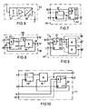
- Fig. 1 zeigt die Anordnung des Ausführungsbeispiels der erfindungsgemäßen Signalübertragungsanordnung bei einer Vergleichsschubeinrichtung.
- Fig. 2 zeigt in einemBlockschaltbild den prinzipiellen Aufbau einer Sende-/Empfangseinrichtung der in Fig. 1 gezeigten Signalübertragungsanordnung.
- In den Figuren 3 bis 14 sind die in Fig. 2 dargestellten Funktionsblöcke detailliert dargestellt.
- Fig. 1 shows the arrangement of the embodiment of the signal transmission arrangement according to the invention in a comparative thrust device.
- Fig. 2 shows in a block diagram the basic structure of a transceiver of the signal transmission arrangement shown in Fig. 1.
- The functional blocks shown in FIG. 2 are shown in detail in FIGS. 3 to 14.
Fig. 1 zeigt die prinzipielle Anordnung der erfindungsgemäßen Signalübertragungsanordnung bei einer Vergleichsschutzeinrichtung. Die Vergleichsschutzeinrichtung weist zwei Überwachungsstationen 1 und 2 auf, die jeweils an unterschiedlichen Enden 3 und 4 eines zu überwachenden Schutzabschnittes 5 einer Energieversorgungsanlage - hier einer dreiphasigen Energieübertragungsleitung - angeordnet sind. Mit Hilfe von Wandlern 6 und 7 werden an jedem Ende 3 und 4 des Schutzabschnittes 5 die jeweils dort auftretenden Phasenspannungen und/oder Phasenströme der Energieübertragungsleitung erfaßt und als Meßgrößen den jeweiligen Überwachungsstationen 1 und 2 an Meßeingängen 8 bzw. 9 zugeführt. Jede der beiden Überwachungsstationen 1 und 2 weist jeweils einen Steuerausgang 10 bzw. 11 zur Abgabe eines Abschaltsignals an einen zugeordneten steuerbaren Schalter 12 bzw. 13 auf, der an dem jeweiligen Ende 3 bzw. 4 des Schutzabschnittes 5 im Zuge der Energieübertragungsleitung angeordnet ist. Das Abschaltsignal für den jeweiligen Trennschalter 12 bzw. 13 wird in der zugeordneten Überwachungsstation 1 bzw. 2 jeweils in Abhängigkeit von den an beiden Enden 3 und 4 des Schutzabschnittes 5 erfaßten Meßgrößen erzeugt. Hierzu sind beide Überwachungsstationen 1 bzw. 2 über eine zweiadrige Signalleitung 14 miteinander verbunden, auf der die Meßgrößen oder eine aus ihnen gebildeten Vergleichsgröße zwischen beiden Überwachungsstationen 1 und 2 übertragen wird, so daß in jeder Überwachungsstation 1 bzw. 2 jeweils eine Auswertung der an beiden Enden 3 und 4 erfaßten Meßgrößen ermöglicht ist.1 shows the basic arrangement of the signal transmission arrangement according to the invention in a comparison protection device. The comparative protection device has two
Zur Überwachung der Signalleitung 14 auf Leitungsfehler, wie z. B. Leitungsbruch oder Kurzschluß, sowie zur Übertragung von sogenannten Mitnahmesignalen zwischen den beiden Überwachungsstationen 1 und 2 auf der Signalleitung 14 ist eine Signalübertragungsanordnung mit zwei Sende-/Empfangseinrichtungen 15 und 16 vorgesehen, die den jeweiligen Überwachungsstationen 1 und 2 zugeordnet und an den Enden der Signalleitung 14 angeschlossen sind. Jede Sende-/Empfangseinrichtung 15 bzw. 16 ist jeweils über einen Steuereingang 17 bzw. 18 mit einem Signalausgang 19 bzw. 20 der betreffenden Überwachungsstation 1 bzw. 2 verbunden; die Signalausgänge 19 und 20 dienen jeweils zur Abgabe eines in der betreffenden Überwachungsstation, z. B. 1, erzeugten Mitnahmesignals, das über die Signalleitung 14 an die jeweils gegenüberliegende Überwachungsstation 2 übertragen wird und dort zur Anregung der Überwachungsstation 2 im Sinne einer Abgabe eines Abschaltsignals an den zugeordneten Trennschalter 13 dient. Hierzu weist jede Sende-/Empfangseinrichtung 15 und 16 jeweils einen Ausgang 21 bzw. 22 zur Abgabe eines Abschaltsignals an einen entsprechenden Eingang 23 bzw. 24 der zugeordneten Überwachungsstation 1 bzw. 2 auf. Zur Überwachung der Signalleitung 14 weist weiterhin jede Sende-/Empfangseinrichtung 15 unb 16 jeweils einen Fehlermeldeausgang 25 bzw. 26 auf, an den hier nicht dargestellte Indikatorelemente, wie z. B. Signallampen oder Melderelais, angeschlossen sein können.To monitor the
Vor der Beschreibung der Sende-/Empfangseinrichtungen 15 und 16 soll im folgenden eine Übersicht über die Funktionsweise der Signalübertragungsanordnung entsprechend dem dargestellten Ausführungsbeispiel gegeben werden.Before the description of the transmitting / receiving
Zur Überwachung der Signalleitung 14 wird in einer Richtung von einer Sende-/Empfangseinrichtung, z. B. 15, zu der gegenüberliegenden Sende-/Empfangseinrichtung 16 über die Signalleitung 14 ein erstes Frequenzsignal übertragen, das aus einer sinusförmigen Wechselspannung mit einer Frequenz von 2 kHz besteht, die mit einer Tastzeit von 8 ms und einer nachfolgenden Tastpausenzeit von 72 ms getaktet ist. Eine Störung der Signalleitung 14 wird mit einer Verzögerung von etwa 3 Sekunden an dem Fehlermeldeausgang 26 der Sende-/Empfangseinrichtung 16 angezeigt.To monitor the
Das Mitnahmesignal kann von beiden Sende-/Empfangseinrichtungen 1 und 2 gesendet und empfangen werden. Die Übertragung eines Mitnahmesignals erfolgt in Form eines zweiten Frequenzsignals vorrangig gegenüber der Übertragung des zur Signalleitungsüberwachung dienenden ersten Frequenzsignals; das zweite Frequenzsignal besteht ebenfalls aus einer sinusförmigen Wechselspannung mit einer Frequenz von 2 kHz, die jedoch mit einer weiteren Tastzeit von 8 ms und einer weiteren Tastpausenzeit von ebenfalls 8 ms getaktet ist. Die empfangsseitige Auswertung des zweiten Frequenzsignals erfolgt durch Zählen der jeweils empfangenen Schwingungen, wobei ein fehlerfreier Empfang eines Mitnahmesignals dann erkannt wird, wenn das jeweils empfangene Frequenzsignal zweimal hintereinander eine der weiteren Tastzeit zumindest annähernd entsprechende Signaldauer und nachfolgend eine der weiteren Tastpausenzeit zumindest annähernd entsprechende Signalpause aufweist.The carry signal can be sent and received by both
Fig. 2 zeigt den prinzipellen Aufbau einer der beiden baugleichen Sende-/Empfangseinrichtungen 15 und 16. Zur Vereinfachung sind jeweils miteinander in Verbindung stehende Eingänge und Ausgänge gleich indiziert.Jede Sende-/Empfangseinrichtung enthält jeweils einen Frequenzsignalgenerator 30 mit einem Ausgang 31 und einen Frequenzsignalempfänger 32 mit einem Eingang 33. Der Ausgang 31 des Frequenzsignalgenerators 30 und der Eingang 33 des Frequenzsignalempfängers 32 sind miteinander verbunden und an einer Übertragungsseite eines Übertragers 34 angeschlossen, der an seiner anderen Übertragungsseite an der zweiadrigen Signalleitung 14 liegt.Fig. 2 shows the basic structure of one of the two identical transmitters /
Der Frequenzsignalgenerator 30 enthält einen Sinus-/Rechteckgenerator 35, der an einem Ausgang SI sine sinusförmige Wechselspannung von 2 kHz abgibt und an weiteren Ausgängen B0, B1, B2, B4, D0, D1, D2 und D4 jeweils aus der sinusförmigen Wechselspannung abgeleitete Rechtecksignale abgibt. Zwischen dem Ausgang SI des Sinus-/Rechteckgenerators 35 und dem Ausgang 31 des Frequenzsignalgenerators 30 liegt ein steuerbarer Analogschalter 36, der die seinem Eingang SI zugeführte Wechselspannung in Abhängigkeit von einem Signal an seinem Steuereingang St an den Übertrager 34 durchschaltet. Der Steuereingang St ist mit einem entsprechend bezeichneten Steuerausgang eines Taktsignalgebers 37 verbunden. Dieser ist über einen Umschalteingang M zwischen der Abgabe eines ersten Taktsignals mit einer Tast- und Tastpausenzeit von 8 ms bzw. 72 ms und einem zweiten Taktsignal mit einer weiteren Tast- und Tastpausenzeit von jeweils 8 ms umschaltbar. Der Umschalteingang M ist direkt mit einem Steuereingang 17 des Frequenzsignalgebers 30 verbunden und von der zugeordneten Überwachungsstation 1 (vgl. Fig. 1) mit dem Mitnahmesignal beaufschlagbar. Der Taktsignalgeber 37 weist weiterhin einen Funktionseingang A auf, über den die Abgabe des ersten Taktsignals abschaltbar ist. Bei dem beschriebenen Ausführungsbeispiel der erfindungsgemäßen Signalübertragungsanordnung ist in der Sende-/Empfangseinrichtung 15 der Taktgeber 37 zur Abgabe des ersten Taktsignals aktiviert, während in der gegenüberliegenden Sende-/Empfangseinrichtung 16 der betreffende Taktsignalgeber 37 bezüglich der Abgabe des ersten Taktsignals abgeschaltet ist. Zur Erzeugung der unterschiedlichen Taktsignale steht der Taktsignalgeber 37 an Takteingängen B0, D0 und D4 mit den entsprechend bezeichneten Ausgängen des Sinus-/Rechteckgenerators 35 in Verbindung. Der Taktsignalgeber 37 weist einen zusätzlichen Eingang EB auf, über den eine Unterdrückung der Abgabe des ersten Taktsignals möglich ist.The
Bei dem dargestellten Ausführungsbeispiel der erfindungsgemäßen Signalübertragungsanordnung wird also zur Überwachung der Signalleitung 14 von der Sende-/Empfangseinrichtung 15 über die Signalleitung 14 an die Sende-/Empfangseinrichtung 16 das erste Frequenzsignal mit jeweils 16 aufeinander folgenden Frequnezsignalschwingungen in 8 ms und einer darauf folgenden Signalpause von 71 ms übertragen. Zur Übertragung eines Mitnahmesignals gibt die jeweilige Sende-/Empfangseinrichtung 15 oder 16 das zweite Frequenzsignal mit jeweils 8 ms und einer nachfolgenden Signalpause von ebenfalls 8 ms ab.In the illustrated embodiment of the signal transmission arrangement according to the invention, to monitor the
Wie Fig. 3 zeigt, enthält der Sinus-/Rechteckgenerator 35 einen Sinusgenerator 38, der ausgangsseitig an dem Ausgang SI liegt und über diesen die 2 kHz-Wechselspannung abgibt. Dem Sinusgenerator 38 ist ausgangsseitig ein Rechteckimpulsformer 39 nachgeordnet, dem wiederum eine Impulszähleinrichtung, bestehend aus einem Binärzähler 40 und einem Dezimalzähler 41 nachgeordnet ist; dabei ist der Binärzähler 40 direkt über seinen Zähleingang 42 an dem Ausgang 43 des Rechteckimpulsformers 39 angeschlossen, und der Dezimalzähler 41 liegt mit seinem Zähleingang 44 an dem Ausgang B4 des Binärzählers 40. Aufgrund dieser Reihenschaltung des Binärzählers 40 und des Dezimalzählers 41 werden an den Ausgängen B0 bis B4 des Binärzählers 40 und den Ausgängen D0 bis D4 des Dezimalzählers 41 folgende rechteckförmige Zählimpulsfolgen mit den unterschiedlichen Zuständen "1" und "0" erzeugt:
- B0: 1000 Hz; 0, 5 ms "1"
und 0,5 ms "0" - B1: 500 Hz; 1 ms "1"
und 1 ms "0" - B2: 250 Hz; 2 ms "1" und 2 ms "0"
- B4: 125 Hz; 4 ms "1" und 4 ms "0"
- D0: 62,5 Hz; 8 ms "1"
und 8 ms "0" - D1: 8 ms "0", 16 ms "1", 16 ms "0", 16 ms "1", 24 ms "0"
- D2: 24 ms "0", 32 ms "1", 24 m2 "0"
- D4: 56 ms "0", 61 ms "1", 8 ms "0"
- B0: 1000 Hz; 0.5 ms "1" and 0.5 ms "0"
- B1: 500 Hz; 1 ms "1" and 1 ms "0"
- B2: 250 Hz; 2 ms "1" and 2 ms "0"
- B4: 125 Hz; 4 ms "1" and 4 ms "0"
- D0: 62.5 Hz; 8 ms "1" and 8 ms "0"
- D1: 8 ms "0", 16 ms "1", 16 ms "0", 16 ms "1", 24 ms "0"
- D2: 24 ms "0", 32 ms "1", 24 m2 "0"
- D4: 56 ms "0", 61 ms "1", 8 ms "0"
Fig. 4 zeigt den Aufbau der steuerbaren Analogschalteinrichtung 36, bestehend aus einem steuerbaren Analogschalter 45 und einem nachgeordneten Verstärker 46.4 shows the structure of the controllable
Fig. 5 zeigt den Aufbau des Taktsignalgebers 37, der einen Binärzähler 47, ein UND-Glied 48 und ein ODER-Glied 49 enthält. Diese sind in der Weise angeordnet, daß der Umschalteingang M, der Funktionseingang A, die Eingänge D0 und D4 jeweils Eingänge des UND-Gliedes 48 sind; der zusätzliche Eingang EB bildet einen invertierenden Eingang des UND-Gliedes 48. Der Eingang B0 des Taktsignalgebers 37 wird von dem Takteingang 50 des Binärzählers 47 gebildet, der weiterhin einen mit dem Umschalteingang M verbundenen Rücksetzeingang R aufweist. Das ODER-Glied 49 ist in der Weise dem Binärzähler 47 und dem UND-Glied 48 nachgeordnet, daß ein Eingang 51 des ODER-Gliedes 49 mit dem Ausgang B4 des Binärzählers 47 verbunden ist und ein weiterer Eingang 52 des ODER-Gliedes 49 an dem Ausgang des UND-Gliedes 48 angeschlossen ist. Der Ausgang des ODER-Gliedes 49 bildet den Steuerausgang St des Taktsignalgebers 37. Wird der Umschalteingang M durch Beaufschlagung mit einem Signalpegel "1" deaktiviert, so erzeugt der Taktsignalgeber 37 an seinem Steuerausgang St ein Taktsignal mit einem Tast- und Tastpausenzeit von 8 ms bzw. 72 ms; dieses erste Taktsignal kann durch Anlegen eines Signalpegels "0" an den Funktionseingang A unterdrückt werden. Durch Anlegen eines Mitnahmesignals in Form eines Signalpegels "0" an dem Umschalteingang M wird dieser aktiviert, und an dem Steuerausgang St wird das zweite Taktsignal mit einer Tast- und Tastpausenzeit von jeweils 8 ms abgegeben. Mit einem Signalpegel "1" an dem zusätzlichen Eingang EB läßt sich die Abgabe des ersten Taktsignals blockieren.5 shows the structure of the
Im folgenden wird wieder auf Fig. 2 Bezug genommen und der Aufbau des Frequenzsignalempfängers 32 beschrieben. Der Frequnzsignalempfänger 32 enthält eine Empfangsstufe 53, die an dem Eingang 33 des Frequenzsignalempfängers 32 liegt. Wie Fig. 6 zeigt, besteht diese Empfangsstufe 53 aus einem an dem Eingang 33 liegenden Bandpaßfilter 54, einer diesem nachgeordneten Verstärkerstufe 55 und einer nachfolgenden Rechteckimpulsformerstufe 56, die ausgangsseitig den Ausgang E der Empfangsstufe 53 bildet. An dem Ausgang E der Empfangsstufe 53 ist eine Signalauswerteeinrichtung 57 (Fig. 2) angeordnet, die im wesentlichen aus einer Zeitgeberstufe 58, einem Impulszähler 59, einem Impulspausenzeitzähler 60 und einer nachgeordneten Auswertelogik 61 besteht.In the following reference is made again to FIG. 2 and the structure of the
Die Zeitgeberstufe 58 ist in Fig. 7 detaillierter dargestellt und enthält ein Flip-Flop 62 mit einem nachgeordneten Dezimalzähler 63. Der Setzeingang S des Flip-Flops 62 bildet den Starteingang E der Zeitgeberstufe 58 und ist mit dem Ausgang E der Empfangsstufe 53 verbunden. Der Rücksetzeingang R des Flip-Flops 62 sowie der Rücksetzeingang des nachgeordneten Dezimalzählers 63 sind miteinander verbunden und an einem entsprechend bezeichneten Rücksetzausgang des Impulspausenzeitzählers 60 angeschlossen. Der Dezimalzähler 63 weist ein seinem Takteingang vorgeordnetes UND-Glied auf, das eingangsseitig einerseits mit dem Ausgang 64 des Flip-Flops 64 verbunden ist und andererseits mit dem Ausgang B0 des Sinus-/Rechteckgenerators 35 in Verbindung steht. Der Ausgang D4 des Dezimalzählers 63 bildet den Ausgang T der Zeitgeberstufe 58. Die Zeitgeberstufe 58 wird über ihren Starteingang E mit der ersten Schwingung eines am Eingang 33 des Frequenzsignalempfängers 32 auftretenden Frequenzsignals gestartet und erzeugt nach 8 ms einen Signalzustand "1" an ihrem Ausgang T. Diese 8 ms bilden die Ablaufzeit der Zeitgeberstufe 58 und entsprechen damit zumindest annähernd der weiteren Tastzeit des zweiten Frequenzsignals zur Übertragung eines Mitnahmesignals.The
Wie Fig. 8 zeigt, enthält der Impulszähler 59 einen Dezimalzähler 65 und ein nachgeordnetes UND-Glied 66. Der Dezimalzähler 65 steht ebenso, wie die oben bereits beschriebene Zeitgeberstufe 58 über einen Rücksetzeingang R mit dem entsprechend bezeichneten Rücksetzausgang des Impulspausenzeitzählers 60 in Verbindung. An seinem Takteingang weist der Dezimalzähler 65 ein vorgeordnetes UND-Glied auf, das eingangsseitig über einen, den Zähleingang E des Impulszählers 59 bildenden Anschluß 67 mit dem Ausgang E der Empfangsstufe 53 verbunden ist. Ein weiterer invertierenderEingang 68 des dem Takteingang des Dezimalzählers 65 vorgeordneten UND-Gliedes ist mit dem Ausgang 69 des UND-Gliedes 66 verbunden. Der Dezimalzähler 65 weist einen ersten Ausgang " 14" auf, der ein Signal angibt, wenn der Zählerstand größer oder gleich 14 ist. Ein zweiter Ausgang " 19" des Dezimalzähleres 65 gibt an, wenn der Zählerstand den Wert 19 erreicht. Dieser zweite Ausgang " 19" ist mit einem Eingang 70 des UND-Gliedes 66 verbunden, das ausgangsseitig mit einem Ausgang "19" des Impulszählers S9 verbunden ist. Ein weiterer Eingang 71 des UND-Gliedes 66 bildet einen Eingang UB des Impulszählers 59, der dazu dient, die Überlauffunktion und den Ausgang "19" des Impulszählers 59 zu blockieren.As shown in FIG. 8, the
Fig. 9 zeigt den Aufbau des Impulspausenzeitzählers 60, der einen Dezimalzähler 72 und zwei diesem nachgeordnete UND-Glieder 73 und 74 aufweist. Der Dezimalzähler 72 weist einen Takteingang mit einem vorgeordneten UND-Glied auf, das über einen Eingangsanschluß 75 mit dem Ausgang B0 des Sinus-/Rechteckgenerators 35 verbunden ist. Der Dezimalzähler 72 weist weiterhin einen Rücksetzeingang R auf, der mit dem Ausgang E der Empfangsstufe 53 und den entsprechend bezeichneten verbunden ist. Der Ausgang D1 des Dezimalzählers 72 ist mit den Rücksetzeingängen R der Zeitgeberstufe 58 und des Impulszählers 59 verbunden. Über diesen Ausgang R werden die Zeitgeberstufe 58 und der Impulszähler 59 jedesmal dann zurückgesetzt, wenn die Signalpause zwischen zwei empfangenen Frequenzsignalschwingungen größer als 1 bis 2 ms ist. Den Ausgängen D0, D1 und D2 des Dezimalzählers 72 ist das UND-Glied 73 nachgeordnet, das an seinem Ausgang "7" ein Signal abgibt, wenn an dem Eingang E des Impulspausenzeitzählers 60 für eine Zeit von 6 bis 7 ms kein Signal erscheint. Den Ausgängen D0 und D4 des Dezimalzählers 72 ist das weitere UND-Glied 74 nachgeordnet, das an seinem Ausgang "9" ein Signal abgibt, wenn an dem Eingang E des Impulspausenzeitzählers 60 für eine Zeit von 8 bis 9 ms kein Signal anliegt. Der Ausgang "9" ist mit einem invertierenden Eingang 76 des dem Takteingang des Dezimalzählers 72 vorgeordneten UND-Gliedes verbunden und blockiert den Dezimalzähler 72, sobald an dem Ausgang "9" ein Signal erscheint.FIG. 9 shows the structure of the
Der Zeitgeberstufe 58, dem Impulszähler 59 und dem Impulspausenzähler 60 ist eine Zähleinrichtung 77 zugeordnet, die in Fig. 10 detaillierter dargestellt ist. Die Zähleinrichtung 77 enthält ein Flip-Flop 78, ein nachgeordnetes UND-Glied 79 und einen diesem nachgeordneten Dezimalzähler 80. Die Zähleinrichtung 77 gibt innerhalb einer vorgegebenen Zeit den Mitnahmeentscheid frei. Im einzelnen haben die Eingänge und Ausgänge der Zähleinrichtung 77 folgende Funktionen: Der Eingang E wird mit der ersten empfangenen Frequenzsignalschwingung an dem Eingang 33 der Frequenzsignalempfangseinrichtung 32 gestartet. Ein Signal "1" an dem Eingang R stoppt die Zähleinrichtung 77 und setzt die Ausgänge auf "0" zurück. Ein Signalzustand "0" an dem Eingang M steht dann an, wenn von der eigenen Überwachungsstation, z. B. 1, ein Mitnahmesignal gesendet wird. Da in diesem Fall kein Mitnahmesignal empfangen werden soll, wird die Zähleinrichtung 77 durch den Eingang M blockiert. An dem Ausgang "8" wird 32 bis 36 ms nach dem Auftreten der ersten Frequenzsignalschwingung an dem Eingang 33 des Frequenzsignalempfängers 32 ein Signal abgegeben. Der Ausgang F nimmt gleichzeitig mit dem Auftreten der ersten Frequenzsignalschwingung an dem Eingang 33 des Frequenzsignalempfängers 32 den Zustand "1" an. Dieser Zustand gibt die Auswertung des Mitnahmesignales frei und wird 48 bis 52 ms später wieder auf "0" zurückgesetzt. Hierdurch wird eine weitere Messung des Mitnahmesignales blockiert. Der Ausgang F wird benötigt, um die sichere Auswertung der Signale auch unter Störeinflüssen sicherzustellen.A
Der Aufbau der der Zeitgeberstufe 58, dem Impulszähler 59, dem Impulspausenzeitzähler 60 und der Zähleinrichtung 77 nachgeordneten Auswertelogik 61 ist in Fig. 11 dargestellt. Die Auswertelogik 61 enthält zwei UND-Glieder 81 und 82, denen ein ODER-Glied 83 nachgeordnet ist. Das UND-Glied 81 ist eingangsseitig mit dem Ausgang T der Zeitgeberstufe 58 dem ersten Ausgang "14" des Impulszählers 59 und dem Ausgang F der Zähleinrichtung 77 verbunden; das UND-Glied 82 steht eingangsseitig mit dem Ausgang "7" des Impulspausenzeitzählers 60 und dem Ausgang F der Zähleinrichtung 77 in Verbindung. Das ODER-Glied 83 steuert einen nachgeordneten Dezimalzähler 84 über dessen Takteingang 85; der Dezimalzähler 84 ist über seinen Zählerausgang D0 mit einem invertirenden Eingang des UND-Gliedes 8lund einem nichtinvertierenden Eingang des UND-Gliedes 82 verbunden. Die Auswertelogik 61 enthält weiterhin ein weiteres ODER-Glied 86, das eingangsseitig mit den Ausgängen "19" und "9" des Impuls- bzw. Impulspausenzeitzählers 59 bzw. 60 verbunden ist und über einen invertierenden Eingang mit einem durch das mitnahmesignal beaufschlagbaren Reaktivierungseingang DE verbunden ist. Das ODER-Glied 86 ist ausgangsseitig mit einem Rücksetzeingang R des Dezimalzählers 84 und weiterhin mit dem Rücksetzeingang R der Zähleinrichtung 77 verbunden. Der Ausgang D2 des Dezimalzählers 84 bildet den Ausgang der Auswertelogik 11. Die Auswertelogik 61 verknüpft die Ausgangssignale der Zeitgeberstufe 58, des Impulszählers 59, des Impulspausenzeitzählers 60 und der Zähleinrichtung 77 in der Weise, daß der Ausgang R den Zustand "1" annimmt, wenn die Eingänge "9" oder "19" mit dem Zustand "1" beaufschlagt sind oder wenn der Eingang M den Zustand "0" aufweist. Dies ist dann der Fall, wenn bei einem empfangenen Frequenzsignal mehr als 9 Frequenzsignalschwingungen aufeinanderfolgen oder wenn die Signalpause 19 ms erreicht oder überschreitet. In diesem Fall ist kein Mitnahmesignal bzw. zweites Frequenzsignal empfangen worden und der Signalzustand an dem Ausgang D2 der Auswertelogik 61 ist "0". An dem Ausgang D2 der Auswertelogik 61 wird dagegen ein Ausgangssignal "1" abgegeben, wenn innerhalb einer Zeit von maximal 48 bis 52 ms vom Beginn der ersten am Eingang 33 des Frequenzsignalempfängeres 32 empfangenen Frequenzsignalschwingung eines Frequenzsignales an jeweils zweimal die Grenzwerte für die Tastzeiten und die Tastpausenzeiten mit 14 bis maximal 19 aufeinanderfolgenden Schwingungsperioden in einer Zeit von 7 bis 8 ms und einer nachfolgenden Tastpausenzeit von mindestens 6 bis maximal 9 ms in der Reihenfolge Tastzeit - Tastpausenzeit - Tastzeit - Tastpausenzeit eingehalten werden.The structure of the
In Abhängigkeit von dem Ausgangssignal an dem Ausgang D2 der Auswertelogik 61 wird eine nachgeordnete Verzögerungsstufe 87 gesteuert, die in Fig. 12 näher dargestellt ist. Die Verzögerungsstufe 87 enthält ein eingangsseitig mit dem Ausgang D2 der Auswertelogik 61 und dem Ausgang "8" der Zähleinrichtung 77 verbundenes UND-Glied 88, einen Dezimalzähler 89 und ein Flip-Flop 90. An dem Ausgang 21 der Verzögerungsstufe 87 wird ein Abschaltsignal für die zugeordnete Überwachungsstation, z. B. 1, erzeugt, wenn nach einer minimalen Zeit von 32 bis 36 ms nach dem ersten Auftreten einer ersten Frequenzsignalschwingung an dem Eingang 33 des Frequenzsignalempfängers 32 und einer maximalen Zeit von 48 bis 52 ms an dem Ausgang D2 der Auswertelogik 61 ein Ausgangssignal abgegeben wird. Der Eingang D4 der Verzögerungsstufe 87 dient zur Steuerung des Dezimalzählers 80 und ist mit dem entsprechenden Ausgang des Sinus-Rechteckgenerators 35 verbunden. Durch den Dezimalzähler 80 wird das Abschaltsignal an dem Ausgang 21 etwa 560 bis 640 ms nach dem Rückfallen des Eingangssignales an dem Eingang D2 auf "0" verzögert zurückgesetzt. Dadurch steht an dem Ausgang 21 der Verzögerungsstufe 87 ein Abschaltsignal für die zugeordnete Überwachungsstufe, z. B. 1, an, wenn in dem Frequenzsignalempfänger ein Frequenzsignal empfangen worden ist, das dem von der jeweiligen Gegenstation ausgesandten Mitnahmesignal in Form des zweiten Frequenzsignales entspricht.Depending on the output signal at the output D2 of the
Zur Überwachung der Signalleitung 14 ist eine Zeitablaufstufe 91 vorgesehen, die entsprechend der Darstellung in Fig. 13 aus einem Dezimalzähler besteht. Dieser Dezimalzähler ist mit seinem Zähleingang D4 an dem entsprechend bezeichneten Ausgang des Sinus-/Rechteckgenerators 35 angeschlossen. Der Rücksetzeingang "14" der Zeitablaufstufe 91 ist mit dem gleichnamigen Ausgang des Impulszählers 59 verbunden. Der Zählausgang "38" des die Zeitablaufstufe 91 bildenden Dezimalzählers entspricht dem Fehlermeldeausgang 25 der Sende-/Empfangseinrichtung 15 bzw. 16. Werden für eine Zeit von 2960 bis 3040 ms keine Frequenzsignale mit mindestens 14 Wechselspannungsperioden je Tastzeit von 8 ms empfangen, so wird an dem Ausgang 25 ein Fehlermeldesignal abgegeben und so eine Störung der Signalleitung 14 gemeldet.A
Eine in dem Frequenzsignalempfänger 32 angeordnete Blockierstufe 92, die in Fig. 14 näher dargestellt ist, blockiert die Steuerung des Frequenzsignalgenerators 30 und die Auswertung der empfangenen Frequenzsignale in der Signalauswerteeinrichtung 57 unter folgenden Bedingungen: Wenn an dem Eingang 33 des Frequenzsignalempfängers 32 Frequenzsignale empfangen werden und die eigene Sende-/Empfangseinrichtung nicht sendet, so wird der Ausgang EB auf "1" gesetzt und gibt damit an, daß die empfangenen Signale von der jeweiligen Gegenstation gesendet werden. Durch den Ausgang EB wird der Taktsignalgeber 37 in der Weise gesteuert, daß die Abgabe des ersten Taktsignals zur Überwachung der Signalleitung 14 blockiert wird. Das Signal "1" an dem Ausgang EB der Blockierstufe 92 wird selbsttätig durch Zählen der Impulse an dem Eingang B4 nach einer Zeit von 56 bis 64 ms zurückgesetzt. Über den Ausgang UB wird in dem Impulszähler 59 ein Zählüberlauf gesperrt, wenn während einer Zeit von einer bis zwei Millisekunden nach dem Senden eines eigenen Frequenzsignals mit einer Tastzeit von 8 ms der Ausgang EB den Zustand "1" angenommen hat. Dadurch wird verhindert, daß der Impulszähler 59 Frequenzsignalschwingungen eines von der eigenen Sende-/Empfangseinrichtung z.B. 15 erzeugten Frequenzsignals mit den Frequenzsignalschwingungen eines nachfolgend empfangenen Frequenzsignals von der gegenüberliegenden Sende-/Empfangseinrichtung 16 zusammenzählt.A blocking
Claims (8)
daß jeder Frequenzsignalgenerator (30) einen durch ein Mitnahmesignal aktivierbaren Steuereingang (17) aufweist,
daß der Frequenzsignalgenerator (30) der einen Sende-/Empfangseinrichtung (1) zur Abgabe eines mit einer vorgegebenen Tast- und Tastpausenzeit getakteten ersten Frequenzsignals bei deaktiviertem Steuereingang (17) ausgebildet ist,
daß der Ausgang (31) des Frequenzsignalgenerators (30) in der anderen Sende-/Empfangseinrichtung (2) bei deaktiviertem Steuereingang (17) abgeschaltet ist,
daß beide Frequenzsignalgeneratoren (30) durch steuereingangsseitige Beaufschlagung mit dem Mitnahmesignal jeweils zur ausgangsseitigen Abgabe eines zweiten getakteten Frequenzsignals mit einer weiteren vorgegebenen Tast- und Tastpausenzeit aktivierbar sind,
daß jeder Frequenzsignalempfänger (32) jeweils eine an seinem Eingang (3) angeschlossene Signalauswerteeinrichtung (57) enthält, die ausgangsseitig ein Abschaltsignal für den der betreffenden Überwachungsstation (1, 2) zugeordneten Schalter (12, 13) in Abhängigkeit davon abgibt, daß zumindest einmalig an dem Eingang (33) des Frequenzsignalempfängers (32) ein Frequenzsignal mit einer der weiteren Tastzeit zumindest annähernd entsprechenden Signaldauer und nachfolgend einer der weiteren Tastpausenzeit zumindest annähernd entsprechenden Signalpause auftritt,
und daß jeder Frequenzsignalempfänger (32) eine Zeitablaufstufe enthält, die einen dem Eingang (33) des Frequenzsignalempfängers (32) nachgeordneten Rücksetzeingang aufweist und ausgangsseitig den Fehlermeldeausgang (25) des betreffenden Frequenzsignalempfängers (32) bildet.1.Signal transmission arrangement for a comparative protection device, in which measured values are recorded in two monitoring stations at two ends of a protective section of an energy transmission system to be monitored and in each monitoring station a switch-off signal for a switch at the respective end of the protective section depending on the measured values recorded in both monitoring stations is generated with a signal line connecting the two monitoring stations for the transmission of the measured variables or a comparison variable formed from them and with two transmitting / receiving devices, each having a frequency signal generator and a frequency signal receiver with an error reporting output and a transmitter, the frequency signal generator being one of the two transmitters - / Receivers on the output side via the associated transmitter is connected to one end of the signal line and the frequency signal receiver of the other transmit / E Receiving device is connected on the input side via the corresponding transmitter to the other end of the signal line, characterized in that in both transmitting / receiving devices (1, 2) the output (31) of the frequency signal generator (30) with the input (33) of the frequency signal receiver ( 32) is connected
that each frequency signal generator (30) has a control input (17) which can be activated by a carry signal,
that the frequency signal generator (30) of the one transmitting / receiving device (1) is designed to emit a first frequency signal clocked with a predetermined keying and keying pause time when the control input (17) is deactivated,
that the output (31) of the frequency signal generator (30) in the other transmitting / receiving device (2) is switched off when the control input (17) is deactivated,
that both frequency signal generators (30) can be activated with a further predetermined keying and keying pause time by supplying the driving signal on the control input side to the output side in each case for emitting a second clocked frequency signal,
that each frequency signal receiver (32) contains a signal evaluation device (57) connected to its input (3), which outputs a switch-off signal for the switch (12, 13) assigned to the relevant monitoring station (1), depending on the fact that at least once a frequency signal occurs at the input (33) of the frequency signal receiver (32) with a signal duration which at least approximately corresponds to the further keying time and subsequently a signal pause which at least approximately corresponds to the further keying pause time,
and that each frequency signal receiver (32) contains a timing stage which has a reset input downstream of the input (33) of the frequency signal receiver (32) and forms the error signal output (25) of the frequency signal receiver (32) concerned on the output side.
daß der Analogschalteinrichtung (36) ein diese über seinen Steuerausgang (St) steuernder Taktsignalgeber (37) zugeordnet ist,
daß dem Sinusgenerator (38) ein Rechteckimpulsformer (39) und diesem eine Impulszähleinrichtung (40, 41) zur Abgabe von Zählimpulsen nachgeordnet ist,
daß die Impulszähleinrichtung (40, 41) ausgangsseitig mit dem Taktsignalgeber (37) in Verbindung steht, der aus den Zählimpulsen ein erstes Taktsignal mit der vorgegebenen Tast- und Tastpausenzeit und ein weiteres Taktsignal mit der weiteren Tast- und Tastpausenzeit ableitet und
daß der Taktsignalgeber (37) einen den Steuereingang (17) des Frequenzsignalgenerators bildenden Umschalteingang (M) aufweist, bei dessen Beaufschlagung mit dem Mitnahmesignal der Taktsignalgeber (37) von der Abgabe des ersten Taktsignals an seinem Steuerausgang (St) auf die Abgabe des zweiten Taktsignals umschaltbar ist.4. Signal transmission arrangement according to one of claims 1 to 3, characterized in that each frequency signal generator (30) contains a sine generator (38) which is on the output side via a controllable analog switching device (36) at the output (31) of the frequency signal generator (30),
that the analog switching device (36) is assigned a clock signal generator (37) controlling it via its control output (St),
that the sine wave generator (38) is followed by a rectangular pulse shaper (39) and this a pulse counting device (40, 41) for delivering counting pulses,
that the pulse counting device (40, 41) is connected on the output side to the clock signal generator (37) which derives a first clock signal with the predetermined keying and keying pause time and a further clock signal with the further keying and keying pause time from the counting pulses and
that the clock signal generator (37) has a switching input (M) forming the control input (17) of the frequency signal generator, when it is acted upon by the driving signal, the clock signal generator (37) from the output of the first clock signal at its control output (St) to the output of the second clock signal is switchable.
daß jeweils ein Impulszähler (59) mit seinem Zähleingang (E) dem Eingang (33) des betreffenden Frequenzsignalempfängers (32) nachgeordnet ist,
daß der Zeitgeberstufe (58) und dem Impulszähler (59) eine Auswertelogik (61) nachgeordnet ist, die zur Erzeugung des Abschaltsignals den Impulszähler (59) auf Erreichen eines minimalen Zählerstandes während der Ablaufzeit überwacht und die Erzeugung des Abschaltsignals unterdrückt, sobald der Impulszähler (59) einen vorgegebenen maximalen Zählerstand erreicht.6. Signal transmission arrangement according to one of the preceding claims, characterized in that each signal evaluation device (57) for detecting the further scanning time at least approximately corresponding signal duration of the frequency signal received in each case contains a timer stage (58) with its start input (E) the input (33 ) of the associated frequency signal receiver (32) is subordinate and emits an output signal with an expiry time that at least approximately corresponds to the further keying time,
that a pulse counter (59) with its counting input (E) is arranged downstream of the input (33) of the frequency signal receiver (32) concerned,
that the timer stage (58) and the pulse counter (59) is followed by evaluation logic (61) which monitors the pulse counter (59) for generating the switch-off signal for reaching a minimum counter reading during the expiry time and suppresses the generation of the switch-off signal as soon as the pulse counter ( 59) reaches a predetermined maximum counter reading.
daß dem Impulspausenzeitzähler (60) die Auswertelogik (61) nachgeordnet ist, die zur Erzeugung des Abschaltsignals den Impulspausenzeitzähler (60) auf Erreichen eines weiteren minimalen Zählerstandes überwacht und die Erzeugung des Abschaltsignals unterdrückt, sobald ein vorgegebener weiterer maximaler Zählerstand erreicht wird.7. Signal transmission arrangement according to claim 6, characterized in that each signal evaluation device (57) for detecting the further pause time at least approximately corresponding signal pause of the frequency signal received in each case contains a clock-controlled pulse pause counter (60) which, with its reset input (E), contains the input (33). of the assigned frequency signal receiver (32) and
that the pulse pause counter (60) is followed by the evaluation logic (61) which monitors the pulse pause counter (60) for generating the switch-off signal for reaching a further minimum counter reading and suppresses the generation of the switch-off signal as soon as a predetermined further maximum counter is reached.
Priority Applications (1)
| Application Number | Priority Date | Filing Date | Title |
|---|---|---|---|
| AT86730150T ATE54779T1 (en) | 1985-10-15 | 1986-10-03 | SIGNAL TRANSMISSION ARRANGEMENT FOR A COMPARISON PROTECTION DEVICE. |
Applications Claiming Priority (2)
| Application Number | Priority Date | Filing Date | Title |
|---|---|---|---|
| DE3537072 | 1985-10-15 | ||
| DE19853537072 DE3537072A1 (en) | 1985-10-15 | 1985-10-15 | SIGNAL TRANSMISSION ARRANGEMENT FOR A COMPARATIVE PROTECTION DEVICE |
Publications (2)
| Publication Number | Publication Date |
|---|---|
| EP0222682A1 true EP0222682A1 (en) | 1987-05-20 |
| EP0222682B1 EP0222682B1 (en) | 1990-07-18 |
Family
ID=6283832
Family Applications (1)
| Application Number | Title | Priority Date | Filing Date |
|---|---|---|---|
| EP86730150A Expired - Lifetime EP0222682B1 (en) | 1985-10-15 | 1986-10-03 | Signal transmission system for a comparison protection device |
Country Status (3)
| Country | Link |
|---|---|
| EP (1) | EP0222682B1 (en) |
| AT (1) | ATE54779T1 (en) |
| DE (2) | DE3537072A1 (en) |
Cited By (2)
| Publication number | Priority date | Publication date | Assignee | Title |
|---|---|---|---|---|
| EP0810714A2 (en) * | 1996-05-29 | 1997-12-03 | Schweitzer Engineering Laboratories, Inc. | System of communicating output function status indications between two or more power system protective relays |
| WO2002049176A1 (en) * | 2000-12-13 | 2002-06-20 | Siemens Aktiengesellschaft | System and method for the data transmission of digital transmission data |
-
1985
- 1985-10-15 DE DE19853537072 patent/DE3537072A1/en not_active Withdrawn
-
1986
- 1986-10-03 DE DE8686730150T patent/DE3672755D1/en not_active Expired - Fee Related
- 1986-10-03 EP EP86730150A patent/EP0222682B1/en not_active Expired - Lifetime
- 1986-10-03 AT AT86730150T patent/ATE54779T1/en active
Non-Patent Citations (2)
| Title |
|---|
| BROWN BOVERI MITTEILUNGEN, Band 55, Nr. 4/5, April/Mai 1968, Seiten 236-240, CH; A. ZOTTLER: "Schutzsignal-Übertragungsgeräte Typ NSD" * |
| BULL. SEV/VSE, Band 11, Nr. 65, 1. Juni 1974, Seiten 821-827, CH; F. EGGIMANN et al.: "Fernauslösetechnik - eine besondere Form von Nachrichtenübertragung" * |
Cited By (4)
| Publication number | Priority date | Publication date | Assignee | Title |
|---|---|---|---|---|
| EP0810714A2 (en) * | 1996-05-29 | 1997-12-03 | Schweitzer Engineering Laboratories, Inc. | System of communicating output function status indications between two or more power system protective relays |
| EP0810714A3 (en) * | 1996-05-29 | 1998-10-07 | Schweitzer Engineering Laboratories, Inc. | System of communicating output function status indications between two or more power system protective relays |
| WO2002049176A1 (en) * | 2000-12-13 | 2002-06-20 | Siemens Aktiengesellschaft | System and method for the data transmission of digital transmission data |
| US7330512B2 (en) | 2000-12-13 | 2008-02-12 | Siemens Aktiengesellschaft | System and method for the data transmission of digital transmission data |
Also Published As
| Publication number | Publication date |
|---|---|
| EP0222682B1 (en) | 1990-07-18 |
| ATE54779T1 (en) | 1990-08-15 |
| DE3672755D1 (en) | 1990-08-23 |
| DE3537072A1 (en) | 1987-04-16 |
Similar Documents
| Publication | Publication Date | Title |
|---|---|---|
| EP0964549B1 (en) | Monitoring circuit for a data transmission network | |
| EP0031046A2 (en) | Device for data secure control and supervision of electric equipments | |
| DE1755204A1 (en) | Signal transmission system | |
| DE2338882C2 (en) | Method and telecontrol system for switching electrical consumers on and off | |
| DE1513708B2 (en) | PHASE COMPARISON PROTECTIVE ARRANGEMENT | |
| DE2903860C2 (en) | Device for direct current supply to a consumer and for the simultaneous transmission of information via a pair of wires | |
| EP0222682B1 (en) | Signal transmission system for a comparison protection device | |
| DE102009050692B4 (en) | Security communication system for signaling system states | |
| DE2156873B2 (en) | METHOD AND DEVICE FOR REMOTE CONTROL BY MEANS OF THE INDIVIDUAL COMMANDS PULSE IMAGES | |
| DE2923716A1 (en) | METHOD FOR TRANSMITTING BINARY SIGNALS VIA A FOREIGN WIRE NETWORK | |
| DE2719223C2 (en) | Arrangement for converting alarm signals between a digital communication system and a central operational monitoring system | |
| DE2134783B2 (en) | Fault detector for repeaters in PCM transmission link - uses momentary break in remote supply to prepare for testing | |
| DE2725152C2 (en) | Monitoring system for electronic assemblies or devices in wired telecommunications systems | |
| DE2719248C2 (en) | Frequency-selective character receiver for telecommunications, in particular telephone systems | |
| DE2702551C2 (en) | Circuit for monitoring signals | |
| DE1032346B (en) | Error reporting and monitoring system for radio relay stations of radio link lines, especially for microwave radio amplifiers | |
| DE3346527A1 (en) | METHOD AND ARRANGEMENT FOR THE FAULT-SAFE ALARM EVALUATION OF A DETECTING LINE OF A DANGER DETECTING SYSTEM | |
| EP0054643B1 (en) | Remote monitoring installation with at least one arrangement for the transmission of messages according to a time division multiplex-frequency division multiplex procedure | |
| DE2358272C2 (en) | Device for determining errors in a message transmission system for pulse code modulation | |
| AT226281B (en) | Device for the detection of operating errors in pulse regenerating repeaters | |
| DE737381C (en) | Circuit arrangement for telegraph systems, in which the change between character and separation pulses and vice versa is transmitted by changing the phase of a carrier current | |
| EP0622734B1 (en) | Interface | |
| DE3138650A1 (en) | METHOD FOR MONITORING A RADIO RECEIVING SYSTEM | |
| DE4409880C2 (en) | Method for monitoring the auxiliary wires of a differential protection arrangement | |
| DE3519326C1 (en) | Circuit arrangement for remote-controlled slave-clock lines |
Legal Events
| Date | Code | Title | Description |
|---|---|---|---|
| PUAI | Public reference made under article 153(3) epc to a published international application that has entered the european phase |
Free format text: ORIGINAL CODE: 0009012 |
|
| AK | Designated contracting states |
Kind code of ref document: A1 Designated state(s): AT BE CH DE FR IT LI NL SE |
|
| 17P | Request for examination filed |
Effective date: 19871027 |
|
| 17Q | First examination report despatched |
Effective date: 19891004 |
|
| GRAA | (expected) grant |
Free format text: ORIGINAL CODE: 0009210 |
|
| AK | Designated contracting states |
Kind code of ref document: B1 Designated state(s): AT BE CH DE FR IT LI NL SE |
|
| PG25 | Lapsed in a contracting state [announced via postgrant information from national office to epo] |
Ref country code: NL Effective date: 19900718 Ref country code: FR Effective date: 19900718 Ref country code: BE Effective date: 19900718 |
|
| REF | Corresponds to: |
Ref document number: 54779 Country of ref document: AT Date of ref document: 19900815 Kind code of ref document: T |
|
| REF | Corresponds to: |
Ref document number: 3672755 Country of ref document: DE Date of ref document: 19900823 |
|
| ITF | It: translation for a ep patent filed |
Owner name: STUDIO JAUMANN |
|
| EN | Fr: translation not filed | ||
| NLV1 | Nl: lapsed or annulled due to failure to fulfill the requirements of art. 29p and 29m of the patents act | ||
| PLBE | No opposition filed within time limit |
Free format text: ORIGINAL CODE: 0009261 |
|
| STAA | Information on the status of an ep patent application or granted ep patent |
Free format text: STATUS: NO OPPOSITION FILED WITHIN TIME LIMIT |
|
| 26N | No opposition filed | ||
| ITTA | It: last paid annual fee | ||
| PGFP | Annual fee paid to national office [announced via postgrant information from national office to epo] |
Ref country code: AT Payment date: 19930929 Year of fee payment: 8 |
|
| PGFP | Annual fee paid to national office [announced via postgrant information from national office to epo] |
Ref country code: SE Payment date: 19940912 Year of fee payment: 9 |
|
| PG25 | Lapsed in a contracting state [announced via postgrant information from national office to epo] |
Ref country code: AT Effective date: 19941003 |
|
| PGFP | Annual fee paid to national office [announced via postgrant information from national office to epo] |
Ref country code: DE Payment date: 19941216 Year of fee payment: 9 |
|
| PGFP | Annual fee paid to national office [announced via postgrant information from national office to epo] |
Ref country code: CH Payment date: 19950118 Year of fee payment: 9 |
|
| EAL | Se: european patent in force in sweden |
Ref document number: 86730150.9 |
|
| PG25 | Lapsed in a contracting state [announced via postgrant information from national office to epo] |
Ref country code: SE Effective date: 19951004 |
|
| PG25 | Lapsed in a contracting state [announced via postgrant information from national office to epo] |
Ref country code: LI Effective date: 19951031 Ref country code: CH Effective date: 19951031 |
|
| REG | Reference to a national code |
Ref country code: CH Ref legal event code: PL |
|
| EUG | Se: european patent has lapsed |
Ref document number: 86730150.9 |
|
| PG25 | Lapsed in a contracting state [announced via postgrant information from national office to epo] |
Ref country code: DE Effective date: 19960702 |
|
| PG25 | Lapsed in a contracting state [announced via postgrant information from national office to epo] |
Ref country code: IT Free format text: LAPSE BECAUSE OF NON-PAYMENT OF DUE FEES;WARNING: LAPSES OF ITALIAN PATENTS WITH EFFECTIVE DATE BEFORE 2007 MAY HAVE OCCURRED AT ANY TIME BEFORE 2007. THE CORRECT EFFECTIVE DATE MAY BE DIFFERENT FROM THE ONE RECORDED. Effective date: 20051003 |