EP0222691A2 - Device for the preservation of the fibres of glass fibre cables in the distribution assemblies of a telecommunication network - Google Patents
Device for the preservation of the fibres of glass fibre cables in the distribution assemblies of a telecommunication network Download PDFInfo
- Publication number
- EP0222691A2 EP0222691A2 EP86730176A EP86730176A EP0222691A2 EP 0222691 A2 EP0222691 A2 EP 0222691A2 EP 86730176 A EP86730176 A EP 86730176A EP 86730176 A EP86730176 A EP 86730176A EP 0222691 A2 EP0222691 A2 EP 0222691A2
- Authority
- EP
- European Patent Office
- Prior art keywords
- cassette
- winding
- receptacle
- housing
- fibers
- Prior art date
- Legal status (The legal status is an assumption and is not a legal conclusion. Google has not performed a legal analysis and makes no representation as to the accuracy of the status listed.)
- Granted
Links
- 239000003365 glass fiber Substances 0.000 title claims description 36
- 230000000712 assembly Effects 0.000 title 1
- 238000000429 assembly Methods 0.000 title 1
- 238000004321 preservation Methods 0.000 title 1
- 239000000835 fiber Substances 0.000 claims abstract description 50
- 238000004804 winding Methods 0.000 claims description 60
- 238000005452 bending Methods 0.000 description 4
- 125000006850 spacer group Chemical group 0.000 description 2
- 238000003780 insertion Methods 0.000 description 1
- 230000037431 insertion Effects 0.000 description 1
- 239000000463 material Substances 0.000 description 1
- 238000000034 method Methods 0.000 description 1
- 238000005192 partition Methods 0.000 description 1
Images


Classifications
-
- G—PHYSICS
- G02—OPTICS
- G02B—OPTICAL ELEMENTS, SYSTEMS OR APPARATUS
- G02B6/00—Light guides; Structural details of arrangements comprising light guides and other optical elements, e.g. couplings
- G02B6/44—Mechanical structures for providing tensile strength and external protection for fibres, e.g. optical transmission cables
- G02B6/4439—Auxiliary devices
- G02B6/444—Systems or boxes with surplus lengths
- G02B6/4453—Cassettes
- G02B6/4455—Cassettes characterised by the way of extraction or insertion of the cassette in the distribution frame, e.g. pivoting, sliding, rotating or gliding
-
- G—PHYSICS
- G02—OPTICS
- G02B—OPTICAL ELEMENTS, SYSTEMS OR APPARATUS
- G02B6/00—Light guides; Structural details of arrangements comprising light guides and other optical elements, e.g. couplings
- G02B6/44—Mechanical structures for providing tensile strength and external protection for fibres, e.g. optical transmission cables
- G02B6/4439—Auxiliary devices
- G02B6/444—Systems or boxes with surplus lengths
- G02B6/4452—Distribution frames
- G02B6/44526—Panels or rackmounts covering a whole width of the frame or rack
-
- G—PHYSICS
- G02—OPTICS
- G02B—OPTICAL ELEMENTS, SYSTEMS OR APPARATUS
- G02B6/00—Light guides; Structural details of arrangements comprising light guides and other optical elements, e.g. couplings
- G02B6/44—Mechanical structures for providing tensile strength and external protection for fibres, e.g. optical transmission cables
- G02B6/4439—Auxiliary devices
- G02B6/444—Systems or boxes with surplus lengths
- G02B6/4453—Cassettes
- G02B6/4454—Cassettes with splices
Definitions
- the invention relates to a device for storing the fibers of fiber optic cables in distribution devices in the telecommunications network according to the preamble of claim 1.
- the splicing reserve is necessary because the splice itself is not reusable and each time the splicing process is repeated, about 30 mm of the fiber length is lost.
- the splice reserve accommodated in a splice cassette has a length of approximately 1 m.
- the splice tray must be fed to a splice table for splicing.
- an internal distribution cable for bridging the distance between the fastening point and the space for the arrangement of the splice cassette in the housing and a movable feed cable are provided as partial lengths of the glass fiber cable between a fastening point of the glass fiber cable and the movable splice cassette provided with the splice reserve.
- the movable feed cable serves to bridge the distance between the space for the arrangement of the splice cassette and a splice table on which the splice cassette is placed for splicing.
- the splice cassette is part of a guide rod which is inserted into the housing.
- the glass fibers are freely wrapped around the splice cassette, with the risk of damage, in particular breaking, of the glass fibers.
- the fiber optic cable can be kinked when the rod provided with the splice cassette is inserted into the housing, which also increases the risk of the fiber optic cable breaking.
- the housing of the known device requires a relatively large overall depth, which is due to the length of the guide rod for the splice cassette.
- the invention is therefore based on the object to provide a device of the generic type which is suitable for storing the ends of fiber optic cables, ie. H. the splice reserve recorded on the splice cassette and the length of the supply cable in distribution devices in the telecommunication network enables easy handling with a small space requirement of the device.
- the cassette which accommodates at least the splicing reserve, but expediently also the movable feed cable as partial lengths of the glass fiber cable, is accommodated in a cassette box provided with a removal opening which is mounted in the housing of the distributor device.
- the storage is provided in such a way that the cassette case can be moved from its essentially vertical storage position in the housing into its essentially horizontal removal position with the removal opening at the top. In the removal position, the cassette can easily be removed from the removal opening of the cassette box in order to feed the cassette, for example, to a splice table, the movable feed cable being unwound from a winding body as part of the length of the glass fiber cable.
- the cassette box is designed to accommodate a plurality of cassettes lying next to one another.
- the cassette box according to the invention can be accommodated as a single piece in the housing of a cable end closure or a distribution box.
- the housing for storing the cassette box can also be designed as a frame for a plurality of cassette boxes arranged one above the other.
- the cassette box is by means of a slide-tilt bearing in the housing or in Stored frame to a particularly convenient vertical storage position of the 'pack case in the housing or frame and the substantially horizontal removal position with overhead withdrawal opening of the cassette case to enable the allowable bending radius of the fiber optic cable can be maintained.
- the cassette box which receives the cassettes with fiber optic cables wound on bobbins, is arranged using the permissible bending radii of the fiber optic cables in such a way that the greatest possible bending radii for the supplied fiber optic cables or fiber optic bundles are available when the cassette box is inserted and folded out.
- the invention is explained in more detail below with reference to two embodiments of the device for storing the ends of glass fiber cables in distribution devices in the telecommunications network with winding bodies in the form of a cassette.
- the device for storing the fibers of fiber optic cables in distribution devices in the telecommunications network comprises a cassette box 1 made of floor 2, two longitudinal side walls 3, 4 and two end walls 5, 6, which enclose a removal opening 7.
- the cassette box 1 is mounted in a housing 9 or in a frame 10 by means of a slide-tilt bearing 8.
- the slide-tilt bearing 8 is composed of two angle pieces 11 arranged on the end wall 5 of the cassette box 1 near the removal opening 7, a tilt axis 12 mounted in the latter and two guide rails 13 fixedly mounted in the housing 9 or frame 10 by means of a spacer plate 13 ′ formed, which serve as a sliding bearing for the tilt axis 12 and are guided perpendicular to the open side of the housing 9 or the frame 10 and end on the open side.
- the guide rails 13 each have a guide slot 14 for the tilt axis 12.
- the guide rails 13 are fastened on the spacer plate 13 ′. In the installed state, this serves to ensure sufficient stability of the slide - tilt bearing 8 and, when the cassette case 1 is removed, enables the interior of the housing 9 or the frame 10 to be fully freely accessible.
- the distributor device is a cable end closure, which is formed from the box-shaped housing 9 and a closure cover 15.
- a single cassette box 1 is used in the housing 9. This is located within the housing 9 in its storage position, in which the cassette box 1 bears against a stop 16 which is fastened to the inside of the upper wall of the housing 9 and secured by a locking spring 17 which is behind a catch 18 on the inside of the snaps top wall of the housing 9.
- the cassette box 1 can be pulled out of the housing 9 after removing the closure cover 15 and unlocking the locking spring 17, the longitudinal walls 3, 4 and the end walls 5, 6 of the cassette box 1 being brought out parallel to the respective walls of the housing 9.
- the axis 12 is guided within the guide slots 14 of the two guide rails 13.
- the cassette box 1 can be pivoted out by approximately 90 ° into its essentially horizontal removal position, in which the receiving opening 7 is directed upwards.
- the tilt axis 12 forms a tilt joint.
- the end face 5 of the cassette box 1 abuts stops 19 which are fixedly attached to the inside of the side walls on the open side of the housing 9.
- cassettes 20 for the movable feed cable of the fiber optic cable 23 are arranged next to one another, which each contain winding bodies 59 for the fiber optic cable 23 and splice cassettes 59 for the splice reserve 52 of the fiber optic cable 23.
- the fiber optic cables 23 fed in via cable entries 22 of the housing 9 are, in the removal position of the cassette box 1, fed in an arc shape to the individual winding bodies 59 arranged in the cassette box 1 and provided with splice cassettes 58.
- the glass fiber cables 23 In the vertical storage position of the cassette box 1, which is also shown in FIG. 1, the glass fiber cables 23 still run, using the winding radius R of the winding body 59, in an arc from the cable entries 22 to the winding bodies 59 inside the cassette box 1.
- the glass fiber cables 23 are both in the The storage position of the cassette box 1 in the housing 9 and in the removal position of the cassette box 1 are stored in a break-proof manner using the permissible bending radius.
- a device 25 for fastening a pocket 26 for kink-free, space-saving stowing of the shunting fibers 24 inside the cassette box 1 is provided on the removal opening 7 of the cassette box 1.
- the device 25 comprises a bolt 27 spanning the removal opening 7 for fastening the pocket 26 by means of push-button-like fastening elements 29, which is supported on the cassettes 20 located in the cassette box 1 and at the same time prevents the cassettes 20 from falling out.
- the bag 26 * takes up the shunting fibers 24 routed within the cassette box 1 and enables the inaccurate feed length of the shunting fibers 24 to be compensated for by means of freely selectable fastening holes 43.
- a plurality of cassette boxes 1 are arranged one above the other in a partition frame 10 for glass fiber cables 23.
- Each cassette box 1 is supported by means of a slide-tilt bearing 8, which is designed analogously to the first embodiment shown in FIGS. 1 and 2, on a respective mounting bracket 30, which in turn is firmly connected to the frame 10.
- cassette boxes 1 according to the second embodiment shown in FIGS. 4 and 5 can be moved in the same way from their essentially vertical storage position into their essentially horizontal removal position with the removal opening 7 lying on top, as in the first embodiment according to FIG. 1 and 2 has been described in more detail.
- the approximately U-shaped frame 10 in horizontal cross section bears approximately each semicircular guide body 31 for shunting fibers 24 above each fastening bracket 30 fastened to it. which interconnect the glass fibers 23 located in the individual cassette boxes 1 and wound on the winding bodies 59 of the cassettes 2.
- the guide bodies 31 are arranged on the inside of the frame 10 between the frame 10 and the cassette boxes 1 located in the storage position.
- a transport elevator 32 is mounted on the inside of the U-shaped frame 10, which runs behind the cassette boxes 1 located in their vertical storage position and behind the guide bodies 31.
- the transport elevator 32 for the maneuvering fibers 24 is formed from deflection rollers 33 mounted on the upper and lower ends of the frame 10 and a transport rope 34 guided around the latter, with which a transport clamp 35 for one or more maneuvering fibers 24 can be detachably connected.
- the transport clamp 35 carries a clamp 40 for clamping one or more maneuvering fibers 24.
- maneuvering fibers 24 can easily be laid within the frame 10 from one cassette box 1 to the other cassette box 1 without opening the cassette boxes 1 in between or expand.
- the transport clamp 35 can be freely connected to the transport cable 34 and can be removed from the frame 10 for fastening one or more shunting fibers 24.
- FIG. 5 shows, in horizontal cross section, the guidance of a plurality of fiber optic cables 23 and shunting fibers 24.
- guide tubes 41 of different lengths are attached to the back of the frame 10, the outlet openings 42 of which are each assigned to a cassette box 1.
- the slide-tilt bearing 8 is removably mounted both in the housing 9 and in the frame 10.
- the ease of disassembly is achieved in that the cassette box 1 is easily detachably fastened to the guide rail 13 by means of screw connections 28 on the side walls of the housing frame 9 or on the fastening brackets 30.
- the glass fibers 52 of the splicing reserve accommodated on a splice cassette 58 are spliced outside of the distributor housing 9 or frames 10 on a splice table (not shown), the splice point itself not being reusable, since approx 30 mm of the glass fiber 52 is lost. '
- the glass fibers 52 of the movable splice reserve have a length of approximately 1 m.
- the winding body 59 described below is provided, which, together with the glass fibers 52 of the movable splice reserve wound on the splice cassette 58, is mounted near the cable fastening 55 and only for splicing the glass fibers 52 of the movable splicing reserve is removed from the cassette box 1.
- Glass fibers 52 mean both individual glass fibers and bundles of glass fibers.
- the movable feed cable 21 can be formed both from a single fiber optic cable 23 and from a plurality of fiber optic cables 23.
- the shunting fibers 24 can also be guided parallel to the feed cables 21.
- the flat and disk-shaped winding body 59 comprises a winding space 60, which is delimited by two side walls 61, 62, which enclose an intermediate winding disc 63 of smaller surface dimensions than the side walls 61, 62.
- the winding disk 63 is rounded at the upper and lower ends of the winding former 59 with a radius R which is greater than 30 mm in order to avoid kinking of the glass fibers 52 of the feed cable 21 and possibly the shunting fibers 24.
- the winding space 60 located between the two side walls 61 and 62 and the circumference of the winding disk 63 forms a winding groove 64 for the movable feed cable 21, so that the winding groove 64 is sufficient to accommodate the necessary length of the feed cable 21 of the glass fiber cable 23 and possibly the shunting fibers 24 can be dimensioned.
- a receptacle 65 for the splice cassette 58 is provided on the outside of the side wall 62 of the winding body 59.
- the receptacle 65 for the splice cassette 58 is formed from webs 66 to 68 arranged on the edges of the side wall 62 of the winding former 59, the height of which over the side wall 62 corresponds approximately to the thickness of a splice cassette 59, the standard thickness of which is 8 mm.
- the splice cassette 58 is inserted between the inner webs 66 to 68 behind the inwardly projecting hook 57 attached to the web 67 and detachably locked in the receptacle 65 by means of a bolt 69 on the free side of the receptacle 65 opposite the web 67, as is particularly shown in FIG. 6 shows in which the splice cassette 59 is drawn in with dashed lines.
- the glass fibers 52 of the splice reserve can be stored directly in the receptacle 65 even if the webs 66 to 68 are designed accordingly.
- the surface of the side wall 62 of the winding body 59 projecting beyond the receptacle 65 is provided with guide channels 70, 71 delimited by web-like edges 70, 71, which are brought together in a guide channel 72, which is used to transfer the feed cable 21 from the plane of the receptacle 65 into the Plane of the winding space 60 running parallel to this serves, which is formed by the winding groove 64 between the two side walls 61, 62.
- the transferring guide channel 72 has in the plane of the side wall 62 in the direction of the winding groove 64 open steps 72 which form a tangential connection of the guide channels 70 to 72 to the outer circumference of the winding disk 63, as can be seen in particular from FIGS. 6 and 8 .
- the guide channel 72 is cut free to the outer periphery of the side wall 62 in order to enable the supply cable 56 to be inserted laterally from the guide channels 70, 71 on the upper side of the side wall 62 and thus from the receptacle 65 into the winding groove 64.
- the edge region of the side wall 62 above the receptacle 65 and the guide channels 70, 71 is also provided with a circumferential stiffening web 66.
- opposite slots 73, 74 are provided at several points, which are recessed in an L-shape into the material of the side walls 61, 62 and into which locking knobs 75 of locking elements 76 can be snapped in order to prevent the unwanted moving out to prevent supply cable 56 wound out of the winding groove 64 in the winding groove 64.
- the locking elements 76 resiliently push back the wall parts 77 of the side walls 61, 62 cut free from them, whereby the locking knobs 75 spring into the recesses 77 formed behind the wall parts 77.
- the webs 66, 67, 68 are provided with cutouts 78.
- the winding body 59 is designed with the side walls '61, 62 of the winding disk 63 and the webs '66, 66 ', 67 and 68 and the limiting webs 70,70', 71 'of the guide channels 70, 71, 72 so that this z. B. can be made in one piece from plastic.
- the further exemplary embodiment shown in FIGS. 11 and 12 comprises a winding body 81 composed of two parallel, essentially rectangular side walls 82, 83 which delimit the winding body 81 to the outside.
- Each side wall 82, 83 has guide webs 84, 85 on one half of its inside, which enclose a guide channel 86 between them.
- the guide web 84 corresponds to half the circumference of an elongated oval, the end of the guide web 84 shown in FIG. 11 below being thicker than the other end of the guide web 84 shown in FIG. 11 above. This thinner end of the guide web 84 is separated by the Guide channel 86, opposite the guide vane 85 designed guide vane.
- the guide webs 84 'and 85' of the other side wall 83 are formed, which guide webs 84 ', 85' enclose the guide channel 86 '.
- the elongated oval guide webs 84, 85 and 84 ', 85' close to form a winding disc with an outer winding groove 87 and an inner receiving space 88.
- the inner receiving space 88 is for receiving one or more bag-like pockets 89 are provided, which are combined by means of eyelets 90.
- the bag-like pockets 89 there are the glass fibers 52 of the movable splice reserve of a glass fiber cable 23, the movable feed cable 21 of which is wound in the winding groove 87.
- the movable feed cable 56 is transferred from the winding groove 87 into the receptacle 88 through the guide channel 86 of the side wall 82.
- the bag-like pockets 89 with the glass fibers 52 of the movable splice reserve are first inserted into the interior space forming the receptacle 88 between the guide webs 84, 85, the movable feed cable 56 being guided through the associated guide channel 86.
- the other, mirror image side wall 83 is placed so that after completion of the winding groove 87, the movable feed cable 21 can be inserted or wrapped in the winding groove 87.
- Each of the two side walls 82, 83 with associated guide webs 84, 85 and 84 ', 85' can be made in one piece from plastic.
- locking cams 91 are provided on the guide webs 85, 85 ′, which are pressed into correspondingly designed locking openings in the opposite side walls 82, 83.
Landscapes
- Physics & Mathematics (AREA)
- General Physics & Mathematics (AREA)
- Optics & Photonics (AREA)
- Light Guides In General And Applications Therefor (AREA)
Abstract
Die Erfindung bezieht sich auf eine Vorrichtung zur Aufbewahrung der Fasern von Glasfaserkabeln (23) in Verteilereinrichtungen im Fernmeldenetz, wie z. B. in Gehäusen (9) von Endverteilern oder Aufteilungsgestellen (10). Um die aus einer, z. B. in einer Spleißkassette (58) aufgenommene Spleißreserve und ein bewegliches Zuführungskabel (21) aals Teillängen des Glasfaserkabels (23) bruchsicher und leicht manipulierbar aufbewahren zu können, ist erfindungsgemaß mindestens ein, zur Aufnahme einer Kassette (20) ausgebildeter und in einem Gehäuse (9, 10) der Verteilereinrichtung gelagerter, mit einer Entnahmeöffnung (7) versehener Kassettenkasten (1) vorgesehen, der aus seiner im wesentlichen vertikalen Aufbewahrungslage im Gehäuse (9, 10) in seine im wesentlichen horizontalen Entnahmelage mit oben liegender Entnahmeöffnung (7) bewegbar ist. Somit sind die Enden der Glasfaserkabel (23) einerseits in der im wesentlichen vertikalen Aufbewahrungslage mittels des Kassettenkastens (1) im Gehäuse (9, 10) gut untergebracht und andererseits in der im wesentlichen horizontalen Entnahmelage des Kassettenkastens (1) mit oben liegender Entnahmeöffnung (7) leicht aus diesem entnehmbar.The invention relates to a device for storing the fibers of fiber optic cables (23) in distribution devices in the telecommunications network, such as. B. in housings (9) of end distributors or distribution frames (10). To the from a z. B. in a splice cassette (58), the splicing reserve and a movable supply cable (21) can be stored as part lengths of the fiber optic cable (23) in a break-proof and easily manipulated manner. 9, 10) of the distributor device, provided with a removal opening (7) provided with a cassette case (1), which can be moved from its essentially vertical storage position in the housing (9, 10) into its essentially horizontal removal position with the removal opening (7) at the top . Thus, the ends of the fiber optic cables (23) are well accommodated on the one hand in the essentially vertical storage position by means of the cassette box (1) in the housing (9, 10) and on the other hand in the essentially horizontal removal position of the cassette box (1) with the removal opening (7 ) easily removable from this.
Description
Die Erfindung bezieht sich auf eine Vorrichtung zur Aufbewahrung der Fasern von Glasfaserkabeln in Verteilereinrichtungen im Fernmeldenetz gemäß dem Oberbegriff des Anspruches 1.The invention relates to a device for storing the fibers of fiber optic cables in distribution devices in the telecommunications network according to the preamble of
Es ist aus der EP 0101 970 bekannt, Glasfasern von Glasfaserkabeln als Spleißreserve auf Spleißkassetten aufzunehmen.It is known from EP 0101 970 to take up glass fibers from glass fiber cables as a splicing reserve on splice cassettes.
Die Spleißreserve ist erforderlich, da die Spleißstelle selbst nicht wiederverwendbar ist und bei jedem Wiederholen des Spleißvorganges ca. 30 mm an Glasfaserlänge verloren geht. Die in einer Spleißkassette aufgenommene Spleißreserve hat eine Länge von etwa 1 m. Die Spleißkassette muß zum Spleißen einem Spleißtisch zugeführt werden. Hierzu werden zwischen einer Befestigungsstelle des Glasfaserkabels und der beweglichen, mit der Spleißreserve versehenen Spleißkassette ein internes Verteilerkabel zur überbrückung des Abstandes zwischen der Befestigungsstelle und dem Platz für die Anordnung der Spleißkassette im Gehäuse und ein bewegliches Zuführungskabel als Teillängen des Glasfaserkabels vorgesehen, wofür eine Glasfaser- ,The splicing reserve is necessary because the splice itself is not reusable and each time the splicing process is repeated, about 30 mm of the fiber length is lost. The splice reserve accommodated in a splice cassette has a length of approximately 1 m. The splice tray must be fed to a splice table for splicing. For this purpose, an internal distribution cable for bridging the distance between the fastening point and the space for the arrangement of the splice cassette in the housing and a movable feed cable are provided as partial lengths of the glass fiber cable between a fastening point of the glass fiber cable and the movable splice cassette provided with the splice reserve. ,
kabellänge von 1 - 2 m, insbesondere 1,5 m erforderlich ist.cable length of 1 - 2 m, especially 1.5 m is required.
Das bewegliche Zuführungskabel dient zur Überbrückung des Abstandes zwischen dem Platz für die Anordnung der Spleißkassette und einem Spleißtisch, auf welchen die Spleißkassette zum Spleißen verbracht wird.The movable feed cable serves to bridge the distance between the space for the arrangement of the splice cassette and a splice table on which the splice cassette is placed for splicing.
Bei der bekannten Vorrichtung ist die Spleißkassette Bestandteil einer Führungsstange, welche in das Gehäuse eingeschoben wird. Die Glasfasern sind frei um die Spleißkassette herumgewickelt, wobei die Gefahr der Beschädigung, insbesondere des Bruches der Glasfasern besteht. Außerdem kann das Glasfaserkabel beim Einschieben der mit.der Spleißkassette versehenen Stange in das Gehäuse geknickt werden, wodurch ebenfalls die Bruchgefahr des Glasfaserkabels erhöht wird. Schließlich benötigt das Gehäuse der bekannten Vorrichtung eine relativ große Bautiefe, welche durch die Länge der Führungsstange für die Spleißkassette bedingt ist.In the known device, the splice cassette is part of a guide rod which is inserted into the housing. The glass fibers are freely wrapped around the splice cassette, with the risk of damage, in particular breaking, of the glass fibers. In addition, the fiber optic cable can be kinked when the rod provided with the splice cassette is inserted into the housing, which also increases the risk of the fiber optic cable breaking. Finally, the housing of the known device requires a relatively large overall depth, which is due to the length of the guide rod for the splice cassette.
Der Erfindung liegt von daher die Aufgabe zugrunde, eine Vorrichtung der gattungsgemäßen Art_zu schaffen, welche eine zweckmäßige Aufbewahrung der Enden von Glasfaserkabeln, d. h. der auf der Spleißkassette aufgenommenen Spleißreserve und der Zuführungskabellänge, in Verteilereinrichtungen im Fernmeldenetz ermöglicht, wobei bei geringem Raumbedarf der Vorrichtung eine einfache Handhabung ermöglicht werden soll.The invention is therefore based on the object to provide a device of the generic type which is suitable for storing the ends of fiber optic cables, ie. H. the splice reserve recorded on the splice cassette and the length of the supply cable in distribution devices in the telecommunication network enables easy handling with a small space requirement of the device.
-Die Lösung dieser Aufgabe ergibt sich aus den : kennzeichnenden Merkmalen des Anspruches 1. Erfindungsgemäß wird die Kassette, welche mindestens die Spleißreserve, in zweckmäßiger Weise jedoch auch das bewegliche Zuführungskabel als Teillängen des Glasfaserkabels aufnimmt, in einem mit einer Entnahme- öffnung versehenen Kassettenkasten aufgenommen, der in dem Gehäuse der Verteilereinrichtung gelagert ist. Die Lagerung ist derart vorgesehen, daß der Kassettenkasten aus seiner im wesentlichen vertikalen Aufbewahrungslage im Gehäuse in seine im wesentlichen horizontale Entnahmelage mit oben liegender Entnahme- öffnung bewegbar ist. In der Entnahmelage kann die Kassette leicht aus der Entnahmeöffnung des Kassettenkastens entnommen werden, um die Kassette zum Beispiel einem Spleißtisch zuzuführen, wobei das bewegliche Zuführungskabel als Teillänge des Glasfaserkabels von einem Wickelkörper abgewickelt wird. Auf diese Weise können sowohl die Spleißreserve als auch das bewegliche Zuführungskabel bruchsicher in einer Verteilereinrichtung im Fernmeldenetz gelagert werden. In besonders zweckmäßiger Form ist der Kassettenkasten zur Aufnahme mehrerer nebeneinanderliegender Kassetten ausgebildet.The solution to this problem results from the characterizing features of
Der erfindungsgemäße Kassettenkasten kann als Einzelstück im Gehäuse eines Kabelendverschlusses oder eines Verteilerkastens aufgenommen werden. Das Gehäuse zur Lagerung des Kassettenkastens kann in weiterer erfindungsgemäßer Ausbildung auch als Gestell für mehrere, übereinander angeordnete Kassettenkästen ausgebildet werden. In beiden Ausführungsformen ist der Kassettenkasten mittels einer Schiebe-Kipp-Lagerung in dem Gehäuse bzw. im Gestell gelagert, um eine besonders zweckmäßige vertikale Aufbewahrungslage des'Kassettenkastens im Gehäuse bzw. Gestell und die im wesentlichen horizontale Entnahmelage mit oben liegender Entnahme- öffnung des Kassettenkastens zu ermöglichen, wobei die zulässigen Biegeradien der Glasfaserkabel eingehalten werden können. Der Kassettenkasten, der die Kassetten mit auf Wickelkörpern aufgewickelten Glasfaserkabeln aufnimmt, ist unter Ausnutzung der zulässigen Biegeradien der Glasfaserkabel derart angeordnet, daß beim Einschieben und Ausklappen des Kassettenkastens größtmögliche Biegeradien für die zugeführten Glasfaserkabel bzw. Glasfaserbündel zur Verfügung stehen.The cassette box according to the invention can be accommodated as a single piece in the housing of a cable end closure or a distribution box. In a further embodiment according to the invention, the housing for storing the cassette box can also be designed as a frame for a plurality of cassette boxes arranged one above the other. In both embodiments, the cassette box is by means of a slide-tilt bearing in the housing or in Stored frame to a particularly convenient vertical storage position of the 'pack case in the housing or frame and the substantially horizontal removal position with overhead withdrawal opening of the cassette case to enable the allowable bending radius of the fiber optic cable can be maintained. The cassette box, which receives the cassettes with fiber optic cables wound on bobbins, is arranged using the permissible bending radii of the fiber optic cables in such a way that the greatest possible bending radii for the supplied fiber optic cables or fiber optic bundles are available when the cassette box is inserted and folded out.
Weitere vorteilhafte Ausgestaltungen der Erfindung ergeben sich aus den Unteransprüchen. Hierbei wird insbesondere auf die erfindungsgemäßen Ausführungsformen der als Wickelkörper ausgebildeten Kassette hingewiesen, welche eine besonders bruchsichere Aufbewahrung des beweglichen Zuführungskabels und der Spleißreserve bei einfacher Handhabung und geringem Raumbedarf ermöglicht.Further advantageous embodiments of the invention result from the subclaims. Attention is drawn here in particular to the embodiments according to the invention of the cassette designed as a winding body, which enables a particularly break-proof storage of the movable feed cable and the splice reserve with simple handling and little space requirement.
Die Erfindung ist nachfolgend anhand von zwei Ausführungsformen der Vorrichtung zur Aufbewahrung der Enden von Glasfaserkabeln in Verteilereinrichtungen im Fernmeldenetz mit Wickelkörpern in Kassettenform näher erläutert.The invention is explained in more detail below with reference to two embodiments of the device for storing the ends of glass fiber cables in distribution devices in the telecommunications network with winding bodies in the form of a cassette.
Es zeigen:
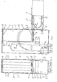
- Fig. 1 einen Vertikalschnitt durch einen Kabelendverschluß mit einem Kassetten-- kasten in Aufbewahrungslage (durchgezogene Linien) und Entnahmelage (strichpunktierte Linien),
- Fig. 2 eine Vorderansicht des Kabelendverschlusses bei abgenommenem Verschlußdeckel,
- Fig. 3 eine Draufsicht auf den Kassettenkasten gemäß Pfeil III in Fig. 1,
- Fig. 4 eine Seitenansicht auf ein mit mehreren übereinander angeordneten Kassettenkästen versehenes Aufteilungsgestell für Glasfaserkabel,
- Fig. 5 einen Horizontalschnitt gemäß der Linie V-V in Fig. 4 in größerem Maßstab,
- Fig. 6 eine Draufsicht auf einen Wickelkörper in Kassettenform,
- Fig. 7 eine Stirnansicht des Wickelkörpers,
- Fig. 8 einen Längsschnitt gemäß der Linie VIII-VIII in Fig. 6,
- Fig. 9 eine perspektivische Detaildarstellung der mit einem Sperrelement verschließbaren Wickelnut des Wickelkörpers,
- Fig. 10 eine Prinzipdarstellung der endständigen Teillängen eines Glasfaserkabels,
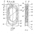
- Fig. 11 eine teilweise geschnittene Draufsicht auf ein weiteres Ausführungsbeispiel eines Wickelkörpers,
- Fig. 12 einen Schnitt gemäß der Linie XII-XII in Fig. 11.
- 1 shows a vertical section through a cable end closure with a cassette box in the storage position (solid lines) and removal position (dash-dotted lines),
- 2 shows a front view of the cable end closure with the closure cover removed,
- 3 is a plan view of the cassette box according to arrow III in Fig. 1,
- 4 shows a side view of a distribution frame for glass fiber cables provided with a plurality of cassette boxes arranged one above the other,
- 5 is a horizontal section along the line VV in Fig. 4 on a larger scale,
- 6 is a plan view of a winding body in cassette form,
- 7 is an end view of the winding body,
- 8 shows a longitudinal section along the line VIII-VIII in FIG. 6,
- 9 is a detailed perspective view of the winding groove of the winding body which can be closed with a locking element,
- 10 shows a basic illustration of the terminal partial lengths of a glass fiber cable,
- 11 is a partially sectioned plan view of a further embodiment of a winding body,
- 12 shows a section along the line XII-XII in FIG. 11.
Die Vorrichtung zur Aufbewahrung der Fasern von Glasfaserkabeln in Verteilereinrichtungen im Fernmeldenetz umfaßt einen Kassettenkasten 1 aus Boden 2, zwei Längsseitenwänden 3, 4 und zwei Stirnwänden 5, 6, welche eine Entnahmeöffnung 7 umschliessen.The device for storing the fibers of fiber optic cables in distribution devices in the telecommunications network comprises a
Der Kassettenkasten 1 ist mittels einer Schiebe-Kipp-Lagerung 8 in einem Gehäuse 9 bzw. in einem Gestell 10 gelagert. Die Schiebe-Kipp-Lagerung 8 ist aus zwei an der Stirnwand 5 des Kassettenkastens 1 nahe der Entnahmeöffnung 7 angeordneten Winkelstücken 11, einer in diesen gelagerten Kippachse 12 und zwei im Gehäuse,9 bzw. Gestell 10 mittels einer Abstandhalterplatte 13'fest angebrachten Führungsschienen 13 gebildet, welche als Schiebelager für die Kippachse 12 dienen und senkrecht zur offenen Seite des Gehäuses 9 bzw. des Gestelles 10 geführt sind und an der offenen Seite enden. Die Führungsschienen 13 weisen je einen Führungsschlitz 14 für die Kippachse 12 auf. Die Führungsschienen 13 sind auf der Abstandhalteplatte 13'befestigt. Diese dient im eingebauten Zustand dazu, eine ausreichende Stabilität der Schiebe-Kipp-Lagerung 8 sicherzustellen und ermöglicht im ausgebauten Zustand des Kassettenkastens 1, daß das Innere des Gehäuses 9 bzw. des Gestells 10 völlig frei zugänglich ist.The
In der ersten Ausführungsform gemäß den Figuren 1 und 2 ist die Verteilereinrichtung ein Kabelendverschluß, welcher aus dem kastenförmigen Gehäuse 9 und einem Verschlußdeckel 15 gebildet ist.In the first embodiment according to FIGS. 1 and 2, the distributor device is a cable end closure, which is formed from the box-
wie die Figur 1 zeigt, ist im Gehäuse 9 ein einziger Kassettenkasten 1 eingesetzt. Dieser befindet sich innerhalb des Gehäuses 9 in seiner Aufbewahrungslage, in welcher der Kassettenkasten 1 gegen einen Anschlag 16 anliegt, der auf der Innenseite der oberen Wandung des Gehäuses 9 befestigt und durch eine Arretierungsfeder 17 gesichert ist, die hinter einer Raste 18 auf der Innenseite der oberen Wandung des Gehäuses 9 einschnappt.1 shows, a
Der Kassettenkasten 1 kann nach dem Abnehmen des Verschlußdeckels 15 und dem Entriegeln der Arretierungsfeder 17 aus dem Gehäuse 9 herausgezogen werden, wobei die Längswände 3, 4 und die Stirnwände 5, 6 des Kassettenkastens 1 parallel zu den jeweiligen Wandungen des Gehäuses 9 herausgeführt werden. Dabei wird die Achse 12 innerhalb der Führungsschlitze 14 der beiden Führungsschienen 13 geführt. Sobald die Kippachse 12 am vorderen Ende der Führungsschlitze 14 angelangt ist, kann der Kassettenkasten 1 um etwa 90° in seine im wesentlichen horizontale Entnahmelage herausgeschwenkt werden, in welcher die Aufnahmeöffnung 7 nach oben gerichtet ist. Dabei bildet die Kippachse 12 ein Kippgelenk. Die Stirnseite 5 des Kassettenkastens 1 schlägt an Anschläge 19 an, welche an der offenen Seite des Gehäuses 9 jeweils auf den Innenseiten der Seitenwandungen fest angebracht sind.The
In dem Kassettenkasten 1 sind gemäß Fig. 3 fünf Kassetten 20 für das bewegliche Zuführungskabel des Glasfaserkabels 23 nebeneinander angeordnet, welche jeweils Wickelkörper 59 für das Glasfaserkabel 23 und Spleißkassetten 59 für die Spleißreserve 52 des Glasfaserkabels 23 beinhalten. Die über Kabeleinführungen 22 des Gehäuses 9 zugeführten Glasfaserkabel 23 sind in der Entnahmelage des Kassettenkastens 1 bogenförmig den einzelnen, im Kassettenkasten 1 angeordneten, mit Spleißkassetten 58 versehenen Wickelkörpern 59 zugeführt. In der in Fig. 1 ebenfalls dargestellten vertikalen Aufbewahrungslage des Kassettenkastens 1 verlaufen die Glasfaserkabel 23 immer noch, den Wickelradius R des Wickelkörpers 59 ausnutzend, bogenförmig von den Kabeleinführungen 22 zu den Wickelkörpern 59 innerhalb des Kassettenkastens 1. Somit sind die Glasfaserkabel 23 sowohl in der Aufbewahrungslage des Kassettenkastens 1 im Gehäuse 9 als auch in der Entnahmelage des Kassettenkastens 1 unter Ausnutzung des zulässigen Biegeradius bruchsicher aufbewahrt.3, five
Zur Aufnahme von Rangierfasern 24 ist auf der Entnahmeöffnung 7 des Kassettenkastens 1 eine Einrichtung 25 zur Befestigung einer Tasche 26 zum knickfreien raumsparenden Verstauen der Rangierfasern 24 innerhalb des Kassettenkastens 1 vorgesehen. Die Einrichtung 25 umfaßt einen die Entnahmeöffnung 7 überspannenden Riegel 27 zur Befestigung der Tasche 26 mittels druckknopfartiger Befestigungselemente 29, welcher sich auf den im Kassettenkasten 1 befindlichen Kassetten-20 abstützt und gleichzeitig das Herausfallen der Kassetten 20 verhindert. Die Tasche 26 *nimmt die innerhalb des Kassettenkastens 1 rangierten Rangierfasern 24 auf und ermöglicht den Ausgleich der ungenauen Zuführungslänge der Rangierfasern 24 mittels frei wählbarer Befestigungslöcher 43.To accommodate shunting
In der in den-Figuren 4 und 5 dargestellten zweiten Ausführungsform sind in einem Aufteilungsgestell 10 für Glaserfaserkabel 23 mehrere Kassettenkästen 1 übereinander angeordnet. Jeder Kassettenkasten 1 ist mittels einer Schiebe-Kipp-Lagerung 8, welche analog der in den Figuren 1 und 2 dargestellten ersten Ausführungsform ausgbildet ist, auf je einer Befestigungskonsole 30 gelagert, welche wiederum mit dem Gestell 10 fest verbunden sind.In the second embodiment shown in FIGS. 4 and 5, a plurality of
Auf diese Weise können die Kassettenkästen 1 gemäß der in den Figuren 4 und 5 dargestellten zweiten Ausführungsform in gleicher Weise aus ihrer im wesentlichen vertikalen Aufbewahrungslage in ihre im wesentlichen horizontale Entnahmelage mit obenliegender Entnahmeöffnung 7 bewegt werden, wie es bei der ersten Ausführungsform gemäß Fig. 1 und 2 näher beschrieben worden ist.In this way, the
Das im horizontalen Querschnitt etwa U-förmige Gestell 10 trägt oberhalb jeder an diesem befestigten Befestigungskonsole 30 etwa halbkreisförmig ausgebildete Leitkörper 31 für Rangierfasern 24; welche die in den einzelnen Kassettenkästen 1 befindlichen, auf den Wickelkörpern 59 der Kassetten 2 aufgewickelten Glasfasern 23 miteinander verbinden.The approximately
Die Leitkörper 31 sind auf der Innenseite des Gestells 10 zwischen diesem und den in der Aufbewahrungslage befindlichen Kassettenkästen 1 angeordnet. Zum Einziehen der Rangierfasern 24 ist auf der Innenseite des U-förmigen Gestells 10 ein Transportaufzug 32 gelagert, der hinter den in ihrer vertikalen Aufbewahrungslage befindlichen Kassettenkästen 1 sowie hinter den Leitkörpern 31 verläuft. Der Transportaufzug 32 für die Rangierfasern 24 ist aus am oberen und unteren Ende des Gestells 10 gelagerten Umlenkrollen 33 und einem um diesen herumgeführten Transportseil 34 gebildet, mit welchem eine Transportklammer 35 für eine oder mehrere_Rangierfasern 24 lösbar verbindbar ist.The
Zur Festlegung der Transportklammer 35 am Transpoportseil 34 ist dieses mit einer aufgequetschten Hülse 36 versehen, auf welche die Transportklammer 35 mit ihrer Klemmstelle 37 aufgeklemmt ist. Parallel hierzu und auf der dem Drehpunkt 38 der Transportklammer 35 abgewandten Seite ist ein Führungskanal 39 für das andere Trum des Transportseiles 34 ausgebildet. Auf einer Seite trägt die Transportklammer 35 eine Klemme 40 zum Einklemmen einer oder mehrerer Rangierfasern 24. Mittels des Transportaufzuges 32 können Rangierfasern 24 in einfacher Weise innerhalb des Gestells 10 von einem Kassettenkasten 1 zum anderen Kassettenkasten 1 verlegt werden, ohne die dazwischenliegenden Kassettenkästen 1 zu öffnen bzw. auszubauen. Die Transportklammer 35 ist frei mit dem Transportseil 34 verbindbar und kann zur Befestigung einer oder mehrerer Rangierfasern 24 aus dem Gestell 10 entnommen werden.To fix the
Die Fig. 5 zeigt im horizontalen Querschnitt die Führung mehrerer Glasfaserkabel 23 und Rangierfasern 24. Zur Führung der Glasfaserkabel 23 sind auf der Rückseite des Gestells 10 Führungsrohre 41 unterschiedlicher Länge angebracht, deren Austrittsöffnung 42 jeweils einem Kassettenkasten 1 zugeordnet ist.5 shows, in horizontal cross section, the guidance of a plurality of
Zum leichten Einbringen der Glasfaserkabel 23 in das Gestell 10 ist die Schiebe-Kipp-Lagerung 8 demontierbar sowohl im Gehäuse 9 als auch im Gestell 10 gelagert. Die leichte Demontierbarkeit wird dadurch erzielt, daß der Kassettenkasten 1 mit der Führungsschiene 13 mittels Schraubverbindungen 28 an den Seitenwänden des Gehäuserahmens 9 bzw. an den Befestigungskonsolen 30 leicht lösbar befestigt ist.For easy insertion of the
Bei der vorangehend beschriebenen Verteilereinrichtung im Fernmeldenetz mit Glasfaserkabeln 23 werden die Glasfasern 52 der auf einer Spleißkassette 58 aufgenommenen Spleißreserve außerhalb der Verteilergehäuse 9 oder -gestelle 10 auf einem nicht dargestellten Spleißtisch gespleißt, wobei die Spleißstelle selbst nicht wiederverwendbar ist, da bei jedem wiederholten Spleiß ca. 30 mm der Glasfaser 52 verlorengeht.' In the previously described distribution device in the telecommunications network with
Dies führt dazu, daß in der Verteilereinrichtung bis zur am Ende der Glasfaser 52 gelegenen Spleißstelle zusätzliche Teillängen der Glasfaserkabel 23 beweglich untergebracht werden müssen (Fig. 10). Diese beweglichen Teillängen der Glasfaserkabel 23 sind das interne Verteilerkabel 53, welches zwischen einer Kabelbefestigung 54 am Anfang des Gestelles 10 und einer Kabelbefestigung 55 im Gestell 10 liegt, und ferner das bewegliche Zuführungskabel 21, das zwischen der Kabelbefestigung 55 im Gestell 10 und dem Anfangspunkt 57 der Glasfasern 52 der auf die Spleißkassette 58 aufgewickelten,beweglichen Spleißreserve angeordnet ist.This leads to the fact that additional partial lengths of the
Die Glasfasern 52 der beweglichen Spleißreserve haben eine Länge von etwa 1 m. Zur Aufnahme des beweglichen Zuführungskabels 21 von etwa 1 bis 2 m Länge, insbesondere 1,5 m, ist der nachstehend beschriebene Wickelkörper 59 vorgesehen, der zusammen mit den auf die Spleißkassette 58 aufgewickelten Glasfasern 52 der beweglichen Spleißreserve nahe der Kabelbefestigung 55 gelagert ist und nur zum Spleißen der Glasfasern 52 der beweglichen Spleißreserve aus dem Kassettenkasten 1 entnommen wird.The
Unter Glasfasern 52 werden sowohl einzelne Glasfasern als auch Bündel von Glasfasern verstanden. Das bewegliche Zuführungskabel 21 kann sowohl aus einem einzelnen Glasfaserkabel 23 als auch aus mehreren Glasfaserkabeln 23 gebildet sein. Auch können die Rangierfasern 24 parallel zu den Zuführungskabeln 21 geführt sein.
Der flache und scheibenförmige Wickelkörper 59 umfaßt einen Wickelraum 60, der von zwei Seitenwänden 61, 62 begrenzt wird, welche eine dazwischen befindliche Wickelscheibe 63 von kleineren Flächenabmessungen als die Seitenwände 61, 62 umschließen.The flat and disk-shaped winding
Die Wickelscheibe 63 ist am oberen und unteren Ende des Wickelkörpers 59 unter einem Radius R abgerundet, der größer als 30 mm ist, um ein Knicken der Glasfasern 52 des Zuführungskabels 21 und ggf. der Rangierfasern 24 zu vermeiden. Der zwischen den beiden Seitenwänden 61 und 62 und dem Umfang der Wickelscheibe 63 befindliche Wickelraum 60 bildet eine Wickelnut 64 für das bewegliche Zuführungskabel 21, so daß die Wickelnut 64 zur Aufnahme der notwendigen Länge des Zuführungskabels 21 des Glasfaserkabels 23 und ggf. der Rangierfasern 24 ausreichend dimensioniert werden kann.The winding
Auf der Außenseite der Seitenwand 62 des Wickelkörpers 59 ist eine Aufnahme 65 für die Spleißkassette 58 vorgesehen. Die Aufnahme 65 für die Spleißkassette 58 ist aus auf den Rändern der Seitenwand 62 des Wickelkörpers 59 angeordneten Stegen 66 bis 68 gebildet, deren Höhe über die Seitenwand 62 etwa der Dicke einer Spleißkassette 59 entspricht, deren Standarddicke 8 mm beträgt. Die Spleißkassette 58 wird zwischen die Innenstege 66 bis 68 hinter am Steg 67 angebrachten, nach innen ragenden Haken 57 eingelegt und an der dem Steg 67 gegenüberliegenden freien Seite der Aufnahme 65 mittels eines Riegels 69 lösbar in der Aufnahme 65 arretiert, wie es insbesondere Fig. 6 zeigt, in welcher die Spleißkassette 59 mit gestrichelten Linien eingezeichnet ist.A
Anstelle der Spleißkassette 58 können auch bei entsprechender Ausbildung der Stege 66 bis 68 die Glasfasern 52 der Spleißreserve unmittelbar in der Aufnahme 65 gelagert werden.Instead of the
Die über die Aufnahme 65 hinausragende Fläche der Seitenwand 62 des Wickelkörpers 59 ist mit von stegartigen Rändern 70, 71 begrenzten Führungskanälen 70, 71 versehen, welche in einem Führungskanal 72 zusammengeführt sind, der zur Überführung des Zuführungskabels 21 aus der Ebene der Aufnahme 65 in die Ebene des parallel hierzu umlaufenden Wickelraumes 60 dient, welcher durch die Wickelnut 64 zwischen den beiden Seitenwänden 61, 62 gebildet ist.The surface of the
Der überführende Führungskanal 72 weist in der Ebene der Seitenwand 62 in Richtung der Wickelnut 64 offene Stufen 72 auf, welche einen tangentialen Anschluß der Führungskanäle 70 bis 72 an den Außenumfang der Wickel Scheibe 63 bilden, wie es insbesondere aus den Figuren 6 und 8 ersichtlich ist. Der Führungskanal 72 ist bis zum äußeren Umfang der Seitenwand 62 freigeschnitten, um ein seitliches Einführen des Zuführungskabels 56 aus den Führungskanälen 70, 71 auf der Oberseite der Seitenwand 62 und somit aus der Aufnahme 65 in die Wickelnut 64 zu ermöglichen. Der Randbereich der Seitenwand 62 oberhalb der Aufnahme 65 und der Führungskanäle 70, 71 ist noch mit einem umlaufenden Versteifungssteg 66 versehen.The transferring
In den Seitenwänden 61, 62 der Wickelnut 64 sind an mehreren Stellen gegenüberliegende Schlitze 73, 74 vorgesehen, welche L-förmig in das Material der Seitenwände 61, 62 eingelassen sind und in welche Rastnoppen 75 von Sperrelementen 76 einrastbar sind, um ein ungewolltes Hinausbewegen des in der Wickelnut 64 aufgewickelten Zuführungskabels 56 aus der Wickelnut 64 zu verhindern.In the
Die Sperrelemente 76 drücken beim Eindrücken der Rastnoppen 75 in die Schlitze 73, 74 die von diesen freigeschnittenen Wandungsteile 77 der Seitenwände 61, 62 federnd zurück, wodurch die Rastnoppen 75 federnd in den hinter den Wandungsteilen 77 ausgeformten Mulden 77 einrasten. Im Bereich der Schlitze 73 sind die Stege 66, 67, 68 mit Ausschnitten 78 versehen.When the locking knobs 75 are pressed into the
Der Wickelkörper 59 ist mit den Seitenwänden '61, 62 der Wickelscheibe 63 und den Stegen '66, 66', 67 und 68 sowie den Begrenzungsstegen 70,70', 71' der Führungskanäle 70, 71, 72 so ausgelegt, daß dieser z. B. einstückig aus Kunststoff gefertigt werden kann.The winding
Das in den Figuren 11 und 12 dargestellte weitere Ausführungsbeispiel umfaßt einen Wickelkörper 81 aus zwei parallelen, im wesentlichen rechteckigen Seitenwänden 82, 83, welche den Wickelkörper 81 nach außen begrenzen. Jede Seitenwand 82, 83 weist auf einer Hälfte ihrer Innenseite Führungsstege 84, 85 auf, die einen Führungskanal 86 zwischen sich einschließen. Der Führungssteg 84 entspricht dem halben Umfang eines länglichen Ovals, wobei das in Fig. 11 unten dargestellte Ende des Führungssteges 84 dicker ist als das in Fig. 11 oben dargestellte andere Ende des Führungssteges 84. Diesem dünneren Ende des Führungssteges 84 liegt, getrennt durch den Führungskanal 86, der leitschaufelartig ausgebildete Führungssteg 85 gegenüber. In entsprechender Weise sind die Führungsstege 84' und 85' der anderen Seitenwand 83 ausgebildet, welche Führungsstege 84', 85'den Führungskanal 86' einschließen.The further exemplary embodiment shown in FIGS. 11 and 12 comprises a winding
Dieser liegt diametral dem Führungskanal 86 der Seitenwand 82 gegenüber.This is diametrically opposite the
Durch sandwichartiges Übereinanderlegen der beiden Seitenwände 82, 83 schließen sich die länglich oval ausgebildeten Führungsstege 84, 85 und 84', 85' zu einer Wickelscheibe mit einer äußeren Wickelnut 87 und mit einem inneren Aufnahmeraum 88. Der innere Aufnahmeraum 88 ist zur Aufnahme einer oder mehrerer beutelartiger Taschen 89 vorgesehen, welche mittels Ringösen 90 zusammengefaßt sind. In den beutelartigen Taschen 89 befinden sich die Glasfasern 52 der beweglichen Spleißreserve eines Glasfaserkabels 23, dessen bewegliches Zuführungskabel 21 in der Wickelnut 87 aufgewickelt ist. Die Überführung des beweglichen Zuführungskabels 56 aus der Wickelnut 87 in die Aufnahme 88 erfolgt durch den Führungskanal 86 der Seitenwand 82.By sandwiching the two
Bei der Handhabung des Wickelkörpers 81 werden zunächst die beutelartigen Taschen 89 mit den Glasfasern 52 der beweglichen Spleißreserve in den die Aufnahme 88 bildenden Innenraum zwischen den Führungsstegen 84, 85 eingelegt, wobei das bewegliche Zuführungskabel 56 durch den zugehörigen Führungskanal 86 geführt wird. Anschließend wird die andere, spiegelbildlich ausgebildete Seitenwand 83 aufgelegt, so daß nach Vervollständigung der Wickelnut 87 das bewegliche Zuführungskabel 21 in die Wickelnut 87 eingelegt bzw. eingewickelt werden kann.
Jede der beiden Seitenwände 82, 83 mit zugeordneten Führungsstegen 84, 85 bzw. 84', 85' kann einstückig aus Kunststoff hergestellt sein. Zur gegenseitigen Fixierung sind auf den Führungsstegen 85, 85' Rastnocken 91 vorgesehen, welche in entsprechend ausgebildete Rastöffnungen der gegenüberliegenden Seitenwände 82, 83 eingedrückt werden.When handling the winding
Each of the two
Claims (10)
dadurch gekennzeichnet, daß im Gehäuse (9,10) mindestens ein mit einer Entnahme-Öffnung (7) versehener Kassettenkasten (1) zur Aufnahme einer Kassette (20) vorgesehen ist und daß der Kassettenkasten (1) aus seiner im wesentlichen vertikalen Aufbewahrungslage im Gehäuse (9,10) in seine im wesentlichen horizontale Entnahmelage mit oben liegender Entnahme-Öffnung (7) bewegbar ist.1. Device for storing the fibers of fiber optic cables in distribution devices in the telecommunications network, from a housing for receiving at least one cassette provided with a winding body and removable from the housing for removing the fibers for fiber supply lengths,
characterized in that in the housing (9, 10) there is at least one cassette box (1) provided with a removal opening (7) for receiving a cassette (20) and in that the cassette box (1) from its essentially vertical storage position in the housing (9, 10) can be moved into its essentially horizontal removal position with the removal opening (7) at the top.
dadurch gekennzeichnet,
daß der Kassettenkasten (1) im Gehäuse (9,10) mittels einer Schiebe-Kipp-Lagerung (8) gelagert ist, die aus einer, mittels zweier an einer Stirnwand (5) des Kassettenkastens (1) nahe der Entnahme-Öffnung (7) angeordneter Winkelstücke (11) gelagerten Kippachse (12) und aus zwei im Gehäuse (9,10) fest angebrachten, mit Führungsschlitzen (14) versehenen Führungsschienen (13) gebildet ist, welche als Schiebelager für die Kippachse (12) dienen und senkrecht zur offenen Seite des Gehäuses (9,10) geführt sind und an dessen offener Seite enden.2. Device according to claim 1,
characterized,
that the cassette box (1) is mounted in the housing (9, 10) by means of a slide-tilt bearing (8), which consists of one, by means of two on an end wall (5) of the cassette box (1) near the removal opening (7 ) arranged angle pieces (11) mounted tilt axis (12) and from two in the housing (9,10) fixed, with guide slots (14) provided with guide rails (13), which serve as sliding bearings for the tilt axis (12) and perpendicular to open side of the housing (9,10) are guided and end on the open side.
daß die Wickelnut (64) mit einer Wickelscheibe (63) versehen ist, die in der Ebene parallel zur Aufnahme (65) mit einem Radius (R) ausgebildet ist, der größer als 30 mm ist.6. The device according to claim 5, characterized in that
that the winding groove (64) is provided with a winding disc (63) which is formed in the plane parallel to the receptacle (65) with a radius (R) which is greater than 30 mm.
daß die Aufnahme (65) aus auf den Rändern der Seitenwand (62) des Wickelkörpers (59) angeordneten Stegen (66 bis 68) gebildet ist, deren Höhe (H) über der Oberfläche der Seitenwand (62) etwa der Dicke (D) einer Spleißkassette (58) entspricht.7. Device according to one of claims 4 to 6, characterized in that
that the receptacle (65) is formed from webs (66 to 68) arranged on the edges of the side wall (62) of the winding former (59), the height (H) of which is about the thickness (D) above the surface of the side wall (62) Splice cassette (58) corresponds.
daß die Spleißkassette (58) zwischen den Stegen (66, 67,68) der Aufnahme (65) eingehängt ist.8. The device according to claim 7, characterized in that
that the splice cassette (58) is suspended between the webs (66, 67, 68) of the receptacle (65).
daß die Länge (L) des Wickelkörpers (59) größer ist als die Länge (I) der Aufnahme (65) und daß auf der die Aufnahme (65) für die Spleißkassette (58) bildenden Seitenwand (62) des Wickelkörpers (59) außerhalb der Aufnahme (65) mindestens ein Überführungskanal (72) für das Zuführungskabel (56) ausgebildet ist, durch welchen hindurch das Zuführungskabel (56) von der die Aufnahme (65) ausbildenden Außenseite der Seitenwand (62) auf die Wickelscheibe (63) der Wickelnut (64) geführt ist.9. Device according to one of claims 4 to 8, characterized in
that the length (L) of the winding body (59) is greater than the length (I) of the receptacle (65) and that on the side wall (62) of the winding body (59) forming the receptacle (65) for the splice cassette (58) outside the receptacle (65) is formed with at least one transfer channel (72) for the feed cable (56), through which the feed cable (56) passes from the outside of the side wall (62) forming the receptacle (65) to the winding disk (63) of the winding groove (64) is performed.
daß der Wickelkörper (59) aus zwei sandwichartig übereinanderliegenden Seitenwänden (82, 83) gebildet ist, die spiegelbildlich mit länglich oval ausgebildeten Führungsstegen (84, 85) versehen sind, welche zwischen sich die Führungskanäle (86) für das bewegliche Zuführungskabel (56) einschließen, und daß innerhalb des von den ovalen Führungsstegen (84, 85) eingeschlossenen Aufnahmeraumes (78) beutelartige Taschen (89) für Glasfasern (52) der beweglichen Spleißreserve des Glasfaserkabels (51) angeordnet sind.10. Device according to one of claims 1 to 9, characterized in
that the winding body (59) is formed from two sandwich-like superimposed side walls (82, 83), which are provided in mirror image with elongated oval guide webs (84, 85) which enclose between them the guide channels (86) for the movable feed cable (56) , and that inside the receiving space (78) enclosed by the oval guide webs (84, 85), bag-like pockets (89) for glass fibers (52) of the movable splice reserve of the fiber optic cable (51) are arranged.
Priority Applications (1)
| Application Number | Priority Date | Filing Date | Title |
|---|---|---|---|
| AT86730176T ATE65615T1 (en) | 1985-11-12 | 1986-10-25 | DEVICE FOR STORING THE FIBERS OF FIBER OPTIC CABLES IN DISTRIBUTION EQUIPMENT IN THE TELECOMMUNICATION NETWORK. |
Applications Claiming Priority (4)
| Application Number | Priority Date | Filing Date | Title |
|---|---|---|---|
| DE3540473 | 1985-11-12 | ||
| DE19853540473 DE3540473A1 (en) | 1985-11-12 | 1985-11-12 | Device for storing a feed cable as sub-length of an optical fibre cable, in particular for distribution devices in the telecommunications network |
| DE3540472 | 1985-11-12 | ||
| DE19853540472 DE3540472A1 (en) | 1985-11-12 | 1985-11-12 | Device for storing fibres of optical fibre cables in distribution devices in the telecommunication network |
Publications (3)
| Publication Number | Publication Date |
|---|---|
| EP0222691A2 true EP0222691A2 (en) | 1987-05-20 |
| EP0222691A3 EP0222691A3 (en) | 1989-08-09 |
| EP0222691B1 EP0222691B1 (en) | 1991-07-24 |
Family
ID=25837859
Family Applications (1)
| Application Number | Title | Priority Date | Filing Date |
|---|---|---|---|
| EP86730176A Expired - Lifetime EP0222691B1 (en) | 1985-11-12 | 1986-10-25 | Device for the preservation of the fibres of glass fibre cables in the distribution assemblies of a telecommunication network |
Country Status (4)
| Country | Link |
|---|---|
| US (1) | US4770357A (en) |
| EP (1) | EP0222691B1 (en) |
| AU (1) | AU6508586A (en) |
| DE (1) | DE3680465D1 (en) |
Cited By (8)
| Publication number | Priority date | Publication date | Assignee | Title |
|---|---|---|---|---|
| EP0397587A1 (en) * | 1989-05-11 | 1990-11-14 | France Telecom | Module and optical fiber cables connecting-box |
| EP0585658A1 (en) * | 1992-09-04 | 1994-03-09 | KRONE Aktiengesellschaft | Device for the preservation of fibres and bundles of fiber optique cables in distribution assemblies of telecommunication and data networks |
| DE4322142A1 (en) * | 1993-07-02 | 1995-01-12 | Siemens Ag | Cable-storage module for optical waveguides |
| WO1997019377A1 (en) * | 1995-11-22 | 1997-05-29 | Bowthorpe Plc | Splice arrangements for optical fibre cables |
| AT2443U1 (en) * | 1997-11-18 | 1998-10-27 | Felten & Guilleaume Ag Oester | DISTRIBUTION BOX FOR LIGHTWAVE GUIDES |
| GB2368138A (en) * | 2000-10-17 | 2002-04-24 | Spirent Plc | Splice storage apparatus with peripheral store for optic fibre |
| GB2368139A (en) * | 2000-10-17 | 2002-04-24 | Spirent Plc | Optic fibre splice storage tray stack |
| EP1231492A1 (en) * | 2001-02-13 | 2002-08-14 | Colt Telecom AG | Demountable boxes for telecommunications and data-technical lightwave networks |
Families Citing this family (26)
| Publication number | Priority date | Publication date | Assignee | Title |
|---|---|---|---|---|
| US4824196A (en) * | 1987-05-26 | 1989-04-25 | Minnesota Mining And Manufacturing Company | Optical fiber distribution panel |
| US4986626A (en) * | 1989-08-15 | 1991-01-22 | Minnesota Mining And Manufacturing Company | Optical fiber termination module |
| US5052775A (en) * | 1989-08-15 | 1991-10-01 | Minnesota Mining And Manufacturing Company | Optical fiber module termination array and panel |
| US5100221A (en) * | 1990-01-22 | 1992-03-31 | Porta Systems Corp. | Optical fiber cable distribution frame and support |
| US5142606A (en) * | 1990-01-22 | 1992-08-25 | Porta Systems Corp. | Optical fiber cable distribution frame and support |
| WO1991018311A2 (en) * | 1990-05-21 | 1991-11-28 | Minnesota Mining And Manufacturing Company | Optical fiber distribution center |
| DE4106171A1 (en) * | 1991-02-27 | 1992-09-03 | Siemens Ag | CASSETTE AND CASSETTE BLOCK FOR LIGHTWAVE GUIDE |
| US5187766A (en) * | 1991-02-27 | 1993-02-16 | Siemens Aktiengesellschaft | Optical fiber waveguide division rack for holding plural cassettes |
| US5339379A (en) * | 1993-06-18 | 1994-08-16 | Telect, Inc. | Telecommunication fiber optic cable distribution apparatus |
| US5469526A (en) * | 1994-01-07 | 1995-11-21 | Porta Systems Corp. | Optical fiber support for printed circuit boards |
| EP0801317B1 (en) * | 1996-04-12 | 2002-06-26 | Telephone Cables Limited | Management of optical fibre |
| JP2852281B2 (en) * | 1996-11-22 | 1999-01-27 | 住友電気工業株式会社 | Attachment part of optical cable storage case to communication device housing |
| FR2757644A1 (en) * | 1996-12-24 | 1998-06-26 | Proptic | Distribution box for providing end connections on distribution optical fibre cable |
| US5758002A (en) * | 1996-12-31 | 1998-05-26 | Siecor Corporation | Routing and storage apparatus for optical fibers |
| US5913006A (en) * | 1997-11-25 | 1999-06-15 | Northern Telecom Limited | Fibre slack storage retractable panel and interface |
| US6215938B1 (en) * | 1998-09-21 | 2001-04-10 | Adc Telecommunications, Inc. | Fiber optic cabinet and tray |
| US6571046B1 (en) * | 1999-09-23 | 2003-05-27 | Baker Hughes Incorporated | Protector system for fiber optic system components in subsurface applications |
| US6788869B2 (en) * | 2001-01-30 | 2004-09-07 | William Strausbaugh | Method for packaging passive optoelectric assemblies in a limited space |
| US20060264252A1 (en) * | 2005-05-23 | 2006-11-23 | White Gehrig H | System and method for providing a host console for use with an electronic card game |
| US7382961B2 (en) | 2006-05-23 | 2008-06-03 | Telect Inc. | Fiber transitioning |
| JP5245240B2 (en) * | 2006-10-26 | 2013-07-24 | 住友電気工業株式会社 | Optical fiber coil storage container and optical fiber module |
| EP2450728A1 (en) * | 2010-11-05 | 2012-05-09 | British Telecommunications Public Limited Company | Optical fibre tray |
| EP2610188B1 (en) * | 2011-12-30 | 2017-12-27 | Krones AG | Labelling unit |
| US9606315B2 (en) | 2013-03-15 | 2017-03-28 | All Systems Broadband, Inc. | Optical fiber ribbon storage |
| RU2583998C1 (en) * | 2015-01-20 | 2016-05-20 | Борис Алексеевич Хозяинов | Device for installation of switching cords in telecommunication rack (box) |
| EP3698191A4 (en) | 2017-10-17 | 2021-09-29 | Corning Research & Development Corporation | Cable retention couplers and related methods |
Citations (3)
| Publication number | Priority date | Publication date | Assignee | Title |
|---|---|---|---|---|
| EP0101970A1 (en) * | 1982-08-04 | 1984-03-07 | Alcatel | Optical cable head |
| EP0146478A2 (en) * | 1983-12-20 | 1985-06-26 | Lignes Telegraphiques Et Telephoniques L.T.T. | Joining apparatus for cables, especially optical fibres |
| FR2559916A1 (en) * | 1984-02-21 | 1985-08-23 | Constr Telephoniques | Method, used in the connecting of optical fibres, for making and storing a length of fibre in reserve, and device relating to it. |
Family Cites Families (8)
| Publication number | Priority date | Publication date | Assignee | Title |
|---|---|---|---|---|
| US3494622A (en) * | 1968-09-23 | 1970-02-10 | Robert C Zeigler Jr | Tape cartridge storage apparatus |
| US3715040A (en) * | 1970-07-14 | 1973-02-06 | Advanced Digital Syst Inc | Data accessing system |
| US4217030A (en) * | 1978-07-18 | 1980-08-12 | Bell Telephone Laboratories, Incorporated | Fiberoptic-electronic connector assembly |
| US4266853A (en) * | 1979-03-12 | 1981-05-12 | Northern Telecom Limited | Device for organizing optical fibers and the like |
| US4319951A (en) * | 1980-04-29 | 1982-03-16 | Gk Technologies, Incorporated | Fiber organizer for splice cases and terminals |
| US4428645A (en) * | 1981-01-28 | 1984-01-31 | Gk Technologies, Incorporated | Cable accumulator |
| DE3236213A1 (en) * | 1982-09-30 | 1984-04-12 | ANT Nachrichtentechnik GmbH, 7150 Backnang | Holder for protective sheaths for accommodating spare lengths of fibre-optic waveguide |
| US4609161A (en) * | 1985-01-30 | 1986-09-02 | The Firestone Tire & Rubber Company | System and apparatus for storing and processing strip material |
-
1986
- 1986-10-25 EP EP86730176A patent/EP0222691B1/en not_active Expired - Lifetime
- 1986-10-25 DE DE8686730176T patent/DE3680465D1/en not_active Expired - Fee Related
- 1986-11-12 AU AU65085/86A patent/AU6508586A/en not_active Abandoned
- 1986-12-22 US US06/945,350 patent/US4770357A/en not_active Expired - Fee Related
Patent Citations (3)
| Publication number | Priority date | Publication date | Assignee | Title |
|---|---|---|---|---|
| EP0101970A1 (en) * | 1982-08-04 | 1984-03-07 | Alcatel | Optical cable head |
| EP0146478A2 (en) * | 1983-12-20 | 1985-06-26 | Lignes Telegraphiques Et Telephoniques L.T.T. | Joining apparatus for cables, especially optical fibres |
| FR2559916A1 (en) * | 1984-02-21 | 1985-08-23 | Constr Telephoniques | Method, used in the connecting of optical fibres, for making and storing a length of fibre in reserve, and device relating to it. |
Cited By (10)
| Publication number | Priority date | Publication date | Assignee | Title |
|---|---|---|---|---|
| EP0397587A1 (en) * | 1989-05-11 | 1990-11-14 | France Telecom | Module and optical fiber cables connecting-box |
| FR2646928A1 (en) * | 1989-05-11 | 1990-11-16 | France Etat | MODULE AND BOX FOR CONNECTING FIBER OPTIC CABLES |
| EP0585658A1 (en) * | 1992-09-04 | 1994-03-09 | KRONE Aktiengesellschaft | Device for the preservation of fibres and bundles of fiber optique cables in distribution assemblies of telecommunication and data networks |
| US5421532A (en) * | 1992-09-04 | 1995-06-06 | Krone Aktiengesellschaft | Device for storing the single and bundle wires of glass-fiber cables in distributor devices used in telecommunication and data transfer applications |
| DE4322142A1 (en) * | 1993-07-02 | 1995-01-12 | Siemens Ag | Cable-storage module for optical waveguides |
| WO1997019377A1 (en) * | 1995-11-22 | 1997-05-29 | Bowthorpe Plc | Splice arrangements for optical fibre cables |
| AT2443U1 (en) * | 1997-11-18 | 1998-10-27 | Felten & Guilleaume Ag Oester | DISTRIBUTION BOX FOR LIGHTWAVE GUIDES |
| GB2368138A (en) * | 2000-10-17 | 2002-04-24 | Spirent Plc | Splice storage apparatus with peripheral store for optic fibre |
| GB2368139A (en) * | 2000-10-17 | 2002-04-24 | Spirent Plc | Optic fibre splice storage tray stack |
| EP1231492A1 (en) * | 2001-02-13 | 2002-08-14 | Colt Telecom AG | Demountable boxes for telecommunications and data-technical lightwave networks |
Also Published As
| Publication number | Publication date |
|---|---|
| AU6508586A (en) | 1987-05-14 |
| US4770357A (en) | 1988-09-13 |
| EP0222691A3 (en) | 1989-08-09 |
| DE3680465D1 (en) | 1991-08-29 |
| EP0222691B1 (en) | 1991-07-24 |
Similar Documents
| Publication | Publication Date | Title |
|---|---|---|
| EP0222691B1 (en) | Device for the preservation of the fibres of glass fibre cables in the distribution assemblies of a telecommunication network | |
| DE4229884C2 (en) | Device for storing the single and loose tubes of fiber optic cables in distribution facilities for telecommunications and data technology | |
| DE3640836C1 (en) | Splice cassette housing for optical fibers | |
| EP1567902B1 (en) | Device for the structured storage or handling of optical waveguides | |
| EP0281196B1 (en) | Storing device for the supply length of at least one light wave guide | |
| WO2007118585A1 (en) | Dividing device and handling device for optical waveguides | |
| EP2290418B1 (en) | Device for storage and handling of lightguides | |
| EP0872750A2 (en) | Junction box with a holding device for cassettes for storing optical fibres and their splices | |
| EP0579019B1 (en) | Optical fibre splice cassette lay device for cable coupling box | |
| DE2510605A1 (en) | TAPE CASSETTE | |
| DE3706518A1 (en) | Method and arrangement for winding by means of a winding cassette the excess lengths of optical waveguides which are connected to one another | |
| DE3540472C2 (en) | ||
| DE102007032186A1 (en) | Support system for fastening fiber optic telecommunications and data equipment, includes profile terminated by specially-shaped U- and V-sections at its ends | |
| EP1921479A1 (en) | Device for the structured storage or handling of optical waveguides | |
| EP2132589B1 (en) | Sleeve for optical waveguide cables | |
| DE3540473C2 (en) | ||
| DE3033928C1 (en) | Optical fiber with a stackable storage element | |
| AT397331B (en) | FRAME FOR TELECOMMUNICATION DEVICES | |
| WO2004021061A1 (en) | Splice cassette management system | |
| DE3217320C2 (en) | Cable fitting to accommodate fiber optic splices | |
| DE4417767C2 (en) | Arrangement for splicing and stocking optical fibers | |
| EP0579899A1 (en) | Connection device for a glass fibre cable | |
| WO2001055754A2 (en) | Sleeve insert and sleeve for guiding optical waveguide elements and for accommodating a splicing device | |
| DE102020114225B3 (en) | Fiber guide module and organizer system | |
| DE102020107026B4 (en) | Cassette and cassette assembly |
Legal Events
| Date | Code | Title | Description |
|---|---|---|---|
| PUAI | Public reference made under article 153(3) epc to a published international application that has entered the european phase |
Free format text: ORIGINAL CODE: 0009012 |
|
| AK | Designated contracting states |
Kind code of ref document: A2 Designated state(s): AT BE CH DE ES FR GB GR IT LI LU NL SE |
|
| PUAL | Search report despatched |
Free format text: ORIGINAL CODE: 0009013 |
|
| AK | Designated contracting states |
Kind code of ref document: A3 Designated state(s): AT BE CH DE ES FR GB GR IT LI LU NL SE |
|
| 17P | Request for examination filed |
Effective date: 19890628 |
|
| 17Q | First examination report despatched |
Effective date: 19900228 |
|
| GRAA | (expected) grant |
Free format text: ORIGINAL CODE: 0009210 |
|
| AK | Designated contracting states |
Kind code of ref document: B1 Designated state(s): AT BE CH DE ES FR GB GR IT LI LU NL SE |
|
| PG25 | Lapsed in a contracting state [announced via postgrant information from national office to epo] |
Ref country code: IT Free format text: LAPSE BECAUSE OF FAILURE TO SUBMIT A TRANSLATION OF THE DESCRIPTION OR TO PAY THE FEE WITHIN THE PRE;WARNING: LAPSES OF ITALIAN PATENTS WITH EFFECTIVE DATE BEFORE 2007 MAY HAVE OCCURRED AT ANY TIME BEFORE 2007. THE CORRECT EFFECTIVE DATE MAY BE DIFFERENT FROM THE ONE RECORDED.SCRIBED TIME-LIMIT Effective date: 19910724 Ref country code: NL Effective date: 19910724 Ref country code: SE Effective date: 19910724 Ref country code: FR Effective date: 19910724 Ref country code: GB Effective date: 19910724 Ref country code: GR Free format text: LAPSE BECAUSE OF FAILURE TO SUBMIT A TRANSLATION OF THE DESCRIPTION OR TO PAY THE FEE WITHIN THE PRESCRIBED TIME-LIMIT Effective date: 19910724 Ref country code: BE Effective date: 19910724 |
|
| REF | Corresponds to: |
Ref document number: 65615 Country of ref document: AT Date of ref document: 19910815 Kind code of ref document: T |
|
| REF | Corresponds to: |
Ref document number: 3680465 Country of ref document: DE Date of ref document: 19910829 |
|
| PG25 | Lapsed in a contracting state [announced via postgrant information from national office to epo] |
Ref country code: AT Effective date: 19911025 |
|
| PG25 | Lapsed in a contracting state [announced via postgrant information from national office to epo] |
Ref country code: LI Effective date: 19911031 Ref country code: CH Effective date: 19911031 Ref country code: LU Free format text: LAPSE BECAUSE OF NON-PAYMENT OF DUE FEES Effective date: 19911031 |
|
| PG25 | Lapsed in a contracting state [announced via postgrant information from national office to epo] |
Ref country code: ES Free format text: LAPSE BECAUSE OF FAILURE TO SUBMIT A TRANSLATION OF THE DESCRIPTION OR TO PAY THE FEE WITHIN THE PRESCRIBED TIME-LIMIT Effective date: 19911104 |
|
| EN | Fr: translation not filed | ||
| NLV1 | Nl: lapsed or annulled due to failure to fulfill the requirements of art. 29p and 29m of the patents act | ||
| GBV | Gb: ep patent (uk) treated as always having been void in accordance with gb section 77(7)/1977 [no translation filed] | ||
| PLBE | No opposition filed within time limit |
Free format text: ORIGINAL CODE: 0009261 |
|
| STAA | Information on the status of an ep patent application or granted ep patent |
Free format text: STATUS: NO OPPOSITION FILED WITHIN TIME LIMIT |
|
| REG | Reference to a national code |
Ref country code: CH Ref legal event code: PL |
|
| PG25 | Lapsed in a contracting state [announced via postgrant information from national office to epo] |
Ref country code: DE Effective date: 19920701 |
|
| 26N | No opposition filed |