EP0225546A2 - Electrostatic copying apparatus and auxiliary unit capable of being detachably mounted thereon - Google Patents
Electrostatic copying apparatus and auxiliary unit capable of being detachably mounted thereon Download PDFInfo
- Publication number
- EP0225546A2 EP0225546A2 EP86116448A EP86116448A EP0225546A2 EP 0225546 A2 EP0225546 A2 EP 0225546A2 EP 86116448 A EP86116448 A EP 86116448A EP 86116448 A EP86116448 A EP 86116448A EP 0225546 A2 EP0225546 A2 EP 0225546A2
- Authority
- EP
- European Patent Office
- Prior art keywords
- paper
- passage
- copying
- auxiliary unit
- moving
- Prior art date
- Legal status (The legal status is an assumption and is not a legal conclusion. Google has not performed a legal analysis and makes no representation as to the accuracy of the status listed.)
- Granted
Links
Images


Classifications
-
- G—PHYSICS
- G03—PHOTOGRAPHY; CINEMATOGRAPHY; ANALOGOUS TECHNIQUES USING WAVES OTHER THAN OPTICAL WAVES; ELECTROGRAPHY; HOLOGRAPHY
- G03G—ELECTROGRAPHY; ELECTROPHOTOGRAPHY; MAGNETOGRAPHY
- G03G15/00—Apparatus for electrographic processes using a charge pattern
- G03G15/65—Apparatus which relate to the handling of copy material
- G03G15/6555—Handling of sheet copy material taking place in a specific part of the copy material feeding path
- G03G15/6579—Refeeding path for composite copying
-
- G—PHYSICS
- G03—PHOTOGRAPHY; CINEMATOGRAPHY; ANALOGOUS TECHNIQUES USING WAVES OTHER THAN OPTICAL WAVES; ELECTROGRAPHY; HOLOGRAPHY
- G03G—ELECTROGRAPHY; ELECTROPHOTOGRAPHY; MAGNETOGRAPHY
- G03G15/00—Apparatus for electrographic processes using a charge pattern
- G03G15/22—Apparatus for electrographic processes using a charge pattern involving the combination of more than one step according to groups G03G13/02 - G03G13/20
- G03G15/23—Apparatus for electrographic processes using a charge pattern involving the combination of more than one step according to groups G03G13/02 - G03G13/20 specially adapted for copying both sides of an original or for copying on both sides of a recording or image-receiving material
- G03G15/231—Arrangements for copying on both sides of a recording or image-receiving material
- G03G15/232—Arrangements for copying on both sides of a recording or image-receiving material using a single reusable electrographic recording member
- G03G15/234—Arrangements for copying on both sides of a recording or image-receiving material using a single reusable electrographic recording member by inverting and refeeding the image receiving material with an image on one face to the recording member to transfer a second image on its second face, e.g. by using a duplex tray; Details of duplex trays or inverters
-
- G—PHYSICS
- G03—PHOTOGRAPHY; CINEMATOGRAPHY; ANALOGOUS TECHNIQUES USING WAVES OTHER THAN OPTICAL WAVES; ELECTROGRAPHY; HOLOGRAPHY
- G03G—ELECTROGRAPHY; ELECTROPHOTOGRAPHY; MAGNETOGRAPHY
- G03G15/00—Apparatus for electrographic processes using a charge pattern
- G03G15/65—Apparatus which relate to the handling of copy material
- G03G15/6502—Supplying of sheet copy material; Cassettes therefor
-
- G—PHYSICS
- G03—PHOTOGRAPHY; CINEMATOGRAPHY; ANALOGOUS TECHNIQUES USING WAVES OTHER THAN OPTICAL WAVES; ELECTROGRAPHY; HOLOGRAPHY
- G03G—ELECTROGRAPHY; ELECTROPHOTOGRAPHY; MAGNETOGRAPHY
- G03G2215/00—Apparatus for electrophotographic processes
- G03G2215/00362—Apparatus for electrophotographic processes relating to the copy medium handling
- G03G2215/00367—The feeding path segment where particular handling of the copy medium occurs, segments being adjacent and non-overlapping. Each segment is identified by the most downstream point in the segment, so that for instance the segment labelled "Fixing device" is referring to the path between the "Transfer device" and the "Fixing device"
- G03G2215/00379—Copy medium holder
- G03G2215/00383—Cassette
-
- G—PHYSICS
- G03—PHOTOGRAPHY; CINEMATOGRAPHY; ANALOGOUS TECHNIQUES USING WAVES OTHER THAN OPTICAL WAVES; ELECTROGRAPHY; HOLOGRAPHY
- G03G—ELECTROGRAPHY; ELECTROPHOTOGRAPHY; MAGNETOGRAPHY
- G03G2215/00—Apparatus for electrophotographic processes
- G03G2215/00362—Apparatus for electrophotographic processes relating to the copy medium handling
- G03G2215/00367—The feeding path segment where particular handling of the copy medium occurs, segments being adjacent and non-overlapping. Each segment is identified by the most downstream point in the segment, so that for instance the segment labelled "Fixing device" is referring to the path between the "Transfer device" and the "Fixing device"
- G03G2215/00417—Post-fixing device
- G03G2215/0043—Refeeding path
- G03G2215/00438—Inverter of refeeding path
-
- G—PHYSICS
- G03—PHOTOGRAPHY; CINEMATOGRAPHY; ANALOGOUS TECHNIQUES USING WAVES OTHER THAN OPTICAL WAVES; ELECTROGRAPHY; HOLOGRAPHY
- G03G—ELECTROGRAPHY; ELECTROPHOTOGRAPHY; MAGNETOGRAPHY
- G03G2215/00—Apparatus for electrophotographic processes
- G03G2215/00362—Apparatus for electrophotographic processes relating to the copy medium handling
- G03G2215/00535—Stable handling of copy medium
- G03G2215/0054—Detachable element of feed path
Definitions
- This invention relates to an electrostatic copying apparatus and an auxiliary unit to be mounted detachably on it. More specifically, this invention pertains to an electrostatic copying apparatus and an auxiliary unit which is detachably mounted on it and can diversify the mode of forming a copied image.
- multimode electrostatic copying apparatuses have recently been proposed and come into commercial acceptance which can selectively perform an ordinary copying mode (the mode whereby a copied image of a single document is formed on one surface of a copying paper), and a both surface copying mode (the mode whereby a copied image of a document is formed on one surface of a copying paper and then a copied image of another document is formed on the other surface of the paper) and/or an overlapping copying mode (the mode whereby a copied image of a document is formed on one surface of a copying paper and then a copied image of another document is overlappingly formed on the aforesaid one surface of the paper).
- an ordinary copying mode the mode whereby a copied image of a single document is formed on one surface of a copying paper
- a both surface copying mode the mode whereby a copied image of a document is formed on one surface of a copying paper and then a copied image of another document is formed on the other surface of the paper
- the conventional multimode electrostatic copying apparatuses are equipped with various elements for selectively performing the both surface copying mode and/or the overlapping copying mode in addition to the ordinary copying mode as parts essential to the apparatus itself.
- the conventional multimode electrostatic copying apparatuses can meet the first demand but cannot meet the second demand.
- the manufacturers and sellers therefore, should manufacture and sell the single mode electrostatic copying apparatuses meeting the second demand separately from the multimode apparatuses. This complicates a control of manufacture and stock of apparatuses and entails an increase in cost.
- the consumer initially purchases a single mode electrostatic copying apparatus with which he is fully satisfied, but when a need arises later to perform the both surface copying mode and/or the overlapping copying mode, he must purchase a multimode electrostatic copying apparatus. In such a case, the previously purchased single mode electrostatic apparatus becomes a waste.
- Another object of this invention is to provide a novel and excellent combination of an electrostatic copying apparatus and the aforesaid auxiliary unit which can selectively perform the ordinary copying mode and the both surface copying mode and/or the overlapping copying mode without an error by an easy and simple operation in spite of the fact that a control of the electrostatic copying apparatus and a control of the auxiliary unit are separately established without exchange of control signals between the copying apparatus and the auxiliary unit for simplification of the method of control.
- an auxiliary unit for, and capable of being detachably mounted on, an electrostatic copying apparatus, said electrostatic copying apparatus comprising a copying paper conveying passage, a copying paper feed means for feeding a copying paper to the paper conveying passage and a copying paper feed passage whose downstream end is connected to the paper conveying passage, and being adapted to form a copied image on one surface of the copying paper while the paper introduced into the paper conveying passage from the paper feed means or the paper feed passage is conveyed through the paper conveying passage; said auxiliary unit comprising an inlet portion adapted to be connected to the downstream end of the paper conveying passage, an outlet portion adapted to be connected to the downstream end of the paper feed passage, a copying paper stock means located adjacent to the outlet portion, and a copying paper moving passage disposed between the inlet portion and the paper stock means, and further including various improvements achieved.
- the present invention also provides a combination of the electrostatic copying apparatus and the auxiliary unit, wherein a unique improved operation control means is provided in the electrostatic copying apparatus.
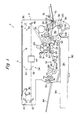
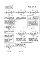
- FIG. l shows a preferred embodiment of the electrostatic copying apparatus in a simplified form.
- the illustrated electrostatic copying apparatus shown generally at 2 has a housing 4.
- a stationary transparent plate 6 on which to place a document (not shown) to be copied is disposed on the upper surface of the housing 4.
- An openable and closable document holding member 7 for covering the transparent plate 6 and the document placed on it is further disposed on the upper surface of the housing 4.
- a rotating drum 8 having an electrostatic photosensitive material disposed on its surface is provided nearly centrally within the housing 4. The rotating drum 8 is rotated in the direction shown by an arrow l0.
- a charging zone l2 Around the rotating drum 8 are defined a charging zone l2, an exposing zone l4, a developing zone l6, a transferring zone l8, a peeling zone 20 and a cleaning zone 22 in this order as viewed in the rotating direction of the drum 8.
- a charging corona discharger 24 is disposed in the charging zone l2.
- a developing device 26 is disposed in the developing zone l6.
- a transfer corona discharger 28 is provided in the transferring zone l8.
- a peeling mechanism 30 is provided in the peeling zone 20.
- a cleaning blade mechanism 32 is disposed in the cleaning zone 22.
- the optical system 34 comprises a movable document illuminating lamp 36, a first, a second and a third movable reflecting mirror 38, 40 and 42, a lens 44 and a reflecting mirror 46.
- the document illuminating lamp 36 and the first, second and third reflecting mirrors 38, 40 and 42 are caused to reciprocate between a position shown by the solid line and a position shown by the two-dot chain line.
- the document illuminating lamp 36 and the first reflecting mirror 38 are moved at a predetermined speed to the right from the positions shown by the solid line
- the second and third reflecting mirrors 40 and 42 are moved at a speed half of the above predetermined speed to the right from the positions shown by the solid line.
- a document placed on the transparent plate 6 is scanned, and an image corresponding to the document is exposed to the surface of the rotating drum in the exposing zone l4 via the first, second, and third reflecting mirrors 38, 40 and 42, the lens 44 and the reflecting mirror 46.
- the copying paper conveying passage 52 is defined by a guide plate 54 and the upper surface of a member 56 cooperating with the guide plate 54, a pair of introduction rollers 58, a pair of guide plates 59, a pair of conveyor rollers 60, a pair of guide plates 62, a pair of conveyor rollers 64, a pair of guide plates 66, a pair of fixing rollers 68 constituting a heat-pressing type fixing device, a pair of guide plate 70, a pair of discharge rollers 72 and a pair of guide plates 74 in this sequence from right to left.
- a copying paper feeding means shown generally at 76 for feeding copying paper sheets one by one to the paper conveying passage 52 is disposed in the right end portion of the housing 4.
- the paper feed means 76 includes a paper placing table 78, a driven delivery roller 80 mounted for free movement between a lowered position shown by the solid line and an elevated position shown by the two-dot chain line, and a driven conveyor roller 82 disposed downstream of the delivery roller 80.
- a layer of stacked copying paper sheets in number less than a certain predetermined number (for example, 50) is placed manually on the table 78 with the front end portion of the paper layer positioned below the delivery roller 80 while the delivery roller 80 is held at the elevated position shown by the two-dot chain line.
- the delivery roller 80 In feeding the paper sheets to the paper conveying passage 52, the delivery roller 80 is lowered and brought into contact with the uppermost paper sheet of the paper layer. By the rotation of the delivery roller 80, the uppermost paper is delivered forwardly and then conveyed forwardly by the action of the conveyor roller 82.
- a receiving tray 84 On the left end of the housing 4 is detachably mounted a receiving tray 84 for collecting copying paper sheets discharged from the downstream end 50 fo the paper conveying passage 52.
- a relatively large nearly parallelpipedal space 86 with an open left end is formed in the lower portion of the housing 4.
- the upper surface of the space 86 is defined by a plate member 88 and its lower surface, by a base plate 90 extending substantially horizontally.
- the front surface of the space 86 is defined by the left end surface of a member 92.
- a copying paper cassette 94 holding a layer of a plurality of copying paper sheets in the stacked state is detachably loaded in the space 86 as shown by a two-dot chain line.
- a copying paper feed passage 96 which extends in curve from the front end of the space 86 to the upstream end portion of the paper conveying passage 52 is disposed within the housing 4.
- the paper feed passage 96 is defined by the lower surface of the member 56, the upper surface of the member 92 cooperating with the member 56, a guide plate 98, a pair of conveyor rollers l00, the right end surface of the member 56 and a guide plate l02 cooperating with it in this sequence from its upstream end to its downstream end.
- the downstream end of the paper feed passage 96 is connected sufficiently smoothly to the upstream end portion of the paper conveying passage 52.
- a driven delivery roller l04 for delivering the copying paper sheets one by one from the paper cassette 94.
- An overlapping-feed preventing member l06 formed of a material having a high coefficient of friction is fixed to the member 92. The overlapping-feed preventing member l06 surely prevents feeding of two or more copying paper sheets at a time from the paper cassette 94 to the paper feed passage 96.
- the operation of the electrostatic copying apparatus 2 described above is summarized as follows:-The rotating drum 8 is rotated in the direction of arrow l0.
- the surface of the rotating drum 8 is charged to a specified polarity by the action of the charging corona discharger 24.
- the exposing zone l4 the document placed on the transparent plate 6 is scanned by the optical system 34 and an image corresponding to the document is optically projected onto the surface of the rotating drum 8.
- a latent electrostatic image corresponding to the image of the document is formed on the surface of the rotating drum 8.
- a toner is applied to the latent electrostatic image by the developing device 26 to develop it to a toner image.
- a copying paper is fed to the paper conveying passage 52 from the paper feed means 76 or from the paper cassette 94 via the paper feed passage 96.
- the fed paper passes through the transferring zone l8 in synchronism with the rotation of the rotating drum 8.
- the transferring zone l8 one surface (upper surface) of the paper is brought into intimate contact with the surface of the rotating drum 8, and the toner image is transferred from the surface of the drum 8 to the contacting surface of the paper by the action of the transfer corona discharger 28.
- the peeling zone 20 the copying paper is peeled from the surface of the rotating drum 8 by the action of the peeling mechanism 30.
- the toner remaining on the surface of the rotating drum 8 after image transfer is removed by the action of the cleaning blade mechanism 32.
- the peeled paper is conveyed further through the paper conveying passage 52, and the toner image on its one surface is fixed by the action of the pair of fixing rollers 68. Thereafter, the copying paper is discharged onto the receiving tray 84. As a result, a copy having a copied image on one surface is obtained.
- an auxiliary unit which is detachably mounted on the electrostatic copying apparatus 2 in place of the paper cassette 94 and which makes it possible to selectively perform the ordinary copying mode described above, and the both surface copying mode and the overlapping copying mode.
- the auxiliary unit will now be described in detail.
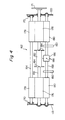
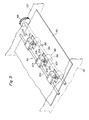
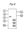
- the illustrated auxiliary unit shown generally at l08, has a supporting base plate ll0.
- the supporting base plate ll0 includes a bottom wall portion ll2 extending in the left-right direction in Figure 3, a front wall portion ll4 extending upwardly from the front end (the right end in Figure 3) of the bottom wall portion ll2, and a rear wall portion ll6 extending upwardly from the rear end (the left end in Figure 3) of the bottom wall portion ll2.
- a front vertical base plate ll8 and a rear vertical base plate l20 are fixed respectively to the front edge and the rear edge of the supporting base plate ll0.
- the front half portions of the front vertical base plate ll8 and the rear vertical base plate l20 are relatively low and in cooperation with the front wall portion ll4, define a relatively low front box-like housing portion l22 having an open upper surface and an open rear surface.
- the rear half portions of the front vertical base plate ll8 and the rear vertical base plate l20 are relatively high, and in cooperation with the rear wall portion ll6, define a relatively high rear box-like housing portion l24 having an open upper surface and an open front surface.
- a cover l26 is applied to the outside of the relatively low front half portion of the front vertical base plate ll8, and likewise, a cover l28 is applied to the outside of the relatively low front half portion of the rear vertical base plate l20.
- the widthwise size between the outside surface of the cover l26 and the outside of the cover l28 corresponds to the widthwise size of the space 86 formed in the housing 4 of the electrostatic copying apparatus 2, and the height of the front box-like housing portion l22 corresponds to the height of the space 86 (see Figure l also).
- a cover l30 is applied to the outside of the relatively high rear half portion of the front vertical base plate ll8, and likewise, a cover l32 is applied to the outside of the relatively high rear half portion of the rear vertical base plate l20.
- a stepped portion is formed in the rear end portion of the cover l30, and an operating panel l34 is disposed in the stepped portion.
- the operating panel has various switches and display lamps mounted thereon as will be described hereinafter.
- An inlet portion shown generally at l36 and a copying paper moving passage shown generally at l38 are provided in the rear box-like housing portion l24, and a copying paper stock means shown generally at l40 and an outlet portion l42 are provided in the front box-like housing portion l22.
- a nearly L-shaped cover plate l44 is mounted on the upper portion of the rear box-like housing portion l24.
- the rear end portion of the cover plate l44 is pivotably mounted on a shaft l46 fixed to the rear end of the front vertical base plate ll8 and the rear vertical base plate l20 so that the cover l44 can be pivoted between a closed position shown by a solid line and an open position shown by a two-dot chain line.
- the cover plate l44 is held at the closed position shown by the solid line, the upper surface of the rear box-like housing portion l24 is covered with the cover plate l44 excepting a portion where the inlet portion l36 is disposed.
- the upper surface of the cover plate l44 constitutes a receiving surface for gathering copying paper sheets.
- a plurality of upper defining plates l48 are provided on the inner surface of the cover plate l44 at suitable intervals in the widthwise and longitudinal directions (as will be described hereinafter, the upper defining plates l48 define the upper side of a part of the copying paper moving passage).
- a nearly C-shaped guide plate l50 is fixedly provided below the cover plate l44 and between the front vertical base plate ll8 and the rear vertical base plate l20.
- a nearly L-shaped guide plate l52 located below the guide plate l50 and a plate member l54 extending forwardly from a position adjoining the front end of the guide plate l52.
- a nearly C-shaped curved reversal passage l56 extending from its upstream end shown by symbol A to its downstream end shown by symbol B is defined.
- that part of the curved reversal passage l56 which ranges from the upstream end A to a position shown by symbol C is defined between the guide plate l50 and the plurality of upper defining plates l48 formed on the inner surface of the cover plate l44.
- the copying paper moving passage shown generally at l38 includes a short-circuit passage l58 which short-circuits between the upstream end portion of the curved reversal passage l56 and its downstream end B. As clearly shown in Figure 3, the short-circuit passage l58 is positioned above the downstream end portion of the curved reversal passage l56.
- Two nearly triangular guide members l60 are spaced in the widthwise direction between the downstream end portion of the curved reversal passage l56 and the short-circuit passage l58 (such guide members l60 will be more specifically described hereinbelow).
- the downstream end portion of the curved reversal passage l56 is defined between the rear end portion of the plate member l54 and the guide member l60.
- the short-circuit passage l58 extends along the upper surface of the guide member l60.
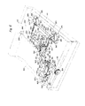
- a multifunctional conveying means shown generally at l62 is disposed at the upstream end A of the curved reversal passage l56 and the upstream end of the shortcircuit passage l58.
- the multifunctional conveying means l62 includes an upper supporting shaft l64, an intermediate supporting shaft l66 and a lower supporting shaft l68 disposed at vertically spaced positions. The both end portions of each of the intermediate supporting shaft l66 and the lower supporting shaft l68 are rotatably mounted on the front vertical base plate ll8 and the rear vertical base plate l20.
- the both end portions of the upper supporting shaft l64 are mounted rotatably on downwardly extending pieces l70 formed on the two side edges of the inner surface of the free end portion (front end portion) of the cover plate l44.
- the rear end portion of the intermediate supporting shaft l66 projects rearwardly beyond the rear vertical base plate l20, and to its projecting end is fixed an input element l7l which may be a sprocket wheel.
- the input element l7l is drivingly connected via a suitable drive linking means (not shown) to the output shaft of a rotary driving source l72 ( Figure 3), which may be an electric motor, disposed within a space surrounded by the guide plate l50.
- the driving source l72 When the driving source l72 is energized and the intermediate supporting shaft l66 and the intermediate conveyor rollers l76 fixed to it are rotated in the direction of arrow l74, the upper conveyor rollers l78, the upper supporting shaft l64 to which the rollers l78 are fixed, the lower conveyor rollers l80, and the lower supporting shaft l68 to which the rollers l80 are fixed are accordingly rotated in the direction of arrow l74.
- the upper conveyor rollers l78 and the intermediate conveyor rollers l76 cooperatively define the upstream end of the curved reversal passage l56, and function as an introduction roller pair which introduces a copying paper sheet from the inlet portion l36 into the curved reversal passage l56 from its upstream end.
- the lower conveyor rollers l80 and the intermediate conveyor rollers l76 cooperate with each other to define the upstream end of the short-circuit passage l58, and function as an introduction roller pair which introduces a copying paper sheet from the curved reversal passage l56 into the short-circuit passage l58 from its upstream end.
- a roller l82 is fixed to the central part in the widthwise direction of the intermediate supporting shaft l66.
- Circumferentially spaced intermediate protrusions l84 extending radially are formed respectively at the both end portions of the roller l82.
- the intermediate protrusions l84 are made of a flexible material such as synthetic rubber.
- the outside diamter of the roller l82 is smaller than the outside diameter of the intermediate conveyor rollers l76, but the intermediate protrusions l84 project radially beyond the peripheral surfaces of the intermediate conveyor rollers l76.
- a roller l86 is fixed to the central part in the widthwise direction of the lower supporting shaft l68, and circumferentially spaced, radially extending lower protrusions l88 are formed in the center in the widthwise direction of the roller l86.
- the lower protrusions l88 are formed of a flexible material such as synthetic rubber as are the intermediate protrusions l84. It will be easily understood by referring to Figures 3 and 4 that the outside diameter of the roller l86 is substantially equal to, or smaller than, the outside diameter of the lower conveyor rollers l80, but the lower protrusions l88 protrude radially beyond the peripheral surfaces of the lower conveyor rollers l80.
- the intermediate protrusions l84 and the lower protrusions l88 are preferably positioned deviatingly without being aligned in the widthwise direction.
- the operation and effect of the intermediate protrusions l84 and the lower protrusions l88 will be described hereinafter.
- each of the two guide members l60 is mounted on the lower supporting shaft l68 at each of two sites between the roller l86 and each of the two lower conveyor rollers l80.
- a rearwardly opened cut l60a is formed at the rear end portion of each of the guide members l60.
- Each of the guide member l60 extends from its one end portion described above in the paper moving direction, namely toward the right in Figure 3, and is biased clockwise in Figure 3 by its own weight whereby its free end abuts against the upper surface of the rear end portion of the plate member l54. If desired, the guide members l60 may be elastically biased clockwise in Figure 3 by using a suitable spring.
- a reverse direction moving means l90 and a pressing means l92 selectively cooperating with it are disposed in the curved reversal passage l56 at a site downstream of the upstream end A by a predetermined distance.
- the reverse direction moving means l90 includes a supporting shaft l94 and three rollers l96 fixed to the supporting shaft l94 in widthwise spaced relationship.
- the opposite end portions of the supporting shaft l94 are rotatably mounted on the front vertical base plate ll8 and the rear vertical base plate l20.
- the rear end portion of the supporting shaft l94 is projected rearwardly beyond the rear vertical base plate l20, and an input element l98 which may be a gear is fixed to its projecting end.
- the input element l98 is drivingly connected to the output shaft of the rotating drive source l72 via a suitable drivingly connecting means (not shown).
- a suitable drivingly connecting means not shown.
- the rotating drive source l72 When the rotating drive source l72 is energized, the supporting shaft l94 and the rollers l96 fixed to it are rotated in the direction shown by an arrow l99.
- openings 200 are formed in the guide plate l50 corresponding respectively to the three rollers l96, and the rollers l96 are exposed upwardly through these openings 200.
- the pressing means l92 includes a supporting shaft 202 disposed at a predetermined position above the guide plate l50, and the opposite end portions of the supporting shaft 202 are rotatably mounted on the front vertical base plate ll8 and the rear vertical base plate l20.
- Three supporting arm pairs 204 are fixed to the supporting shaft 202 in widthwise spaced relationship, and a roller 208 is mounted on each free end of the supporting arm pairs 204 by means of a shaft 206.
- the rear end portion of the supporting shaft 202 is projected rearwardly beyond the rear vertical base plate l20, and the output terminal of an actuating means 2l0 ( Figure 3) which may be an electromagnetic solenoid mounted on the outside surface of the rear vertical base plate l20 is connected to the projecting end of the rear end portion of the supporting shaft 202.
- an actuating means 2l0 Figure 3 which may be an electromagnetic solenoid mounted on the outside surface of the rear vertical base plate l20 is connected to the projecting end of the rear end portion of the supporting shaft 202.
- the roller 2l6 is fixed to a supporting shaft 222, and its peripheral surface is kept in contact with the upper surface of the guide plate l50.
- the supporting shaft 222 is rotatably mounted at tis both end portions on the front vertical base plate ll8 and the rear vertical base plate l20, and drivingly connected to the rotating drive source l72 via a suitable drivingly connecting means (not shown).
- the drive source l72 is energized, the supporting shaft 222 and the roller 2l6 fixed to it are rotated in the direction shown by an arrow l74.
- the rollers 2l8 and 220 are fixed at both end portions to supporting shafts 224 and 226 respectively which are rotatably mounted on the front vertical base plate ll8 and the rear vertical base plate l20.
- the supporting shaft 224 is drivingly connected to the rotary driving source l72 via a suitable drivingly connecting means (not shown).
- a suitable drivingly connecting means not shown.
- an upper movable guide plate 228 and a lower guide plate 230 below it are disposed in the inlet portion l36 positioned at the upper front end portion of the rear box-like housing portion l24.
- the upper movable guide plate 228 constituting an introduction controlling member is selectively held at an introduction position shown by a solid line in Figure 3 and a non-introduction position shown by a two-dot chain line in Figure 3.
- an upwardly extending projecting piece 232 is formed at both side edges of the upper movable guide plate 228, and a pin 234 is fixed to the projecting piece 232.
- the pins 234 are rotatably mounted on the front vertical base plate ll8 and the rear vertical base plate l20, respectively.
- One of the two pins 234 projects rearwardly beyond the rear vertical base plate ll8, and the output terminal of an actuating means 236 which may be an electromagnetic solenoid mounted on the outside surface of the rear vertical base plate ll8 is connected to the projecting end of the pin 234.
- an actuating means 236 which may be an electromagnetic solenoid mounted on the outside surface of the rear vertical base plate ll8 is connected to the projecting end of the pin 234.
- a projecting portion 238 is formed in the center of the downstream end (the left end in Figure 3) of the upper movable guide member 228, and opposite to it, a cut 240 is formed in the upstream end (the right end in Figure 3) of the cover plate l44.
- the projecting portion 238 is located below the cut 240.
- the projecting portion 238 is positioned in the cut 240, and the upper surface of the projecting portion 238 is positioned on substantially the same level as, or slightly upwardly of, the upper surface of the cover plate l44 constituting a receiving surface.
- the lower guide plate 230 is constructed of a rigid member 242 and a flexible member 244.
- the rigid member 242 is fixed between the front vertical base plate ll8 and the rear vertical base plate l20.
- the rigid member 242 has a downstream portion 242a extending while being slightly inclined downwardly and to the left in Figure 3 and an upstream portion 242b extending while being slightly inclined downwardly and to the right.
- the flexible member 244 extends from its one end fixed to the downstream portion 242a of the rigid member 242 to the right in Figure 3. When the upper movable guide plate 228 is held at the introduction position, the flexible member 244 extends in a straight line together with the downstream portion 242a of the rigid member 242 as shown by the solid line in Figure 3.
- the copying paper discharged from the electrostatic copying apparatus 2 passes between the upper movable guide plate 228 and the lower guide plate 230 and is introduced into the paper moving passage l38, more specifically into the curved reversal passage l56
- the copying paper discharged from the electrostatic copying apparatus 2 ( Figure l) is moved along the upper surface of the upper movable guide plate 228, and conducted to the upper surface of the cover plate l44 constituting a receiving surface.
- a detecting means 246 for detecting the copying paper which moves between the upper movable guide plate 228 and the lower guide plate 230 when the upper movable guide plate 228 is held at the introduction position.
- the detecting means 246 may be a normarlly open microswitch having a detecting arm 252 which extends through an opening 240 formed in the lower guide plate 230 and an opening 250 formed in the upper movable guide plate 228.
- a nearly flat plate-like cover plate 254 is mounted on the upper end portion of the front box-like housing portion l22.
- the rear end portion of the cover plate 254 is mounted pivotably on the front vertical base plate ll8 and the rear vertical base plate l20 via a suitable shaft (not shown), and the cover plate 254 can be pivoted and opened counterclockwise as shown by a two-dot chain line from its closed position shown by a solid line.
- the front end of the cover plate 254 is positioned rearwardly of the front end of the front box-like housing portion l22 by a predetermined distance.
- the opening 256 constitutes the aforesaid outlet portion l42 for discharging the copying paper stocked in the paper stock means l40.
- a plurality of guide plates 258 are formed in widthwise spaced relationship on the inside surface of the cover plate 254.
- the paper stock means l40 is disposed within the front box-like housing portion l22.
- the paper stock means l40 includes a paper supporting plate 260 extending in the paper moving direction, namely in the left-right direction in Figure 3.
- the illustrated paper supporting plate 260 is constructed of the front portion of the plate member l54 fixed between the front vertical base plate ll8 and the rear vertical base plate l20 (that portion of the plate member l54 which extends to the right in Figure 3 from the downstream end B of the curved reversal passage l56) and a movable supporting plate piece 262 extending from a position adjacent to the front end of the plate member l54 to a position adjacent to the front wall portion ll4 of the supporting base plate ll0.
- a projecting piece 264 slightly projecting outwardly in the widthwise direction and then extending upwardly is formed at each of the side edges of the rear end portion of the movable supporting plate 262.
- a depression 266 opposite to the projecting piece 264 is formed in the inside surface of each of the front vertical base plate ll8 and the rear vertical base plate l20.
- the projecting piece 264 is positioned within the depression 266, and mounted pivotably by a pin 268 on each of the front vertical base plate ll8 and the rear vertical base plate l20.
- the movable supporting plate piece 262 can be selectively pivoted counterclockwise as shown by a two-dot chain line in Figure 3 from a receiving position shown by a solid line in Figure 3 and elevated. Means for selectively elevating the movable supporting plate piece 262 will be described in detail hereinafter.
- Two stepped portions 270 and 272 spaced from each other longitudinally by a predetermined distance are formed in the plate member l54.
- copying paper sheets of two different sizes designated by JIS B5 and JIS A4 are used.
- the length from the stepped portion 270 to the front wall portion ll4, l1 corresponds to the longitudinal length of the JIS B5 paper
- the length from the stepped portion 272 to the front wall portion ll4, l2 corresponds to the length of the JIS A4 paper.
- the front wall portion ll4 projects upwardly beyond the upper surface of the movable supporting plate piece 262 held at the receiving position, and as will be made clear hereinafter, constitutes paper leading edge restricting plate against which the leading edge of the paper advancing along the upper surface of the paper supporting plate 260 abuts.
- a carry-in roller mechanism 274 is disposed above the rear portion of the paper supporting plate 260.
- the carry-in roller mechanism 274 includes a supporting shaft 276.
- the opposite end portions of the supporting shaft 276 are rotatably mounted on the front vertical base plate ll8 and the rear vertical base plate l20, respectively.
- the rear end portion of the supporting shaft 276 is projected rearwardly beyond the rear vertical base plate l20, and an input element 278 which may be a gear is fixed to its projecting end.
- the input element 278 is drivingly connected to the rotating drive source l72 ( Figure 3) via a suitable drivingly connecting means (not shown), and when the drive source l72 is energized, the supporting shaft 276 is rotated in the direction shown by an arrow 280.
- a supporting member 282 is mounted on the supporting shaft 276 for rotation relative thereto.
- the supporting member 282 has a plate portion 282a extending along, and above, the supporting shaft 276 and downwardly extending portions 282b and 282c extending downwardly from both side edges of the plate portion 282a.
- the downwardly extending portions 282b and 282c are mounted on the supporting shaft 276 for rotation relative thereto.
- the downwardly extending portion 282b extends forwardly (namely, in the paper moving direction), and one end of a shaft 284 is fixed to the free end portion of the downwardly extending portion 282b.
- a carry-in roller 286 is rotatably mounted on the shaft 284.
- a pulley 288 is formed at one end portion of the carry-in roller 286 integrally therewith.
- a pulley 290 is fixed to the supporting shaft 276, and an endless belt 292 is wrapped about the pulleys 288 and 290.
- the carry-in roller 286 is drivingly connected to the supporting shaft 276.
- the carry-in roller 286 is rotated in the direction of arrow 280.
- a rearwardly extending linking piece 294 is fixed to the other downwardly extending portion 282c, and the output terminal of an elevating means 296 which may be an electromagnetic solenoid fixed to the inside surface of the front vertical base plate ll8 is connected to the linking piece 294.
- an elevating means 296 which may be an electromagnetic solenoid fixed to the inside surface of the front vertical base plate ll8 is connected to the linking piece 294.
- the elevating means 296 When the elevating means 296 is in the deenergized state, the supporting member 282 is biased clockwise in Figure 3 by the weight of the supporting member 282 and the carry-in roller 286, and as a result, the carry-in roller 286 is caused to abut against the upper surface of the paper supporting plate 260, as shown in Figures 3 and 7.
- the supporting member 282 may be elastically biased clockwise in Figure 3 by a suitable spring means.
- the elevating means 296 when the elevating means 296 is energized, the supporting member 282 is pivoted counterclockwise in Figure 3 to a position shown by a two-dot chain line in Figures 3 and 7, and the carry-in roller 286 is elevated a predetermined distance to the topmost position from the upper surface of the paper supporting plate 260.
- main holding members 298, 300 and 302 are disposed on both sides of the carry-in roller 286 in the illustrated embodiment.
- an inwardly projecting pin 304 is provided in the front vertical base plate ll8, and likewise, an inwardly projecting pin 306 is provided in the rear vertical base plate l20.
- the main holding members 298 and 300 are mounted on the pin 304, and the main holding member 302, on the pin 306.
- the main holding members 298, 300 and 302 respectively have upwardly projecting pieces 298a, 300a and 302a each at both side portions of their rear end, and these projecting pieces 298a, 300a and 302a are pivotably mounted on the pin 304 and the pin 306, respectively.
- the main portions 298b, 300b and 302b of the main holding members 298, 300 and 302 extend forwardly (namely in the paper moving direction), and their free end portions 298c, 300c and 302c form a predetermined angle with respect to the main portions 298b, 300b and 302b.
- Each of the main holding members 298, 300 and 302 is biased clockwise in Figure 3 by its own weight, The free end portions 298c, 300c and 302c are caused to abut against the upper surface of the paper supporting shaft 260.
- the widthwise size w1 defined by the main holding members 300 and 302 corresponds to the width of the JIS B5 paper, and the widthwise size w2 defined by the main holding members 298 and 302, to the width of the JIS A4 paper.
- a detecting means for detecting the size of the paper sheets stocked in the paper stock means l40.
- openings 299 and 30l are formed in the plate member l54 constituting the paper supporting plate 260, and a light emitting element 303a and a light receiving element 303b are disposed below and above the opening 299, and the light emitting element 303a and the light receiving element 303b, in cooperation with each other, constitute a first detector 303.
- a light emitting element 305a and a light receiving element 305b are disposed below and above the opening 30l, and in cooperation with each other, constitute a second detector 305.
- the opening 299 is located within the widthwise size wl (the width of the JIS B5 paper), and the opening 30l is located outwardly of the widthwise size w1 and within the widthwise size w2 Hence, when the paper sheets stocked on the paper supporting plate 260 of the paper stock means l40 are of the B5 size, only the first detector 303 detects paper (the light from the light emitting element 303a is shut off by the copying paper sheet and does not fall upon the light receiving element 303b), and the second detector 305 does not detect paper (the light from the light emitting element 305a falls upon the light receiving element 305).
- both the first detector 303 and the second detector 305 detect paper.
- both of the first detector 303 and the second detector 205 do not detect paper.
- two subsidiary holding members 308 and 3l0 are disposed in widthwise spaced relationship above the front end portion of the paper supporting plate 260 (and therefore, above the front end portion of the movable supporting plate piece 262).
- the subsidiary holding members 308 and 3l0 respectively have main portions 308a and 3l0a extending forwardly (i.e., in the paper moving direction) from their rear end portions mounted pivotably on pins 3l2 ( Figure 3) fixed to the under surface of the front end portion of the cover plate 254 and free end portions 308b and 3l0b forming a predetermined angle to the main portions 308a and 3l0a.
- the subsidiary holding members 308 and 3l0 are also biased clockwise in Figure 3 by their own weight, and their free end portions 308b and 3l0b are caused to abut against the upper surface of the paper supporting plate 260.
- the positions in the widthwise direction of the subsidiary holding members 308 and 3l0 are prescribed within the widthwise size w1 defined by the main holding members 298 and 300.
- the paper stock means l40 includes an elastic biasing means 3l4 for elastically pivoting the movable supporting plate piece 262 defining the front portion of the paper supporting plate 260 counterclockwise in Figure 3 selectively from a receiving position shown by a solid line in Figure 3.
- a pair of supporting protrusions 3l6 extending upwardly and spaced from each other a predetermined distance in the widthwise direction are fixed to the front end portion of the bottom wall portion ll2 ( Figure 3) of the supporting base plate ll0, and a shaft 3l8 is rotatably mounted on the supporting projections 3l6.
- a push-up members 320 is pivotably mounted on each of the opposite end portions of the shaft 3l8.
- the push-up member 320 has a first arm portion 322 projecting forwardly and a second arm portion 324 projecting upwardly.
- a pin 326 is fixed to the free end portion of the first arm portion 322, and a push-up roller 328 is rotatably mounted on the pin 326.
- To the bottom wall portion ll2 ( Figure 3) of the supporting base plate ll2 ( Figure 3) are also fixed supporting protrusions 330 and 332 which are spaced from each other a predetermined distance in the widthwise direction and upwardly project rearwardly of the pair of supporting protrusions 3l6 by a predetermined distance.
- a rotating shaft 334 is rotatably mounted on the supporting protrusions 330 and 322.
- the opposite end portions of the rotating shaft 334 project beyond the supporting protrusions 330 and 332 respectively, and nearly oval movable members 336 are fixed respectively to the projecting ends of the rotating shaft 334.
- a pin 338 is provided in each of the movable members 336 at a position excentric to the rotating shaft 334.
- a tension spring 340 is stretched between the pin 338 and the second arm portion 324 of each of the push-up members 320.
- a gear 342 is rotatably mounted on the rotating shaft 334, and a spring clutch means 344 for connecting the gear 342 and the rotating shaft 334 selectively is also mounted on the rotating shaft 334.
- the spring clutch means 344 may be of a known type and has a control sleeve 350 on which two engaging protrusions 346 and 348 are formed at an interval of l80 degrees in the circumferential direction.
- a controlling member 352 is disposed in relation to the control sleeve 350.
- One end of the controlling member 325 is pivotably mounted on a pin 354 provided in the bottom wall portion ll2 ( Figure 3) of the supporting base plate ll0.
- An actuating means 356 which may be an electromagnetic solenoid is mounted on the bottom wall portion ll2 of the supporting base plate ll0, and the output terminal of the actuating means 354 is linked to the controlling member 352 via a pin 358.
- the controlling member 352 When the actuating means 356 is in the deenergized state, the controlling member 352 is held at the first position shown by a solid line. When the actuating means 356 is energized, the controlling member 352 is held at a second position shown by a two-dot chain line. At the first position, the free end of the controlling member 352 is positioned against one engaging protrusion 346 of the control sleeve 350, and at the second position, the free end of the controlling member 352 is positioned against the other engaging protrusion 348 of the control sleeve 350.
- a shaft 360 is rotatably mounted between the supporting protrusion 330 and the front vertical base plate ll8.
- the inside end of the shaft 360 projects beyond the supporting protrusion 330, and a gear 362 in mesh with the gear 342 is fixed to this inside end.
- the outside end of the shaft 360 projects outwardly beyond the front vertical base plate ll8, and an input element 364 which may be a gear is fixed to the outside end of the shaft 360.
- the input element 364 is drivingly connected to the rotating drive source l72 ( Figure 3) via a suitable drivingly connecting means (not shown).
- the drive source l72 When the drive source l72 is energized, the shaft 360 and the gear 362 are rotated in the direction shown by an arrow 363, and therefore, the gear 342 is rotated in the direction shown by an arrow 366.
- the tension spring 340 stretched between the pin 338 in the movable member 336 and the second arm portion 324 of the push-up member 320 is in a free condition (not taut), and the push-up member 320 is held at a lowered position shown by a solid line in Figures 3 and 6.
- the push-up roller 328 mounted on the free end portion of the first arm portion 322 of the push-up member 320 makes contact with, or is positioned slightly below, the under surface of the movable supporting plate piece 262 held at the receiving position shown by a solid line.
- the movable supporting plate piece 262 remains kept at the receiving position.
- the push-up roller 328 mounted on the free end portion of the first arm portion 322 of the push-up member 320 acts on the movable supporting plate piece 262 and pivots it counterclockwise in Figure 3.
- the delivery roller l04 of the electrostatic copying apparatus is positioned at the opening 256 constituting the outlet portion l42, and therefore, the pivoting of the movable supporting plate piece 262 and the paper layer existing on it in the counterclockwise direction in Figure 3 is restricted as a result of the paper abutting against the delivery roller l04.
- This restriction causes stretching of the tension spring 340 by a required length. Consequently, the uppermost paper in the paper layer present on the movable supporting plate piece 262 is pressed elastically by the delivery roller l04.
- a sufficient power generated by the rotary driving source l72 ( Figure 3) which may be an electric motor is effectively utilized in holding the movable member 336 at the operating position.
- the actuating means 356 needs only to control the linking of the spring clutch means 344 and its cancellation, and may be a small-sized and inexpensive one whose power consumption is low.
- the front vertical base plate ll8 and the rear vertical base plate l20 are projected up-wardly beyond the upper surface of the paper supporting plate 260, as is clearly seen from Figure 6.
- the rear vertical base plate l20 functions as a restricting plate for restricting one side edge of the copying paper fed to the paper supporting plate 260.
- the illustrated auxiliary unit l08 also has disposed therein a first widthwise moving mechanism 368 and a second widthwise moving mechanism 370 for moving the copying paper fed onto the paper supporting plate 260 in the widthwise direction toward the rear vertical base plate l20 and thereby causing one side edge of the paper to abut substantially against the rear vertical base plate l20.
- a rectangular opening 372 is formed in the plate member l54 defining the rear portion of the paper supporting plate 260.
- a suitable upwardly projecting supporting protrusion (not shown) is fixed to the bottom wall portion ll2 of the supporting base plate ll0, and a shaft 373 extending in the front-rear direction (in a direction perpendicular to the sheet surface in Figure 9) is fixed to the supporting protrusion, and a sleeve member 374 is rotatably mounted on the shaft 373.
- a movable restricting plate 376 is fixed to the sleeve member 374.
- a spring member 378 for elastically biasing the movable restricting plate 376 counterclockwise in Figure 9 is provided between the shaft 373 and the movable restricting plate 376.
- An upwardly projecting supporting protrusion 380 is also fixed to the bottom wall portion ll2 of the supporting base plate ll0, and a nearly L-shaped member 382 is pivotably mounted on the supporting protrusion 380 via a pin 382.
- the member 382 has a first arm portion 384 and a second arm portion 386.
- a rearwardly extending pin 388 is fixed to the free end of the first arm portion 384.
- an actuating means 390 which may be an electromagnetic solenoid mounted on the bottom wall portion ll2 of the supporting base plate ll0 is linked to the free end portion of the second arm portion 386 via a pin 392.
- the actuating means 390 is in the deenergized state in the first widthwise moving mechanism 368, the member 382 is held at a non-operating position shown by a solid line.
- the movable restricting plate 376 is biased counterclockwise in Figure 9 by the elastic biasing action of the spring member 378, and held elastically at a non-operating position (the position shown by a solid line in Figures 6 and 9) at which it abuts against the pin 388 fixed to the first arm portion 384 of the member 382.
- a non-operating position the position shown by a solid line in Figures 6 and 9
- the movable restricting plate 376 is held at the non-operating position, it is positioned below the opening 372.
- the actuating means 390 is energized, the member 382 is pivoted to an operating position shown by a two-dot chain line.
- the movable restricting member 376 is pivoted clockwise in Figure 9 by the pin 388 fixed to the first arm portion 384 of the member 382 against the elastic biasing action of the spring member 378 and held at an operating position shown by a two-dot chain line in Figures 6 and 9. Consequently, the upper portion of the movable restricting plate 376 projects substantially vertically upwardly through the opening 372.
- the distance between the upper portion of the movable restricting plate 376 at the operating position and the rear vertical base plate l20 corresponds to the width of the JIS B5 size paper.
- a rectangular opening 394 is also formed outwardly of the opening 372 in the widthwise direction in the plate member l54 defining the rear portion of the paper supporting plate l60.
- a movable restricting plate 396 formed of spring steel is fixed to the bottom wall portion ll2 of the supporting base plate ll0.
- the movable restricting plate 396 has a bottom portion 398 extending upwardly substantially vertically and a main portion 400 extending from the bottom portion 398 upwardly outwardly (to the left in Figure 9) in the widthwise direction.
- the main portion 400 projects upwardly through the opening 394.
- An L-shaped member 402 is fixed to the inside surface of the main portion 400 in the widthwise direction, and a pin 406 fixed to the output terminal of an actuating means 404 which may be an electromagnetic solenoid and mounted on the bottom wall portion ll2 of the supporting base plate ll0 is inserted between the member 402 and the main portion 400.
- an actuating means 404 which may be an electromagnetic solenoid and mounted on the bottom wall portion ll2 of the supporting base plate ll0 is inserted between the member 402 and the main portion 400.
- the electrostatic copying apparatus 2 shown in Figure l can by itself perform only an ordinary copied image forming mode.
- the paper cassette 94 loaded in the space 86 formed in the lower portion of the housing 4 of the electrostatic copying apparatus 2 and the receiving tray 84 and the pair of guide plates 74 mounted on the left end portion of the housing 4 are removed.
- the auxiliary unit l08 is loaded into the space 86 in place of the paper cassette 94 (in Figure 3, part of the electrostatic copying apparatus 2 is shown by a two-dot chain line).
- the auxiliary unit l08 is mounted in position on the electrostatic copying apparatus 2 by inserting its front housing portion l22 into the space 86 formed in the housing 4 of the electrostatic copying apparatus 2 and causing the front end of the front housing portion l22 to abut against the member 92 provided ahead (to the right in Figure 3) of the space 86.
- the inlet portion l24 of the auxiliary unit l08 is connected to the paper conveying passage 52 of the copying apparatus 2
- the outlet portion l42 of the auxiliary unit l08 is connected to the upstream end of the paper feed passage 96 of the copying apparatus.
- the front end portions of the upper movable guide plate 228 and the lower guide plate 230 provided in the inlet portion l24 project into the housing 4 of the copying apparatus 2 and are positioned against the pair of discharge rollers 72 provided within the housing 4. Furthermore, the opening 256 constituting the outlet portion l42 is positioned against the delivery roller l04 provided within the housing 4 of the copying apparatus 2.
- the operation panel l34 is disposed in the stepped portion formed in the cover l30 of the auxiliary unit l08.
- the power supply switch PS and switches SWl, SW2 and SW3 selectively operated manually are provided on the operating panel l34.
- display lamps Ll, L2, L3 and L4 corresponding to the switches PS, SWl, SW2, and SW3 are provided on the operating panel l34.
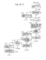
- the operation of the auxiliary unit l08 is controlled as shown below by a control means 498 ( Figure ll), which may be constructed of a microprocessor, according to the selective closing of the switches SWl, SW2 and SW3.
- step n-l the switch SWl ( Figure l0) is closed or not, and then in step n-2, it is determined whether the switch SW2 ( Figure l0) is closed or not. Then, in step n-3, it is determined whether the switch SW3 is closed or not. Before the switch SW3 is closed, step n-3 is followed directly by step n-4 which the lamp L4 is turned on. Then, step n-5 sets in.
- step n-5 if any one of the rotary driving source l72 and the actuating means 236, 2l0, 296, 356, 390 and 404 is in the energized state, it is deenergized. Then, the operation returns to step n-l.
- step n-3 is followed by step n-6, and in step n-6, it is determined whether or not copying paper sheets having a JIS B5 size are in stock in the paper stock means l40 (the determination is based on the outputs of the first detector 303 and the second detector 305 shown in Figure 7).
- step n-6 is followed by step n-7, and in step n-7, it is determined whether or not copying paper sheets having the JIS A4 size are in stock in the paper stock means l40 (the determination is also based on the outputs of the first detector 303 and the second detector 305 shown in Figure 7). Since no paper is in stock in the paper stock means l40, step n-7 is followed by step n-4.
- the rotary driving source l72 in the auxiliary unit l08 is in the deenergized state; the actuating means 236 is in the deenergized state, and the upper movable guide plate 228 in the inlet portion l36 is held at the non-introduction position shown by the two-dot chain line; the actuating means 2l0 is in the deenergized state, and the pressing means l92 is held at the non-introduction position shown by the two-dot chain line; the elevating means 296 ( Figure 7) is in the deenergized state and the carry-in roller 286 is at the position shown by the solid line; and the actuating means 356 ( Figure 6) is in the deenergized state and the push-up members 320 are held at the lowered positions shown by the solid lines and therefore the movable supporting plate piece 262 is held at the receiving position shown by the solid line. Furthermore, the actuating means 390 and 404 shown in Figure 6 are
- a copying paper sheet having a copied image formed on one surface thereof by being fed from the paper feed means 76 ( Figure l) in the copying apparatus 2 into the paper conveying passage 52 ( Figure l) and conveyed through the paper conveying passage 52 is moved from the pair of discharge rollers 72 along the upper surface of the upper movable guide plate 228, and discharged onto the upper surface of the cover plate l44, i.e. its paper receiving surface.
- the auxiliary unit l08 is only such that the upper surface of the cover plate l44 functions as a receiver tray for gathering copies.
- the switch SWl ( Figure l0) is manually closed.
- the operation goes to step n-8 from step n-l, and the display lamp L2 is turned on.
- the operation goes to step n-9, and the actuating means 236 is energized to hold the upper movable guide plate 228 in the inlet portion l36 at the introduction position shown by the solid line.
- the upstream end of the upper movable guide plate 228 is positioned above the nipping site of the pair of discharge rollers 72 in the copying apparatus 2, and the upstream end of the lower guide plate 230 is positioned below the nipping site of the pair of discharge rollers 72.
- the downstream end of the upper movable guide plate 228 is positioned above the nipping site of the introduction rollers, i.e. rollers l76 and l78, located at the upstream end of the curved reversal passage l56 in the auxiliary unit l08, and below the cover plate l44.
- the downstream end of the lower guide plate 230 is positioned below the nipping position of the rollers l76 and l78.
- a copying paper sheet having a copied image formed on its one surface (upper surface) by being fed from the paper feed means 76 ( Figure l) in the copying apparatus 2 into the paper conveying passage 52 ( Figure l) and conveyed through the paper conveying passage 52 is conducted between the upper movable guide plate 228 and the lower guide plate 230 from the pair of discharge rollers 72 and sent to the nipping site of the rollers l76 and l78 through the guide plates 228 and 230.
- step n-l0 sets in, and in step n-l0, it is determined whether or not the detecting means 246 disposed in the inlet portion l36 has detected the leading edge of the copying paper (namely, whether or not the leading edge of the paper has reached and closed the detecting means 246).
- step n-ll sets in, and a paper stock number counter 4l0 ( Figure ll) built in the control means 408 counts up.
- step n-l2 sets in, and a paper size detecting timer 4l2 ( Figure ll) built in the control means 408 starts to measure the time.
- step n-l3 sets in, and in step n-l3, the rotary driving source l72 is energized to rotate the rollers l76, l78, l80, 2l6, 2l8 and 220 in the direction of arrow l74, the roller l96 in the reverse direction moving means l90 in the direction shown by an arrow l98, and the carry-in roller 286 in the carry-in roller mechanism 274 in the direction shown by an arrow 280.
- the copying paper which has been conducted to the nipping site of the rollers l76 and l78 through the space between the upper movable guide plate 228 and the lower guide plate 230 is introduced into the curved reversal passage l56 by the action of the rollers l76 and l78 and move in the reversal passage l56 in the direction shown by an arrow 2l2.
- the intermediate protrusion l84 projecting beyond the circumferential surface of the roller l76 acts on the leading edge portion of the paper passing through the nipping site of the rollers l76 and l78 to displace it slightly upwardly, and thus surely prevents the leading edge of the paper from moving downwardly along the circumferential surface of the roller l76 and being introduced into the nipping site of the rollers l76 and l80 located at the upstream end of the short-circuit passage l58.
- the copying paper introduced into the reversal passage l56 and moved in the direction of arrow 2l2 advances between the guide plate l50 and the roller 2l6, and further moved in the direction of arrow 2l2 by the action of the roller 2l6.
- the roller l96 in the reverse direction moving means l90 is rotated in the direction shown by an arrow l98, but since slippage is generated between the paper and the roller l96, the movement of the paper in the direction of arrow 2l2 is never hampered by the roller l96.
- step n-l4 sets in, and it is determined whether or not the detecting means 246 disposed in the inlet portion l36 has detected the trailing edge of the copying paper (namely whether the trailing edge of the paper has passed and opened the detecting means 246).
- step n-l5 sets in.
- step n-l5 it is determined whether or not the paper detecting timer 4l2 ( Figure ll) which starts measuring the time in step n-l2 has measured the time exceeding a predetermined time.
- the time required from the arrival of the leading edge of the paper at the detecting means 246 until the trailing edge of the paper has gone past the detecting means 246 is shorter than the aforesaid predetermined time.
- the time required from the arrival of the leading edge of the paper at the detecting means 246 until the trailing edge of the paper has gone past the detecting means 246 is longer than the predetermined time.
- step n-l6 sets in, and in step n-l6, the paper detecting time 4l2 is reset.
- step n-l7 sets in, and in step n-l7, an A4 flag A4F ( Figure ll) built in the control means 408 is set at "l".
- step n-l8 sets in, and in step n-l8, the paper detecting timer 4l2 is reset.
- step n-l9 sets in, and in step n-l9, a B5 flag B5F ( Figure ll) built in the control means 408 is set at "l".
- step n-20 sets in, and in step n-20, it is determined whether or not the switch SWl is closed. Since SWl is closed (the both surface image forming mode is selected), step n-2l then sets in. In step n-2l, there is waiting for a predetermined period of time. This predetermined period of time is slightly longer than the time required from the passing of the trailing edge of the paper past the detecting means 246 until it passes the nipping site of the rollers l76 and l78.
- the trailing edge of the paper passes the nipping site of the rollers l76 and l78.
- the intermediate protrusions l84 projecting beyond the circumferential surface of the roller l76 act on the trailing edge of the paper and force it downwardly toward the guide plate l50.
- the trailing edge of the paper is not nipped by the rollers l76 and l78, but is surely nipped by the rollers l76 and l80.
- step n-22 sets in, and in step n-22, the actuating means 2l0 is energized to lower the pressing means l92 to the operating position shown by the two-dot chain line. Consequently, the roller 208 in the pressing means l92 presses the paper existing below it against the roller l96 rotating in the direction of arrow l98. Accordingly, the paper which has been moved in the direction of arrow 2l2 is now moved by the roller l96 in an opposite direction, i.e.
- step n-23 sets in, and in step n-23, there is waiting for a predetermined period of time. This predetermined period of time is slightly longer than the time required for the leading edge of the paper moved in the opposite direction (the direction of arrow 2l4) to reach the nipping site of the rollers l76 and l80.
- step n-24 sets in, and in step n-24, the actuating means 2l0 is deenergized to elevate the pressing means l92 to the non-operating position shown by the solid line.
- step n-25 sets in, and in step n-25, there is waiting for a predetermined period of time.
- This predetermined time is slightly longer than the time required for the leading edge of the paper which has been fed to the paper stock means l40 to abut against the front wall portion ll4 of the supporting base plate ll0 (i.e., the paper leading edge restricting plate).
- the paper is conveyed through the short-circuit passage l58 by the action of the rollers l76 and l80 and introduced into the paper stock means l40.
- the paper is made slightly wavy in the widthwise direction by the cooperative action of the intermediate protrusions l84 projecting beyond the circumferential surface of the roller l76 and the lower protrusion l88 projecting beyond the circumferential surface of the roller l80, whereby the stiffness of the paper in the moving direction is increased, and the paper can be accurately introduced into the paper stock means l40 through the short-circuit among l58.
- the paper which has been introduced into the paper stock means l40 advances along the upper surface of the paper supporting plate 260 and then below the carry-in roller 286 lowered to the position shown by the solid line (or a position above the position shown by the solid line by the thickness of the paper layer stocked in the paper stock means l40) and being rotated in the direction of arrow 280.
- the paper is further advanced by the action of the carry-in roller 286 and its leading edge abuts against the front wall portion ll4 of the supporting base plate ll0. After the leading edge of the paper has abutted against the front wall portion ll4, further advancing of the paper is hampered, and therefore, slippage is generated between the paper and the carry-in roller 286.
- the carry-in roller 286 continues to be lowered to the position shown by the solid line for some time.
- the paper has low stiffness, the paper is curved upwardly immediately ahead of the carry-in roller 286, and then the trailing end of the paper goes past the carry-in roller 286 and moves upwardly of the carry-in roller 286 (whereupon the paper fed next to the paper stock means l40 comes below the previous paper).
- the actuating means 390 or 404 may be energized several times temporarily to hold the movable restricting plate 376 or 396 at the operating position shown by the two-dot chain line in Figures 6 and 9 several times temporarily and thus perform a pre-operation for the operation of determining the widthwise position of the paper to be described.
- step n-26 sets in, and in step n-26, the actuating means 296 ( Figure 7) is energized to elevate the carry-in roller 286 to the topmost position shown by the two-dot chain line.
- step n-27 sets in, and it is determined whether a B5 flag B5F ( Figure ll) in the control means 408 is "l" or not.
- the actuating means 390 ( Figures 6 and 9) is energized to hold the movable restricting plate 376 at the operating position shown by the two-dot chain line in Figures 6 and 9.
- the movable restricting plate 376 acts on the front side edge of the JIS B5 size paper fed to the paper supporting plate l60 to force the paper to the right in Figure 9 and the rear side edge of the paper is caused to abut substantially against the rear vertical base plate l20 (i.e., the paper one side edge restricting plate).
- the paper is set accurately at a predetermined widthwise position.
- step n-29 sets in, and in step n-29, there is waiting for a predetermined period of time which may be short.
- step n-30 sets in, and in step n-30, the actuating means 390 ( Figures 6 and 9) are deenergized to return the movable restricting plate 376 to the non-operating position shown by the solid line in Figures 6 and 9.
- step n-3l sets in, and in step n-3l, the B5 flag B5F ( Figure ll) is reset.
- step n-27 when in step n-27, the B5 flag B5F is not “l” (in which case, A4F is "l"), step n-32 sets in, and in step n-32, the actuating means 404 ( Figures 6 and 9) is energized to hold the movable restricting plate 396 at the operating position shown by the two-dot chain line in Figures 6 and 9.
- the movable restricting plate 376 acts on the front side edge of the JIS A4 size paper fed to the paper supporting plate l60 to force the paper to the right in Figure 9 and cause the rear side edge of the paper to abut substantially against the rear vertical base plate l20 (i.e., the paper one side edge restricting plate).
- the paper is surely set at a predetermined widthwise position.
- step n-33 sets in, and in step n-33, there is waiting for a predetermined period of time which may be short.
- step n-34 sets in, and in step n-34, the actuating means 404 ( Figures 6 and 9) is deenergized to return the movable restricting plate 396 to the non-operating position shown by the solid line in Figures 6 and 9.
- step n-35 sets in, and in step n-35, the A4 flag A4F ( Figure ll) is reset.
- Step n-3l or step n-35 is followed by step n-36, and in step n-36, the actuating means 296 ( Figure 7) is deenergized to lower the carry-in roller 286 to the position shown by the solid line (or a position above the position shown by the solid line by the thickness of the paper layer already stocked in the paper stock means l40). In this way, the required number of copying paper sheets having the JIS B5 size or the JIS A4 size are stocked in the paper stock means l40. Thereafter, step n-37 sets in and in step n-37, it is determined whether or not the counted value of the paper stock number counter 4l0 of the control means 408 has reached a predetermined number.
- This predetermined number is the allowable number of paper sheets that can be stocked in the paper stock means l40.
- the operation returns to step n-l.
- step n-38 sets in.
- the actuating means 236 is deenergized to return the upper movable guide plate 228 of the inlet portion l36 to the non-introduction position shown by the two-dot chain line.
- step n-6 is followed by step n-39.
- the actuating means 390 ( Figures 6 and 9) is energized to hold the movable restricting plate 376 at the operating position shown by the two-dot chain line in Figures 6 and 9.
- step n-7 is followed by step n-40.
- the actuating means 404 ( Figures 6 and 9) is energized to hold the movable restricting plate 396 at the operating position shown by the two-dot chain line in Figures 6 and 9.
- the widthwise position of the paper is restricted when the paper of the JIS A4 size is discharged fromthe paper stock means l40 in the manner to be described hereinafter.
- Step n-39 or n-40 is then followed by step n-4l.
- the actuating means 296 ( Figure 7) is energized to elevate the carry-in roller 286 to the topmost position shown by the two-dot chain line.
- step n-42 sets in, and in step n-42, the actuating means 236 is energized. If at this time, the upper movable guide plate 228 in the inlet portion l36 is at the introduction position shown by the solid line, the actuating means 236 is deenergized to return the upper movable guide plate 228 to the non-introduction position shown by the two-dot chain line.
- step n-43 sets in, and in step n-43, the actuating means 356 ( Figures 6 and 8) is engergized to elevate the pressing members 320 of the elastic biasing means 3l4.
- the movable supporting plate piece 262 defining the front half portion of the paper supporting plate 260 is elevated as shown by the two-dot chain line in Figure 3, and the uppermost paper in the paper layer of the movable supporting plate piece 262 is pressed elastically against the delivery roller l04 of the electrostatic copying apparatus 2.
- step n-44 sets in, and in step n-44, the paper stock number counter 4l0 of the control means 408 is reset. Then, the operation returns to step n-l.
- the delivery roller l04 is rotated counterclockwise in Figure 3 by, for example, closing a copying switch (not shown) disposed in the electrostatic copying apparatus 2.
- the topmost paper is discharged from the paper stock means l04 through the outlet portion l42, introduced into the paper feed passage 96 ( Figure l) of the copying apparatus 2 and then introduced into the paper conveying passage 52 through the paper feed passage 96.
- step n-6 is followed by step n-7, and the operation returns to step n-l via steps n-4 and n-5.
- step n-2 is followed by step n-45, and the display lamp L3 is turned on.
- step n-20 sets in.
- a copying paper having a copied image formed on its one surface (upper surface) by being conveyed through the paper conveying passage 52 of the electrostatic copying apparatus 2 is introduced from the pair of discharge rollers 72 in the copying apparatus 2 into the curved reversal passage l56 through the space between the upper movable guide plate 228 and the lower guide plate 230 held at the introduction position shown by the solid line in Figure 3 as in the both surface image forming mode.
- step n-20 it is determined whether the switch SWl is closed or not. Since in the overlapping image forming mode, the switch SWl is opened and the switch SW2 is closed, step n-20 is followed by step n-46.
- step n-46 there is waiting for a predetermined period of time.
- This predetermined period of time is slightly longer than the time required for the paper introduced into the curved reversal passage l56 to be fed into the paper stock means l40 through the curved reversal passage l56 as shown hereinafter and then abut at its leading edge against the front wall portion ll4 of the supporting base plate ll0 (i.e., the paper leading edge restricting plate).
- the paper introduced into the reversal passage l56 is conveyed through the reversal passage l56 by the action of the rollers 2l6, 2l8 and 220 rotating in the direction ofarrow l74 and introduced into the paper stock means l40.
- the guide member l60 ( Figures 3 and 4) is disposed in the downstream end portion of the reversal passage l56, the aforesaid upward movement of the leading edge portion of the paper is surely avoided and the paper is surely introduced into the paper stock means l40 from the curved reversal passage l56.
- the copying paper introduced into the paper stock means l40 is further advanced by the action of the carry-in roller 286 and its leading edge is caused to abut against the front wall portion ll4 of the supporting base plate ll0. Thereafter, the aforesaid steps n-26 to n-38 are carried out, and as in the both surface image forming mode, the widthwise position of the paper fed into the paper stock means l40 is restricted as is required.
- the actuating means 390 or 404 may be energized several times temporarily to hold the movable restricting plate 376 or 396 several times temporarily at the operating position shown by the two-dot chain line in Figures 6 and 9, and thus perform a pre-operation for the operation of restricting the widthwise direction of the paper.
- the switch SW3 ( Figure l0) is manually closed as in the both surface image forming mode (whereupon the switch SW2 closed up to that time is opened). Consequently, as in the both surface image forming mode, the aforesaid steps n-4l to n-44 are carried out via step n-39 or n-40.
- the delivery roller l04 is rotated counterclockwise in Figure 3 by, for example, closing a copying switch (not shown) provided in the electrostatic copying apparatus 2 as in the both surface image forming mode described hereinabove.
- a copying switch not shown
- the uppermost copying paper is discharged from the paper stock means l04 through the outlet portion l42, introduced into the paper feed passage 96 ( Figure l) of the copying apparatus 2 and introduced into the paper conveying passage 52 through the paper feed passage 96.
- step n-6 is followed by step n-7 and then the operation returns to step n-l via steps n-4 and n-5, as in the both surface image forming mode.
- the cover plate l44 When jamming of the paper occurs in the inlet portion l36, the curved reversal passage l56 or the short-circuit passage l58 within the auxiliary unit l08, the cover plate l44 is opened to the position shown by the two-dot chain line in Figure 3. This permits very easy removal of the paper that has jammed up.
- the auxiliary unit l08 When jamming occurs in the paper stock means l40 or the outlet portion l42, the auxiliary unit l08 is moved to the left in Figure 3 and detached from the copying apparatus 2. Then the cover plate 254 is opened to the position shown by the two-dot chain line in Figure 3. This permits very easy removal of the paper that has jammed up. Paper jamming can be detected by a jam detecting means (not shown) which may be of any suitable type known per se .
- control method is simplified by establishing controlling of the electrostatic copying apparatus 2 and controlling of the auxiliary unit l08 independently from each other without exchanging control signals between the copying apparatus 2 and the auxiliary unit l08.
- a unique control system is employed in the copying apparatus 2 in addition to the ordinary copying operation control system. This unique control system will be described in detail below.
- the electrostatic copying apparatus 2 has provided therein a first, a second and a third paper detecting means Sl, S2 and S3.
- the first paper detecting means Sl is disposed in the paper feed means 76 and detects whether or not a copying paper exists in the paper feed means 76, or more specifically, whether or not a paper sheet is placed on the paper placing table 78 of the paper feed means 76.
- the first paper detecting means Sl may be constructed of a microswitch known per se (or a reflection-type or transmission-type photosensor, etc.).
- the second paper detecting means S2 is disposed in relation to the space 86 into which the paper cassette 94 or the auxiliary unit l08 is selectively loaded, and detects whether or not a copying paper sheet exists in the paper cassette 94 when the cassette 94 is loaded in the space 86, and whether or not copying paper sheets are fed into and stocked in the paper stock means l40 when the auxiliary unit l08 is loaded in the space 86.
- the second paper detecting means S2 may be constructed of a reflection-type photosensor known per se .
- the paper detecting means S3 is disposed in the downstream end portion of the paper conveying passage 52, and detects the paper which goes past it.
- the third paper detecting means S3 may be constructed of a microswitch known per se (or a reflection-type or transmission-type photosensor, etc.).
- the electrostatic copying apparatus 2 also has provided therein a copying operation start switch means CS and a required copy number setting means 452.
- the copying operation start switch CS is disposed on an operating panel (not shown) provided on the upper surface or front surface of the housing 4 of the electrostatic copying apparatus, and is temporarily closed by the operator when starting the copying action of the electrostatic copying apparatus 2.
- the required copy number setting means 452 includes an input means disposed on the operating panel (the input means may be constructed of l0 keys corresponding to the numerals 0 to 9. The operator can set the required number of copies from a single document by operating the input means.
- the operating panel also has disposed therein a lamp PLl for displaying the presence or absence of a copying paper sheet and a lamp PL2 for displaying paper jamming.
- An operation control means 454 which can be constructed from a microprocessor is also provided in the copying apparatus 2.
- the operation control means 454 has built therein a copy number counting means 456 composed of a counter, a time measuring means 458 composed of a timer, and a discriminating means 460 composed of flags.
- the operation control means 454 controls the operations of the various elements of the copying apparatus 2, and thus controls the copying operation of the copying apparatus 2.
- step m-l determines whether or not the copying operation start switch means CS has been closed.
- step m-2 sets in, and it is determined whether or not the first paper detecting means Sl has detected paper, and therefore whether or not exists in the second paper feed means 76.
- step m-3 sets in, and it is determined whether or not the second paper detecting means S2 has detected paper.
- the second paper detecting means S2 does not detect any paper.
- the paper cassette 94 is loaded in the copying apparatus 2 but no paper exists in it, the second paper detecting means S2 does not detect paper.
- step m-4 sets in.
- step m-4 the paper absence displaying lamp PLl is turned on to warn the operator that the copying operation cannot be carried out because no paper exist. Then, the operation returns to m-l.
- step m-3 is followed by step m-5.
- step m-5 a third paper feed mode in which the delivery roller l04 is rotated to introduce paper from the paper cassette 94 into the paper conveying passage 52 through the paper feed passage 96 is established, and the copying operation is carried out. It will be easily understood that by this copying operation, the ordinary image forming mode is performed, and an ordinary copy having a copied image of a single document formed on its one surface is obtained. Then, step m-6 sets in, and it is determined whether or not paper jamming has occurred.
- Occurrence of paper jamming can be determined on the basis of the detection of paper by the third paper detecting means S3, or more specifically, by whether within a predetermined period of time from the delivery of paper from the paper cassette, the third paper detecting means S3 has once detected paper but later fails to detect paper (namely whether the paper goes past the third paper detecting means S3 and is discharged onto the receiver tray 84).
- step m-7 sets in, and in step m-7, the paper jamming displaying lamp PL2 is turned on. Consequently, the operator is warned of paper jamming, and the operator can accordingly remove the paper that has jammed up. Then, the operation returns to step m-l.
- step m-6 it is confirmed in step m-6 that no paper jamming has occurred, step m-8 sets in, and in step m-8, the copy number counter means 456 counts up by one. Then, step m-9 sets in, and in step m-9, it is determined whether the counted value of the copy number counter means 456 is equal to the preset value of the required copy number setting means 452. When the counted value is smaller than the preset value, step m-5 again sets in and the next copying operation is carried out in the third paper feed mode. On the other hand, the operation of producing the required number of copies has been carried out and the counted value is equal to the preset value in step m-9, step l0 sets in.
- step m-l0 the copy number counter means 456 is reset (namely, the counted value is returned to zero). Then, step m-ll sets in, and the required copy number setting means 452 is reset (namely, the preset value is returned to l). After this initial condition is attained, the operation returns to step m-l.
- step m-2 When in step m-2 the first paper detecting means Sl detects paper, namely when paper exists in the paper feed means 76, step m-2 is followed by step m-l2. In step m-l2, it is determined as in step m-3 whether the second paper detecting means S2 detects paper.
- step m-5 sets in, and as stated above, the third paper feed mode is established and the copying operation is carried out.
- the third paper feed mode of delivering paper from the cassette 94 is established prior to first and second paper feed modes to be described, and the copying operation in accordance with an ordinary image forming mode is carried out irrespective of whether paper exists in the paper feed means 76.
- step m-l3 sets in.
- a first paper feed mode in which paper is fed from the paper feed means 76 into the paper conveying passage 96 is established, and the copying operation is carried out. Accordingly, in the illustrated embodiment, the first paper feed mode is established prior to the second paper feed mode to be described, and the copying operation is carried out.
- a copied image is formed on one surface of paper while the paper is conveyed from the paper feed means 76 through the paper conveying passage 52.
- the auxiliary unit l08 is loaded in the copying apparatus 2 and the upper movable guide plate 228 in its inlet portion l36 is held at the introduction position shown by the solid line in Figure 3 (and therefore in the first cycle of the image forming step in the both surface image forming mode or the overlapping image forming mode)
- the above paper is introduced into the auxiliary unit l08 from the paper conveying passage 52 and stocked in the paper stock means l40 in the auxiliary unit l08.
- Step m-l3 is followed by step m-l4, and in step m-l4, it is determined whether or not the time measuring means 458 built in the operation control means 454 has completed time measuring. Since the time measuring means 458 starts time measuring in step m-l9 to be described, it has not yet completed measuring at the time of carrying out the first cycle of the copying operation in the first paper feed mode, and thus step m-l5 sets in. In step m-l5, it is determined whether or not paper jamming has occurred.
- Occurrence of paper jamming can be determined as in step m-6 on the basis of the detection of paper by the thrid paper detecting means, or more specifically, by whether within a predetermined period of time from the delivery of paper from the paper feed means 76, the third paper detecting means S3 has once detected paper but later fails to detect it (namely whether the paper has gone past the third paper detecting means S3 and is introduced into the auxiliary unit l08, or discharged onto the cover plate l44 of the auxiliary unit l08 or the receiver tray 84).
- step m-l6 sets in, and in step m-l6, paper jamming displaying lamp PL2 is turned on to warn the operator of paper jamming.
- step m-37 sets in, and in step m-37, it is determined whether the copying operation start switch CS is closed or not.
- the operation returns to step m-l3.
- step m-l5 it is confirmed in step m-l5 that no paper jamming has occurred
- step m-l7 sets in, and the copying number counter means 456 counts up by one.
- step m-l8 sets in, and it is determined whether or not the counted value of the copy number counter means 456 is l, namely whether or not the copying operation has been carried out through one cycle in the first paper feed mode.
- step m-l9 sets in.
- the time measuring means 458 starts time measuring.
- the time measuring means 458 completes time measuring after it has measured a predetermined time.
- the predetermined period of time is set at a time period corresponding to (for example, slightly longer than) the time required from the time when the trailing edge of the copying paper has gone past the third paper detecting means S3 (namely the time when the time measuring means 458 has started measuring) in the state where the auxiliary unit l08 is loaded in the copying apparatus 2 and the upper movable guide plate 228 of its inlet portion l36 is held at the introduction position shown by the solid line in Figure 3 until the paper introduced into the auxiliary unit l08 is fed to the paper stock means l40 through the curved reversal passage l56 or from the curved reversal passage l56 via the short-circuit passage l58.
- step m-20 sets in.
- step m-l8 is followed by step m-20 without going through step m-l9.
- step m-20 it is determined whether or not the counted value of the copy number counting means 456 is equal to the preset value of the required copy number setting means 452.
- the operation returns to step m-l3, and the next copying operation is carried out in the first paper feed mode.
- step m-l4 again sets in, the time measuring means 458 which started measuring in step m-l9 has already measured the aforesaid predetermined period of time.
- step m-l4 is then followed by step m-2l.
- step m-2l it is determined whether the second paper detecting means S2 detects paper.
- the first paper is fed into, and stocked in, the paper stock means l40 of the auxiliary unit l08 before the time measuring means 458 has completed time measuring.
- the second paper detecting means S2 detects paper.
- step m-22 sets in, and in step m-22, the discriminating means 460 built in the operation control means 454 is set. Then, step m-23 sets in, and the time measuring means 458 which has completed measuring is reset. Thereafter, step m-l5 is again sets in.
- step m-l8 is followed by step m-20 without going through step m-l9, and therefore, the time measuring means 458 does not start measuring.
- step m-l4 is followed by step m-l5 without going to step m-2l.
- step m-23 sets in without going to step m-22 and therefore without setting the discriminating means 460.
- the second paper detecting means S2 also detects paper. But in such a case, step m-l2 or step m-3 is followed by step m-5, and therefore step m-2l does not set in.
- the detection of paper by the second paper detecting means S2 in step m-2l means that the auxiliary unit l08 is loaded in the electrostatic copying apparatus 2 and the paper stock means l40 of the auxiliary unit l08 has paper stocked therein.
- step m-20 is followed by step m-24 where the copy number counter means 456 is reset.
- step m-25 sets in, and it is determined whether or not the discriminating means 460 is set in step m-22, namely whether or not the copying mode is the both surface image forming mode or the overlapping image forming mode.
- step m-26 sets in, and in step m-26, the required copy number setting means 452 is reset.
- step m-l again sets in.
- step m-27 sets in and it is determined whether or not the copying operation start switch means CS is closed.
- step m-28 sets in.
- the second paper feed mode in which the delivery roller l04 is rotated to introduce paper from the paper stock means l40 of the auxiliary unit l08 into the paper conveying passage 52 through the paper feed passage 96 is established, and the copying operation is carried out.
- Step m-28 is thus followed by step m-29, and in step m-29, it is determined whether or not paper jamming has occurred.
- step m-30 sets in, and in step m-30, the paper jamming displaying lamp PL2 is turned on. Thus, the operator is warned of paper jamming, and the operator can accordingly remove the paper that has jammed up.
- step m-3l sets in, and the counted value of the copy number counter means 456 counts up by one.
- step m-32 sets in, and it is determined whether or not the counted value of the copy number counter means 456 is equal to the preset value of the required copy number setting means 452.
- step m-33 sets in, and it is determined whether or not the second paper detecting means S2 detects paper.
- step m-32 when the counted value is smaller than the preset value in step m-32, paper sheets in a number obtained by subtracting the counted value from the preset value remain in the paper stock means l40 of the auxiliary unit l08, and therefore, the second paper detecting means S2 detects paper. In this case, step m-28 again sets in, and the next copying operation is carried out in the second paper feed mode.
- step m-32 When the required number of copies has been produced by the copying operation in the second paper feed mode and therefore the counted value of the copy number counter means 456 becomes equal to the preset value of the required copy number setting means 452 in step m-32, step m-32 is followed by step m-34 where the discriminating means 460 is reset. Then, step m-26 sets in, and in step m-26, the required copy number setting means 452 is reset. Thus, the initial state is attained, and thereafter, the operation returns to step m-l.
- the counted value of the copy number counter means 456 is smaller than the preset value of the required copy number setting means 452 in step m-32, and therefore in spite of the fact that step m-32 is followed by step m-33, no paper remains in the paper stock means l40 of the auxiliary unit l08 if a number obtained by subtracting the counted value from the preset value is equal to the number of paper sheets that have jammed up.
- step m-33 is followed by step m-35, and in step m-35, the preset value of the required copy number setting means 452 is changed to a value obtained by subtracting the counted value from the originally preset value to make up for the paper sheets which have jammed up.
- step m-36 sets in, and the discriminating means 460 is reset. Thereafter, the operation returns to step m-l. Accordingly, the operator can additionally perform the both surface image forming mode or the overlapping image forming mode without the need for counting the number of paper sheets which have jammed up, and for re-setting the required copy number setting means 452 at a value including the additionally required number of paper sheets.
- controlling of the electrostatic copying apparatus 2 and controlling of the auxiliary unit l08 are established independently from each other without exchanging control signals between the copying apparatus 2 and the auxiliary unit l08. Since the unique control method described above is employed in the electrostatic copying apparatus 2, the first to third paper feed modes are properly selected and set. Accordingly, the ordinary image forming mode and the both surface image forming mode and/or the overlapping image-forming mode can be selectively carried out very easily and accurately without the need for any additional complex manual operation.
Abstract
Description
- This invention relates to an electrostatic copying apparatus and an auxiliary unit to be mounted detachably on it. More specifically, this invention pertains to an electrostatic copying apparatus and an auxiliary unit which is detachably mounted on it and can diversify the mode of forming a copied image.
- As is well known to those skilled in the art, "multimode" electrostatic copying apparatuses have recently been proposed and come into commercial acceptance which can selectively perform an ordinary copying mode (the mode whereby a copied image of a single document is formed on one surface of a copying paper), and a both surface copying mode (the mode whereby a copied image of a document is formed on one surface of a copying paper and then a copied image of another document is formed on the other surface of the paper) and/or an overlapping copying mode (the mode whereby a copied image of a document is formed on one surface of a copying paper and then a copied image of another document is overlappingly formed on the aforesaid one surface of the paper).
- Conventional multimode electrostatic copying apparatuses, however, have various problems to be solved. The conventional multimode electrostatic copying apparatuses are equipped with various elements for selectively performing the both surface copying mode and/or the overlapping copying mode in addition to the ordinary copying mode as parts essential to the apparatus itself. In the electrostatic copying apparatus market, there is a first demand for multimode electrostatic copying apparatuses which can selectively perform the both surface copying mode and/or the overlapping copying mode in addition to the ordinary copying mode and are relatively expensive, and there is also a second demand for "single mode" electrostatic copying apparatuses which can perform the ordinary copying mode and are relatively inexpensive. The conventional multimode electrostatic copying apparatuses can meet the first demand but cannot meet the second demand. The manufacturers and sellers, therefore, should manufacture and sell the single mode electrostatic copying apparatuses meeting the second demand separately from the multimode apparatuses. This complicates a control of manufacture and stock of apparatuses and entails an increase in cost. The consumer initially purchases a single mode electrostatic copying apparatus with which he is fully satisfied, but when a need arises later to perform the both surface copying mode and/or the overlapping copying mode, he must purchase a multimode electrostatic copying apparatus. In such a case, the previously purchased single mode electrostatic apparatus becomes a waste.
- In view of this fact, U. S. Patent Application Serial No. 650,605 whose assignee is the same as the assignee of the present application, or the corresponding European Patent Application No. 84llll20.6 proposed an auxiliary unit which can be detachably mounted as desired on a relatively inexpensive electrostatic copying apparatus capable of performing only the ordinary copying mode, and which selectively performs the ordinary copying mode or the both surface copying mode. The previously proposed auxiliary unit, however, has not proved to be entirely satisfactory and entails problems that have to be solved. Among these problems are:-
- (a) It is relatively complex and expensive.
- (b) It is relatively bulky.
- (c) It can peform the both surface copying mode selectively in addition to the ordinary copying mode, but cannot perform the overlapping copying mode.
- (d) There is a great likelihood that a trouble will occur in conveying a copying paper within the auxiliary unit to cause paper jamming.
- (e) In the event of paper jamming, the operation of removing the paper is comparatively difficult.
- (f) The widthwise position of a copying paper in the auxiliary unit can be regulated only insufficiently, and a copied image cannot be formed in a required manner on the other surface of a copying paper in the both surface copying mode.
- It is a primary object of this invention to provide an improved relatively simple and inexpensive auxiliary unit which can be detachably mounted as desired on a relatively inexpensive electrostatic copying apparatus capable of performing only the ordinary copying mode and can selectively perform not only the ordinary copying mode but also the both surface copying mode and/or the overlapping copying mode.
- Another object of this invention is to provide a novel and excellent combination of an electrostatic copying apparatus and the aforesaid auxiliary unit which can selectively perform the ordinary copying mode and the both surface copying mode and/or the overlapping copying mode without an error by an easy and simple operation in spite of the fact that a control of the electrostatic copying apparatus and a control of the auxiliary unit are separately established without exchange of control signals between the copying apparatus and the auxiliary unit for simplification of the method of control.
- Other objects of this invention will become apparent from the following description.
- According to this invention, there is provided an auxiliary unit for, and capable of being detachably mounted on, an electrostatic copying apparatus, said electrostatic copying apparatus comprising a copying paper conveying passage, a copying paper feed means for feeding a copying paper to the paper conveying passage and a copying paper feed passage whose downstream end is connected to the paper conveying passage, and being adapted to form a copied image on one surface of the copying paper while the paper introduced into the paper conveying passage from the paper feed means or the paper feed passage is conveyed through the paper conveying passage; said auxiliary unit comprising an inlet portion adapted to be connected to the downstream end of the paper conveying passage, an outlet portion adapted to be connected to the downstream end of the paper feed passage, a copying paper stock means located adjacent to the outlet portion, and a copying paper moving passage disposed between the inlet portion and the paper stock means, and further including various improvements achieved.
- The various improvements on the auxiliary unit will become apparent from the following description.
- The present invention also provides a combination of the electrostatic copying apparatus and the auxiliary unit, wherein a unique improved operation control means is provided in the electrostatic copying apparatus.
-
- Figure l is a simplified sectional view showing one embodiment of an electrostatic copying apparatus on which the auxiliary unit constructed in accordance with this invention may be detachably mounted;
- Figure 2 is a perspective view showing a preferred embodiment of the auxiliary unit of the invention;
- Figure 3 is a simplified sectional view of the auxiliary unit shown in Figure 2;
- Figure 4 is a partial sectional view showing a multifunctional conveying means in the auxiliary unit shown in Figure 2;
- Figure 5 is a partial perspective view showing a reverse direction moving means and a pressing means in the auxiliary unit shown in Figure 2;
- Figure 6 is a partial perspective view showing an elastic biasing means and a first and a second widthwise moving mechanism in the auxiliary unit shown in Figure 2;
- Figure 7 is a partial perspective view showing a carry-in roller mechanism and a main holding member in the auxiliary unit shown in Figure 2;
- Figure 8 is a partial top plan view showing the elastic biasing means in the auxiliary unit shown in Figure 2;
- Figure 9 is a partial sectional view showing the first and second widthwise moving mechanisms in the auxiliary unit shown in Figure 2;
- Figure l0 is a top plan view showing an operating panel in the auxiliary unit shown in Figure 2;
- Figure ll is a block diagram showing main control elements provided in the auxiliary unit shown in Figure 2;
- Figures l2-A, l2-B and l2-C are flow charts showing the operating procedure of the auxiliary unit shown in Figure 2;
- Figure l3 is a block diagram showing main control elements provided in the electrostatic copying apparatus shown in Figure l; and
- Figures l4-A, l4-B and l4-C are flow charts showing the control sequence of the electrostatic copying apparatus shown in Figure l.
- With reference to the accompanying drawings, preferred embodiments of the electrostatic copying apparatus and the auxiliary unit in accordance with this invention will be described in detail.
- Figure l shows a preferred embodiment of the electrostatic copying apparatus in a simplified form. The illustrated electrostatic copying apparatus shown generally at 2 has a
housing 4. A stationarytransparent plate 6 on which to place a document (not shown) to be copied is disposed on the upper surface of thehousing 4. An openable and closabledocument holding member 7 for covering thetransparent plate 6 and the document placed on it is further disposed on the upper surface of thehousing 4. A rotatingdrum 8 having an electrostatic photosensitive material disposed on its surface is provided nearly centrally within thehousing 4. The rotatingdrum 8 is rotated in the direction shown by an arrow l0. Around the rotatingdrum 8 are defined a charging zone l2, an exposing zone l4, a developing zone l6, a transferring zone l8, apeeling zone 20 and acleaning zone 22 in this order as viewed in the rotating direction of thedrum 8. Acharging corona discharger 24 is disposed in the charging zone l2. A developingdevice 26 is disposed in the developing zone l6. Atransfer corona discharger 28 is provided in the transferring zone l8. Apeeling mechanism 30 is provided in thepeeling zone 20. Acleaning blade mechanism 32 is disposed in thecleaning zone 22. - An optical system shown generally at 34 is disposed above the rotating
drum 8. Theoptical system 34 comprises a movabledocument illuminating lamp 36, a first, a second and a third movablereflecting mirror lens 44 and a reflectingmirror 46. Thedocument illuminating lamp 36 and the first, second and third reflectingmirrors document illuminating lamp 36 and the first reflectingmirror 38 are moved at a predetermined speed to the right from the positions shown by the solid line, and the second and thirdreflecting mirrors transparent plate 6 is scanned, and an image corresponding to the document is exposed to the surface of the rotating drum in the exposing zone l4 via the first, second, and third reflectingmirrors lens 44 and the reflectingmirror 46. - Beneath the
rotating drum 8 is disposed a copyingpaper conveying passage 52 which extends from aposition 48 near the right end of thehousing 4 to aposition 50 at the left end of thehousing 4 via the transferring zone l8. The copyingpaper conveying passage 52 is defined by a guide plate 54 and the upper surface of amember 56 cooperating with the guide plate 54, a pair of introduction rollers 58, a pair of guide plates 59, a pair ofconveyor rollers 60, a pair of guide plates 62, a pair ofconveyor rollers 64, a pair ofguide plates 66, a pair of fixingrollers 68 constituting a heat-pressing type fixing device, a pair ofguide plate 70, a pair ofdischarge rollers 72 and a pair ofguide plates 74 in this sequence from right to left. A copying paper feeding means shown generally at 76 for feeding copying paper sheets one by one to thepaper conveying passage 52 is disposed in the right end portion of thehousing 4. The paper feed means 76 includes a paper placing table 78, a drivendelivery roller 80 mounted for free movement between a lowered position shown by the solid line and an elevated position shown by the two-dot chain line, and a drivenconveyor roller 82 disposed downstream of thedelivery roller 80. In the paper feed means 76, a layer of stacked copying paper sheets in number less than a certain predetermined number (for example, 50) is placed manually on the table 78 with the front end portion of the paper layer positioned below thedelivery roller 80 while thedelivery roller 80 is held at the elevated position shown by the two-dot chain line. In feeding the paper sheets to thepaper conveying passage 52, thedelivery roller 80 is lowered and brought into contact with the uppermost paper sheet of the paper layer. By the rotation of thedelivery roller 80, the uppermost paper is delivered forwardly and then conveyed forwardly by the action of theconveyor roller 82. On the left end of thehousing 4 is detachably mounted a receivingtray 84 for collecting copying paper sheets discharged from thedownstream end 50 fo thepaper conveying passage 52. - Furthermore, in the illustrated
electrostatic copying apparatus 2, a relatively large nearlyparallelpipedal space 86 with an open left end is formed in the lower portion of thehousing 4. The upper surface of thespace 86 is defined by aplate member 88 and its lower surface, by abase plate 90 extending substantially horizontally. The front surface of thespace 86 is defined by the left end surface of amember 92. A copyingpaper cassette 94 holding a layer of a plurality of copying paper sheets in the stacked state is detachably loaded in thespace 86 as shown by a two-dot chain line. In relation to thespace 86, a copyingpaper feed passage 96 which extends in curve from the front end of thespace 86 to the upstream end portion of thepaper conveying passage 52 is disposed within thehousing 4. Thepaper feed passage 96 is defined by the lower surface of themember 56, the upper surface of themember 92 cooperating with themember 56, aguide plate 98, a pair of conveyor rollers l00, the right end surface of themember 56 and a guide plate l02 cooperating with it in this sequence from its upstream end to its downstream end. The downstream end of thepaper feed passage 96 is connected sufficiently smoothly to the upstream end portion of thepaper conveying passage 52. At the upstream end of thepaper feed passage 96 is disposed a driven delivery roller l04 for delivering the copying paper sheets one by one from thepaper cassette 94. An overlapping-feed preventing member l06 formed of a material having a high coefficient of friction is fixed to themember 92. The overlapping-feed preventing member l06 surely prevents feeding of two or more copying paper sheets at a time from thepaper cassette 94 to thepaper feed passage 96. - The operation of the
electrostatic copying apparatus 2 described above is summarized as follows:-Therotating drum 8 is rotated in the direction of arrow l0. In the charging zone l2, the surface of therotating drum 8 is charged to a specified polarity by the action of the chargingcorona discharger 24. Then, in the exposing zone l4, the document placed on thetransparent plate 6 is scanned by theoptical system 34 and an image corresponding to the document is optically projected onto the surface of therotating drum 8. As a result, a latent electrostatic image corresponding to the image of the document is formed on the surface of therotating drum 8. In the developing zone l6, a toner is applied to the latent electrostatic image by the developingdevice 26 to develop it to a toner image. In the meantime, a copying paper is fed to thepaper conveying passage 52 from the paper feed means 76 or from thepaper cassette 94 via thepaper feed passage 96. The fed paper passes through the transferring zone l8 in synchronism with the rotation of therotating drum 8. In the transferring zone l8, one surface (upper surface) of the paper is brought into intimate contact with the surface of therotating drum 8, and the toner image is transferred from the surface of thedrum 8 to the contacting surface of the paper by the action of thetransfer corona discharger 28. Then, in the peelingzone 20, the copying paper is peeled from the surface of therotating drum 8 by the action of thepeeling mechanism 30. In thecleaning zone 22, the toner remaining on the surface of therotating drum 8 after image transfer is removed by the action of thecleaning blade mechanism 32. In the meanwhile, the peeled paper is conveyed further through thepaper conveying passage 52, and the toner image on its one surface is fixed by the action of the pair of fixingrollers 68. Thereafter, the copying paper is discharged onto the receivingtray 84. As a result, a copy having a copied image on one surface is obtained. - The structure and operation described above of the illustrated
copying apparatus 2 do not constitute any novel feature of the invention. Hence, any detailed description thereof will be omitted in the present specification. - According to a preferred embodiment of this invention, there is provided an auxiliary unit which is detachably mounted on the
electrostatic copying apparatus 2 in place of thepaper cassette 94 and which makes it possible to selectively perform the ordinary copying mode described above, and the both surface copying mode and the overlapping copying mode. The auxiliary unit will now be described in detail. - With reference to Figures 2 and 3, the illustrated auxiliary unit, shown generally at l08, has a supporting base plate ll0. The supporting base plate ll0 includes a bottom wall portion ll2 extending in the left-right direction in Figure 3, a front wall portion ll4 extending upwardly from the front end (the right end in Figure 3) of the bottom wall portion ll2, and a rear wall portion ll6 extending upwardly from the rear end (the left end in Figure 3) of the bottom wall portion ll2. A front vertical base plate ll8 and a rear vertical base plate l20 are fixed respectively to the front edge and the rear edge of the supporting base plate ll0. The front half portions of the front vertical base plate ll8 and the rear vertical base plate l20 are relatively low and in cooperation with the front wall portion ll4, define a relatively low front box-like housing portion l22 having an open upper surface and an open rear surface. On the other hand, the rear half portions of the front vertical base plate ll8 and the rear vertical base plate l20 are relatively high, and in cooperation with the rear wall portion ll6, define a relatively high rear box-like housing portion l24 having an open upper surface and an open front surface. As clearly shown in Figure 2, a cover l26 is applied to the outside of the relatively low front half portion of the front vertical base plate ll8, and likewise, a cover l28 is applied to the outside of the relatively low front half portion of the rear vertical base plate l20. The widthwise size between the outside surface of the cover l26 and the outside of the cover l28 corresponds to the widthwise size of the
space 86 formed in thehousing 4 of theelectrostatic copying apparatus 2, and the height of the front box-like housing portion l22 corresponds to the height of the space 86 (see Figure l also). A cover l30 is applied to the outside of the relatively high rear half portion of the front vertical base plate ll8, and likewise, a cover l32 is applied to the outside of the relatively high rear half portion of the rear vertical base plate l20. A stepped portion is formed in the rear end portion of the cover l30, and an operating panel l34 is disposed in the stepped portion. The operating panel has various switches and display lamps mounted thereon as will be described hereinafter. - An inlet portion shown generally at l36 and a copying paper moving passage shown generally at l38 are provided in the rear box-like housing portion l24, and a copying paper stock means shown generally at l40 and an outlet portion l42 are provided in the front box-like housing portion l22.
- With reference to Figures 2 and 3, a nearly L-shaped cover plate l44 is mounted on the upper portion of the rear box-like housing portion l24. The rear end portion of the cover plate l44 is pivotably mounted on a shaft l46 fixed to the rear end of the front vertical base plate ll8 and the rear vertical base plate l20 so that the cover l44 can be pivoted between a closed position shown by a solid line and an open position shown by a two-dot chain line. When the cover plate l44 is held at the closed position shown by the solid line, the upper surface of the rear box-like housing portion l24 is covered with the cover plate l44 excepting a portion where the inlet portion l36 is disposed. As will be clear from the following description, the upper surface of the cover plate l44 constitutes a receiving surface for gathering copying paper sheets. A plurality of upper defining plates l48 are provided on the inner surface of the cover plate l44 at suitable intervals in the widthwise and longitudinal directions (as will be described hereinafter, the upper defining plates l48 define the upper side of a part of the copying paper moving passage). A nearly C-shaped guide plate l50 is fixedly provided below the cover plate l44 and between the front vertical base plate ll8 and the rear vertical base plate l20. Between the front vertical base plate ll8 and the rear vertical base plate l20 are further fixedly provided a nearly L-shaped guide plate l52 located below the guide plate l50 and a plate member l54 extending forwardly from a position adjoining the front end of the guide plate l52. Thus, within the rear boxlike housing portion l24, a nearly C-shaped curved reversal passage l56 extending from its upstream end shown by symbol A to its downstream end shown by symbol B is defined. In more detail, that part of the curved reversal passage l56 which ranges from the upstream end A to a position shown by symbol C is defined between the guide plate l50 and the plurality of upper defining plates l48 formed on the inner surface of the cover plate l44. That part ranging from the position C to a position shown by symbol D is defined between the guide plate l50 and the guide plate l52. That part which ranges from the position D to the downstream end B extends along the upper surface of the rear end portion of the plate member l54. The copying paper moving passage shown generally at l38 includes a short-circuit passage l58 which short-circuits between the upstream end portion of the curved reversal passage l56 and its downstream end B. As clearly shown in Figure 3, the short-circuit passage l58 is positioned above the downstream end portion of the curved reversal passage l56. Two nearly triangular guide members l60 are spaced in the widthwise direction between the downstream end portion of the curved reversal passage l56 and the short-circuit passage l58 (such guide members l60 will be more specifically described hereinbelow). In other words, the downstream end portion of the curved reversal passage l56 is defined between the rear end portion of the plate member l54 and the guide member l60. The short-circuit passage l58 extends along the upper surface of the guide member l60.
- A multifunctional conveying means shown generally at l62 is disposed at the upstream end A of the curved reversal passage l56 and the upstream end of the shortcircuit passage l58. With reference to Figure 4 as well as Figure 3, the multifunctional conveying means l62 includes an upper supporting shaft l64, an intermediate supporting shaft l66 and a lower supporting shaft l68 disposed at vertically spaced positions. The both end portions of each of the intermediate supporting shaft l66 and the lower supporting shaft l68 are rotatably mounted on the front vertical base plate ll8 and the rear vertical base plate l20. The both end portions of the upper supporting shaft l64 are mounted rotatably on downwardly extending pieces l70 formed on the two side edges of the inner surface of the free end portion (front end portion) of the cover plate l44. As clearly shown in Figure 4, the rear end portion of the intermediate supporting shaft l66 projects rearwardly beyond the rear vertical base plate l20, and to its projecting end is fixed an input element l7l which may be a sprocket wheel. The input element l7l is drivingly connected via a suitable drive linking means (not shown) to the output shaft of a rotary driving source l72 (Figure 3), which may be an electric motor, disposed within a space surrounded by the guide plate l50. When the driving source l72 is energized, the intermediate supporting shaft l66 is rotated in the direction shown by an arrow l74 in Figure 3. Two axially spaced intermediate conveyor rollers l76 are fixed to the intermediate supporting shaft l66. Opposite to the intermediate conveyor rollers l76, two upper conveyor rollers l78 and two lower conveyor rollers l80 are respectively fixed to the upper supporting shaft l64 and the lower supporting shaft l68. When the cover plate l44 is held at the closed position shown by the solid line in Figures 2 and 3, the upper conveyor rollers l78 are pressed against the intermediate conveyor rollers l76 by the weight of the cover plate l44. When the driving source l72 is energized and the intermediate supporting shaft l66 and the intermediate conveyor rollers l76 fixed to it are rotated in the direction of arrow l74, the upper conveyor rollers l78, the upper supporting shaft l64 to which the rollers l78 are fixed, the lower conveyor rollers l80, and the lower supporting shaft l68 to which the rollers l80 are fixed are accordingly rotated in the direction of arrow l74. The upper conveyor rollers l78 and the intermediate conveyor rollers l76 cooperatively define the upstream end of the curved reversal passage l56, and function as an introduction roller pair which introduces a copying paper sheet from the inlet portion l36 into the curved reversal passage l56 from its upstream end. On the other hand, the lower conveyor rollers l80 and the intermediate conveyor rollers l76 cooperate with each other to define the upstream end of the short-circuit passage l58, and function as an introduction roller pair which introduces a copying paper sheet from the curved reversal passage l56 into the short-circuit passage l58 from its upstream end.
- In the illustrated embodiment, a roller l82 is fixed to the central part in the widthwise direction of the intermediate supporting shaft l66. Circumferentially spaced intermediate protrusions l84 extending radially are formed respectively at the both end portions of the roller l82. Preferably, the intermediate protrusions l84 are made of a flexible material such as synthetic rubber. As can be easily understood by reference to Figures 3 and 4, the outside diamter of the roller l82 is smaller than the outside diameter of the intermediate conveyor rollers l76, but the intermediate protrusions l84 project radially beyond the peripheral surfaces of the intermediate conveyor rollers l76. Furthermore, a roller l86 is fixed to the central part in the widthwise direction of the lower supporting shaft l68, and circumferentially spaced, radially extending lower protrusions l88 are formed in the center in the widthwise direction of the roller l86. Preferably, the lower protrusions l88 are formed of a flexible material such as synthetic rubber as are the intermediate protrusions l84. It will be easily understood by referring to Figures 3 and 4 that the outside diameter of the roller l86 is substantially equal to, or smaller than, the outside diameter of the lower conveyor rollers l80, but the lower protrusions l88 protrude radially beyond the peripheral surfaces of the lower conveyor rollers l80. As shown in Figure 4, the intermediate protrusions l84 and the lower protrusions l88 are preferably positioned deviatingly without being aligned in the widthwise direction. The operation and effect of the intermediate protrusions l84 and the lower protrusions l88 will be described hereinafter.
- Again, with reference to Figures 3 and 4, one end portion of each of the two guide members l60 is mounted on the lower supporting shaft l68 at each of two sites between the roller l86 and each of the two lower conveyor rollers l80. As shown in Figure 3, a rearwardly opened cut l60a is formed at the rear end portion of each of the guide members l60. By permitting the supporting shaft l68 to be received by the cuts l60a, the guide members l60 are mounted detachably and pivotably on the supporting shaft l68. Each of the guide member l60 extends from its one end portion described above in the paper moving direction, namely toward the right in Figure 3, and is biased clockwise in Figure 3 by its own weight whereby its free end abuts against the upper surface of the rear end portion of the plate member l54. If desired, the guide members l60 may be elastically biased clockwise in Figure 3 by using a suitable spring.
- A reverse direction moving means l90 and a pressing means l92 selectively cooperating with it are disposed in the curved reversal passage l56 at a site downstream of the upstream end A by a predetermined distance. With reference to Figure 5 in conjunction with Figure 3, the reverse direction moving means l90 includes a supporting shaft l94 and three rollers l96 fixed to the supporting shaft l94 in widthwise spaced relationship. The opposite end portions of the supporting shaft l94 are rotatably mounted on the front vertical base plate ll8 and the rear vertical base plate l20. The rear end portion of the supporting shaft l94 is projected rearwardly beyond the rear vertical base plate l20, and an input element l98 which may be a gear is fixed to its projecting end. The input element l98 is drivingly connected to the output shaft of the rotating drive source l72 via a suitable drivingly connecting means (not shown). When the rotating drive source l72 is energized, the supporting shaft l94 and the rollers l96 fixed to it are rotated in the direction shown by an arrow l99. As clearly shown in Figure 5,
openings 200 are formed in the guide plate l50 corresponding respectively to the three rollers l96, and the rollers l96 are exposed upwardly through theseopenings 200. On the other hand, the pressing means l92 includes a supportingshaft 202 disposed at a predetermined position above the guide plate l50, and the opposite end portions of the supportingshaft 202 are rotatably mounted on the front vertical base plate ll8 and the rear vertical base plate l20. Three supporting arm pairs 204 are fixed to the supportingshaft 202 in widthwise spaced relationship, and aroller 208 is mounted on each free end of the supporting arm pairs 204 by means of ashaft 206. The rear end portion of the supportingshaft 202 is projected rearwardly beyond the rear vertical base plate l20, and the output terminal of an actuating means 2l0 (Figure 3) which may be an electromagnetic solenoid mounted on the outside surface of the rear vertical base plate l20 is connected to the projecting end of the rear end portion of the supportingshaft 202. When the actuating means 2l0 (Figure 3) is in the deenergized state, theroller 208 is held at a non-operating position shown by a solid line in Figures 3 and 5, and at this non-operating position, theroller 208 is biased a predetermined distance upwardly from the roller l96. When the actuating means 2l0 is energized, the supportingshaft 202 is rotated clockwise in Figure 3, and theroller 208 is held at an operating position shown by a two-dot chain line in Figures 3 and 5 and thus pressed against the rollers l96. As will be stated hereinabove, when theroller 208 is held at the non-operating position, the copying paper is moved between the rollers l96 and theroller 208 in the direction shown by an arrow 2l2 in spite of the rollers l96 being rotated in the direction shown by an arrow l99. On the other hand, when theroller 208 is held at the operating position, the copying paper present between the rollers l96 and theroller 208 is pressed against the rollers l96 by theroller 208. As a result, theroller 208 is rotated incident to the rotation of the rollers l96 in the direction of arrow l99, and the copying paper is moved in a reverse direction, namely in the direction shown by an arrow 2l4. As shown in Figure 3, a roller 2l6 and cooperating rollers 2l8 and 220 are further disposed in the curved reversal passage l56 in order to move the copying paper in the direction of arrow 2l2. The roller 2l6 is fixed to a supportingshaft 222, and its peripheral surface is kept in contact with the upper surface of the guide plate l50. The supportingshaft 222 is rotatably mounted at tis both end portions on the front vertical base plate ll8 and the rear vertical base plate l20, and drivingly connected to the rotating drive source l72 via a suitable drivingly connecting means (not shown). When the drive source l72 is energized, the supportingshaft 222 and the roller 2l6 fixed to it are rotated in the direction shown by an arrow l74. The rollers 2l8 and 220 are fixed at both end portions to supportingshafts shaft 224 is drivingly connected to the rotary driving source l72 via a suitable drivingly connecting means (not shown). When the rotary driving source l72 is energized, the supportingshaft 224 and the roller 2l8 fixed to it are rotated in the direction of arrow l74, and incident to it, theroller 220 and the supportingshaft 226 to which theroller 220 is fixed are rotated in the direction of arrow l74. - With reference to Figures 2 and 3, the inlet portion l36 will be described in detail. An upper
movable guide plate 228 and alower guide plate 230 below it are disposed in the inlet portion l36 positioned at the upper front end portion of the rear box-like housing portion l24. The uppermovable guide plate 228 constituting an introduction controlling member is selectively held at an introduction position shown by a solid line in Figure 3 and a non-introduction position shown by a two-dot chain line in Figure 3. In more detail, an upwardly extending projectingpiece 232 is formed at both side edges of the uppermovable guide plate 228, and apin 234 is fixed to the projectingpiece 232. Thepins 234 are rotatably mounted on the front vertical base plate ll8 and the rear vertical base plate l20, respectively. One of the twopins 234 projects rearwardly beyond the rear vertical base plate ll8, and the output terminal of an actuating means 236 which may be an electromagnetic solenoid mounted on the outside surface of the rear vertical base plate ll8 is connected to the projecting end of thepin 234. When the actuating means 236 is in the energized state, the uppermovable guide plate 228 is held at the introduction position shown by the solid line in Figure 3. When it is deenergized, the uppermovable guide plate 228 is pivoted clockwise in Figure 3 and held at the non-introduction position sbown by the two dot chain line in Figure 3. As shown in Figure 2, a projectingportion 238 is formed in the center of the downstream end (the left end in Figure 3) of the uppermovable guide member 228, and opposite to it, acut 240 is formed in the upstream end (the right end in Figure 3) of the cover plate l44. When the uppermovable guide plate 228 is held at the introduction position, the projectingportion 238 is located below thecut 240. When the uppermovable guide plate 228 is held at the non-introduction position, the projectingportion 238 is positioned in thecut 240, and the upper surface of the projectingportion 238 is positioned on substantially the same level as, or slightly upwardly of, the upper surface of the cover plate l44 constituting a receiving surface. Thelower guide plate 230 is constructed of arigid member 242 and aflexible member 244. Therigid member 242 is fixed between the front vertical base plate ll8 and the rear vertical base plate l20. Therigid member 242 has a downstream portion 242a extending while being slightly inclined downwardly and to the left in Figure 3 and an upstream portion 242b extending while being slightly inclined downwardly and to the right. Theflexible member 244 extends from its one end fixed to the downstream portion 242a of therigid member 242 to the right in Figure 3. When the uppermovable guide plate 228 is held at the introduction position, theflexible member 244 extends in a straight line together with the downstream portion 242a of therigid member 242 as shown by the solid line in Figure 3. But when the uppermovable guide member 228 is held at the non-introduction position, theflexible member 244 is bent downwardly by the uppermovable guide plate 228, and theflexible member 244 extends along the upstream portion 242b of therigid member 242, as shown by the two-dot chain line in Figure 3. As will be described hereinafter in more detail, when theupper guide plate 228 constituting an introduction controlling member is held at the introduction position, the copying paper discharged from the electrostatic copying apparatus 2 (Figure l) passes between the uppermovable guide plate 228 and thelower guide plate 230 and is introduced into the paper moving passage l38, more specifically into the curved reversal passage l56 On the other hand, when theupper guide plate 228 is held at the non-introduction position, the copying paper discharged from the electrostatic copying apparatus 2 (Figure l) is moved along the upper surface of the uppermovable guide plate 228, and conducted to the upper surface of the cover plate l44 constituting a receiving surface. - At the inlet position l36, there is further provided a detecting means 246 for detecting the copying paper which moves between the upper
movable guide plate 228 and thelower guide plate 230 when the uppermovable guide plate 228 is held at the introduction position. The detecting means 246 may be a normarlly open microswitch having a detectingarm 252 which extends through anopening 240 formed in thelower guide plate 230 and anopening 250 formed in the uppermovable guide plate 228. - With reference to Figures 2 and 3, a nearly flat plate-
like cover plate 254 is mounted on the upper end portion of the front box-like housing portion l22. The rear end portion of thecover plate 254 is mounted pivotably on the front vertical base plate ll8 and the rear vertical base plate l20 via a suitable shaft (not shown), and thecover plate 254 can be pivoted and opened counterclockwise as shown by a two-dot chain line from its closed position shown by a solid line. When thecover plate 254 is held at the closed position, the front end of thecover plate 254 is positioned rearwardly of the front end of the front box-like housing portion l22 by a predetermined distance. Hence, a greater portion of the upper surface of the box-like housing portion l22 is covered with thecover plate 254, but its front end portion is not covered with thecover plate 254 and anopening 256 remains as it is. As will be made clear hereinafter, theopening 256 constitutes the aforesaid outlet portion l42 for discharging the copying paper stocked in the paper stock means l40. Conveniently, a plurality ofguide plates 258 are formed in widthwise spaced relationship on the inside surface of thecover plate 254. - Further, with reference to Figure 3, the paper stock means l40 is disposed within the front box-like housing portion l22. The paper stock means l40 includes a
paper supporting plate 260 extending in the paper moving direction, namely in the left-right direction in Figure 3. The illustratedpaper supporting plate 260 is constructed of the front portion of the plate member l54 fixed between the front vertical base plate ll8 and the rear vertical base plate l20 (that portion of the plate member l54 which extends to the right in Figure 3 from the downstream end B of the curved reversal passage l56) and a movable supportingplate piece 262 extending from a position adjacent to the front end of the plate member l54 to a position adjacent to the front wall portion ll4 of the supporting base plate ll0. With reference to Figure 6 in conjunction with Figure 3, a projectingpiece 264 slightly projecting outwardly in the widthwise direction and then extending upwardly is formed at each of the side edges of the rear end portion of the movable supportingplate 262. On the other hand, adepression 266 opposite to the projectingpiece 264 is formed in the inside surface of each of the front vertical base plate ll8 and the rear vertical base plate l20. The projectingpiece 264 is positioned within thedepression 266, and mounted pivotably by apin 268 on each of the front vertical base plate ll8 and the rear vertical base plate l20. As a result, the movable supportingplate piece 262 can be selectively pivoted counterclockwise as shown by a two-dot chain line in Figure 3 from a receiving position shown by a solid line in Figure 3 and elevated. Means for selectively elevating the movable supportingplate piece 262 will be described in detail hereinafter. - Two stepped
portions portion 270 to the front wall portion ll4, ℓ₁, corresponds to the longitudinal length of the JIS B5 paper, and the length from the steppedportion 272 to the front wall portion ll4, ℓ₂, corresponds to the length of the JIS A4 paper. The front wall portion ll4 projects upwardly beyond the upper surface of the movable supportingplate piece 262 held at the receiving position, and as will be made clear hereinafter, constitutes paper leading edge restricting plate against which the leading edge of the paper advancing along the upper surface of thepaper supporting plate 260 abuts. - A carry-in
roller mechanism 274 is disposed above the rear portion of thepaper supporting plate 260. With reference to Figure 7 in conjunction with Figure 3, the carry-inroller mechanism 274 includes a supportingshaft 276. The opposite end portions of the supportingshaft 276 are rotatably mounted on the front vertical base plate ll8 and the rear vertical base plate l20, respectively. The rear end portion of the supportingshaft 276 is projected rearwardly beyond the rear vertical base plate l20, and aninput element 278 which may be a gear is fixed to its projecting end. Theinput element 278 is drivingly connected to the rotating drive source l72 (Figure 3) via a suitable drivingly connecting means (not shown), and when the drive source l72 is energized, the supportingshaft 276 is rotated in the direction shown by anarrow 280. A supportingmember 282 is mounted on the supportingshaft 276 for rotation relative thereto. The supportingmember 282 has aplate portion 282a extending along, and above, the supportingshaft 276 and downwardly extendingportions plate portion 282a. The downwardly extendingportions shaft 276 for rotation relative thereto. The downwardly extendingportion 282b extends forwardly (namely, in the paper moving direction), and one end of ashaft 284 is fixed to the free end portion of the downwardly extendingportion 282b. A carry-inroller 286 is rotatably mounted on theshaft 284. Apulley 288 is formed at one end portion of the carry-inroller 286 integrally therewith. Apulley 290 is fixed to the supportingshaft 276, and anendless belt 292 is wrapped about thepulleys roller 286 is drivingly connected to the supportingshaft 276. When the rotary driving source l72 is energized, the carry-inroller 286 is rotated in the direction ofarrow 280. A rearwardly extendinglinking piece 294 is fixed to the other downwardly extendingportion 282c, and the output terminal of an elevatingmeans 296 which may be an electromagnetic solenoid fixed to the inside surface of the front vertical base plate ll8 is connected to thelinking piece 294. When the elevating means 296 is in the deenergized state, the supportingmember 282 is biased clockwise in Figure 3 by the weight of the supportingmember 282 and the carry-inroller 286, and as a result, the carry-inroller 286 is caused to abut against the upper surface of thepaper supporting plate 260, as shown in Figures 3 and 7. If desired, the supportingmember 282 may be elastically biased clockwise in Figure 3 by a suitable spring means. On the other hand, when the elevating means 296 is energized, the supportingmember 282 is pivoted counterclockwise in Figure 3 to a position shown by a two-dot chain line in Figures 3 and 7, and the carry-inroller 286 is elevated a predetermined distance to the topmost position from the upper surface of thepaper supporting plate 260. - With reference to Figures 3 and 7, main holding
members roller 286 in the illustrated embodiment. As clearly shown in Figure 7, an inwardly projectingpin 304 is provided in the front vertical base plate ll8, and likewise, an inwardly projectingpin 306 is provided in the rear vertical base plate l20. Themain holding members pin 304, and the main holdingmember 302, on thepin 306. Themain holding members pieces pieces pin 304 and thepin 306, respectively. Themain portions members free end portions main portions members free end portions paper supporting shaft 260. The widthwise size w₁ defined by the main holdingmembers members - Ahead of the
pressing members openings 299 and 30l are formed in the plate member l54 constituting thepaper supporting plate 260, and alight emitting element 303a and alight receiving element 303b are disposed below and above theopening 299, and thelight emitting element 303a and thelight receiving element 303b, in cooperation with each other, constitute afirst detector 303. Likewise, alight emitting element 305a and alight receiving element 305b are disposed below and above the opening 30l, and in cooperation with each other, constitute asecond detector 305. Theopening 299 is located within the widthwise size wl (the width of the JIS B5 paper), and the opening 30l is located outwardly of the widthwise size w₁ and within the widthwise size w₂ Hence, when the paper sheets stocked on thepaper supporting plate 260 of the paper stock means l40 are of the B5 size, only thefirst detector 303 detects paper (the light from thelight emitting element 303a is shut off by the copying paper sheet and does not fall upon thelight receiving element 303b), and thesecond detector 305 does not detect paper (the light from thelight emitting element 305a falls upon the light receiving element 305). On the other hand, when the paper sheets stocked on thepaper supporting member 260 of the paper stock means l40 are of the A4 size, both thefirst detector 303 and thesecond detector 305 detect paper. When no paper is stocked on thepaper supporting plate 260 of the paper stock means l40, both of thefirst detector 303 and the second detector 205 do not detect paper. - With reference to Figures 2 and 3, in the illustrated embodiment, two
subsidiary holding members 308 and 3l0 are disposed in widthwise spaced relationship above the front end portion of the paper supporting plate 260 (and therefore, above the front end portion of the movable supporting plate piece 262). Thesubsidiary holding members 308 and 3l0 respectively havemain portions 308a and 3l0a extending forwardly (i.e., in the paper moving direction) from their rear end portions mounted pivotably on pins 3l2 (Figure 3) fixed to the under surface of the front end portion of thecover plate 254 andfree end portions 308b and 3l0b forming a predetermined angle to themain portions 308a and 3l0a. Thesubsidiary holding members 308 and 3l0 are also biased clockwise in Figure 3 by their own weight, and theirfree end portions 308b and 3l0b are caused to abut against the upper surface of thepaper supporting plate 260. The positions in the widthwise direction of thesubsidiary holding members 308 and 3l0 are prescribed within the widthwise size w₁ defined by the main holdingmembers - With reference to Figures 6 and 8 together with Figure 3, the paper stock means l40 includes an elastic biasing means 3l4 for elastically pivoting the movable supporting
plate piece 262 defining the front portion of thepaper supporting plate 260 counterclockwise in Figure 3 selectively from a receiving position shown by a solid line in Figure 3. As shown in Figures 6 and 8, a pair of supporting protrusions 3l6 extending upwardly and spaced from each other a predetermined distance in the widthwise direction are fixed to the front end portion of the bottom wall portion ll2 (Figure 3) of the supporting base plate ll0, and a shaft 3l8 is rotatably mounted on the supporting projections 3l6. A push-upmembers 320 is pivotably mounted on each of the opposite end portions of the shaft 3l8. The push-upmember 320 has afirst arm portion 322 projecting forwardly and asecond arm portion 324 projecting upwardly. Apin 326 is fixed to the free end portion of thefirst arm portion 322, and a push-uproller 328 is rotatably mounted on thepin 326. To the bottom wall portion ll2 (Figure 3) of the supporting base plate ll2 (Figure 3) are also fixed supportingprotrusions rotating shaft 334 is rotatably mounted on the supportingprotrusions rotating shaft 334 project beyond the supportingprotrusions movable members 336 are fixed respectively to the projecting ends of therotating shaft 334. Apin 338 is provided in each of themovable members 336 at a position excentric to therotating shaft 334. Atension spring 340 is stretched between thepin 338 and thesecond arm portion 324 of each of the push-upmembers 320. Furthermore, agear 342 is rotatably mounted on therotating shaft 334, and a spring clutch means 344 for connecting thegear 342 and therotating shaft 334 selectively is also mounted on therotating shaft 334. The spring clutch means 344 may be of a known type and has acontrol sleeve 350 on which two engagingprotrusions control sleeve 350, a controllingmember 352 is disposed. One end of the controlling member 325 is pivotably mounted on apin 354 provided in the bottom wall portion ll2 (Figure 3) of the supporting base plate ll0. An actuating means 356 which may be an electromagnetic solenoid is mounted on the bottom wall portion ll2 of the supporting base plate ll0, and the output terminal of the actuating means 354 is linked to the controllingmember 352 via apin 358. When the actuating means 356 is in the deenergized state, the controllingmember 352 is held at the first position shown by a solid line. When the actuating means 356 is energized, the controllingmember 352 is held at a second position shown by a two-dot chain line. At the first position, the free end of the controllingmember 352 is positioned against one engagingprotrusion 346 of thecontrol sleeve 350, and at the second position, the free end of the controllingmember 352 is positioned against the other engagingprotrusion 348 of thecontrol sleeve 350. Ashaft 360 is rotatably mounted between the supportingprotrusion 330 and the front vertical base plate ll8. The inside end of theshaft 360 projects beyond the supportingprotrusion 330, and agear 362 in mesh with thegear 342 is fixed to this inside end. The outside end of theshaft 360 projects outwardly beyond the front vertical base plate ll8, and aninput element 364 which may be a gear is fixed to the outside end of theshaft 360. Theinput element 364 is drivingly connected to the rotating drive source l72 (Figure 3) via a suitable drivingly connecting means (not shown). When the drive source l72 is energized, theshaft 360 and thegear 362 are rotated in the direction shown by anarrow 363, and therefore, thegear 342 is rotated in the direction shown by anarrow 366. - The operation of the elastic biasing means 3l4 will be described. When the actuating means 356 is deenergized and the controlling
member 352 is held at the first position shown by the solid line, the rotation of thegear 342 is transmitted to therotating shaft 334 via the spring clutch means 344 kept in the linked state. As a result, therotating shaft 334 and thecontrol sleeve 350 of the spring clutch means 344 are rotated to an angular position shown by a solid line in Figure 6 in the direction shown by anarrow 366. One engagingprotrusion 346 of thecontrol sleeve 350 of the spring clutch means 344 abuts against the free end of the control member 325 whereby the rotation of thecontrol sleeve 350 in the direction ofarrow 366 is hampered and therefore, the spring clutch means 344 is kept in a first linking-cancelled state. As a result, therotating shaft 334 and themovable member 336 fixed to it are held at an angular position shown by a solid line in Figure 6 (a non-operating position). At the non-operating position, thetension spring 340 stretched between thepin 338 in themovable member 336 and thesecond arm portion 324 of the push-upmember 320 is in a free condition (not taut), and the push-upmember 320 is held at a lowered position shown by a solid line in Figures 3 and 6. As clearly shown in Figure 3, when the push-upmember 320 is held at the lowered position, the push-uproller 328 mounted on the free end portion of thefirst arm portion 322 of the push-upmember 320 makes contact with, or is positioned slightly below, the under surface of the movable supportingplate piece 262 held at the receiving position shown by a solid line. Hence, the movable supportingplate piece 262 remains kept at the receiving position. On the other hand, when the actuating means 356 is energized and the controllingmember 352 is held at the second position shown by a two-dot chain line, the free end of the controllingmember 352 is brought out of abutment against the engagingprotrusion 346 of thecontrol sleeve 350 of the spring clutch means and thecontrol sleeve 350 is permitted to rotate in the direction ofarrow 366. The spring clutch means 344 is thus maintained in the linked state. Consequently, the rotation of thegear 342 is transmitted to therotating shaft 334 via the spring clutch means 344, and therotating shaft 334 and thecontrol sleeve 350 are rotated to an angular position shown by a two-dot chain line in Figure 6. As a result, the other engagingprotrusion 348 of thecontrol sleeve 350 of the spring clutch means 344 abuts against the free end of the controllingmember 352 whereby the rotation of thecontrol sleeve 350 in the direction ofarrow 366 is hampered, and therefore the spring clutch means 344 is kept in a second linking-cancelled state. Consequently, therotating shaft 334 and themovable member 336 fixed to it are held at an angular position shown by a two-dot chain line in Figure 6 (an operating position). When themovable member 336 is thus rotated to the operating position from the non-operating position described above, the push-upmember 320 is pivoted counterclockwise in Figure 3 via thetension spring 340. As a result, as shown by a two-dot chain line in Figures 3 and 6, the push-uproller 328 mounted on the free end portion of thefirst arm portion 322 of the push-upmember 320 acts on the movable supportingplate piece 262 and pivots it counterclockwise in Figure 3. As will be made clear hereinafter, when the auxiliary unit l08 is loaded in position on the electrostatic copying apparatus 2 (Figure l), the delivery roller l04 of the electrostatic copying apparatus is positioned at theopening 256 constituting the outlet portion l42, and therefore, the pivoting of the movable supportingplate piece 262 and the paper layer existing on it in the counterclockwise direction in Figure 3 is restricted as a result of the paper abutting against the delivery roller l04. This restriction causes stretching of thetension spring 340 by a required length. Consequently, the uppermost paper in the paper layer present on the movable supportingplate piece 262 is pressed elastically by the delivery roller l04. - The following fact should be noted with regard to the elastic biasing means 3l4 described above. It might be possible to connect the output terminal of the actuating means 356 directly to the
movable member 336 in order to hold themovable member 336 selectively at the non-operating position and the operating position. In order to achieve this connection, however, the actuating means 356 should be considerably powerful so that themovable member 336 is kept accurately in the operating position (shown by the two-dot chain line) against the elastic force of the stretchedtension spring 340. The actuating means 356 therefore becomes large-sized and expensive, and the power consumption increases. In the elastic biasing means 3l4 described above, a sufficient power generated by the rotary driving source l72 (Figure 3) which may be an electric motor is effectively utilized in holding themovable member 336 at the operating position. The actuating means 356 needs only to control the linking of the spring clutch means 344 and its cancellation, and may be a small-sized and inexpensive one whose power consumption is low. - In the illustrated embodiment, the front vertical base plate ll8 and the rear vertical base plate l20 are projected up-wardly beyond the upper surface of the
paper supporting plate 260, as is clearly seen from Figure 6. As will be made clear hereinafter, the rear vertical base plate l20 functions as a restricting plate for restricting one side edge of the copying paper fed to thepaper supporting plate 260. With reference to Figures 6 and 9, the illustrated auxiliary unit l08 also has disposed therein a first widthwise movingmechanism 368 and a second widthwise movingmechanism 370 for moving the copying paper fed onto thepaper supporting plate 260 in the widthwise direction toward the rear vertical base plate l20 and thereby causing one side edge of the paper to abut substantially against the rear vertical base plate l20. - The first widthwise moving
mechanism 368 will be described. Arectangular opening 372 is formed in the plate member l54 defining the rear portion of thepaper supporting plate 260. On the other hand, a suitable upwardly projecting supporting protrusion (not shown) is fixed to the bottom wall portion ll2 of the supporting base plate ll0, and ashaft 373 extending in the front-rear direction (in a direction perpendicular to the sheet surface in Figure 9) is fixed to the supporting protrusion, and asleeve member 374 is rotatably mounted on theshaft 373. A movable restrictingplate 376 is fixed to thesleeve member 374. Aspring member 378 for elastically biasing the movable restrictingplate 376 counterclockwise in Figure 9 is provided between theshaft 373 and the movable restrictingplate 376. An upwardly projecting supportingprotrusion 380 is also fixed to the bottom wall portion ll2 of the supporting base plate ll0, and a nearly L-shapedmember 382 is pivotably mounted on the supportingprotrusion 380 via apin 382. Themember 382 has afirst arm portion 384 and asecond arm portion 386. A rearwardly extendingpin 388 is fixed to the free end of thefirst arm portion 384. On the other hand, the output terminal of an actuating means 390 which may be an electromagnetic solenoid mounted on the bottom wall portion ll2 of the supporting base plate ll0 is linked to the free end portion of thesecond arm portion 386 via apin 392. When the actuating means 390 is in the deenergized state in the first widthwise movingmechanism 368, themember 382 is held at a non-operating position shown by a solid line. In this state, the movable restrictingplate 376 is biased counterclockwise in Figure 9 by the elastic biasing action of thespring member 378, and held elastically at a non-operating position (the position shown by a solid line in Figures 6 and 9) at which it abuts against thepin 388 fixed to thefirst arm portion 384 of themember 382. As is clear from Figure 9, when the movable restrictingplate 376 is held at the non-operating position, it is positioned below theopening 372. When the actuating means 390 is energized, themember 382 is pivoted to an operating position shown by a two-dot chain line. As a result, the movable restrictingmember 376 is pivoted clockwise in Figure 9 by thepin 388 fixed to thefirst arm portion 384 of themember 382 against the elastic biasing action of thespring member 378 and held at an operating position shown by a two-dot chain line in Figures 6 and 9. Consequently, the upper portion of the movable restrictingplate 376 projects substantially vertically upwardly through theopening 372. The distance between the upper portion of the movable restrictingplate 376 at the operating position and the rear vertical base plate l20 corresponds to the width of the JIS B5 size paper. - The second widthwise moving
mechanism 370 will now be described. Arectangular opening 394 is also formed outwardly of theopening 372 in the widthwise direction in the plate member l54 defining the rear portion of the paper supporting plate l60. On the other hand, a movable restrictingplate 396 formed of spring steel is fixed to the bottom wall portion ll2 of the supporting base plate ll0. As clearly shown in Figure 9, the movable restrictingplate 396 has a bottom portion 398 extending upwardly substantially vertically and amain portion 400 extending from the bottom portion 398 upwardly outwardly (to the left in Figure 9) in the widthwise direction. Themain portion 400 projects upwardly through theopening 394. An L-shapedmember 402 is fixed to the inside surface of themain portion 400 in the widthwise direction, and apin 406 fixed to the output terminal of an actuating means 404 which may be an electromagnetic solenoid and mounted on the bottom wall portion ll2 of the supporting base plate ll0 is inserted between themember 402 and themain portion 400. When the actuating means 404 is in the deenergized state in the second widthwise movingmechanism 370, thepin 406 exerts no action on themain portion 400 of the movable restrictingplate 396, and themain portion 400 is held at a non-operating position shown by a solid line in Figures 6 and 9. On the other hand, when the actuating means 404 is energized, thepin 406 is moved inwardly (to the right in Figure 9) in the widthwise direction, whereupon themain portion 400 of the movable restrictingplate 396 is elastically displaced to an operating position shown by a two-dot chain line in Figures 6 and 9. At this operating position, themain portion 400 projects upwardly substantially vertically through theopening 394. The distance between themain portion 400 at the operating position and the rear vertical base plate l20 corresponds to the width of the JIS A4 paper. - The operation of the auxiliary unit l08 described above will now be described.
- As stated already, the
electrostatic copying apparatus 2 shown in Figure l can by itself perform only an ordinary copied image forming mode. When it is desired to perform the both surface image forming mode and the overlapping image forming mode in addition to the ordinary image forming mode by using thiselectrostatic copying apparatus 2, thepaper cassette 94 loaded in thespace 86 formed in the lower portion of thehousing 4 of theelectrostatic copying apparatus 2 and the receivingtray 84 and the pair ofguide plates 74 mounted on the left end portion of thehousing 4 are removed. Then, as shown in Figure 3, the auxiliary unit l08 is loaded into thespace 86 in place of the paper cassette 94 (in Figure 3, part of theelectrostatic copying apparatus 2 is shown by a two-dot chain line). It will be easily understood by referring to Figure 3 that the auxiliary unit l08 is mounted in position on theelectrostatic copying apparatus 2 by inserting its front housing portion l22 into thespace 86 formed in thehousing 4 of theelectrostatic copying apparatus 2 and causing the front end of the front housing portion l22 to abut against themember 92 provided ahead (to the right in Figure 3) of thespace 86. As a result, the inlet portion l24 of the auxiliary unit l08 is connected to thepaper conveying passage 52 of thecopying apparatus 2, and the outlet portion l42 of the auxiliary unit l08 is connected to the upstream end of thepaper feed passage 96 of the copying apparatus. More specifically, as shown in Figure 3, the front end portions of the uppermovable guide plate 228 and thelower guide plate 230 provided in the inlet portion l24 project into thehousing 4 of thecopying apparatus 2 and are positioned against the pair ofdischarge rollers 72 provided within thehousing 4. Furthermore, theopening 256 constituting the outlet portion l42 is positioned against the delivery roller l04 provided within thehousing 4 of thecopying apparatus 2. - As already stated with reference to Figure 2, the operation panel l34 is disposed in the stepped portion formed in the cover l30 of the auxiliary unit l08. As illustrated in Figure l0, the power supply switch PS and switches SWl, SW2 and SW3 selectively operated manually are provided on the operating panel l34. Furthermore, display lamps Ll, L2, L3 and L4 corresponding to the switches PS, SWl, SW2, and SW3 are provided on the operating panel l34. The operation of the auxiliary unit l08 is controlled as shown below by a control means 498 (Figure ll), which may be constructed of a microprocessor, according to the selective closing of the switches SWl, SW2 and SW3.
- With reference mainly to Figure 3 together with Figures l2A to l2C which are flow charts showing the operating procedure of the auxiliary unit l08, the control operation will be described. In the case of using the auxiliary unit l08, the power switch PS (Figure l0) is manually closed (whereupon the display lamp Ll is turned on). Then, either one of the switches SWl, SW2 and SW3 (Figure l0) is selectively closed manually according to which of the ordinary image forming mode, both surface image forming mode and overlapping image forming mode is to be performed.
- When the ordinary image forming mode (the mode in which a copied image of a single document is formed on one surface of a copying paper sheet) is to be performed, the switch SW3 (Figure l0) is manually closed. In this case, it is determined in step n-l whether the switch SWl (Figure l0) is closed or not, and then in step n-2, it is determined whether the switch SW2 (Figure l0) is closed or not. Then, in step n-3, it is determined whether the switch SW3 is closed or not. Before the switch SW3 is closed, step n-3 is followed directly by step n-4 which the lamp L4 is turned on. Then, step n-5 sets in. In step n-5, if any one of the rotary driving source l72 and the actuating means 236, 2l0, 296, 356, 390 and 404 is in the energized state, it is deenergized. Then, the operation returns to step n-l. On the other hand, after the switch SW3 has been closed, step n-3 is followed by step n-6, and in step n-6, it is determined whether or not copying paper sheets having a JIS B5 size are in stock in the paper stock means l40 (the determination is based on the outputs of the
first detector 303 and thesecond detector 305 shown in Figure 7). Since no paper is in stock in the paper stock means l40, step n-6 is followed by step n-7, and in step n-7, it is determined whether or not copying paper sheets having the JIS A4 size are in stock in the paper stock means l40 (the determination is also based on the outputs of thefirst detector 303 and thesecond detector 305 shown in Figure 7). Since no paper is in stock in the paper stock means l40, step n-7 is followed by step n-4. - In the aforesaid state where the display lamp L4 is turned on, the rotary driving source l72 in the auxiliary unit l08 is in the deenergized state; the actuating means 236 is in the deenergized state, and the upper
movable guide plate 228 in the inlet portion l36 is held at the non-introduction position shown by the two-dot chain line; the actuating means 2l0 is in the deenergized state, and the pressing means l92 is held at the non-introduction position shown by the two-dot chain line; the elevating means 296 (Figure 7) is in the deenergized state and the carry-inroller 286 is at the position shown by the solid line; and the actuating means 356 (Figure 6) is in the deenergized state and the push-upmembers 320 are held at the lowered positions shown by the solid lines and therefore the movable supportingplate piece 262 is held at the receiving position shown by the solid line. Furthermore, the actuating means 390 and 404 shown in Figure 6 are also in the deenergized state in the aforesaid state, and the movable restrictingplates - As clearly shown in Figure 3, when the upper
movable guide plate 228 of the inlet portion l36 is positioned at the non-introduction position shown by the two-dot chain line, not only the upstream end of thelower guide plate 230 but also the upstream end of the uppermovable guide plate 228 is positioned below the nipping site of the pair ofdischarge rollers 72 in thecopying apparatus 2. The projecting portion 238 (Figure 2) formed at the downstream end of the uppermovable guide plate 228 is located within the cut 240 (Figure 2) formed at the upstream end of the cover plate l44, and the upper surface of the projectingportion 238 is positioned on substantially the same level as, or slightly above, the upper surface of the cover plate l44. Hence, a copying paper sheet having a copied image formed on one surface thereof by being fed from the paper feed means 76 (Figure l) in thecopying apparatus 2 into the paper conveying passage 52 (Figure l) and conveyed through thepaper conveying passage 52 is moved from the pair ofdischarge rollers 72 along the upper surface of the uppermovable guide plate 228, and discharged onto the upper surface of the cover plate l44, i.e. its paper receiving surface. As a result, an ordinary copy having a copied image of a single document formed on its one surface is obtained. In this ordinary image forming mode, the auxiliary unit l08 is only such that the upper surface of the cover plate l44 functions as a receiver tray for gathering copies. - When the both surface image-forming mode (the mode in which a copied image of a document is formed on one surface of a copying paper sheet and then a copied image of another document is formed on the other surface of the paper) is to be carried out, the switch SWl (Figure l0) is manually closed. In this case, the operation goes to step n-8 from step n-l, and the display lamp L2 is turned on. Then the operation goes to step n-9, and the actuating means 236 is energized to hold the upper
movable guide plate 228 in the inlet portion l36 at the introduction position shown by the solid line. As shown in Figure 3, when the uppermovable guide plate 228 is held at the introduction position, the upstream end of the uppermovable guide plate 228 is positioned above the nipping site of the pair ofdischarge rollers 72 in thecopying apparatus 2, and the upstream end of thelower guide plate 230 is positioned below the nipping site of the pair ofdischarge rollers 72. The downstream end of the uppermovable guide plate 228 is positioned above the nipping site of the introduction rollers, i.e. rollers l76 and l78, located at the upstream end of the curved reversal passage l56 in the auxiliary unit l08, and below the cover plate l44. The downstream end of thelower guide plate 230 is positioned below the nipping position of the rollers l76 and l78. Hence, a copying paper sheet having a copied image formed on its one surface (upper surface) by being fed from the paper feed means 76 (Figure l) in thecopying apparatus 2 into the paper conveying passage 52 (Figure l) and conveyed through thepaper conveying passage 52 is conducted between the uppermovable guide plate 228 and thelower guide plate 230 from the pair ofdischarge rollers 72 and sent to the nipping site of the rollers l76 and l78 through theguide plates - Then, step n-l0, sets in, and in step n-l0, it is determined whether or not the detecting means 246 disposed in the inlet portion l36 has detected the leading edge of the copying paper (namely, whether or not the leading edge of the paper has reached and closed the detecting means 246). When the detecting means 246 has detected the leading edge of the copying paper, step n-ll sets in, and a paper stock number counter 4l0 (Figure ll) built in the control means 408 counts up. Then, step n-l2 sets in, and a paper size detecting timer 4l2 (Figure ll) built in the control means 408 starts to measure the time. Then, step n-l3 sets in, and in step n-l3, the rotary driving source l72 is energized to rotate the rollers l76, l78, l80, 2l6, 2l8 and 220 in the direction of arrow l74, the roller l96 in the reverse direction moving means l90 in the direction shown by an arrow l98, and the carry-in
roller 286 in the carry-inroller mechanism 274 in the direction shown by anarrow 280. Hence, the copying paper which has been conducted to the nipping site of the rollers l76 and l78 through the space between the uppermovable guide plate 228 and thelower guide plate 230 is introduced into the curved reversal passage l56 by the action of the rollers l76 and l78 and move in the reversal passage l56 in the direction shown by an arrow 2l2. When the paper is introduced into the reversal passage l56 by the action of the rollers l76 and l78, the intermediate protrusion l84 projecting beyond the circumferential surface of the roller l76 acts on the leading edge portion of the paper passing through the nipping site of the rollers l76 and l78 to displace it slightly upwardly, and thus surely prevents the leading edge of the paper from moving downwardly along the circumferential surface of the roller l76 and being introduced into the nipping site of the rollers l76 and l80 located at the upstream end of the short-circuit passage l58. The copying paper introduced into the reversal passage l56 and moved in the direction of arrow 2l2 advances between the guide plate l50 and the roller 2l6, and further moved in the direction of arrow 2l2 by the action of the roller 2l6. On the other hand, the roller l96 in the reverse direction moving means l90 is rotated in the direction shown by an arrow l98, but since slippage is generated between the paper and the roller l96, the movement of the paper in the direction of arrow 2l2 is never hampered by the roller l96. - Then, step n-l4 sets in, and it is determined whether or not the detecting means 246 disposed in the inlet portion l36 has detected the trailing edge of the copying paper (namely whether the trailing edge of the paper has passed and opened the detecting means 246). When the detecting means 246 has detected the trailing edge of the copying paper, step n-l5 sets in. In step n-l5, it is determined whether or not the paper detecting timer 4l2 (Figure ll) which starts measuring the time in step n-l2 has measured the time exceeding a predetermined time. When the copying paper is of the JIS B5 size, the time required from the arrival of the leading edge of the paper at the detecting means 246 until the trailing edge of the paper has gone past the detecting means 246 is shorter than the aforesaid predetermined time. On the other hand, when the copying paper is of the JIS A4 size, the time required from the arrival of the leading edge of the paper at the detecting means 246 until the trailing edge of the paper has gone past the detecting means 246 is longer than the predetermined time. When the paper has the JIS A4 size and therefore the time measured by the paper detecting timer 4l2 is larger than the aforesaid predetermined time, step n-l6 sets in, and in step n-l6, the paper detecting time 4l2 is reset. Then, step n-l7 sets in, and in step n-l7, an A4 flag A4F (Figure ll) built in the control means 408 is set at "l". When the paper has the JIS B5 size and therefore the time measured by the paper detecting timer 4l2 is shorter than the aforesaid predetermined time, step n-l8 sets in, and in step n-l8, the paper detecting timer 4l2 is reset. Then, step n-l9 sets in, and in step n-l9, a B5 flag B5F (Figure ll) built in the control means 408 is set at "l". After step n-l7 or n-l9, step n-20 sets in, and in step n-20, it is determined whether or not the switch SWl is closed. Since SWl is closed (the both surface image forming mode is selected), step n-2l then sets in. In step n-2l, there is waiting for a predetermined period of time. This predetermined period of time is slightly longer than the time required from the passing of the trailing edge of the paper past the detecting means 246 until it passes the nipping site of the rollers l76 and l78. Hence, during the above waiting for the predetermined period of time, the trailing edge of the paper passes the nipping site of the rollers l76 and l78. At this time, the intermediate protrusions l84 projecting beyond the circumferential surface of the roller l76 act on the trailing edge of the paper and force it downwardly toward the guide plate l50. As a result, when the paper is reversed in the moving direction in the manner to be described, the trailing edge of the paper is not nipped by the rollers l76 and l78, but is surely nipped by the rollers l76 and l80.
- Then, step n-22 sets in, and in step n-22, the actuating means 2l0 is energized to lower the pressing means l92 to the operating position shown by the two-dot chain line. Consequently, the
roller 208 in the pressing means l92 presses the paper existing below it against the roller l96 rotating in the direction of arrow l98. Accordingly, the paper which has been moved in the direction of arrow 2l2 is now moved by the roller l96 in an opposite direction, i.e. the direction shown by arrow 2l4, and its leading edge (the trailing edge during movement in the direction of arrow 2l2) is introduced into the nipping site of the rollers l76 and l80, namely the upstream end of the short-circuit passage l58. At this time, slippage is generated between the roller 2l6 rotating in the direction of arrow l74 and the copying paper. Then, step n-23 sets in, and in step n-23, there is waiting for a predetermined period of time. This predetermined period of time is slightly longer than the time required for the leading edge of the paper moved in the opposite direction (the direction of arrow 2l4) to reach the nipping site of the rollers l76 and l80. During the waiting for the predetermined time, the leading edge portion of the paper is nipped by the rollers l76 and l80, and the paper is moved in the direction of arrow 2l4 by the action of the rollers l76 and l80. Then, step n-24 sets in, and in step n-24, the actuating means 2l0 is deenergized to elevate the pressing means l92 to the non-operating position shown by the solid line. - Then, step n-25 sets in, and in step n-25, there is waiting for a predetermined period of time. This predetermined time is slightly longer than the time required for the leading edge of the paper which has been fed to the paper stock means l40 to abut against the front wall portion ll4 of the supporting base plate ll0 (i.e., the paper leading edge restricting plate). During this waiting for the predetermined time, the paper is conveyed through the short-circuit passage l58 by the action of the rollers l76 and l80 and introduced into the paper stock means l40. It will be understood by referring to Figures 3 and 4 that at this time, the paper is made slightly wavy in the widthwise direction by the cooperative action of the intermediate protrusions l84 projecting beyond the circumferential surface of the roller l76 and the lower protrusion l88 projecting beyond the circumferential surface of the roller l80, whereby the stiffness of the paper in the moving direction is increased, and the paper can be accurately introduced into the paper stock means l40 through the short-circuit paysage l58. The paper which has been introduced into the paper stock means l40 advances along the upper surface of the
paper supporting plate 260 and then below the carry-inroller 286 lowered to the position shown by the solid line (or a position above the position shown by the solid line by the thickness of the paper layer stocked in the paper stock means l40) and being rotated in the direction ofarrow 280. As a result, the paper is further advanced by the action of the carry-inroller 286 and its leading edge abuts against the front wall portion ll4 of the supporting base plate ll0. After the leading edge of the paper has abutted against the front wall portion ll4, further advancing of the paper is hampered, and therefore, slippage is generated between the paper and the carry-inroller 286. Thus, after the leading edge has abutted against the front wall portion ll4, the carry-inroller 286 continues to be lowered to the position shown by the solid line for some time. Hence, it is presumed that when the paper has low stiffness, the paper is curved upwardly immediately ahead of the carry-inroller 286, and then the trailing end of the paper goes past the carry-inroller 286 and moves upwardly of the carry-in roller 286 (whereupon the paper fed next to the paper stock means l40 comes below the previous paper). Occurrence of this impermissible accident, however, can be surely circumvented by the present invention since in the auxiliary unit l08 illustrated, the main holdingmembers roller 286 in the widthwise direction and hold the paper against the upper surface of thepaper supporting plate 260. It will also be imagined that since the carry-inroller 286 continues to be lowered to the position shown by the solid line, the paper having low stiffness is curved upwardly even immediately at the back of the front wall portion ll4, and then the leading edge portion of the paper advances between the front edges of the paper previously stocked and thepaper supporting plate 260 and the front wall portion ll4. Occurrence of this impermissible accident, however, can be surely circumvented by this invention since in the illustrated auxiliary unit l08, thesubsidiary holding members 303 and 3l0 (Figure 2) are disposed above the front end portion of thepaper supporting plate 260 and hold the paper against the upper surface of thepaper supporting plate 260. If desired, during the waiting for the predetermined period of time in step n-25 and after the leading edge of the paper has advanced to a position downstream of the movable restrictingplate plate - Then, step n-26 sets in, and in step n-26, the actuating means 296 (Figure 7) is energized to elevate the carry-in
roller 286 to the topmost position shown by the two-dot chain line. Then, step n-27 sets in, and it is determined whether a B5 flag B5F (Figure ll) in the control means 408 is "l" or not. When the B5 flag B5F is "l", step n-28 sets in, and in step n-28, the actuating means 390 (Figures 6 and 9) is energized to hold the movable restrictingplate 376 at the operating position shown by the two-dot chain line in Figures 6 and 9. It will be easily understood by referring to Figures 6 and 9 that as a result, the movable restrictingplate 376 acts on the front side edge of the JIS B5 size paper fed to the paper supporting plate l60 to force the paper to the right in Figure 9 and the rear side edge of the paper is caused to abut substantially against the rear vertical base plate l20 (i.e., the paper one side edge restricting plate). Thus, the paper is set accurately at a predetermined widthwise position. Then, step n-29 sets in, and in step n-29, there is waiting for a predetermined period of time which may be short. Thereafter, step n-30 sets in, and in step n-30, the actuating means 390 (Figures 6 and 9) are deenergized to return the movable restrictingplate 376 to the non-operating position shown by the solid line in Figures 6 and 9. Then step n-3l sets in, and in step n-3l, the B5 flag B5F (Figure ll) is reset. On the other hand, when in step n-27, the B5 flag B5F is not "l" (in which case, A4F is "l"), step n-32 sets in, and in step n-32, the actuating means 404 (Figures 6 and 9) is energized to hold the movable restrictingplate 396 at the operating position shown by the two-dot chain line in Figures 6 and 9. As a result, as in the case of the paper having the JIS B5 size, the movable restrictingplate 376 acts on the front side edge of the JIS A4 size paper fed to the paper supporting plate l60 to force the paper to the right in Figure 9 and cause the rear side edge of the paper to abut substantially against the rear vertical base plate l20 (i.e., the paper one side edge restricting plate). As a result, the paper is surely set at a predetermined widthwise position. Then., step n-33 sets in, and in step n-33, there is waiting for a predetermined period of time which may be short. Thereafter, step n-34 sets in, and in step n-34, the actuating means 404 (Figures 6 and 9) is deenergized to return the movable restrictingplate 396 to the non-operating position shown by the solid line in Figures 6 and 9. Then, step n-35 sets in, and in step n-35, the A4 flag A4F (Figure ll) is reset. - Step n-3l or step n-35 is followed by step n-36, and in step n-36, the actuating means 296 (Figure 7) is deenergized to lower the carry-in
roller 286 to the position shown by the solid line (or a position above the position shown by the solid line by the thickness of the paper layer already stocked in the paper stock means l40). In this way, the required number of copying paper sheets having the JIS B5 size or the JIS A4 size are stocked in the paper stock means l40. Thereafter, step n-37 sets in and in step n-37, it is determined whether or not the counted value of the paper stock number counter 4l0 of the control means 408 has reached a predetermined number. This predetermined number is the allowable number of paper sheets that can be stocked in the paper stock means l40. When the counted value of the paper stock number counter 4l0 does not reach the predetermined value, the operation returns to step n-l. On the other hand, when in step n-37, the counted value of the counter 4l0 has reached the predetermined number, step n-38 sets in. In step n-38, the actuating means 236 is deenergized to return the uppermovable guide plate 228 of the inlet portion l36 to the non-introduction position shown by the two-dot chain line. Thus, copying paper sheets in numbers exceeding the allowable number are prevented from being introduced into the curved reversal passage l56 from the inlet portion l36, and the paper from the pair ofdischarge rollers 72 in theelectrostatic copying apparatus 2 is moved along the upper surface of the uppermovable guide plate 228 held at the non-introduction position shown by the two dot-chain line and discharged onto the upper, receiving surface of the cover plate l44. - After the required number of copying paper sheets of the JIS B5 or JIS A4 size have been stocked in the paper stock means l40, the switch SW3 (Figure l0) is manually closed whereby the switch SWl closed up to this time is opened. Thus, when the copying paper sheets in stock have the JIS B5 size, step n-6 is followed by step n-39. In step n-39, the actuating means 390 (Figures 6 and 9) is energized to hold the movable restricting
plate 376 at the operating position shown by the two-dot chain line in Figures 6 and 9. As a result, the widthwise position of the copying paper sheets is restricted when the copying paper having the JIS B5 size is discharged from the paper stock means l40 in the manner to be described hereinafter. When the copying paper sheets in stock have the JIS A4 size, step n-7 is followed by step n-40. In step n-40, the actuating means 404 (Figures 6 and 9) is energized to hold the movable restrictingplate 396 at the operating position shown by the two-dot chain line in Figures 6 and 9. As a result, the widthwise position of the paper is restricted when the paper of the JIS A4 size is discharged fromthe paper stock means l40 in the manner to be described hereinafter. - Step n-39 or n-40 is then followed by step n-4l. In step n-4l, the actuating means 296 (Figure 7) is energized to elevate the carry-in
roller 286 to the topmost position shown by the two-dot chain line. Then, step n-42 sets in, and in step n-42, the actuating means 236 is energized. If at this time, the uppermovable guide plate 228 in the inlet portion l36 is at the introduction position shown by the solid line, the actuating means 236 is deenergized to return the uppermovable guide plate 228 to the non-introduction position shown by the two-dot chain line. Furthermore, when the rotary driving source l72 is in the deenergized state, it is energized. Then, step n-43 sets in, and in step n-43, the actuating means 356 (Figures 6 and 8) is engergized to elevate thepressing members 320 of the elastic biasing means 3l4. Hence, the movable supportingplate piece 262 defining the front half portion of thepaper supporting plate 260 is elevated as shown by the two-dot chain line in Figure 3, and the uppermost paper in the paper layer of the movable supportingplate piece 262 is pressed elastically against the delivery roller l04 of theelectrostatic copying apparatus 2. Then, step n-44 sets in, and in step n-44, the paper stock number counter 4l0 of the control means 408 is reset. Then, the operation returns to step n-l. - After the movable supporting
plate piece 262 has been elevated as shown by the two-dot chain line in Figure 3 and the uppermost paper of the paper layer on the movable supportingplate piece 262 has been elastically pressed against the delivery roller l04 in step n-43, the delivery roller l04 is rotated counterclockwise in Figure 3 by, for example, closing a copying switch (not shown) disposed in theelectrostatic copying apparatus 2. As a result, the topmost paper is discharged from the paper stock means l04 through the outlet portion l42, introduced into the paper feed passage 96 (Figure l) of thecopying apparatus 2 and then introduced into thepaper conveying passage 52 through thepaper feed passage 96. It will be easily understood by referring to Figure l that during conveyance through the curvedpaper feed passage 96, the paper is turned inside out, and conveyed through thepaper conveying passage 52 with its one surface bearing a copied image facing downward. During this conveyance, an image of a document is formed on the other surface (upper surface) of the paper. The paper is then guided from the pair ofdischarge rollers 72 to the upper surface of the uppermovable guide plate 228 held at the non-introduction position shown by the two-dot chain line in Figure 3 and discharged onto the upper, receiving surface of the cover plate l44. As a result, a copy having copied images on both surfaces is obtained. - When all of the paper sheets stocked in the paper stock means l40 are discharged, step n-6 is followed by step n-7, and the operation returns to step n-l via steps n-4 and n-5.
- When the overlapping image forming mode (the mode in which a copied image of a document is formed on one surface of a copying paper and then a copied image of another document is formed overlappingly on that surface) is to be performed, the switch SW2 (Figure l0) is closed manually. In this case, step n-2 is followed by step n-45, and the display lamp L3 is turned on. Then, as in the both surface image forming mode, the aforesaid steps n-9 to n-l9 are carried out and then step n-20 sets in. By performing the steps n-9 to n-l9, a copying paper having a copied image formed on its one surface (upper surface) by being conveyed through the
paper conveying passage 52 of theelectrostatic copying apparatus 2 is introduced from the pair ofdischarge rollers 72 in thecopying apparatus 2 into the curved reversal passage l56 through the space between the uppermovable guide plate 228 and thelower guide plate 230 held at the introduction position shown by the solid line in Figure 3 as in the both surface image forming mode. In step n-20, it is determined whether the switch SWl is closed or not. Since in the overlapping image forming mode, the switch SWl is opened and the switch SW2 is closed, step n-20 is followed by step n-46. In step n-46, there is waiting for a predetermined period of time. This predetermined period of time is slightly longer than the time required for the paper introduced into the curved reversal passage l56 to be fed into the paper stock means l40 through the curved reversal passage l56 as shown hereinafter and then abut at its leading edge against the front wall portion ll4 of the supporting base plate ll0 (i.e., the paper leading edge restricting plate). During waiting for the predetermined period of time, the paper introduced into the reversal passage l56 is conveyed through the reversal passage l56 by the action of the rollers 2l6, 2l8 and 220 rotating in the direction ofarrow l74 and introduced into the paper stock means l40. It will be easily understood by referring to Figure 3 that while the paper is conveyed through the curved reversal passage l56, the paper is turned inside out and therefore introduced into the paper stock means l40 with its one surface bearing the formed image facing downward. Since the paper is curved in the moving direction by being passed through the curved reversal passage l56, its leading edge portion tends to move upwardly in the downstream end portion of the reversal passage l56. Since, however, in the illustrated auxiliary unit l08, the guide member l60 (Figures 3 and 4) is disposed in the downstream end portion of the reversal passage l56, the aforesaid upward movement of the leading edge portion of the paper is surely avoided and the paper is surely introduced into the paper stock means l40 from the curved reversal passage l56. - The copying paper introduced into the paper stock means l40 is further advanced by the action of the carry-in
roller 286 and its leading edge is caused to abut against the front wall portion ll4 of the supporting base plate ll0. Thereafter, the aforesaid steps n-26 to n-38 are carried out, and as in the both surface image forming mode, the widthwise position of the paper fed into the paper stock means l40 is restricted as is required. If desired, during the waiting for the predetermined time in step n-46 and after the leading edge of the paper has advanced to a position downstream of the movable restrictingplate plate - After the required number of copying paper sheets having the JIS B5 size or the JIS A4 size has been stocked in the paper stock means l40 in the manner described above, the switch SW3 (Figure l0) is manually closed as in the both surface image forming mode (whereupon the switch SW2 closed up to that time is opened). Consequently, as in the both surface image forming mode, the aforesaid steps n-4l to n-44 are carried out via step n-39 or n-40.
- After the movable supporting
plate piece 262 has been elevated as shown by the two-dot chain line in Figure 3 and the uppermost paper of the paper layer on the movable supportingplate piece 262 is pressed elastically against the delivery roller l04 of theelectrostatic copying apparatus 2, the delivery roller l04 is rotated counterclockwise in Figure 3 by, for example, closing a copying switch (not shown) provided in theelectrostatic copying apparatus 2 as in the both surface image forming mode described hereinabove. As a result, the uppermost copying paper is discharged from the paper stock means l04 through the outlet portion l42, introduced into the paper feed passage 96 (Figure l) of thecopying apparatus 2 and introduced into thepaper conveying passage 52 through thepaper feed passage 96. It will be readily undetstood by referring to Figure l that during conveyance through the curvedpaper feed passage 96, the copying paper turned inside out as a result of passing through the curved reversal passage l56 as described above is again turned inside out. Accordingly, the copying paper is conveyed through thepaper conveying passage 52 with its one surface already bearing the copied image facing upward, and during this time, an image of another document is overlapping formed on the aforesaid one surface (upper surface) of the copying paper. Thereafter, the copying paper is guided from the pair ofdischarge rollers 72 to the upper surface of the uppermovable guide plate 228 held at the non-introduction position shown by the two-dot chain line in Figure 3 and discharged onto the upper, receiving surface of the cover plate l44. As a result, a copy having an overlapping copied image formed on one surface thereof is obtained. - When all the copying paper sheets stocked in the paper stock means l40 are discharged as stated above, step n-6 is followed by step n-7 and then the operation returns to step n-l via steps n-4 and n-5, as in the both surface image forming mode.
-
- When jamming of the paper occurs in the inlet portion l36, the curved reversal passage l56 or the short-circuit passage l58 within the auxiliary unit l08, the cover plate l44 is opened to the position shown by the two-dot chain line in Figure 3. This permits very easy removal of the paper that has jammed up. When jamming occurs in the paper stock means l40 or the outlet portion l42, the auxiliary unit l08 is moved to the left in Figure 3 and detached from the copying
apparatus 2. Then thecover plate 254 is opened to the position shown by the two-dot chain line in Figure 3. This permits very easy removal of the paper that has jammed up. Paper jamming can be detected by a jam detecting means (not shown) which may be of any suitable type known per se. - In the embodiments described hereinabove, the control method is simplified by establishing controlling of the
electrostatic copying apparatus 2 and controlling of the auxiliary unit l08 independently from each other without exchanging control signals between the copyingapparatus 2 and the auxiliary unit l08. In view of the fact that the copyingpaper cassette 94 and the auxiliary unit l08 are selectively mounted detachably on theelectrostatic copying apparatus 2, a unique control system is employed in thecopying apparatus 2 in addition to the ordinary copying operation control system. This unique control system will be described in detail below. - With reference to Figure l, the
electrostatic copying apparatus 2 has provided therein a first, a second and a third paper detecting means Sl, S2 and S3. The first paper detecting means Sl is disposed in the paper feed means 76 and detects whether or not a copying paper exists in the paper feed means 76, or more specifically, whether or not a paper sheet is placed on the paper placing table 78 of the paper feed means 76. The first paper detecting means Sl may be constructed of a microswitch known per se (or a reflection-type or transmission-type photosensor, etc.). The second paper detecting means S2 is disposed in relation to thespace 86 into which thepaper cassette 94 or the auxiliary unit l08 is selectively loaded, and detects whether or not a copying paper sheet exists in thepaper cassette 94 when thecassette 94 is loaded in thespace 86, and whether or not copying paper sheets are fed into and stocked in the paper stock means l40 when the auxiliary unit l08 is loaded in thespace 86. The second paper detecting means S2 may be constructed of a reflection-type photosensor known per se. The paper detecting means S3 is disposed in the downstream end portion of thepaper conveying passage 52, and detects the paper which goes past it. The third paper detecting means S3 may be constructed of a microswitch known per se (or a reflection-type or transmission-type photosensor, etc.). - With reference to Figure l3, the
electrostatic copying apparatus 2 also has provided therein a copying operation start switch means CS and a required copy number setting means 452. The copying operation start switch CS is disposed on an operating panel (not shown) provided on the upper surface or front surface of thehousing 4 of the electrostatic copying apparatus, and is temporarily closed by the operator when starting the copying action of theelectrostatic copying apparatus 2. The required copy number setting means 452 includes an input means disposed on the operating panel (the input means may be constructed of l0 keys corresponding to the numerals 0 to 9. The operator can set the required number of copies from a single document by operating the input means. The operating panel also has disposed therein a lamp PLl for displaying the presence or absence of a copying paper sheet and a lamp PL2 for displaying paper jamming. An operation control means 454 which can be constructed from a microprocessor is also provided in thecopying apparatus 2. The operation control means 454 has built therein a copy number counting means 456 composed of a counter, a time measuring means 458 composed of a timer, and a discriminating means 460 composed of flags. The operation control means 454 controls the operations of the various elements of thecopying apparatus 2, and thus controls the copying operation of thecopying apparatus 2. - With reference mainly to Figure l4-A, l4-B and l4-C which are flow charts showing the unique control sequence by the operation control means 454, it is determined in step m-l whether or not the copying operation start switch means CS has been closed. When the strat switch means CS has been closed, step m-2 sets in, and it is determined whether or not the first paper detecting means Sl has detected paper, and therefore whether or not exists in the second paper feed means 76. When there is no paper in the paper feed means 76, step m-3 sets in, and it is determined whether or not the second paper detecting means S2 has detected paper. When the auxiliary unit l08 is loaded in the
copying apparatus 2, no copying operation is carried out at the time of step m-3, and no copying paper has been fed into the paper stock means l40 of the auxiliary unit l08. Hence, the second paper detecting means S2 does not detect any paper. When thepaper cassette 94 is loaded in thecopying apparatus 2 but no paper exists in it, the second paper detecting means S2 does not detect paper. When in step m-3, the second paper detecting means S2 does not detect paper, step m-4 sets in. In step m-4, the paper absence displaying lamp PLl is turned on to warn the operator that the copying operation cannot be carried out because no paper exist. Then, the operation returns to m-l. - On the other hand, when the
paper cassette 94 is loaded in thecopying apparatus 2 and paper exists in thepaper cassette 94, the second paper detecting means S2 detects paper in step m-3. In this case, step m-3 is followed by step m-5. In step m-5, a third paper feed mode in which the delivery roller l04 is rotated to introduce paper from thepaper cassette 94 into thepaper conveying passage 52 through thepaper feed passage 96 is established, and the copying operation is carried out. It will be easily understood that by this copying operation, the ordinary image forming mode is performed, and an ordinary copy having a copied image of a single document formed on its one surface is obtained. Then, step m-6 sets in, and it is determined whether or not paper jamming has occurred. Occurrence of paper jamming can be determined on the basis of the detection of paper by the third paper detecting means S3, or more specifically, by whether within a predetermined period of time from the delivery of paper from the paper cassette, the third paper detecting means S3 has once detected paper but later fails to detect paper (namely whether the paper goes past the third paper detecting means S3 and is discharged onto the receiver tray 84). When paper jamming has occurred, step m-7 sets in, and in step m-7, the paper jamming displaying lamp PL2 is turned on. Consequently, the operator is warned of paper jamming, and the operator can accordingly remove the paper that has jammed up. Then, the operation returns to step m-l. On the other hand, it is confirmed in step m-6 that no paper jamming has occurred, step m-8 sets in, and in step m-8, the copy number counter means 456 counts up by one. Then, step m-9 sets in, and in step m-9, it is determined whether the counted value of the copy number counter means 456 is equal to the preset value of the required copy number setting means 452. When the counted value is smaller than the preset value, step m-5 again sets in and the next copying operation is carried out in the third paper feed mode. On the other hand, the operation of producing the required number of copies has been carried out and the counted value is equal to the preset value in step m-9, step l0 sets in. In step m-l0, the copy number counter means 456 is reset (namely, the counted value is returned to zero). Then, step m-ll sets in, and the required copy number setting means 452 is reset (namely, the preset value is returned to l). After this initial condition is attained, the operation returns to step m-l. - When in step m-2 the first paper detecting means Sl detects paper, namely when paper exists in the paper feed means 76, step m-2 is followed by step m-l2. In step m-l2, it is determined as in step m-3 whether the second paper detecting means S2 detects paper. When the
paper cassette 94 is loaded in thecopying apparatus 2 and paper exists in thecassette 94 and therefore the second paper detecting means detects paper, step m-5 sets in, and as stated above, the third paper feed mode is established and the copying operation is carried out. Hence, in the illustrated embodiment, when thepaper cassette 94 is loaded in thecopying apparatus 2 and paper exists in thecassette 94, the third paper feed mode of delivering paper from thecassette 94 is established prior to first and second paper feed modes to be described, and the copying operation in accordance with an ordinary image forming mode is carried out irrespective of whether paper exists in the paper feed means 76. - When the second paper detecting means S2 does not detect paper in step m-l2 (and therefore, the auxiliary unit l08 is loaded in the
copying apparatus 2, or thepaper cassette 94 is loaded in thecopying apparatus 2 but no paper exists in the cassette 94), step m-l3 sets in. In step m-l3, a first paper feed mode in which paper is fed from the paper feed means 76 into thepaper conveying passage 96 is established, and the copying operation is carried out. Accordingly, in the illustrated embodiment, the first paper feed mode is established prior to the second paper feed mode to be described, and the copying operation is carried out. In the copying opration in the first paper feed mode, a copied image is formed on one surface of paper while the paper is conveyed from the paper feed means 76 through thepaper conveying passage 52. When the auxiliary unit l08 is loaded in thecopying apparatus 2 and the uppermovable guide plate 228 in its inlet portion l36 is held at the introduction position shown by the solid line in Figure 3 (and therefore in the first cycle of the image forming step in the both surface image forming mode or the overlapping image forming mode), the above paper is introduced into the auxiliary unit l08 from thepaper conveying passage 52 and stocked in the paper stock means l40 in the auxiliary unit l08. Step m-l3 is followed by step m-l4, and in step m-l4, it is determined whether or not the time measuring means 458 built in the operation control means 454 has completed time measuring. Since the time measuring means 458 starts time measuring in step m-l9 to be described, it has not yet completed measuring at the time of carrying out the first cycle of the copying operation in the first paper feed mode, and thus step m-l5 sets in. In step m-l5, it is determined whether or not paper jamming has occurred. Occurrence of paper jamming can be determined as in step m-6 on the basis of the detection of paper by the thrid paper detecting means, or more specifically, by whether within a predetermined period of time from the delivery of paper from the paper feed means 76, the third paper detecting means S3 has once detected paper but later fails to detect it (namely whether the paper has gone past the third paper detecting means S3 and is introduced into the auxiliary unit l08, or discharged onto the cover plate l44 of the auxiliary unit l08 or the receiver tray 84). When paper jamming has occurred, step m-l6 sets in, and in step m-l6, paper jamming displaying lamp PL2 is turned on to warn the operator of paper jamming. The operator can accordingly remove the paper that has jammed up. Thereafter, step m-37 sets in, and in step m-37, it is determined whether the copying operation start switch CS is closed or not. When the start switch CS is closed, the operation returns to step m-l3. On the other hand, it is confirmed in step m-l5 that no paper jamming has occurred, step m-l7 sets in, and the copying number counter means 456 counts up by one. Then, step m-l8 sets in, and it is determined whether or not the counted value of the copy number counter means 456 is l, namely whether or not the copying operation has been carried out through one cycle in the first paper feed mode. When the counted value of the counter means 456 is l, step m-l9 sets in. In step m-l9, the time measuring means 458 starts time measuring. The time measuring means 458 completes time measuring after it has measured a predetermined time. The predetermined period of time is set at a time period corresponding to (for example, slightly longer than) the time required from the time when the trailing edge of the copying paper has gone past the third paper detecting means S3 (namely the time when the time measuring means 458 has started measuring) in the state where the auxiliary unit l08 is loaded in thecopying apparatus 2 and the uppermovable guide plate 228 of its inlet portion l36 is held at the introduction position shown by the solid line in Figure 3 until the paper introduced into the auxiliary unit l08 is fed to the paper stock means l40 through the curved reversal passage l56 or from the curved reversal passage l56 via the short-circuit passage l58. Thereafter, step m-20 sets in. When the counted value of the counter means 456 is larger than l in step m-l8, step m-l8 is followed by step m-20 without going through step m-l9. In step m-20, it is determined whether or not the counted value of the copy number counting means 456 is equal to the preset value of the required copy number setting means 452. When the counted value is smaller than the preset value, the operation returns to step m-l3, and the next copying operation is carried out in the first paper feed mode. When after step m-l3, step m-l4 again sets in, the time measuring means 458 which started measuring in step m-l9 has already measured the aforesaid predetermined period of time. Hence, step m-l4 is then followed by step m-2l. In step m-2l, it is determined whether the second paper detecting means S2 detects paper. When the auxiliary unit l08 is loaded in thecopying apparatus 2 and the uppermovable guide plate 228 of its inlet portion l36 is held at the introduction position shown by the solid line in Figure 3 in order to perform the both surface image forming mode or the overlapping image forming mode, the first paper is fed into, and stocked in, the paper stock means l40 of the auxiliary unit l08 before the time measuring means 458 has completed time measuring. Hence, the second paper detecting means S2 detects paper. In this case, step m-22 sets in, and in step m-22, the discriminating means 460 built in the operation control means 454 is set. Then, step m-23 sets in, and the time measuring means 458 which has completed measuring is reset. Thereafter, step m-l5 is again sets in. In the sccond and subsequent cycles of the copying operation in the first paper feed mode, step m-l8 is followed by step m-20 without going through step m-l9, and therefore, the time measuring means 458 does not start measuring. In the third and subsequent cycles of the copying operation in the first paper feed mode, step m-l4 is followed by step m-l5 without going to step m-2l. On the other hand, when the second paper detecting means S2 does not detect paper in step m-2l, namely in the case of the ordinary image forming mode instead of the both surface image forming mode or the overlapping image forming mode, step m-23 sets in without going to step m-22 and therefore without setting the discriminating means 460. When thepaper cassette 94 is loaded in the copying apparatus and paper exists in thepaper cassette 94, the second paper detecting means S2 also detects paper. But in such a case, step m-l2 or step m-3 is followed by step m-5, and therefore step m-2l does not set in. Accordingly, the detection of paper by the second paper detecting means S2 in step m-2l means that the auxiliary unit l08 is loaded in theelectrostatic copying apparatus 2 and the paper stock means l40 of the auxiliary unit l08 has paper stocked therein. - When the required number of copies has been produced by the above copying operation in the first paper feed mode, the counted value of the copy number counter means 456 becomes equal to the preset value of the required copy number setting means 452 in step m-20. In this case, step m-20 is followed by step m-24 where the copy number counter means 456 is reset. Then, step m-25 sets in, and it is determined whether or not the discriminating means 460 is set in step m-22, namely whether or not the copying mode is the both surface image forming mode or the overlapping image forming mode. When the discriminating means 460 is not set, namely when the copying mode is an ordinary image forming mode, step m-26 sets in, and in step m-26, the required copy number setting means 452 is reset. Thus, after the initial state has been attained, step m-l again sets in. On the other hand, when the discriminating means 460 is set in step m-22, and therefore when the copying mode is a both surface image forming mode or an overlapping image forming mode, step m-27 sets in and it is determined whether or not the copying operation start switch means CS is closed. When the operator places a document to be copied on the other surface of paper in the both surface image forming mode or a document to be overlappingly copied in the overlapping image forming mode on the stationary
transparent plate 6 of theelectrostatic copying apparatus 2 and closes the copying operation start switch means CS, step m-28 sets in. In step m-28, the second paper feed mode in which the delivery roller l04 is rotated to introduce paper from the paper stock means l40 of the auxiliary unit l08 into thepaper conveying passage 52 through thepaper feed passage 96 is established, and the copying operation is carried out. In this copying operation, another copied image is formed on the other surface of the paper bearing a copied image on one surface (in the both surface image forming mode), or another copied image is overlappingly formed on the one surface of the paper on which a copied image has already been formed (in the case of the overlapping image forming mode). Step m-28 is thus followed by step m-29, and in step m-29, it is determined whether or not paper jamming has occurred. As in the case of steps m-6 and m-l5, whether paper jamming has occurred is determined on the basis of the detection of paper by the third paper detecting means S3, or more specifically by whether within a predetermined period of time from the delivery of the paper from the paper stock means l40 of the auxiliary unit l08 has once detected paper but later fails to detect it (namely whether or not the paper had gone past the third paper detecting means S3 and is discharged onto the cover plate l44 of the auxiliary unit l08). In the event of paper jamming, step m-30 sets in, and in step m-30, the paper jamming displaying lamp PL2 is turned on. Thus, the operator is warned of paper jamming, and the operator can accordingly remove the paper that has jammed up. Thereafter, the operation returns to step m-27. On the other hand, when it is confirmed in step m-28 that no paper jamming has occurred, step m-3l sets in, and the counted value of the copy number counter means 456 counts up by one. Then, step m-32 sets in, and it is determined whether or not the counted value of the copy number counter means 456 is equal to the preset value of the required copy number setting means 452. When the counted value is smaller than the preset value, step m-33 sets in, and it is determined whether or not the second paper detecting means S2 detects paper. Usually, when the counted value is smaller than the preset value in step m-32, paper sheets in a number obtained by subtracting the counted value from the preset value remain in the paper stock means l40 of the auxiliary unit l08, and therefore, the second paper detecting means S2 detects paper. In this case, step m-28 again sets in, and the next copying operation is carried out in the second paper feed mode. - When the required number of copies has been produced by the copying operation in the second paper feed mode and therefore the counted value of the copy number counter means 456 becomes equal to the preset value of the required copy number setting means 452 in step m-32, step m-32 is followed by step m-34 where the discriminating means 460 is reset. Then, step m-26 sets in, and in step m-26, the required copy number setting means 452 is reset. Thus, the initial state is attained, and thereafter, the operation returns to step m-l.
- On the other hand, when paper jamming occurs in the
copying apparatus 2 in the copying operation in the third paper feed mode, or when in the copying operation in the second paper feed mode, no paper jamming occurs in thecopying apparatus 2 but paper jamming has occurred in the auxiliary unit l08 (occurrence of paper jamming in the auxiliary unit l08 can be detected by a suitable method in the control operation in the auxiliary unit l08 itself), the counted value of the copy number counter means 456 is smaller than the preset value of the required copy number setting means 452 in step m-32, and therefore in spite of the fact that step m-32 is followed by step m-33, no paper remains in the paper stock means l40 of the auxiliary unit l08 if a number obtained by subtracting the counted value from the preset value is equal to the number of paper sheets that have jammed up. Hence, the second paper detecting means S2 does not detect paper. In this case, step m-33 is followed by step m-35, and in step m-35, the preset value of the required copy number setting means 452 is changed to a value obtained by subtracting the counted value from the originally preset value to make up for the paper sheets which have jammed up. Then, step m-36 sets in, and the discriminating means 460 is reset. Thereafter, the operation returns to step m-l. Accordingly, the operator can additionally perform the both surface image forming mode or the overlapping image forming mode without the need for counting the number of paper sheets which have jammed up, and for re-setting the required copy number setting means 452 at a value including the additionally required number of paper sheets. - In the illustrated embodiment, controlling of the
electrostatic copying apparatus 2 and controlling of the auxiliary unit l08 are established independently from each other without exchanging control signals between the copyingapparatus 2 and the auxiliary unit l08. Since the unique control method described above is employed in theelectrostatic copying apparatus 2, the first to third paper feed modes are properly selected and set. Accordingly, the ordinary image forming mode and the both surface image forming mode and/or the overlapping image-forming mode can be selectively carried out very easily and accurately without the need for any additional complex manual operation. - While the present invention has been described hereinabove in detail with reference to preferred embodiments by referring to the accompanying drawings, it should be understood that the invention is not limited to these specific embodiments, and various changes and modifications are possible without departing from the scope of the invention described and claimed herein.
Claims (49)
said auxiliary unit (108) comprises an inlet portion (136) adapted to be connected to the downstream end of the paper conveying passage (52), an outlet portion (142) adapted to be connected to the upstream end of the paper feed passage (96), a copying paper stock means (140) located adjacent to the outlet portion (142), a copying paper moving passage (138) disposed between the inlet portion (136) and the paper stock means (140), and a copying paper receiving surface (144) located adjacent to the inlet portion (136).
an introduction control member (228) is disposed in the inlet portion (136), said introduction control member (228) being adapted to be selectively held at an introduction position at which it guides the paper discharged from the downstream end of the paper conveying passage (52) to the paper moving passage (138) and a non-introduction position at which it guides said paper to the receiving surface (144),
when the introduction control member (228) is held at the introduction position, the paper discharged from the downstream end of the paper conveying passage (52) is introduced into the paper moving passage (138), then fed into the paper stock means (140), thereafter introduced again into the paper conveying passage (52) via the outlet portion (142) and the paper feed passage (96), and
when the introduction control member (228) is held at the non-introduction position, the paper discharged from the downstream end of the paper conveying passage (52) is gathered at the paper receiving surface (144).
a pair of discharge rollers (72) are disposed in the downstream end portion of the paper conveying passage (52) and a pair of introduction rollers (176, 178) are disposed in the upstream end portion of the paper moving passage, (138),
the paper receiving surface (144) is disposed above the paper moving passage (138),
an upper movable guide plate (228) constituting the introduction control member and a lower guide plate (230) cooperating with the upper movable guide plate (228) when the upper movable guide plate (228) is at the introduction position are disposed between the pair of discharge rollers (72) and the pair of introduction rollers (176, 178),
when the upper movable guide plate (228) is held at the introduction position, the upstream end of the upper movable guide plate is positioned above the nipping site of the pair of discharge rollers (72) and the downstream end of the upper movable guide plate is positioned above the nipping site of the pair of introduction rollers (176, 178) and below the paper receiving surface (144) whereby the paper discharged from the nipping site of the pair of discharge rollers (72) is guided to the nipping site of the pair of introduction rollers (176, 178) through the space between the upper movable guide plate (228) and the lower guide plate (230), and
when the upper movable guide plate (228) is held at the non-introduction position, the upstream end of the upper movable guide plate (228) is positioned below the nipping site of the pair of discharge rollers (72) and the downstream end of the upper movable guide plate (228) is positioned on substantially the same level as, or above, the paper receiving surface (144) whereby the paper discharged from the nipping site of the pair of discharge rollers (72) is guided to the paper receiving surface (144) by the upper surface of the upper movable guide plate (228).
a cover plate (120) is disposed adjacent to the inlet portion such that it can move freely between a closed position and an open position,
at least the upstream portion of the paper moving passage (138) is defined below the cover plate (120) when the cover plate is at the closed position, and at least a greater portion of at least the upstream portion of the paper moving passage (138) is opened when the cover plate is held at the open position, and
the paper receiving surface (144) is defined by the upper surface of the cover plate when the cover plate (120) is at the closed position.
said auxiliary unit (108) comprises an inlet portion (136) adapted to be connected to the downstream end of the paper conveying passage (138), an outlet portion (142) adapted to be connected to the upstream end of the paper feed passage (96), a copying paper stock means (140) located adjacent to the outlet portion (142), a cover plate (120) disposed adjacent to the inlet portion (136) such that it can move freely between a closed position and an open position, a paper moving passage (138) disposed between the inlet portion (136) and the paper stock means (140), at least the upstream portion of the paper moving passage (138) being defined below the cover plate (120) when the cover plate is at the closed position, and at least a greater portion of at least the upstream portion of the moving passage (138) being opened when the cover plate (120) is held at the open position, and a paper receiving surface (144) defined by the upper surface of the cover plate (120) when the cover plate is at the closed position,
an introduction control member (228) is disposed in the inlet portion, said introduction control member (228) being adapted to be selectively held at an introduction position at which it guides the paper discharged from the downstream end of the paper conveying passage (52) to the paper moving passage (138) and a non-introduction position at which it guides said paper to the receiving surface (144),
when the introduction control member (128) is held at the introduction position, the paper discharged from the downstream end of the paper conveying passage (52) is introduced into the paper moving passage (138), then fed into the paper stock means (140), thereafter introduced again into the paper conveying passage (52) via the outlet portion and the paper feed passage (96), and
when the introduction control member (228) is held at the non-introduction position, the paper discharged from the downstream end of the paper conveying passage (52) is gathered at the paper receiving surface (144).
said auxiliary unit comprises an inlet portion (136) adapted to be connected to the downstream end of the paper conveying passage (52), an outlet portion (142) adapted to be connected to the upstream end of the paper feed passage (96), a copying paper stock means (140) located adjacent to the outlet portion (142), a copying paper moving passage (138) disposed between the inlet portion (136) and the paper stock means (149), and a paper moving means for feeding the paper discharged from the paper conveying passage (52) and introduced into the paper moving passage (138) through the inlet portion (136) into the paper stock means (140),
the paper moving passage (138) includes a curved reversal passage (156) extending from the inlet portion to the paper stock means (140) and a short-curcuit passage (158) connecting the upstream end portion of the curved reversal passage (156) to the paper stock means (140),
the paper moving means selectively performs a first moving mode by which the paper is turned inside out by passing it through the curved reversal passage (156) and fed into the paper stock means (140) and a second moving mode by which the copying paper is once introduced into the curved reversal passage (156) and then moved in the reverse direction and fed into the paper stock means (140) from the upstream end portion of the curved reversal (156) passage through the short-circuit passage (158), and
the paper fed to the paper stock means (140) is again introduced into the paper conveying passage (52) through the outlet portion and kthe paper feed passage (96).
the paper moving means includes a reverse direction moving means (190) disposed in the upstream portion of the curved reversal passage (156) and being rotatably in a direction to move the paper in said reverse direction, and a pressing means (192) adapted to be selectively held at an operating position at which it cooperates with the reverse direction moving means and a non-operating position at which it is kept apart from the reverse direction moving means (190), and
when the pressing means (192) is at the non-operating position, the paper does not undergo the reverse direction moving action of the reverse direction moving means (190), and when the pressing means (192) is held at the operating position, the paper is pressed against the reverse direction moving meeans (190) by the pressing means (192) and moved in the reverse direction by the cooperative action of the reverse direction moving means and the pressing means (192).
the upstream end of the short-curcuit passage (158) is positioned below the downstream end of the inlet portion (136),
the paper moving means includes a multifunctional conveying means (176, 178) for introducing the paper into the curved reversal passage (156) from its upstream end and introducing the paper into the short-curcuit passage (156) from its upstream end, and
the multifunctional conveying means (176, 178, 180) has an upper supporting shaft, an intermediate supporting shaft (164) and a lower supporting shaft (168) disposed in vertically spaced relationship, and an upper conveyor roller (178), an intermediate conveyor roller (176) and a lower conveyor roller (180) mounted respectively on the upper supporting shaft (164), intermediate supporting shaft (166) and lower supporting shaft (166), the intermediate conveyor roller (176) and the upper conveyor roller (178) cooperating with each other to define the upstream end of the curved reversal passage and introduce the paper into the curved reversal passage from its upstream end, and the intermediate conveyor (176) roller and the lower conveyor roller (180) cooperating with each other to define the upstream end of the short-circuit passage (158) and introduce the paper into the short-circuit passage (158) from its upstream end.
said auxiliary unit (108) comprises an inlet portion (136) adapted to be connected to the downstream end of the paper conveying passage (52), an outlet portion (142) adapted to be connected to the upstream end of the paper feed passage (96), a copying paper stock means (140) located adjacent to the outlet portion (142), a copying paper moving passage (138) disposed between the inlet portion (136) and the paper stock means (140), and a paper moving means (176, 178, 180) for feeding the paper discharged from the paper conveying passage (52) and introduced into the paper moving passage (138) through the inlet portion (136) into the paper stock means (140),
the paper moving passage (138) includes a curved reversal passage (156) extending from the inlet portion (136) to the paper stock means (140) and a short-circuit passage (158) connecting the upstream end portion of the curved reversal passage (156) to the paper stock means (140),
the paper moving means (176, 178, 180) selectively performs a first moving mode by which the paper is turned inside out by passing it through the curved reversal passage (156), and fed into the paper stock means (140) and a second moving mode by which the copying paper is once introduced into the curved reversal passage (156) and then moved in the reverse direction and fed into the paper stock means (140) from the upstream end portion of the curved reversal passage (156) through the short-circuit passage (158),
the curved reversal passage (156) has an upstream portion, a curved intermediate portion curved downwardly and a downstream portion extending below the upstream portion, the short-circuit passage (158) extends from the upstream end portion of the curved reversal passage (156) above the downstream end portion of the curved reversal passage (156), a guide plate (148) along the upper surface of which the copying paper is moved is disposed in the downstream end portion of the curved reversal passage (156), at least one guide member extending from its one end mounted pivotably in the moving direction of the paper passing through the curved reversal passage (156) and having a free end biased in a direction to abut against the guide plate (148) is mounted above the guide plate, the paper moved in the downstream end portion of the curved reversal passage (156) advances below the guide member, and the paper moved through the short-circuit passage (158) advances above the guide member (148) and
the copying paper fed into the paper stock means (140) is again introduced into the paper conveying passage (52) through the outlet portion (142) and the paper feed passage (96).
said auxiliary unit (108) comprises an inlet portion (136) adapted to be connected to the downstream end of the paper conveying passage (52), an outlet portion (142) adapted to be connected to the upstream end of the paper feed passage (96), a copying paper stock means (140) located adjacent to the outlet portion (142), a copying paper moving passage (138) disposed between the inlet portion (136) and the paper stock means (140), and a paper moving means for feeding the paper discharged from the paper conveying passage (52) and introduced into the paper moving passage (138) through the inlet portion (136) into the paper stock means (140),
the paper stock means (140) includes a copying paper supporting plate (260) extending in the moving direction of the copying paper, a paper leading edge restricting plate (262) disposed ahead of the paper supporting plate (260) and projecting upwardly beyond the upper surface of the paper supporting plate (260), and a carry-in roller mechanism,
the carry-in roller mechanism comprises a carry-in roller (286) biased downwardly and mounted so that it can freely ascend and descend between the lowermost position at which it abuts against the upper surface of the paper supporting plate (260) and the uppermost position spaced a predetermined distance from the upper surface of the paper supporting plate (260), and an elevating means (296) adapted to be selectively energized to elevate the carry-in roller (286) to the uppermost position,
when the paper is fed into the paper stock means (140) from the paper moving passage (138), the elevating means (296) is in the deenergized state, and the paper fed into the paper stock means advances into a position below the carry-in roller (286) along the upper surface of the paper supporting plate (260), then further advances by the delivering action of the carry-in roller (286) and abuts at its leading edge against the paper leading edge restricting plate (262) whereby the advancing of the paper is hampered, and thereafter the elevating means (296) is energized to elevate the carry-in roller (286) to the uppermost position and keep it away from the paper, and
the paper fed into the paper stock means (140) is again introduced into the paper conveying passage (138) through the outlet portion (142) and the paper feed passage.
said auxiliary unit (108) comprises an inlet portion (136) adapted to be connected to the downstream end of the paper conveying passage (52), an outlet portion (142) adapted to be connected to the upstream end of the paper feed passage (96), a copying paper stock means (140) located adjacent to the outlet portion (142), a copying paper moving passage (138) disposed between the inlet portion (136) and the paper stock means (140), and a paper moving means for feeding the paper discharged from the paper conveying passage (52) and introduced into the paper moving passage (138) through the inlet portion (136) into the paper stock means (140),
the paper stock means (140) includes a copying paper supporting plate (260) extending in the paper moving direction, a paper leading edge restricting plate (262) disposed ahead of the paper supporting plate and projecting upwardly beyond the upper surface of the paper supporting plate (260), and a carry-in roller mechanism which acts on the copying paper fed from the paper moving passage (138) and advancing along the upper surface of the paper supporting plate (260) to further advance the paper and cause its leading edge to abut against the paper leading edge restricting plate, (262),
at least the front edge portion of the paper supporting plate (260) is opened at its top and constitutes said outlet portion, and a delivery roller (104) provided in the electrostatic copying apparatus (2) and adapted to be selectively rotated is positioned against the outlet portion (142),
at least the front portion of the paper supporting plate is constructed of a movable supporting plate piece mounted for free elevation from a receiving position spaced downwardly a predetermined distance from the delivery roller (104), and the paper stock means (140) further includes an elastic biasing means (314) for elastically biasing the movable supporting plate piece (262) selectively upwardly, and
when the movable supporting plate piece (262) is elastically biased upwardly by the eleastic biasing means (314), the uppermost paper on the movable supporting plate piece is elastically pressed by the delivery roller (104), and thus when the delivery roller (104) is rotated, the uppermost paper on the movable supporting plate piece is delivered to the paper feed passage through the outlet portion (142).
said auxiliary unit (108) comprises an inlet portion (136) adapted to be connected to the downstream end of the paper conveying passage (52), an outlet portion (142) adapted to be connected to the upstream end of the paper feed passage (96), a copying paper stock means (140) located adjacent to the outlet portion (142), a copying paper moving passage (138) disposed between the inlet portion (136) and the paper stock means (140), and a paper moving means for feeding the paper discharged from the paper conveying passage (52) and introduced into the paper moving passage (138) through the inlet portion (136) into the paper stock means (140),
the paper stock means (140) includes a copying paper supporting plate (260) extending in the paper moving direction, a paper leading edge restricting plate (262) disposed in ahead of the paper supporting plate and projecting upwardly beyond the upper surface of the paper supporting plate (260), a one paper side edge restricting plate disposed on one side of the paper supporting plate and projecting upwardly beyond the upper surface of the paper supporting plate, a carry-in roller (286)-mechanism which acts on the copying paper fed from the paper moving passage (138) and advancing along the upper surface of the paper supporting plate (260) to further advance the paper and cause its leading edge to abut against the paper leading edge restricting a plate (262), and a widthwise moving mechanism (368) for moving the copying paper widthwise toward the paper one side edge restricting plate (376) and causing one side edge of the paper to abut substantially against the one paper side edge restricting plate (262),
the widthwise moving mechanism (368) includes an opening formed on the paper supporting plate, a movable restricting plate (376) mounted for free pivoting between an operating position at which it projects upwardly through the opening and a non-operating position at which it recedes outwardly in the widthwise direction from the operating position, and an actuating means for selectively moving the movable restricting plate (262) to the operating position and the non-operating position, and when the movable restricting plate is moved from the non-operating position to the operating position, the movable restricting plate acts on the other side edge of the paper to move the paper widthwise toward the one paper side edge restricting plate, and
the copying paper fed into the paper stock means is again introduced into the paper conveying passage (52) through the outlet portion (142) and the paper feed passage (96).
the carry-in roller mechanism includes a carry-in roller (286) biased downwardly and mounted for free vertical movement between the lowermost position at which it abuts against the upper surface of the paper supporting plate and the uppermost position at which it is spaced a predetermined distance from the upper surface of the paper supporting plate and an elevating means adapted to be selectively energized to elevate the carry-in roller (286) to the uppermost position, and
when the copying paper is fed into the paper stock means (140) from the paper moving passage (138), the movable restricting plate is held at the non-operating position and the elevating means in the deenergized state and the paper fed into the paper stock means advances to a position beneath the carry-in roller (286) along the upper surface of the paper supporting plate (260) and then by the delivering action of the carry-in roller (286), further advances and abuts at its leading edge against the paper leading edge restricting plate (376) whereby the advancing of the paper is hampered, and thereafter the elevating means is energized to elevate the carry-in roller to the uppermost position and keep it away from the paper, and the movable restricting plate (262) is moved to the non-operating position.
the paper stock means (140) includes a plurality of widthwise moving mechanism (368, 370) disposed at different positions in the widthwise direction,
the movable restricting plates (376, 400) of at least those widthwise moving mechanisms other than one disposed outermost in the widthwise direction do not project beyond the upper surface of the paper supporting plate (260) when held at the non-operating position, and
either one of the widthwise moving mechanisms (376; 400) is actuated according to the width of the paper fed into the paper stock means (140).
the electrostatic copying apparatus (2) includes a first copying paper detecting means (S1) for detecting paper in the paper feed means (76), a second copying paper detecting means (S2) for detecting paper fed into the paper stock means (140) of the auxiliary unit (108), a required number setting means, a copy number counting means and an operation control means,
when the first paper detecting means (S1) detects paper, the operation control means (454) establishes a first copying paper feed mode in which the paper is introduced into the paper conveying passage (52) from the paper feed means (76) prior to a second copying paper feed mode in which the paper is introduced into the paper conveying passage (52) from the paper stock means (140) of the auxiliary unit (108) via the paper moving passage (138),
the copy number counting means (456) counts up according to the performance of the copying operation of the electrostatic copying apparatus (2) and is reset after the counted value of the counting means became equal to a preset value in the required copy number setting means (452), and
the operation control means (454) establishes the second paper feed mode in place of the first paper feed mode when the counted value of the copy number counting means (456) becomjes equal to the present value in the required copy number setting means (452) in the first paper feed mode and the second paper detecting means (S2) detects paper.
the electrostatic copying apparatus (2) further includes a copying operation start switch means (CS), and
the operation control means (454) starts the copying operation of the electrostatic copying apparatus (2) by the closing of the copying operation start switch means (CS), and stops the copying operation when the counted value of the copy number counting means becomes equal to the preset value in the required number setting means (452).
the electrostatic copying apparatus (2) further includes a third copying paper detecting means (S3) for detecting paper passing through the downstream end portion of the paper conveying passage (52), and
the copy number counting means (546) counts up on the basis of the detection of paper by the third paper detecting means (S3).
the combination further includes a copying paper cassette (94) which can be detachably loaded into the electrostatic copying apparatus (2) in place of the auxiliary unit (108),
the second paper detecting means (S2) can also detect paper in the paper cassette (94),
the electrostatic copying apparatus (2) further includes a time measuring means (458) and a discriminating means (460) adapted to be set in either a normal condition or a condition allowing the second paper feed mode,
the time measuring means (458) starts to measure time based on the detection of the first paper by the first paper detecting means (S1) in the first paper feed mode and finishes time measuring after the lapse of a predetermined period of time corresponding to the time required from the start of time measuring until the paper is fed into the paper stock means (140) of the auxiliary unit (108) when the auxiliary unit is loaded in the electrostatic copying apparatus (2),
the discriminating means (460) changes from the normal condition to the second paper feed mode allowing condition only when the second paper detecting means (S2) detects paper after the finishing of time measuring by the time measuring means (458) although before the time measuring means (458) finishes time measuring, the second paper detecting means (S2) does not detect paper, and
the operation control means (454) establishes the second paper feed mode only when the discriminating means (460) is in the condition allowing the second paper feed mode.
Applications Claiming Priority (4)
| Application Number | Priority Date | Filing Date | Title |
|---|---|---|---|
| JP60266131A JPH0729737B2 (en) | 1985-11-28 | 1985-11-28 | Electrostatic copying machine |
| JP266131/85 | 1985-11-28 | ||
| JP269819/85 | 1985-11-30 | ||
| JP60269819A JPH07102943B2 (en) | 1985-11-30 | 1985-11-30 | Electrostatic copying machine with detachable auxiliary unit |
Publications (3)
| Publication Number | Publication Date |
|---|---|
| EP0225546A2 true EP0225546A2 (en) | 1987-06-16 |
| EP0225546A3 EP0225546A3 (en) | 1988-01-13 |
| EP0225546B1 EP0225546B1 (en) | 1991-10-23 |
Family
ID=26547318
Family Applications (1)
| Application Number | Title | Priority Date | Filing Date |
|---|---|---|---|
| EP86116448A Expired - Lifetime EP0225546B1 (en) | 1985-11-28 | 1986-11-27 | Electrostatic copying apparatus and auxiliary unit capable of being detachably mounted thereon |
Country Status (3)
| Country | Link |
|---|---|
| US (1) | US4766467A (en) |
| EP (1) | EP0225546B1 (en) |
| DE (1) | DE3682172D1 (en) |
Cited By (4)
| Publication number | Priority date | Publication date | Assignee | Title |
|---|---|---|---|---|
| DE3906105A1 (en) * | 1988-03-04 | 1989-09-07 | Toshiba Kawasaki Kk | IMAGE GENERATION DEVICE |
| EP0361426A2 (en) * | 1988-09-27 | 1990-04-04 | Mita Industrial Co., Ltd. | Image-forming machine |
| EP0436147A2 (en) * | 1990-01-05 | 1991-07-10 | Rutishauser Data Ag | Arrangement for printing on both sides of sheets |
| US5790924A (en) * | 1994-07-15 | 1998-08-04 | Siemens Nixdorf Informationssystem Aktiengesellschaft | Multi-functional printer device having modular structure |
Families Citing this family (9)
| Publication number | Priority date | Publication date | Assignee | Title |
|---|---|---|---|---|
| JPH0199075A (en) * | 1987-10-12 | 1989-04-17 | Tokyo Electric Co Ltd | Dry type electrophotographic device |
| JP2795322B2 (en) * | 1988-11-29 | 1998-09-10 | 三田工業 株式会社 | Automatic document feeder |
| JP2981236B2 (en) * | 1989-05-25 | 1999-11-22 | 株式会社リコー | Image forming device |
| JP2527368B2 (en) * | 1989-07-10 | 1996-08-21 | 三田工業株式会社 | Automatic document feeder |
| US5701549A (en) * | 1996-01-22 | 1997-12-23 | Lexmark International, Inc. | Image forming apparatus with modular staging assembly |
| GB2381498B (en) * | 1999-03-31 | 2003-08-27 | Hewlett Packard Co | Print recording apparatus having modular autoduplex mechanism |
| KR100658995B1 (en) * | 2002-09-06 | 2006-12-21 | 후지제롯쿠스 가부시끼가이샤 | Image forming apparatus |
| JP4533225B2 (en) * | 2005-04-20 | 2010-09-01 | キヤノン株式会社 | Image forming apparatus, control method therefor, and program |
| JP6607158B2 (en) * | 2016-08-29 | 2019-11-20 | 京セラドキュメントソリューションズ株式会社 | Sheet conveying apparatus and image forming apparatus provided with the same |
Citations (3)
| Publication number | Priority date | Publication date | Assignee | Title |
|---|---|---|---|---|
| US4475806A (en) * | 1982-09-21 | 1984-10-09 | Xerox Corporation | Copier display panel |
| EP0139223A2 (en) * | 1983-09-19 | 1985-05-02 | Mita Industrial Co. Ltd. | Electrostatic copying apparatus |
| US4527885A (en) * | 1981-07-15 | 1985-07-09 | Canon Kabushiki Kaisha | Image recording system having multiple image recording means |
Family Cites Families (3)
| Publication number | Priority date | Publication date | Assignee | Title |
|---|---|---|---|---|
| JPS5821270A (en) * | 1981-07-30 | 1983-02-08 | Minolta Camera Co Ltd | Recorder |
| US4534643A (en) * | 1982-01-29 | 1985-08-13 | Tokyo Shibaura Denki Kabushiki Kaisha | Image forming apparatus |
| US4674866A (en) * | 1983-09-16 | 1987-06-23 | Canon Kabushiki Kaisha | Method and apparatus for two-side image formation |
-
1986
- 1986-11-21 US US06/933,506 patent/US4766467A/en not_active Expired - Fee Related
- 1986-11-27 DE DE8686116448T patent/DE3682172D1/en not_active Expired - Lifetime
- 1986-11-27 EP EP86116448A patent/EP0225546B1/en not_active Expired - Lifetime
Patent Citations (3)
| Publication number | Priority date | Publication date | Assignee | Title |
|---|---|---|---|---|
| US4527885A (en) * | 1981-07-15 | 1985-07-09 | Canon Kabushiki Kaisha | Image recording system having multiple image recording means |
| US4475806A (en) * | 1982-09-21 | 1984-10-09 | Xerox Corporation | Copier display panel |
| EP0139223A2 (en) * | 1983-09-19 | 1985-05-02 | Mita Industrial Co. Ltd. | Electrostatic copying apparatus |
Cited By (10)
| Publication number | Priority date | Publication date | Assignee | Title |
|---|---|---|---|---|
| DE3906105A1 (en) * | 1988-03-04 | 1989-09-07 | Toshiba Kawasaki Kk | IMAGE GENERATION DEVICE |
| US4970555A (en) * | 1988-03-04 | 1990-11-13 | Kabushiki Kaisha Toshiba | Image forming apparatus |
| DE3906105C2 (en) * | 1988-03-04 | 1993-04-01 | Kabushiki Kaisha Toshiba, Kawasaki, Kanagawa, Jp | |
| EP0361426A2 (en) * | 1988-09-27 | 1990-04-04 | Mita Industrial Co., Ltd. | Image-forming machine |
| EP0361426A3 (en) * | 1988-09-27 | 1991-11-27 | Mita Industrial Co., Ltd. | Image-forming machine |
| US5118093A (en) * | 1988-09-27 | 1992-06-02 | Mita Industrial Co., Ltd. | Image-forming machine |
| EP0574044A1 (en) * | 1988-09-27 | 1993-12-15 | Mita Industrial Co., Ltd. | Image-forming machine |
| EP0436147A2 (en) * | 1990-01-05 | 1991-07-10 | Rutishauser Data Ag | Arrangement for printing on both sides of sheets |
| EP0436147A3 (en) * | 1990-01-05 | 1992-01-02 | Rutishauser Data Ag | Arrangement for printing on both sides of sheets |
| US5790924A (en) * | 1994-07-15 | 1998-08-04 | Siemens Nixdorf Informationssystem Aktiengesellschaft | Multi-functional printer device having modular structure |
Also Published As
| Publication number | Publication date |
|---|---|
| EP0225546A3 (en) | 1988-01-13 |
| EP0225546B1 (en) | 1991-10-23 |
| US4766467A (en) | 1988-08-23 |
| DE3682172D1 (en) | 1991-11-28 |
Similar Documents
| Publication | Publication Date | Title |
|---|---|---|
| EP0225546B1 (en) | Electrostatic copying apparatus and auxiliary unit capable of being detachably mounted thereon | |
| EP0166871B1 (en) | Electrostatic copying apparatus | |
| US4908668A (en) | Image-forming machine | |
| JPH0673033B2 (en) | Image forming device | |
| JPS60130758A (en) | Image forming device | |
| EP0139223B1 (en) | Electrostatic copying apparatus | |
| JPS6195367A (en) | Image forming device | |
| JP3347922B2 (en) | Copier | |
| JPS60133469A (en) | Image forming device | |
| US4875077A (en) | Image-forming machine | |
| JP2672579B2 (en) | Automatic document feeder | |
| US4711558A (en) | Copying apparatus with variable image magnification | |
| EP0351894B1 (en) | Image-forming machine | |
| JPS60242153A (en) | Electronic copying device | |
| JPH04345177A (en) | Image forming device | |
| JP2795914B2 (en) | Electrostatic recording device | |
| JP2790667B2 (en) | Electrostatic recording device | |
| EP0351893B1 (en) | Image-forming machine | |
| JPH02127328A (en) | Paper sheet feed device | |
| JPH0756561B2 (en) | Image forming device | |
| JPH0729737B2 (en) | Electrostatic copying machine | |
| JPS60247279A (en) | Electrophotographic copying machine | |
| JPH03135580A (en) | Electrophotographic copying machine | |
| JP2967584B2 (en) | Electrostatic printing device | |
| EP0329197B1 (en) | Electrostatic copying apparatus |
Legal Events
| Date | Code | Title | Description |
|---|---|---|---|
| PUAI | Public reference made under article 153(3) epc to a published international application that has entered the european phase |
Free format text: ORIGINAL CODE: 0009012 |
|
| AK | Designated contracting states |
Kind code of ref document: A2 Designated state(s): DE FR GB NL |
|
| PUAL | Search report despatched |
Free format text: ORIGINAL CODE: 0009013 |
|
| AK | Designated contracting states |
Kind code of ref document: A3 Designated state(s): DE FR GB NL |
|
| 17P | Request for examination filed |
Effective date: 19880202 |
|
| 17Q | First examination report despatched |
Effective date: 19900507 |
|
| GRAA | (expected) grant |
Free format text: ORIGINAL CODE: 0009210 |
|
| AK | Designated contracting states |
Kind code of ref document: B1 Designated state(s): DE FR GB NL |
|
| REF | Corresponds to: |
Ref document number: 3682172 Country of ref document: DE Date of ref document: 19911128 |
|
| ET | Fr: translation filed | ||
| PLBE | No opposition filed within time limit |
Free format text: ORIGINAL CODE: 0009261 |
|
| STAA | Information on the status of an ep patent application or granted ep patent |
Free format text: STATUS: NO OPPOSITION FILED WITHIN TIME LIMIT |
|
| 26N | No opposition filed | ||
| PGFP | Annual fee paid to national office [announced via postgrant information from national office to epo] |
Ref country code: FR Payment date: 19941109 Year of fee payment: 9 |
|
| PGFP | Annual fee paid to national office [announced via postgrant information from national office to epo] |
Ref country code: GB Payment date: 19941117 Year of fee payment: 9 |
|
| PGFP | Annual fee paid to national office [announced via postgrant information from national office to epo] |
Ref country code: DE Payment date: 19941123 Year of fee payment: 9 |
|
| PGFP | Annual fee paid to national office [announced via postgrant information from national office to epo] |
Ref country code: NL Payment date: 19941130 Year of fee payment: 9 |
|
| PG25 | Lapsed in a contracting state [announced via postgrant information from national office to epo] |
Ref country code: GB Effective date: 19951127 |
|
| PG25 | Lapsed in a contracting state [announced via postgrant information from national office to epo] |
Ref country code: NL Effective date: 19960601 |
|
| GBPC | Gb: european patent ceased through non-payment of renewal fee |
Effective date: 19951127 |
|
| PG25 | Lapsed in a contracting state [announced via postgrant information from national office to epo] |
Ref country code: FR Effective date: 19960731 |
|
| NLV4 | Nl: lapsed or anulled due to non-payment of the annual fee |
Effective date: 19960601 |
|
| PG25 | Lapsed in a contracting state [announced via postgrant information from national office to epo] |
Ref country code: DE Effective date: 19960801 |
|
| REG | Reference to a national code |
Ref country code: FR Ref legal event code: ST |