EP0230291A2 - Videoautomat - Google Patents
Videoautomat Download PDFInfo
- Publication number
- EP0230291A2 EP0230291A2 EP87100574A EP87100574A EP0230291A2 EP 0230291 A2 EP0230291 A2 EP 0230291A2 EP 87100574 A EP87100574 A EP 87100574A EP 87100574 A EP87100574 A EP 87100574A EP 0230291 A2 EP0230291 A2 EP 0230291A2
- Authority
- EP
- European Patent Office
- Prior art keywords
- motor
- program
- switch
- video
- picture tube
- Prior art date
- Legal status (The legal status is an assumption and is not a legal conclusion. Google has not performed a legal analysis and makes no representation as to the accuracy of the status listed.)
- Ceased
Links
Images

Classifications
-
- G—PHYSICS
- G07—CHECKING-DEVICES
- G07F—COIN-FREED OR LIKE APPARATUS
- G07F17/00—Coin-freed apparatus for hiring articles; Coin-freed facilities or services
- G07F17/32—Coin-freed apparatus for hiring articles; Coin-freed facilities or services for games, toys, sports, or amusements
-
- A—HUMAN NECESSITIES
- A63—SPORTS; GAMES; AMUSEMENTS
- A63F—CARD, BOARD, OR ROULETTE GAMES; INDOOR GAMES USING SMALL MOVING PLAYING BODIES; VIDEO GAMES; GAMES NOT OTHERWISE PROVIDED FOR
- A63F13/00—Video games, i.e. games using an electronically generated display having two or more dimensions
- A63F13/90—Constructional details or arrangements of video game devices not provided for in groups A63F13/20 or A63F13/25, e.g. housing, wiring, connections or cabinets
-
- G—PHYSICS
- G07—CHECKING-DEVICES
- G07F—COIN-FREED OR LIKE APPARATUS
- G07F17/00—Coin-freed apparatus for hiring articles; Coin-freed facilities or services
- G07F17/32—Coin-freed apparatus for hiring articles; Coin-freed facilities or services for games, toys, sports, or amusements
- G07F17/3202—Hardware aspects of a gaming system, e.g. components, construction, architecture thereof
- G07F17/3204—Player-machine interfaces
- G07F17/3211—Display means
-
- A—HUMAN NECESSITIES
- A63—SPORTS; GAMES; AMUSEMENTS
- A63F—CARD, BOARD, OR ROULETTE GAMES; INDOOR GAMES USING SMALL MOVING PLAYING BODIES; VIDEO GAMES; GAMES NOT OTHERWISE PROVIDED FOR
- A63F13/00—Video games, i.e. games using an electronically generated display having two or more dimensions
- A63F13/25—Output arrangements for video game devices
-
- A—HUMAN NECESSITIES
- A63—SPORTS; GAMES; AMUSEMENTS
- A63F—CARD, BOARD, OR ROULETTE GAMES; INDOOR GAMES USING SMALL MOVING PLAYING BODIES; VIDEO GAMES; GAMES NOT OTHERWISE PROVIDED FOR
- A63F2300/00—Features of games using an electronically generated display having two or more dimensions, e.g. on a television screen, showing representations related to the game
- A63F2300/10—Features of games using an electronically generated display having two or more dimensions, e.g. on a television screen, showing representations related to the game characterized by input arrangements for converting player-generated signals into game device control signals
- A63F2300/1018—Calibration; Key and button assignment
-
- A—HUMAN NECESSITIES
- A63—SPORTS; GAMES; AMUSEMENTS
- A63F—CARD, BOARD, OR ROULETTE GAMES; INDOOR GAMES USING SMALL MOVING PLAYING BODIES; VIDEO GAMES; GAMES NOT OTHERWISE PROVIDED FOR
- A63F2300/00—Features of games using an electronically generated display having two or more dimensions, e.g. on a television screen, showing representations related to the game
- A63F2300/30—Features of games using an electronically generated display having two or more dimensions, e.g. on a television screen, showing representations related to the game characterized by output arrangements for receiving control signals generated by the game device
Definitions
- the invention relates to a video machine, in particular video game machine, consisting of a housing in which there is an operating armature, at least one loudspeaker and at least one picture tube as well as an electronic and electrical circuit and optionally a coin operated device, the picture tube in its image plane by means of a motor is rotatably mounted.
- the game programs are also becoming more complex for entertainment purposes, since the consumer also places increasing demands. For example, there is a need not only for more extensive games, but also for the consumer to wish for a large number of different programs, so that the entertainment value is also increased.
- the originally developed Braun tube which forms the basis of a monitor, has a round screen shape, but screen tubes have been produced, in particular for purposes of television technology, which have an oval or an almost rectangular shape with different edge lengths, the screen is used in landscape format. The majority of all events take place on the level or can be displayed on the level, so that the landscape format is best suited for this.
- Screens with a portrait format have been developed for special purposes, for example for personal computers, which are mainly used for writing programs. In this way, an A4 page can easily be displayed on the screen.
- the invention is therefore based on the object to remedy this situation and to propose a device which is capable of playing video programs in both portrait and landscape format without the player having to make any manipulations or the game programs need to be corresponding Have control program.
- a position of the screen format in portrait or landscape format which is determined by the selected program, is automatically set in accordance with the invention. The operator has no influence on this positioning - apart from the program selection.
- the angle of the pivoting movement of the ring-shaped frame is 90 °, so that the repositioning from portrait to landscape is given or vice versa.
- the outer edge of the frame for the end positioning of its pivoting movement has stops which are arranged so as to act on the drive motor. In this way, the motor is automatically switched off when it reaches its end position.
- all video control functions of a program which is defined by means of a program board and can be selected by actuating a program selector switch and a control which is brought about in this way can be fed to the correspondingly assigned switch group of the picture tube.
- Each switch group advantageously acts on a motor position switch assigned to it and connected to the motor, which in turn controls the motor.
- each program board is assigned a switch group, which can be controlled using the program selector switch.
- switch groups are assigned to a motor position switch and each motor position switch acts on the motor when excited, such that the picture tube assumes the position assigned to the motor position switch.
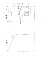
- Figure 1 shows the outer housing shape of the video game machine 1 and Figure 2 shows the corresponding front view.
- the control armature 3 In the upper part of the video game machine 1 there is a loudspeaker 2 and in the middle part the control armature 3 with a program selector switch 4, two game buttons 5 and a game lever 6.
- the lower part of the device receives a coin machine which is not the subject of the invention.
- Figures 3 and 4 correspond to Figures 1 and 2, but they show in section the arrangement and design of the monitor or screen 8. This is fixed with an annular frame 9 and between the frame 9 and the screen 8, a wooden panel 10 is attached.
- the ring-shaped frame 9 is rotatably mounted on rollers 11, 12, 13 and 14 and a motor 15, which is designed as a geared motor, has a rubber pressure roller 16, which ensures transmission of the rotational forces.
- the rubber pressure roller transmits its rotational force to the annular frame 9 and the screen 8 carries out a pivoting movement through an angle of 90 °, so that it is his Changes position from IIoch to landscape or vice versa.
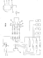
- FIG. 5 shows the electrical circuit of the video game machine 1 for automatically executing a pivoting movement of the screen 8 in its image plane through an angle of 90 ° with the aid of the motor 15 and its drive roller 16.
- the circuit shown here is described for simplification with relays.
- Corresponding semiconductor switching elements and microprocessors can of course also be used.
- program boards 17, 18, 19 and 20 are used, which are designed as plug-in boards in a manner known per se.
- a larger number of program boards can also be used.
- Each board contains its own game program and each game program has the appropriate position of the screen 8, namely a portrait or landscape format.
- Each program board 17, 18, 19 and 20 is equipped with its own power supply 21, 22, 23, and 24. From the program boards 17, 18, 19 and 20, electrical lines lead to a distributor circuit 25, which merges function lines of the same type.
- Each program board 17, 18, 19 and 20 is also assigned a row of switches 26, 27, 28 and 29, which is electrically connected to the distributor circuit 25 and to the program selector switch 4.
- the switch row 26 includes the switches or relays 30 and 31; to switch row 27, switches or relays 32 and 33; to switch row 28, switches or relays 34 and 35, and to switch row 29, switches or relays 36 and 37.
- Each row of switches is protected against reverse currents by a diode 40 or 41, or 42 or 43.
- a position of the screen 8 is assigned to each relay 38 or 39, i.e. For example, when the relay 38 is energized, it turns on the motor 15 and it assumes the predetermined position. The same applies to the relay 39. Between these relays 38 and 39 and the motor 15 there is a conventional interference filter.
- Each switch group 26, 27, 28 and 29 is assigned to a motor relay 38 or 39 in accordance with the associated program.
- the operator sets the desired game.
- the corresponding program board for example the program board 17
- the associated switch row 26 is excited with the further relays 30 and 31.
- the motor relay 38 thus switches through and the motor 15 assumes the position which is assigned to this motor relay 38.
- the relays 26, 30 and 31 also ensure that all video functions or video signal channels of the selected program board are switched to the monitor or screen separately from the video functions or video channels of the other program boards. These include, for example, four channels for the four geometric directions of the cursor, which are controlled by the game lever 6, three color channels, one synchronizing signal channel and two or four audio signal channels. If the program selector switch is switched to another program, a corresponding process takes place as described.
Abstract
Description
- Die Erfindung betrifft einen Videoautomat, insbesondere Video-Spielautomat, bestehend aus einem Gehäuse, in dem sich eine Bedienungsarmatur, mindestens ein Lautsprecher und mindestens eine Bildröhre sowie eine elektronische und elektrische Schaltung und gegebenenfalls ein Münzautomat befinden, wobei die Bildröhre in ihrer Bildebene mittels eines Motors drehbar gelagert ist.
- Mit der fortschreitenden Entwicklung der Bildschirmgeräte und insbesondere der Mikroprozessortechnik wurden auch für Zwecke beispielsweise der Unterhaltung und der Ausbildung komplizierte Programme entwickelt, welche bestimmte Abläufe als Simulation von möglichen Ereignissen darstellen. Derartige Geräte finden als Simulatoren Anwendung, beispielswweise in Fahrschulen, Pilotenschulen oder dergleichen.
- Auch für Unterhaltungszwepke werden die Spielprogramme aufwendiger, da auch der Verbraucher zunehmend höhere Ansprüche stellt. So besteht das Bedürfnis nach beipielsweise nicht nur umfangreicheren Spielen, sondern der Verbraucher wünscht auch eine Vielzahl verschiedener Programme, so daß der Unterhaltungswert damit auch gesteigert wird.
- Um diesem Bedürfnis abzuhelfen, wurden bereits Video-Spielautomaten entwickelt, welche mit unterschiedlichen Programmen geladen werden, die sich der Verbraucher auswählen kann.
- Die ursprünglich entwickelte Braunsche Röhre, welche die Basis eines Monitors bildet, weist eine runde Bildschirmform auf, jedoch wurden insbesondere zu Zwecken der Fernsehtechnik Bildschirmröhren hergestellt, welche eine ovale oder eine nahezu rechteckförmige Ausbildung mit unterschiedlichen Kantenlängen aufweisen, wobei der Bildschirm im Querformat verwendet wird. Die überwiegende Zahl aller Ereignisse finden in der Ebene statt oder lassen sich in der Ebene darstellen, so daß sich hierfür das Querformat am besten eignet.
- Für Spezialzwecke wurden Bildschirme entwickelt, welche ein Hochformat aufweisen, beispielsweise für Personalcomputer, die überwiegend für Schreibprogramme eingesetzt werden. Auf diese Weise läßt sich auf dem Bildschirm bequem eine DIN A4-Seite wiedergeben.
- Insbesondere bei Spielprogrammen finden sich solche, die im Hochformat darzustellen sind, wie beipielsweise Raumfahrtspiele, während eine andere Gruppe von Spielen sich besser für eine Darstellung im Querformat eignet. Bisher hat man dieses Problem so gelöst, daß für jede Spielgruppe unterschiedliche Geräte verwendet werden. Die Geräte selbst werden jedoch ebenfalls aufwendiger und damit auch teurer und wenn beispielsweise ein Restaurant eine möglichst große Variation von Spielen anbieten will, so ist es erforderlich, mindestens zwei Geräte aufzustellen. Hieraus ergibt sich ferner ein Platzproblem.
- Der Erfindung liegt somit die Aufgabe zugrunde, hier Abhilfe zu schaffen und ein Gerät vorzuschlagen, welches in der Lage ist, Videoprogramme sowohl im Hoch- als auch im Querformat wiedergeben zu können, ohne daß seitens des Spielers irgendwelche Manipulationen erforderlich sind oder die Spielprogramme ein entsprechendes Steuerprogramm aufweisen.
- Die Lösung dieser Aufgabe erfolgt dadurch, daß bei dem eingangs genannten Videoautomaten die Bildröhre mit Hilfe eines ansteuerbaren Motors entsprechend der einstellbaren Position eines Programmwahlschalters und einer dadurch bewirkten Ansteuerung einer entsprechend zugeordneten Schaltergruppe und dem damit ausgewählten Programm (Spiel) in die diesem Programm entsprechende Position bringbar ist und die Bildröhre mit einem ringförmigen, auf Rollen gelagerten und in der Bildebene liegenden, drehbaren Rahmen mittels einer auf den äußeren Rand des Rahmens einwirkbaren Andruckrolle des ansteuerbaren Getriebemotors drehbar ausgebildet ist.
- Durch die Auswahl eines Programmes erfolgt gemäß der Erfindung automatisch die Einstellung einer Position des Bildschirmformates im Hoch- oder Querformat, welche durch das ausgewählte Programm bedingt wird. Die Bedienungsperson hat auf diese Positionierung - bis auf die Programmauswahl - keinen Einfluß.
- Der Winkel der Schwenkbewegung des ringförmigen Rahmens beträgt 90°, so daß dadurch die Umpositionierung vom Hochin ein Querformat oder umgekehrt gegeben ist.
- In Weiterbildung der Erfindung weist der äußere Rand des Rahmens zur Endpositionierung seiner Schwenkbewegung Anschläge auf, welche auf den Antriebsmotor einwirkbar angeordnet sind. Auf diese Weise wird der Motor bei Erreichen seiner Endposition automatisch abgeschaltet.
- Nach der Erfindung sind sämtliche Video-Steuerfunktionen eines mittels einer Programmplatine festgelegten und durch Betätigung eines Programmwahlschalters auswählbaren Programmes (Spieles) und einer dadurch bewirkten Ansteuerung einer entsprechend zugeordneten Schaltergruppe der Bildröhre zuführbar. Jede Schaltergruppe beaufschlagt in vorteilhafter Weise einen ihr zugeordneten und mit dem Motor verbundenen Motorpositionsschalter, welcher seinerseits jeweils den Motor ansteuert.
- Jeder Programmplatine ist nach der Erfindung eine Schaltergruppe zugeordnet, weche mit Hilfe des Programmwahlschalters ansteuerbar ist.
- In vorteilhafter Weise sind mehrere Schaltergruppen einem Motorpositionsschhalter zugeordnet und jeder Motorpositionsschalter beaufschlagt bei Erregung den Motor, derart, daß die Bildröhre die dem Motorpositionsschalter zugeordnete Position einnimmt.
- Die Erfindung wird anhand der Zeichnung näher erläutert. Hierbei zeigen:
- FIGUR 1 eine Seitenansicht eines Video-Spielautomaten;
- FIGUR 2 eine Frontansicht eines Video-Spielautomaten;
- FIGUR 3 eine Seitenansicht eines Video-Spielautomaten im Schnitt;
- FIGUR 4 eine Frontansicht eines Video-Spielautomaten im Schnitt, und
- FIGUR 5 eine Schaltung eines Video-Spielautomaten in schematischer Darstellung.
- Die Figur 1 zeigt die äußere Gehäuseform des Video-Spielautomaten 1 und die Figur 2 die entsprechende Frontansicht. Im oberen Teil des VideoSpielautomaten 1 befindet sich ein Lautsprecher 2 und im mittleren Teil die Bedienungsarmatur 3 mit einem Programmwahlschalter 4, zwei Spielknöpfen 5 und einem Spielhebel 6. Der untere Teil des Gerätes nimmt einen Münzautomaten auf, welcher nicht Gegenstand der , Erfindung ist.
- Die Figuren 3 und 4 entsprechen den Figuren 1 und 2, jedoch zeigen sie im Schnitt die Anordnung und Ausbildung des Monitors oder Bildschirmes 8. Dieser ist mit einem ringförmigen Rahmen 9 befestigt und zwischen dem Rahmen 9 und dem Bildschirm 8 ist eine Holzverkleidung 10 angebracht. Der ringförmige Rahmen 9 ist auf Rollen 11, 12, 13 und 14 drehbar gelagert und ein Motor 15, welcher als Getriebemotor ausgebildet ist, weist eine Gummiandruckrolle 16 auf, welche für eine Übertragung der Drehkräfte sorgt.
- Wird der Motor 15 mit einer Spannung beaufschlagt, wie noch später anhand der Figur 5 näher erläutert wird, so überträgt die Gummiandruckrolle ihre Drehkraft auf den ringförmigen Rahmen 9 und der Bildschirm 8 führt eine Schwenkbewegung um einen Winkel von 90° aus, so daß er seine Position von einem IIoch- in ein Querformat oder umgekehrt ändert.
- Die Figur 5 zeigt die elektrische Schaltung des Video-Spielautomaten 1 zur automatischen Durchführung einer Schwenkbewegung des Bildschirmes 8 in seiner Bildebene um einen Winkel von 90° mit Hilfe des Motors 15 und seiner Antriebsrolle 16. Die hier dargestellte Schaltung wird zur Vereinfachung mit Relais beschrieben. Es können natürlich auch entsprechende Halbleiterschaltelemente und Mikroprozessoren verwendet werden.
- In dem hier beschriebenen Beispiel werden vier Programmplatinen 17, 18, 19 und 20 verwendet, welche in an sich bekannter Weise als Steckplatinen ausgebildet sind. Es kann auch eine größere Zahl von Programplatinen verwendet werden. Jede Platine enthält ein eigenes Spielprogramm und jedem Spielprogramm ist die geeignete Lageposition des Bildschirmes 8, nämlich ein Hoch- oder ein Querformat vorgegeben.
- Jede Programmplatine 17, 18, 19 und 20 ist mit einer eigenen Energieversorgung 21, 22, 23, und 24 ausgerüstet. Von den Programmplatinen 17, 18, 19 und 20 führen elektrische Leitungen zu einer Verteilerschaltung 25, welche gleichartige Funktionsleitungen zusammenführt.
- Jeder Programmplatine 17, 18, 19 und 20 ist ferner eine Schalterreihe 26, 27, 28 und 29 zugeordnet, welche mit der Verteilerschaltung 25 und mit dem Programmwahlschalter 4 elektrisch verbunden ist. Zur Schalterreihe 26 gehören die Schalter oder Relais 30 und 31; zur Schalterreihe 27 die Schalter oder Relais 32 und 33; zur Schalterreihe 28 die Schalter oder Relais 34 und 35, und zur Schalterreihe 29 die Schalter oder Relais 36 und 37. Jede Schalterreihe ist durch eine Diode 40 bzw. 41, bzw.42 bzw. 43 gegen Rückströme abgesichert. Den Schalterreihen schließen ich Motorrelais 38 und 39 an. Jedem Relais 38 oder 39 ist eine Position des Bildschirmes 8 zugeordnet, d.h. wenn zum Beispiel das Relais 38 erregt wird, schaltet es den Motor 15 an und dieser nimmt die vorbestimmte Position ein. Entsprechendes gilt für das Relais 39. Zwischen diesen Relais 38 und 39 und dem Motor 15 liegt ein konventionelles Entstörfilter.
- Jede Schaltergruppe 26, 27, 28 und 29 ist entsprechend dem zugehörigen Programm einem Motorrelais 38 oder 39 zugeordnet.
- Mit dem Programmwahlschalter 4 stellt die Bedienungsperson das gewünschte Spiel ein. Hierdurch wird die entsprechende Programmplatine, beispielsweise die Programmplatine 17 angesteuert und die dazugehörige Schalterreihe 26 mit den weiteren Relais 30 und 31 erregt. Das Motorrelais 38 schaltet damit durch und der Motor 15 nimmt die Position ein, welche diesem Motorrelais 38 zugeordnet ist.
- Die Relais 26, 30 und 31 sorgen ferner dafür, daß sämtliche Videofunktionen bzw. Videosignalkanäle der ausgewählten Programmplatine getrennt von den Videofunktionen bzw. bzw. Videokanälen der anderen Programmplatinen auf den Monitor bzw. Bildschirm geschaltet werden. Hierzu zählen beispielsweise vier Kanäle für die vier geometrischen Richtungen des Cursors, welche durch den Spielhebel 6 gesteuert werden, drei Farbkanäle, ein Synchronsignal-Kanal und zwei oder vier Tonsignal-Kanäle. Wird der Programmwahlschalter auf ein anderes Programm geschaltet läuft ein entsprechender Vorgang, wie beschrieben, ab.
Claims (6)
Applications Claiming Priority (2)
| Application Number | Priority Date | Filing Date | Title |
|---|---|---|---|
| DE19863601813 DE3601813A1 (de) | 1986-01-22 | 1986-01-22 | Videoautomat |
| DE3601813 | 1986-01-22 |
Publications (2)
| Publication Number | Publication Date |
|---|---|
| EP0230291A2 true EP0230291A2 (de) | 1987-07-29 |
| EP0230291A3 EP0230291A3 (en) | 1990-05-30 |
Family
ID=6292371
Family Applications (1)
| Application Number | Title | Priority Date | Filing Date |
|---|---|---|---|
| EP87100574A Ceased EP0230291A3 (en) | 1986-01-22 | 1987-01-17 | Automatic video-game |
Country Status (3)
| Country | Link |
|---|---|
| US (1) | US4848744A (de) |
| EP (1) | EP0230291A3 (de) |
| DE (1) | DE3601813A1 (de) |
Cited By (3)
| Publication number | Priority date | Publication date | Assignee | Title |
|---|---|---|---|---|
| FR2679783A1 (fr) * | 1991-08-01 | 1993-02-05 | Sega Sa | Systeme de commutation et controle de quatre plaques de jeux video. |
| EP0544155A1 (de) * | 1991-11-25 | 1993-06-02 | Nsm Aktiengesellschaft | Schwenkbare Bildschirmröhre für Video-Spielgeräte |
| EP0546477A1 (de) * | 1991-12-07 | 1993-06-16 | Tecmo Kabushiki Kaisha | Einbaubildschirm |
Families Citing this family (33)
| Publication number | Priority date | Publication date | Assignee | Title |
|---|---|---|---|---|
| US4969647A (en) * | 1989-06-02 | 1990-11-13 | Atari Corporation | Invertible hand-held electronic game apparatus |
| JPH053968A (ja) * | 1991-06-25 | 1993-01-14 | Pioneer Electron Corp | 映像表示、及びその表示に連動する運動装置 |
| DE9108178U1 (de) * | 1991-07-03 | 1991-10-24 | Linhart, Jirka, 5223 Nuembrecht, De | |
| US5750592A (en) * | 1992-08-04 | 1998-05-12 | Seiko Epson Corporation | Ink composition for ink jet recording |
| DE19512513C2 (de) * | 1995-03-14 | 1997-11-20 | Nsm Ag | Verfahren zum Betreiben eines Spiel- und/oder Unterhaltungsgeräts |
| US7063615B2 (en) * | 1995-06-29 | 2006-06-20 | Igt | Electronic gaming apparatus with authentication |
| USRE39369E1 (en) | 1995-06-29 | 2006-10-31 | Igt | Electronic casino gaming system with improved play capacity, authentication and security |
| US6620047B1 (en) | 1995-06-29 | 2003-09-16 | Igt | Electronic gaming apparatus having authentication data sets |
| US5643086A (en) | 1995-06-29 | 1997-07-01 | Silicon Gaming, Inc. | Electronic casino gaming apparatus with improved play capacity, authentication and security |
| DE19542625C2 (de) * | 1995-08-21 | 1998-02-12 | Nsm Ag | Geldspielgerät |
| US5859990A (en) * | 1995-12-29 | 1999-01-12 | Intel Corporation | System for transferring data segments from a first storage device to a second storage device using an alignment stage including even and odd temporary devices |
| AU778786B2 (en) * | 1996-06-28 | 2004-12-23 | Igt | Improved electronic gaming apparatus |
| AU779999B2 (en) * | 1996-06-28 | 2005-02-24 | Igt | Improved electronic gaming apparatus |
| AU768482B2 (en) * | 1996-06-28 | 2003-12-11 | Igt | Improved electronic gaming apparatus |
| US20020025852A1 (en) * | 2000-09-29 | 2002-02-28 | Alcorn Allan E. | Gaming apparatus with portrait-mode display |
| US20050255924A1 (en) * | 2000-03-03 | 2005-11-17 | Cole Joseph W | Gaming apparatus having door mounted display |
| CA2402389A1 (en) | 2000-03-08 | 2002-09-19 | Shuffle Master, Inc. | Computerized gaming system, method and apparatus |
| US7988559B2 (en) | 2001-03-08 | 2011-08-02 | Igt | Computerized gaming system, method and apparatus |
| US7043641B1 (en) * | 2000-03-08 | 2006-05-09 | Igt | Encryption in a secure computerized gaming system |
| US20020006828A1 (en) * | 2000-07-14 | 2002-01-17 | Quasimoto | Arcade style video game adapter system |
| WO2002015998A2 (en) * | 2000-08-21 | 2002-02-28 | International Game Technology | Method and apparatus for software authentication |
| CA2356015A1 (en) | 2000-08-31 | 2002-02-28 | International Game Technology | Method and apparatus for encoding vouchers in a cashless casino gaming system |
| US7203841B2 (en) | 2001-03-08 | 2007-04-10 | Igt | Encryption in a secure computerized gaming system |
| US7162036B2 (en) | 2001-08-06 | 2007-01-09 | Igt | Digital identification of unique game characteristics |
| US6685567B2 (en) * | 2001-08-08 | 2004-02-03 | Igt | Process verification |
| CA2460046C (en) | 2001-09-10 | 2014-06-10 | Igt | Method for developing gaming programs compatible with a computerized gaming operating system and apparatus |
| US6902481B2 (en) | 2001-09-28 | 2005-06-07 | Igt | Decoupling of the graphical presentation of a game from the presentation logic |
| US7931533B2 (en) | 2001-09-28 | 2011-04-26 | Igt | Game development architecture that decouples the game logic from the graphics logics |
| US20030064784A1 (en) * | 2001-09-28 | 2003-04-03 | William Wells | Wide screen gaming apparatus |
| US8708828B2 (en) | 2001-09-28 | 2014-04-29 | Igt | Pluggable modular gaming modifiers and configuration templates for gaming environments |
| WO2003045519A1 (en) * | 2001-11-26 | 2003-06-05 | Igt | Pass-through live validation device and method |
| US20040228266A1 (en) * | 2003-05-14 | 2004-11-18 | Knight Kenneth Kingston | Digital animation disk |
| GB201506325D0 (en) * | 2015-04-14 | 2015-05-27 | Johnson Matthey Plc | Shaped catalyst particle |
Citations (4)
| Publication number | Priority date | Publication date | Assignee | Title |
|---|---|---|---|---|
| FR2542543A1 (fr) * | 1983-03-08 | 1984-09-14 | Pierre Sa Rene | Dispositif de rotation d'un tube cathodique avec dispositif de positionnement angulaire et verrouillage |
| DE3309367A1 (de) * | 1983-03-16 | 1984-09-20 | Stan Peter 8700 Würzburg Dabrowski | Elektronisches muenzbetaetigtes tv-spielgeraet fuer universellen einsatz von computerspielprogrammen |
| DE8427491U1 (de) * | 1984-09-19 | 1985-02-28 | Botta Automaten, 4500 Osnabrück | Videospielgeraet |
| DE3347156A1 (de) * | 1983-12-27 | 1985-07-11 | Paul 4992 Espelkamp Gauselmann | Vorrichtung zur befestigung einer bildschirmroehre in einem bildschirm-spielgeraet |
Family Cites Families (4)
| Publication number | Priority date | Publication date | Assignee | Title |
|---|---|---|---|---|
| US4352492A (en) * | 1976-08-23 | 1982-10-05 | Fairchild Camera & Instrument Corp. | Data storage apparatus |
| JPS5877785U (ja) * | 1981-11-24 | 1983-05-26 | 株式会社シグマ | モニタ−ゲ−ム機 |
| US4500060A (en) * | 1982-06-11 | 1985-02-19 | Westinghouse Electric Corp. | Swivel-tilt platform |
| DE3301880A1 (de) * | 1983-01-21 | 1984-09-13 | Geiger-Automatenbau GmbH, 8980 Oberstdorf | Video-autorennspiel |
-
1986
- 1986-01-22 DE DE19863601813 patent/DE3601813A1/de active Granted
-
1987
- 1987-01-17 EP EP87100574A patent/EP0230291A3/de not_active Ceased
- 1987-01-21 US US07/005,709 patent/US4848744A/en not_active Expired - Fee Related
Patent Citations (4)
| Publication number | Priority date | Publication date | Assignee | Title |
|---|---|---|---|---|
| FR2542543A1 (fr) * | 1983-03-08 | 1984-09-14 | Pierre Sa Rene | Dispositif de rotation d'un tube cathodique avec dispositif de positionnement angulaire et verrouillage |
| DE3309367A1 (de) * | 1983-03-16 | 1984-09-20 | Stan Peter 8700 Würzburg Dabrowski | Elektronisches muenzbetaetigtes tv-spielgeraet fuer universellen einsatz von computerspielprogrammen |
| DE3347156A1 (de) * | 1983-12-27 | 1985-07-11 | Paul 4992 Espelkamp Gauselmann | Vorrichtung zur befestigung einer bildschirmroehre in einem bildschirm-spielgeraet |
| DE8427491U1 (de) * | 1984-09-19 | 1985-02-28 | Botta Automaten, 4500 Osnabrück | Videospielgeraet |
Cited By (4)
| Publication number | Priority date | Publication date | Assignee | Title |
|---|---|---|---|---|
| US6337720B1 (en) | 1991-07-12 | 2002-01-08 | Tecmo Kabushiki Kaisha | Built-in monitor apparatus |
| FR2679783A1 (fr) * | 1991-08-01 | 1993-02-05 | Sega Sa | Systeme de commutation et controle de quatre plaques de jeux video. |
| EP0544155A1 (de) * | 1991-11-25 | 1993-06-02 | Nsm Aktiengesellschaft | Schwenkbare Bildschirmröhre für Video-Spielgeräte |
| EP0546477A1 (de) * | 1991-12-07 | 1993-06-16 | Tecmo Kabushiki Kaisha | Einbaubildschirm |
Also Published As
| Publication number | Publication date |
|---|---|
| DE3601813A1 (de) | 1987-07-23 |
| EP0230291A3 (en) | 1990-05-30 |
| DE3601813C2 (de) | 1989-12-21 |
| US4848744A (en) | 1989-07-18 |
Similar Documents
| Publication | Publication Date | Title |
|---|---|---|
| DE3601813C2 (de) | ||
| DE60104402T2 (de) | Bedienungsvorrichtung und zugehöriges verfahren zur modulation des ausgangssignals | |
| DE60009803T2 (de) | Mehrrichtungsschalter und Betätigungsvorrichtung | |
| DE60224669T2 (de) | Graphische benutzerschnittstelle | |
| DE2613435A1 (de) | Fernsehempfaenger mit einer zusatzeinrichtung zur darstellung von spielsymbolen auf dem bildschirm | |
| DE2819713C3 (de) | Hilfstastenfeld | |
| EP0623040B1 (de) | Unterhaltungs-anlage | |
| DE60215882T2 (de) | Handeingabevorrichtung | |
| DE112011102040B4 (de) | Kraftsteuermodul zur steuerung einer kraft und verfahren zum steuern einer kraft | |
| DE602004002503T2 (de) | Digitales Mischpult | |
| EP1202565B1 (de) | Bildschirmanzeigeeinrichtung | |
| DE102013108260A1 (de) | Elektronische Vorrichtung | |
| DE3315025A1 (de) | Spielvorrichtung | |
| EP0321772B1 (de) | Schachlehrcomputer | |
| DE19625954A1 (de) | Bediengerät für eine Produktionseinheit eines Fernsehstudios oder eines Fernseh-Übertragungswagens | |
| DE3229634C2 (de) | ||
| DE3019432A1 (de) | Elektronikspielplatte | |
| DE3339796C2 (de) | ||
| DE10118015A1 (de) | Elektromotorischer Möbelantrieb zum Verstellen von Teilen eines Möbels relativ zueinander | |
| EP0950315A1 (de) | Spielgerät für unterhaltungsshow | |
| DE3432169A1 (de) | Videospieleinrichtung | |
| DE3816488C2 (de) | ||
| DE2827075C2 (de) | Handapparat für die Bedienung elektronisch steuerbarer Geräte | |
| DE3208136C2 (de) | ||
| DE102014115759A1 (de) | Lichtmischpult |
Legal Events
| Date | Code | Title | Description |
|---|---|---|---|
| PUAI | Public reference made under article 153(3) epc to a published international application that has entered the european phase |
Free format text: ORIGINAL CODE: 0009012 |
|
| AK | Designated contracting states |
Kind code of ref document: A2 Designated state(s): AT BE CH DE ES FR GB GR IT LI LU NL SE |
|
| PUAL | Search report despatched |
Free format text: ORIGINAL CODE: 0009013 |
|
| AK | Designated contracting states |
Kind code of ref document: A3 Designated state(s): AT BE CH DE ES FR GB GR IT LI LU NL SE |
|
| 17P | Request for examination filed |
Effective date: 19900917 |
|
| 17Q | First examination report despatched |
Effective date: 19911206 |
|
| STAA | Information on the status of an ep patent application or granted ep patent |
Free format text: STATUS: THE APPLICATION HAS BEEN REFUSED |
|
| 18R | Application refused |
Effective date: 19930911 |