EP0232864A2 - Reinforced Therapeutic Tube - Google Patents
Reinforced Therapeutic Tube Download PDFInfo
- Publication number
- EP0232864A2 EP0232864A2 EP87101634A EP87101634A EP0232864A2 EP 0232864 A2 EP0232864 A2 EP 0232864A2 EP 87101634 A EP87101634 A EP 87101634A EP 87101634 A EP87101634 A EP 87101634A EP 0232864 A2 EP0232864 A2 EP 0232864A2
- Authority
- EP
- European Patent Office
- Prior art keywords
- tube
- reinforced
- therapeutic
- reinforcing material
- reinforced therapeutic
- Prior art date
- Legal status (The legal status is an assumption and is not a legal conclusion. Google has not performed a legal analysis and makes no representation as to the accuracy of the status listed.)
- Granted
Links
Images


Classifications
-
- A—HUMAN NECESSITIES
- A61—MEDICAL OR VETERINARY SCIENCE; HYGIENE
- A61M—DEVICES FOR INTRODUCING MEDIA INTO, OR ONTO, THE BODY; DEVICES FOR TRANSDUCING BODY MEDIA OR FOR TAKING MEDIA FROM THE BODY; DEVICES FOR PRODUCING OR ENDING SLEEP OR STUPOR
- A61M16/00—Devices for influencing the respiratory system of patients by gas treatment, e.g. mouth-to-mouth respiration; Tracheal tubes
- A61M16/04—Tracheal tubes
- A61M16/0402—Special features for tracheal tubes not otherwise provided for
- A61M16/0425—Metal tubes
-
- A—HUMAN NECESSITIES
- A61—MEDICAL OR VETERINARY SCIENCE; HYGIENE
- A61M—DEVICES FOR INTRODUCING MEDIA INTO, OR ONTO, THE BODY; DEVICES FOR TRANSDUCING BODY MEDIA OR FOR TAKING MEDIA FROM THE BODY; DEVICES FOR PRODUCING OR ENDING SLEEP OR STUPOR
- A61M16/00—Devices for influencing the respiratory system of patients by gas treatment, e.g. mouth-to-mouth respiration; Tracheal tubes
- A61M16/04—Tracheal tubes
- A61M16/0434—Cuffs
Definitions
- the present invention relates to reinforced therapeutic tubes of various types for use in the fields of anesthesia and respiratory control, etc., such as catheters, oral and nasal endotracheal tubes, tracheal cannulae, etc., and particularly pertains to reinforced therapeutic tubes with a spiral shape reinforcing material embedded into the wall of the tube body, which are excellent in kink resistance, pressure resistance and flexibility.
- Such therapeutic tubes are required to have flexibility and thin wall.
- to make the flow rate of fluid adequate by making the wall thin is quite opposite to make the tube difficult to collapse.
- the thinner the tube wall the larger the hazard of the tube collapsing. Should a tube collapse and be blockaded, while in use, it would bring serious trouble or even death to the patient who is using it. For this reason, such a therapeutic tube must be of a structure which would not be blockaded, even if bent with a small radius.
- a tube having such a reinforcing material embedded into the tube wall in spiral form tended to expand its ID at both ends of the tube body owing to the repelling force of the spiral shape reinforcing material under external force; accordingly, when the tube wall was thin, the tip of the reinforcing wire broke through and projected out of the tube wall, thereby injuring the tracheal inner wall.
- a flat wire is spirally embedded in the tube wall. This makes for easy welding of wire, but the welded part swells up, and because of the wire being flat, flexibility is poor, thus posing problems.
- An object of this invention is to provide smooth surfaced thin reinforced therapeutic tube, which is safe, with no strain arising near the tube end parts, thus no reinforcing material tip projecting out of the tube wall, by positively preventing the recoiling of the tip of the spiral shape reinforcing material, which occurs when external force is imposed on the tube or in the like events.
- Another object of this invention is to provide reinforced therapeutic tube excellent in kink resistance, pressure resistance and flexibility.
- Still another object of this invention is to provide reinforced therapeutic tubes excellent in blockading resistance, such that it will not be blockaded, even if bent with small radii.
- a reinforced therapeutic tube axially integrally formed of a tube body with a reinforcing material spirally embedded into the tube wall and at least one of tubular parts where no spiral reinforcing material exists, in which at least one end of the spiral shape reinforcing material is bent inward of the tube to a length such that it is engaged onto at least a neighboring spiral turn, and moreover, at least its tip of the reinforcing material bent is buried in the tube wall.
- the materials for use in therapeutic tube of this invention there may be mentioned polyvinyl chloride, polyurethane, polyurethane urea, silicone rubber, fluororubber or other materials having equivalent initial tensile resistivity to theirs.
- segmented polyurethane consisting of soft segment and hard segment has high biocompatibility, and excells in the modulus of elongation elasticity; therefore, it is preferable as an elastomer for thin, small bore catheter.
- the tube body with a reinforcing material spirally embedded into the tube wall and at least one of tubular parts where no spiral reinforcing material exists are integrally formed in its axial direction.
- the tube is composed so as to have flexibility.
- the tubular parts may be integrally formed at both ends of the tube body, one of which may be an accepter.
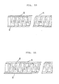
- the tip end of the reinforcing material which is wound in spiral shape is bent parallel to the inside surface of the tube and inward of the tube for a length of at least one or more pitches of the spiral, preferably 1 - 30mm, more preferably 2 - l0mm, and moreover, at least the tip of the reinforcing material bent is buried into the inside wall of the tube.
- the possibility of the tip of the reinforcing material breaking through the tube wall is readily and positively preventable by such a device as hereabove described. If the tube-inward bending back of the spiral end were short, and it were not engaged onto the neighboring turn of the spiral, however, the spiral tip sometimes might break through the tube wall; it is for this reason necessary that the end of the spiral should be bent back to a length longer than at least one neighboring pitch of the spiral, and the end of the reinforcing material securely engaged onto the neighboring turn of the spiral. According to this invention, since as described hereabove, the spiral end bent inward of the tube is always engaged onto the neighboring turn of the spiral because of the tendency of the spiral to expand its diameter; therefore, the spiral tip will never break through said tube wall.
- metal wires normally having initial tensile resistivity higher than 1 ⁇ 104 kg-f/mm2
- various synthetic fibers such as vinylon, acrylic fibers, polysulfone, vinylidene, polyurethane, polyethylene, polypropylene, nylon, aromatic polyamide (aramid), polyesters such as polyethylene terephthalate, polybutylene terephthalate, aromatic polyesters (arylate), etc.
- tungsten wire having a high initial tensile resistivity, is preferably used.
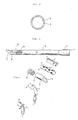
- FIG. 1 is a perspective view showing a blood removing and sending catheter for extracorporeal circulation of blood in cardiotomy, lung assist, etc.;
- FIG. 2 a view of A - A section of FIG. 1; and
- FIG. 3, a side view of said catheter.
- Said catheter l is composed of tubular part 2, accepter 3 and tube body 4 which connects them.
- the catheter has a hollow 5 formed through the whole length thereof.
- a spiral shape reinforcing material 6 is embedded in its wall, but no reinforcing material exists in the tubular part 2 and the accepter 3.
- the catheter 1 is so composed as to have flexibility, using polyvinyl chloride, polyurethane, polyurethane urea, silicone rubber, fluororubber or other materials having equivalent initial tensile resistivity to theirs.
- segmented polyurethane consisting of soft segment and hard segment has high biocompatibility, and excells in the modulus of elongation elasticity; therefore, it is preferable as an elastomer for thin, small bore catheter.
- a spiral shape reinforcing material 6 is embedded in the tube wall.
- This spiral shape reinforcing material 6 is made of a wire with a diameter 0.02 - 1.0mm, preferably, 0.05 - 0.4 mm, and with a pitch 0.l - 4 mm.
- the tip end 9 of the reinforcing material 6 is bent back inward of the tube to a length such that it is engaged onto at least a neighboring spiral turn, as shown in FIG. 3,5, l0 and ll. At least the tip 9 of said bent back reinforcing material 6 is buried in the tube inner wall, to be directly in contact with the neighboring spiral turn owing to its repelling force. If the elasticity of the tube is large, the end of the reinforcing material is in contact with the neighboring spiral turn through the compressed thin tube inner wall.
- At least the tip end 9 of the reinforcing material 6 may be completely buried into the tube wall by coating the inside surface of the tube with an elastomer solution. This sometimes produce some swell on the tube inside surface, but this swell is in a gentle hill shape, posing no practical problem at all.
- the accepter 3 of the catheter 1 is provided with a joint (not shown in drawings). Since normally, the ID of the proximal end 7 of the accepter 3 is made larger than the ID of the tube body 4, the wall surface of accepter 3 of catheter l is slightly expanded, as the end of the joint is inserted, whereby the joint is secured on the catheter 1.
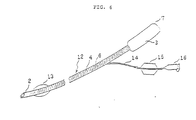
- FIG. 6 is a perspective view of an endotracheal tube, being an embodiment of the reinforced therapeutic tube of this invention, showing that the ID of the accepter 3 is equal to the ID of the tube body 4, or is somewhat enlarged therefrom toward its proximal end 7. Irregularities on the inside surface of said accepter, if any, would undesirably give rise to pooling of secretions, when sucking them and so on; for this reason, the connection of the accepter to the tube body should desirably be finished as smooth as possible.
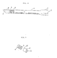
- FIG. 7 is an endotracheal tube bent at a radius of curve (R) of 100 - 180mm, illustrating an endotracheal tube with its opening positioned on the upper surface side, when it is placed in a shape of a waxing moon with its tip end on the the left.
- R radius of curve
- the tubular part 2 of the catheter 1 or the endotracheal tube 12 shall be connected with the tube body 4 of the catheter smoothly both on the in- and out-side surfaces, to be integrated therewith, and shall have no reinforcing material therein.
- This tubular part 2 should desirably be properly rounded at the end opening so as not to injure the living body, when the catheter is inserted thereinto.
- more than one side hole 8 may be provided through the wall surface of the tip end.
- Such catheters 1 may be formed with various sizes. Normally, many of them have overall lengths of 5 - 100cm, preferably l0 - 45cm; ID 0.2 - 20mm, preferably 2 - l2mm; and wall thicknesses 0.2 - l.5mm.
- Endotracheal tubes should have overall lengths of 5 - 50cm, preferably l5 - 35cm;ID 0.2 - 20mm, preferably 2 - 8mm; wall thicknesses 0.l5 - l.5mm, lengths of the tubular part 2 l - 20mm, preferably 2 - l0mm; and lengths of accepter 3 l0 - 50mm, preferably l5 - 25mm.
- a so-called cuff l3 as a means for securing hermetic sealing between the tube and the tracheal may be provided at a distance of 5mm, preferably l0mm or longer, from the tip.
- the therapeutic tube of this invention may be manufactured in the following manner: First, a thin wall core-tube is made by extruding or by coating a solution of elastomer on a mandrel, followed by drying; Next, the reinforcing material is wound in spiral shape by a fixed pitch on the core-tube thus obtained. After that, an elastomer of the same quality with the core- tube or an elastomer of the different quality from the core-tube, extruded by use of an extruder, or a solution of elastomer is coated on the surface of the core-tube thus obtained.
- the tube obtained after drying is cut to a length such that it will have the intended length, when the tubular part 2 and the accepter 3, having no spiral shape reinforcing material, are integrally formed. Then, at least one end of the reinforcing material of the tube thus cut is drawn out from the elastomer part, or taken out by cutting off the elastomer; the end of the reinforcing material is bent inward of the tube by means of a pincette etc., and thereafter, a solution of elastomer is coated on the reinforcing material part bent inward of the tube, followed by drying. In that way, the tube body 4 is formed.
- the tubular parts in which no reinforcing material is contained are normally formed separately from the tube body 4 as a tubular single unit having a hollow portion 11 therein by making use of a well-known forming technique such as injection molding etc., as shown in FIG. 4 and 9, after which it is bonded or fused to the tube body by any well-known method.
- metal powder is contained in the portion l0 of the tubular part 2 which is to be brought in contact with the tube body 4, so that the portion containing the metal powder is to be molten by induction heating, causing the tubular part 2 to be joined with the tube body 4.
- the tubular part 2 is formed of the same material as the tube body 4, or when it needs to be formed of a material softer or harder than the tube body 4, different materials may be used.
- the external surface of the connection between the tube body 4 and the tubular part 2 may be formed in smooth state.
- To make the external surface of the connection smooth is important to facilitate insertion and removal of the catheter into and out of the living body.
- an elastomer solution on the internal surface of the connection between the tube body 4 and the tubular part 2, it is possible to make the internal surface side of the connection smooth. Then by bringing the internal surface of the connection into a smooth state, thrombosis, settling and pooling of secretions and contaminants, and settling of body fluids may be prevented.
- the accepter 3 is connected to the tube body 4 by the similar method as the tubular part 2.
- the end of the spiral shape reinforcing material on the accepter side of the tube body should desirably be bent inward of the tube to a length such that it is engaged onto a neighboring spiral turn, and moreover, at least the bent tip is buried into the tube wall, or buried into the accepter side. If the wall of the accepter is so thick that the tip of the reinforcing material may not break through the wall, such treatment may be dispensed with.
Abstract
Description
- The present invention relates to reinforced therapeutic tubes of various types for use in the fields of anesthesia and respiratory control, etc., such as catheters, oral and nasal endotracheal tubes, tracheal cannulae, etc., and particularly pertains to reinforced therapeutic tubes with a spiral shape reinforcing material embedded into the wall of the tube body, which are excellent in kink resistance, pressure resistance and flexibility.
- Heretofore, for therapeutic tubes for bringing fluids into and out of living body, various types have been proposed. The simplest one of them all is catheter. For therapeutic tubes having more complex structures than catheters, there are available endotracheal tubes, tracheal cannulae and various tubes for drainage, etc.
- Such therapeutic tubes are required to have flexibility and thin wall. However, to make the flow rate of fluid adequate by making the wall thin is quite opposite to make the tube difficult to collapse. The thinner the tube wall, the larger the hazard of the tube collapsing. Should a tube collapse and be blockaded, while in use, it would bring serious trouble or even death to the patient who is using it. For this reason, such a therapeutic tube must be of a structure which would not be blockaded, even if bent with a small radius.
- Recently, proposals have been made to spirally embedded into the tube wall a reinforcing material such as stainless steel wire or piano wire, etc., being in wire form or one in thin plate form with narrow width, to provide such a therapeutic tube with resistance to blockading (Japanese Patent Application Laid-Open No.38565/l983, etc.) Such a therapeutic tube having a spiral shape reinforcing material inside the tube wall is called "reinforced tube".
- However, a tube having such a reinforcing material embedded into the tube wall in spiral form tended to expand its ID at both ends of the tube body owing to the repelling force of the spiral shape reinforcing material under external force; accordingly, when the tube wall was thin, the tip of the reinforcing wire broke through and projected out of the tube wall, thereby injuring the tracheal inner wall. As a method for preventing this, it has been proposed to fix by welding the tip of the spiral wire onto a neighboring spiral wire turn, but because the wire is fine, the welding is technically difficult; even if the welding has been successfully made, strain will develop in the weld, moreover, the welded part will thickly swell up, possibly causing breakage of thin tube wall.
- As an example of solving the above mentioned problem, a flat wire is spirally embedded in the tube wall. This makes for easy welding of wire, but the welded part swells up, and because of the wire being flat, flexibility is poor, thus posing problems.
- An object of this invention is to provide smooth surfaced thin reinforced therapeutic tube, which is safe, with no strain arising near the tube end parts, thus no reinforcing material tip projecting out of the tube wall, by positively preventing the recoiling of the tip of the spiral shape reinforcing material, which occurs when external force is imposed on the tube or in the like events.
- Another object of this invention is to provide reinforced therapeutic tube excellent in kink resistance, pressure resistance and flexibility.
- Still another object of this invention is to provide reinforced therapeutic tubes excellent in blockading resistance, such that it will not be blockaded, even if bent with small radii.
- These objects may be achieved by providing a reinforced therapeutic tube axially integrally formed of a tube body with a reinforcing material spirally embedded into the tube wall and at least one of tubular parts where no spiral reinforcing material exists, in which at least one end of the spiral shape reinforcing material is bent inward of the tube to a length such that it is engaged onto at least a neighboring spiral turn, and moreover, at least its tip of the reinforcing material bent is buried in the tube wall.
-
- FIG. 1 is a perspective view of an example of the reinforced therapeutic tube of this invention;
- FIG. 2 is a view of A - A section of FIG. 1;
- FIG. 3 is a side view of the tube of FIG. 1;
- FIG.4 is a perspective view showing examples of the tubular part for being joined to the tube body;
- FIG. 5 is a side view showing another mode of the reinforced therapeutic tube of this invention;
- FIG. 6 is a perspective view of an endotracheal tube, being one of reinforced therapeutic tube of this invention;
- FIG. 7 is a perspective view of an endotracheal tube bent in a shape of a waxing moon at a radius of curve (R) with its forward end placed on the left side, being an example of reinforced therapeutic tube of this invention;
- FIG. 8 is a side view of another endotracheal tube of this invention;
- FIG.9 is a perspective view showing an example of the tubular part which is used in manufacturing the therapeutic tube of this invention;
- FIGS. 10 and 11 are side views showing other modes of the therapeutic tube of this invention; in the former, the forward end of the reinforcing material is brought back to the other end, and in the latter, it is wound back at a pitch larger than that of the outside spiral.
- 1 ...
Catheter 2 ...Tubular part 3 ... Accepter 4 ...Tube body 5 ... Hollow 6 ... Reinforcingmaterial 7 ...Proximal end 8 ...Side hole 9 ... Tip end of reinforcingmaterial 10 ... Portion of the tubular part in contact withtube body 11 ... Hollow 12 ...Endotracheal tube 13 ...Cuff 14 ...Pilot tube 15...Pilot balloon 16 ... Luer connector - The materials for use in therapeutic tube of this invention, there may be mentioned polyvinyl chloride, polyurethane, polyurethane urea, silicone rubber, fluororubber or other materials having equivalent initial tensile resistivity to theirs. Of these materials, segmented polyurethane consisting of soft segment and hard segment has high biocompatibility, and excells in the modulus of elongation elasticity; therefore, it is preferable as an elastomer for thin, small bore catheter.
- In the reinforced therapeutic tube of this invention, the tube body with a reinforcing material spirally embedded into the tube wall and at least one of tubular parts where no spiral reinforcing material exists are integrally formed in its axial direction. In this embodiment, the tube is composed so as to have flexibility.
- The tubular parts may be integrally formed at both ends of the tube body, one of which may be an accepter.
- In the reinforced therapeutic tube of this invention, the tip end of the reinforcing material which is wound in spiral shape is bent parallel to the inside surface of the tube and inward of the tube for a length of at least one or more pitches of the spiral, preferably 1 - 30mm, more preferably 2 - l0mm, and moreover, at least the tip of the reinforcing material bent is buried into the inside wall of the tube.
- According to this invention, the possibility of the tip of the reinforcing material breaking through the tube wall is readily and positively preventable by such a device as hereabove described. If the tube-inward bending back of the spiral end were short, and it were not engaged onto the neighboring turn of the spiral, however, the spiral tip sometimes might break through the tube wall; it is for this reason necessary that the end of the spiral should be bent back to a length longer than at least one neighboring pitch of the spiral, and the end of the reinforcing material securely engaged onto the neighboring turn of the spiral. According to this invention, since as described hereabove, the spiral end bent inward of the tube is always engaged onto the neighboring turn of the spiral because of the tendency of the spiral to expand its diameter; therefore, the spiral tip will never break through said tube wall.
- As reinforcing materials for use in therapeutic tubes of this invention, there may be mentioned metal wires normally having initial tensile resistivity higher than 1 × 10⁴ kg-f/mm², such as steel wire, stainless steel wire, tungsten wire, etc., various synthetic fibers such as vinylon, acrylic fibers, polysulfone, vinylidene, polyurethane, polyethylene, polypropylene, nylon, aromatic polyamide (aramid), polyesters such as polyethylene terephthalate, polybutylene terephthalate, aromatic polyesters (arylate), etc., and besides, protein fibers and carbon fibers, etc. Of these reinforcing materials, tungsten wire, having a high initial tensile resistivity, is preferably used.
- In the following, preferred embodiments of the reinforced therapeutic tube of this invention are described with reference to the accompanying drawings, but this invention will not be limited to these embodiments only. FIG. 1 is a perspective view showing a blood removing and sending catheter for extracorporeal circulation of blood in cardiotomy, lung assist, etc.; FIG. 2, a view of A - A section of FIG. 1; and FIG. 3, a side view of said catheter.
- Said catheter l is composed of
tubular part 2,accepter 3 andtube body 4 which connects them. The catheter has a hollow 5 formed through the whole length thereof. Along thetube body 4 of the catheter, a spiralshape reinforcing material 6 is embedded in its wall, but no reinforcing material exists in thetubular part 2 and theaccepter 3. In this embodiment, the catheter 1 is so composed as to have flexibility, using polyvinyl chloride, polyurethane, polyurethane urea, silicone rubber, fluororubber or other materials having equivalent initial tensile resistivity to theirs. Of these materials, segmented polyurethane consisting of soft segment and hard segment has high biocompatibility, and excells in the modulus of elongation elasticity; therefore, it is preferable as an elastomer for thin, small bore catheter. Along thetube body 4 of the catheter l, a spiralshape reinforcing material 6 is embedded in the tube wall. This spiralshape reinforcing material 6 is made of a wire with a diameter 0.02 - 1.0mm, preferably, 0.05 - 0.4 mm, and with a pitch 0.l - 4 mm. - Lest the tip of the spiral
shape reinforcing material 6 should break through the tube wall, before joining thetubular part 2 to the tube body, thetip end 9 of the reinforcingmaterial 6 is bent back inward of the tube to a length such that it is engaged onto at least a neighboring spiral turn, as shown in FIG. 3,5, l0 and ll. At least thetip 9 of said bentback reinforcing material 6 is buried in the tube inner wall, to be directly in contact with the neighboring spiral turn owing to its repelling force. If the elasticity of the tube is large, the end of the reinforcing material is in contact with the neighboring spiral turn through the compressed thin tube inner wall. - At least the
tip end 9 of the reinforcingmaterial 6 may be completely buried into the tube wall by coating the inside surface of the tube with an elastomer solution. This sometimes produce some swell on the tube inside surface, but this swell is in a gentle hill shape, posing no practical problem at all. Theaccepter 3 of the catheter 1 is provided with a joint (not shown in drawings). Since normally, the ID of theproximal end 7 of theaccepter 3 is made larger than the ID of thetube body 4, the wall surface ofaccepter 3 of catheter l is slightly expanded, as the end of the joint is inserted, whereby the joint is secured on the catheter 1. - FIG. 6 is a perspective view of an endotracheal tube, being an embodiment of the reinforced therapeutic tube of this invention, showing that the ID of the
accepter 3 is equal to the ID of thetube body 4, or is somewhat enlarged therefrom toward itsproximal end 7. Irregularities on the inside surface of said accepter, if any, would undesirably give rise to pooling of secretions, when sucking them and so on; for this reason, the connection of the accepter to the tube body should desirably be finished as smooth as possible. - FIG. 7 is an endotracheal tube bent at a radius of curve (R) of 100 - 180mm, illustrating an endotracheal tube with its opening positioned on the upper surface side, when it is placed in a shape of a waxing moon with its tip end on the the left.
- The
tubular part 2 of the catheter 1 or theendotracheal tube 12 shall be connected with thetube body 4 of the catheter smoothly both on the in- and out-side surfaces, to be integrated therewith, and shall have no reinforcing material therein. Thistubular part 2 should desirably be properly rounded at the end opening so as not to injure the living body, when the catheter is inserted thereinto. And for prevention of blockading of the tip end opening, more than oneside hole 8 may be provided through the wall surface of the tip end. - Such catheters 1 may be formed with various sizes. Normally, many of them have overall lengths of 5 - 100cm, preferably l0 - 45cm; ID 0.2 - 20mm, preferably 2 - l2mm; and wall thicknesses 0.2 - l.5mm.
- Endotracheal tubes should have overall lengths of 5 - 50cm, preferably l5 - 35cm;ID 0.2 - 20mm, preferably 2 - 8mm; wall thicknesses 0.l5 - l.5mm, lengths of the tubular part 2 l - 20mm, preferably 2 - l0mm; and lengths of
accepter 3 l0 - 50mm, preferably l5 - 25mm. And as desired, a so-called cuff l3 as a means for securing hermetic sealing between the tube and the tracheal may be provided at a distance of 5mm, preferably l0mm or longer, from the tip. It is no matter whether any side hole is provided or not, but for an endotracheal tube of which tubular part end is beveled, as shown in FIG. 6 and 8, it is desirable to provide a side hole of a size smaller than 80% of the tubular part ID on the opposite side to the bevel. - The therapeutic tube of this invention may be manufactured in the following manner: First, a thin wall core-tube is made by extruding or by coating a solution of elastomer on a mandrel, followed by drying; Next, the reinforcing material is wound in spiral shape by a fixed pitch on the core-tube thus obtained. After that, an elastomer of the same quality with the core- tube or an elastomer of the different quality from the core-tube, extruded by use of an extruder, or a solution of elastomer is coated on the surface of the core-tube thus obtained. The tube obtained after drying is cut to a length such that it will have the intended length, when the
tubular part 2 and theaccepter 3, having no spiral shape reinforcing material, are integrally formed. Then, at least one end of the reinforcing material of the tube thus cut is drawn out from the elastomer part, or taken out by cutting off the elastomer; the end of the reinforcing material is bent inward of the tube by means of a pincette etc., and thereafter, a solution of elastomer is coated on the reinforcing material part bent inward of the tube, followed by drying. In that way, thetube body 4 is formed. - The tubular parts in which no reinforcing material is contained are normally formed separately from the
tube body 4 as a tubular single unit having ahollow portion 11 therein by making use of a well-known forming technique such as injection molding etc., as shown in FIG. 4 and 9, after which it is bonded or fused to the tube body by any well-known method. For example, metal powder is contained in the portion l0 of thetubular part 2 which is to be brought in contact with thetube body 4, so that the portion containing the metal powder is to be molten by induction heating, causing thetubular part 2 to be joined with thetube body 4. Thetubular part 2 is formed of the same material as thetube body 4, or when it needs to be formed of a material softer or harder than thetube body 4, different materials may be used. - By the method hereabove mentioned, the external surface of the connection between the
tube body 4 and thetubular part 2 may be formed in smooth state. To make the external surface of the connection smooth is important to facilitate insertion and removal of the catheter into and out of the living body. Further, by coating an elastomer solution on the internal surface of the connection between thetube body 4 and thetubular part 2, it is possible to make the internal surface side of the connection smooth. Then by bringing the internal surface of the connection into a smooth state, thrombosis, settling and pooling of secretions and contaminants, and settling of body fluids may be prevented. - The
accepter 3 is connected to thetube body 4 by the similar method as thetubular part 2. At this instance also, the end of the spiral shape reinforcing material on the accepter side of the tube body should desirably be bent inward of the tube to a length such that it is engaged onto a neighboring spiral turn, and moreover, at least the bent tip is buried into the tube wall, or buried into the accepter side. If the wall of the accepter is so thick that the tip of the reinforcing material may not break through the wall, such treatment may be dispensed with.
Claims (21)
Applications Claiming Priority (4)
| Application Number | Priority Date | Filing Date | Title |
|---|---|---|---|
| JP1702786 | 1986-02-07 | ||
| JP17027/86 | 1986-02-07 | ||
| JP1986133075U JPH025799Y2 (en) | 1986-02-07 | 1986-08-29 | |
| JP133075/86 | 1986-08-29 |
Publications (3)
| Publication Number | Publication Date |
|---|---|
| EP0232864A2 true EP0232864A2 (en) | 1987-08-19 |
| EP0232864A3 EP0232864A3 (en) | 1990-05-30 |
| EP0232864B1 EP0232864B1 (en) | 1994-05-04 |
Family
ID=26353483
Family Applications (1)
| Application Number | Title | Priority Date | Filing Date |
|---|---|---|---|
| EP87101634A Expired - Lifetime EP0232864B1 (en) | 1986-02-07 | 1987-02-06 | Reinforced Therapeutic Tube |
Country Status (5)
| Country | Link |
|---|---|
| US (1) | US4737153A (en) |
| EP (1) | EP0232864B1 (en) |
| JP (1) | JPH025799Y2 (en) |
| CA (1) | CA1288066C (en) |
| DE (1) | DE3789716T2 (en) |
Cited By (23)
| Publication number | Priority date | Publication date | Assignee | Title |
|---|---|---|---|---|
| EP0339501A2 (en) * | 1988-04-26 | 1989-11-02 | Arturo Dr. Muti | Bronchial examination catheter |
| EP0393834A2 (en) * | 1989-03-16 | 1990-10-24 | Samuel Shiber | Rotary catheter for atherectomy system |
| AU621008B2 (en) * | 1989-09-25 | 1992-02-27 | Schneider (Usa) Inc. | Small diameter dilatation catheter having wire reinforced coaxial tubular body |
| WO1995001813A1 (en) * | 1993-07-06 | 1995-01-19 | The Government Of The United States Of America, Represented By The Secretary, Department Of Health And Human Services | Endotracheal tubes |
| WO1995009665A1 (en) * | 1993-10-06 | 1995-04-13 | WILLY RüSCH AG | Inflatable instrument for natural and/or artificial body cavities |
| US5537729A (en) * | 1991-09-12 | 1996-07-23 | The United States Of America As Represented By The Secretary Of The Department Of Health And Human Services | Method of making ultra thin walled wire reinforced endotracheal tubing |
| US5711296A (en) * | 1991-09-12 | 1998-01-27 | The United States Of America As Represented By The Department Of Health And Human Services | Continuous positive airway pressure system |
| WO2009019470A1 (en) * | 2007-08-09 | 2009-02-12 | Glysure Ltd | Sensing apparatus |
| US10589050B2 (en) | 2012-11-14 | 2020-03-17 | Fisher & Paykel Healthcare Limited | Zone heating for respiratory circuits |
| US10751498B2 (en) | 2014-03-17 | 2020-08-25 | Fisher & Paykel Healthcare Limited | Medical tubes for respiratory systems |
| US10814091B2 (en) | 2013-10-24 | 2020-10-27 | Fisher & Paykel Healthcare Limited | System for delivery of respiratory gases |
| US10828482B2 (en) | 2013-12-20 | 2020-11-10 | Fisher & Paykel Healthcare Limited | Humidification system connections |
| EP3049138B1 (en) * | 2013-09-23 | 2020-12-09 | Naga Wire-Tracking Tracheal Tube Pty Ltd | Endotracheal tube |
| US10960167B2 (en) | 2015-09-09 | 2021-03-30 | Fisher & Paykel Healthcare Limited | Zone heating for respiratory circuits |
| US10974015B2 (en) | 2012-03-15 | 2021-04-13 | Fisher & Paykel Healthcare Limited | Respiratory gas humidification system |
| US11058844B2 (en) | 2012-12-04 | 2021-07-13 | Fisher & Paykel Healthcare Limited | Medical tubes and methods of manufacture |
| US11129956B2 (en) | 2012-04-27 | 2021-09-28 | Fisher & Paykel Healthcare Limited | Usability features for respiratory humidification system |
| US11311695B2 (en) | 2016-12-22 | 2022-04-26 | Fisher & Paykel Healthcare Limited | Medical tubes and methods of manufacture |
| US11324911B2 (en) | 2014-06-03 | 2022-05-10 | Fisher & Paykel Healthcare Limited | Flow mixers for respiratory therapy systems |
| US11351332B2 (en) | 2016-12-07 | 2022-06-07 | Fisher & Paykel Healthcare Limited | Sensing arrangements for medical devices |
| RU2777931C2 (en) * | 2011-06-03 | 2022-08-11 | Фишер Энд Пейкел Хелткэа Лимитед | Medical tubes and their manufacturing methods |
| US11559653B2 (en) | 2014-02-07 | 2023-01-24 | Fisher & Paykel Healthcare Limited | Respiratory humidification system |
| US11801360B2 (en) | 2013-09-13 | 2023-10-31 | Fisher & Paykel Healthcare Limited | Connections for humidification system |
Families Citing this family (189)
| Publication number | Priority date | Publication date | Assignee | Title |
|---|---|---|---|---|
| US4819634A (en) * | 1984-05-14 | 1989-04-11 | Surgical Systems & Instruments | Rotary-catheter for atherectomy system |
| JPH01121065A (en) * | 1987-11-05 | 1989-05-12 | Terumo Corp | Medical tube and its preparation |
| AU2807389A (en) * | 1987-12-07 | 1989-07-05 | Nimbus Medical, Inc. | Inflow cannula for intravascular blood pumps |
| US5061256A (en) * | 1987-12-07 | 1991-10-29 | Johnson & Johnson | Inflow cannula for intravascular blood pumps |
| US4967744A (en) * | 1988-11-03 | 1990-11-06 | Airoflex Medical, Inc. | Flexible breathing circuit |
| US4985022A (en) * | 1988-11-23 | 1991-01-15 | Med Institute, Inc. | Catheter having durable and flexible segments |
| US5044369A (en) * | 1989-01-23 | 1991-09-03 | Harvinder Sahota | Bent topless catheters |
| US4986279A (en) * | 1989-03-01 | 1991-01-22 | National-Standard Company | Localization needle assembly with reinforced needle assembly |
| CA2016178A1 (en) * | 1989-05-08 | 1990-11-08 | Rodney G. Wolff | Ptca catheter |
| US4955862A (en) * | 1989-05-22 | 1990-09-11 | Target Therapeutics, Inc. | Catheter and catheter/guide wire device |
| US5248305A (en) * | 1989-08-04 | 1993-09-28 | Cordis Corporation | Extruded tubing and catheters having helical liquid crystal fibrils |
| US5156785A (en) * | 1991-07-10 | 1992-10-20 | Cordis Corporation | Extruded tubing and catheters having increased rotational stiffness |
| DE3930770A1 (en) * | 1989-09-14 | 1991-03-28 | Wolfgang F Dr Schoener | IMPLANTABLE CATHETERS MADE FROM MEDICAL COMPATIBLE ELASTIC PLASTIC |
| JPH087867Y2 (en) * | 1989-10-26 | 1996-03-06 | 韶夫 成毛 | Double lumen endotracheal tube |
| US5313957A (en) * | 1990-01-05 | 1994-05-24 | Medamicus, Inc. | Guide wire mounted pressure transducer |
| US5147315A (en) * | 1990-04-06 | 1992-09-15 | C. R. Bard, Inc. | Access catheter and system for use in the female reproductive system |
| US4990143A (en) * | 1990-04-09 | 1991-02-05 | Sheridan Catheter Corporation | Reinforced medico-surgical tubes |
| US5122125A (en) * | 1990-04-25 | 1992-06-16 | Ashridge A.G. | Catheter for angioplasty with soft centering tip |
| US5279596A (en) * | 1990-07-27 | 1994-01-18 | Cordis Corporation | Intravascular catheter with kink resistant tip |
| US5190520A (en) * | 1990-10-10 | 1993-03-02 | Strato Medical Corporation | Reinforced multiple lumen catheter |
| WO1992021398A1 (en) * | 1991-06-07 | 1992-12-10 | Taut, Incorporated | Uncollapsible catheter and methods |
| US5344413A (en) * | 1991-06-28 | 1994-09-06 | C. R. Bard, Inc. | Catheter having a tip connector for rapid catheter exchanges |
| US5222949A (en) * | 1991-07-23 | 1993-06-29 | Intermed, Inc. | Flexible, noncollapsible catheter tube with hard and soft regions |
| EP0600940B1 (en) * | 1991-07-24 | 1999-02-24 | Advanced Cardiovascular Systems, Inc. | Low profile perfusion-type dilatation catheter |
| US5630806A (en) * | 1991-08-13 | 1997-05-20 | Hudson International Conductors | Spiral wrapped medical tubing |
| CA2071760A1 (en) * | 1991-09-23 | 1993-03-24 | Alexander Ureche | Infusion sleeve for surgical ultrasonic apparatus |
| AU655323B2 (en) * | 1991-10-04 | 1994-12-15 | Ethicon Inc. | Flexible trocar tube |
| US6808520B1 (en) * | 1991-12-13 | 2004-10-26 | Endovascular Technologies, Inc. | Dual valve, flexible expandable sheath and method |
| GB9225014D0 (en) * | 1992-11-30 | 1993-01-20 | Univ Hospital London Dev Corp | Pulse injector for quantitative angiographic blood-flow measurements |
| US5643174A (en) * | 1993-08-18 | 1997-07-01 | Sumitomo Bakelite Company Limited | Endoscopic guide tube with embedded coil spring |
| US5405338A (en) * | 1993-08-19 | 1995-04-11 | Cordis Corporation | Helically wound catheters |
| US5370617A (en) * | 1993-09-17 | 1994-12-06 | Sahota; Harvinder | Blood perfusion balloon catheter |
| US5405316A (en) * | 1993-11-17 | 1995-04-11 | Magram; Gary | Cerebrospinal fluid shunt |
| US5571073A (en) * | 1994-01-28 | 1996-11-05 | Cordis Corporation | Catheter flexible tip assembly |
| US5902290A (en) * | 1994-03-14 | 1999-05-11 | Advanced Cardiovascular Systems, Inc. | Catheter providing intraluminal access |
| US5607407A (en) * | 1994-05-09 | 1997-03-04 | Tolkoff; Marc J. | Catheter assembly |
| US5492114A (en) * | 1994-08-22 | 1996-02-20 | Vroman; Holly | Non-rebreathing oxygen mask |
| US5667499A (en) * | 1994-10-04 | 1997-09-16 | Scimed Life Systems, Inc. | Guide catheter unibody |
| US5658264A (en) * | 1994-11-10 | 1997-08-19 | Target Therapeutics, Inc. | High performance spiral-wound catheter |
| JP4408958B2 (en) * | 1995-02-28 | 2010-02-03 | ボストン サイエンティフィック コーポレーション | Medical instruments |
| US6824553B1 (en) | 1995-04-28 | 2004-11-30 | Target Therapeutics, Inc. | High performance braided catheter |
| US5891112A (en) * | 1995-04-28 | 1999-04-06 | Target Therapeutics, Inc. | High performance superelastic alloy braid reinforced catheter |
| US5702373A (en) * | 1995-08-31 | 1997-12-30 | Target Therapeutics, Inc. | Composite super-elastic alloy braid reinforced catheter |
| WO1996033763A2 (en) * | 1995-04-28 | 1996-10-31 | Target Therapeutics, Inc. | High performance braided catheter |
| JPH11506369A (en) * | 1995-06-01 | 1999-06-08 | サイムド ライフ システム インコーポレイテッド | Liquid flow propulsion catheter |
| US5647848A (en) * | 1995-06-07 | 1997-07-15 | Meadox Medicals, Inc. | High strength low compliance composite balloon for balloon catheters |
| US20030069522A1 (en) * | 1995-12-07 | 2003-04-10 | Jacobsen Stephen J. | Slotted medical device |
| US5776115A (en) * | 1996-01-17 | 1998-07-07 | Becton Dickinson And Company | Catheter having a gear-shaped lumen to avert the elimination of fluid flow therein |
| US6440088B1 (en) * | 1996-05-24 | 2002-08-27 | Precision Vascular Systems, Inc. | Hybrid catheter guide wire apparatus and method |
| US5899892A (en) * | 1996-05-31 | 1999-05-04 | Scimed Life Systems, Inc. | Catheter having distal fiber braid |
| US5827242A (en) * | 1996-06-21 | 1998-10-27 | Medtronic, Inc. | Reinforced catheter body and method for its fabrication |
| US6240964B1 (en) * | 1996-07-01 | 2001-06-05 | Dayco Products, Inc. | Energy attenuation device for a fluid conveying line and method of attenuating energy in such a line |
| US6125890A (en) * | 1996-07-01 | 2000-10-03 | Dayco Products, Inc. | Energy attenuation device for a fluid-conveying line and method of attenuating energy in such a line |
| US5971975A (en) * | 1996-10-09 | 1999-10-26 | Target Therapeutics, Inc. | Guide catheter with enhanced guidewire tracking |
| US6159187A (en) * | 1996-12-06 | 2000-12-12 | Target Therapeutics, Inc. | Reinforced catheter with a formable distal tip |
| US5800393A (en) * | 1997-03-07 | 1998-09-01 | Sahota; Harvinder | Wire perfusion catheter |
| US5951514A (en) * | 1997-03-07 | 1999-09-14 | Sahota; Harvinder | Multi-lobe perfusion balloon |
| US5951539A (en) * | 1997-06-10 | 1999-09-14 | Target Therpeutics, Inc. | Optimized high performance multiple coil spiral-wound vascular catheter |
| US6152912A (en) * | 1997-06-10 | 2000-11-28 | Target Therapeutics, Inc. | Optimized high performance spiral-wound vascular catheter |
| US5947940A (en) * | 1997-06-23 | 1999-09-07 | Beisel; Robert F. | Catheter reinforced to prevent luminal collapse and tensile failure thereof |
| US5891114A (en) * | 1997-09-30 | 1999-04-06 | Target Therapeutics, Inc. | Soft-tip high performance braided catheter |
| US6217566B1 (en) | 1997-10-02 | 2001-04-17 | Target Therapeutics, Inc. | Peripheral vascular delivery catheter |
| US7007718B2 (en) * | 1997-11-24 | 2006-03-07 | Dayco Products, Llc | Energy attenuation apparatus for a conduit conveying liquid under pressure, system incorporating same, and method of attenuating energy in a conduit |
| US20080053547A1 (en) * | 1997-11-24 | 2008-03-06 | Yungrwei Chen | Energy attenuation apparatus for a conduit conveying liquid under pressure, system incorporating same, and method of attenuating energy in a conduit |
| US7380572B2 (en) * | 1997-11-24 | 2008-06-03 | Fluid Routing Solutions, Inc. | Energy attenuation apparatus for a conduit conveying liquid under pressure, system incorporating same, and method of attenuating energy in a conduit |
| US6130406A (en) * | 1998-01-08 | 2000-10-10 | Adam Spence Corporation | Method for forming a medical tubing device |
| US6171235B1 (en) | 1998-05-29 | 2001-01-09 | Circon Corporation | Flexible pressure resistant cover for the articulation system of a medical instrument |
| US6702972B1 (en) | 1998-06-09 | 2004-03-09 | Diametrics Medical Limited | Method of making a kink-resistant catheter |
| US6193705B1 (en) | 1998-10-28 | 2001-02-27 | Scimed Life Systems, Inc. | Flow assisted catheter |
| US6742545B2 (en) * | 1998-12-21 | 2004-06-01 | Parker-Hannifin Corporation | Hose construction |
| US20010016730A1 (en) * | 1999-02-17 | 2001-08-23 | Harold M. Martins | Apparatus for the dialysis of blood, method for fabricating the same, and method for the dialysis of blood |
| US6648854B1 (en) | 1999-05-14 | 2003-11-18 | Scimed Life Systems, Inc. | Single lumen balloon-tipped micro catheter with reinforced shaft |
| US6689120B1 (en) | 1999-08-06 | 2004-02-10 | Boston Scientific Scimed, Inc. | Reduced profile delivery system |
| US7655016B2 (en) * | 1999-09-17 | 2010-02-02 | Covidien | Mechanical pump for removal of fragmented matter and methods of manufacture and use |
| AU1548901A (en) * | 1999-11-25 | 2001-06-04 | Sumitomo Bakelite Company Limited | Guide tube and application method therefor |
| US7036530B2 (en) * | 1999-12-22 | 2006-05-02 | Dayco Products, Llc | Energy attenuation device for a fluid-conveying line and method of attenuating energy in such a line |
| WO2002007618A1 (en) * | 2000-07-21 | 2002-01-31 | Atropos Limited | A cannula |
| US6669886B1 (en) | 2000-08-03 | 2003-12-30 | Scimed Life Systems, Inc. | Reinforced catheter and method of manufacture |
| US6620149B1 (en) * | 2000-10-05 | 2003-09-16 | Scimed Life Systems, Inc. | Corewire securement system |
| US6616651B1 (en) | 2000-11-17 | 2003-09-09 | Robert C. Stevens | Intravascular microcatheter with embedded helical coil reinforcement member and methods and apparatus for making same |
| US6800055B2 (en) | 2001-02-21 | 2004-10-05 | Cordis Corporation | Low attenuating radioactive seeds |
| AU2002238147A1 (en) * | 2001-03-01 | 2002-09-19 | David A. Watson | Ingrowth preventing indwelling catheter assembly |
| US6669621B2 (en) | 2001-03-14 | 2003-12-30 | Cordis Corporation | Method and assembly for containing radioactive materials |
| US6497646B1 (en) | 2001-03-14 | 2002-12-24 | Cordis Corporation | Intravascular radiotherapy source ribbon having variable radiopacity |
| EP1401526B1 (en) * | 2001-07-05 | 2006-12-06 | Precision Vascular Systems, Inc. | Troqueable soft tip medical device and method for shaping it |
| US6877512B2 (en) * | 2001-09-05 | 2005-04-12 | The Regents Of The University Of California | Airway device |
| US20030191453A1 (en) * | 2002-04-03 | 2003-10-09 | Velez Omar E. | Catheter assembly |
| US20030195524A1 (en) * | 2002-04-12 | 2003-10-16 | Gil Barner | Body tissue aspiration cannula |
| US7048728B2 (en) * | 2002-04-26 | 2006-05-23 | Witham Richard N | Noninvasive medical instrument |
| US20030216642A1 (en) * | 2002-05-16 | 2003-11-20 | Pepin Henry J. | Radiopaque and MRI compatible catheter braid |
| US7914467B2 (en) * | 2002-07-25 | 2011-03-29 | Boston Scientific Scimed, Inc. | Tubular member having tapered transition for use in a medical device |
| EP1545680B1 (en) | 2002-07-25 | 2010-09-08 | Boston Scientific Limited | Medical device for navigation through anatomy |
| US7381196B2 (en) * | 2002-08-23 | 2008-06-03 | Miller Nicholas M | Vacuum venous assist cannula |
| US8377035B2 (en) | 2003-01-17 | 2013-02-19 | Boston Scientific Scimed, Inc. | Unbalanced reinforcement members for medical device |
| US7169118B2 (en) | 2003-02-26 | 2007-01-30 | Scimed Life Systems, Inc. | Elongate medical device with distal cap |
| US20040167437A1 (en) * | 2003-02-26 | 2004-08-26 | Sharrow James S. | Articulating intracorporal medical device |
| US6896671B2 (en) * | 2003-03-12 | 2005-05-24 | Arrow International, Inc. | Catheter with limited longitudinal extension |
| US7001369B2 (en) | 2003-03-27 | 2006-02-21 | Scimed Life Systems, Inc. | Medical device |
| AU2004229523B2 (en) * | 2003-04-14 | 2008-09-25 | Cook Medical Technologies Llc | Large diameter delivery catheter/sheath |
| ATE378085T1 (en) * | 2003-04-28 | 2007-11-15 | Cook Inc | FLEXIBLE INTRODUCER WITH DIFFERENT DUROMETER |
| US20040260271A1 (en) * | 2003-06-18 | 2004-12-23 | Huyser Richard F. | Extended fenestration catheter with internal coil and method of making the same |
| US7824392B2 (en) | 2003-08-20 | 2010-11-02 | Boston Scientific Scimed, Inc. | Catheter with thin-walled braid |
| US7615043B2 (en) * | 2003-08-20 | 2009-11-10 | Boston Scientific Scimed, Inc. | Medical device incorporating a polymer blend |
| US7955313B2 (en) * | 2003-12-17 | 2011-06-07 | Boston Scientific Scimed, Inc. | Composite catheter braid |
| US7824345B2 (en) | 2003-12-22 | 2010-11-02 | Boston Scientific Scimed, Inc. | Medical device with push force limiter |
| US7505881B2 (en) * | 2004-09-11 | 2009-03-17 | The Board Of Trustees Of The Leland Stanford Junior University | Method and apparatus for modeling the modal properties of optical waveguides |
| AU2005302021A1 (en) * | 2004-11-01 | 2006-05-11 | Applied Medical Resources Corporation | Longitudinal sheath enforcement |
| US20060111649A1 (en) * | 2004-11-19 | 2006-05-25 | Scimed Life Systems, Inc. | Catheter having improved torque response and curve retention |
| US7815599B2 (en) * | 2004-12-10 | 2010-10-19 | Boston Scientific Scimed, Inc. | Catheter having an ultra soft tip and methods for making the same |
| US7918227B1 (en) * | 2005-07-28 | 2011-04-05 | Phythyon Eve K | Endotracheal tube |
| US9445784B2 (en) * | 2005-09-22 | 2016-09-20 | Boston Scientific Scimed, Inc | Intravascular ultrasound catheter |
| US7850623B2 (en) * | 2005-10-27 | 2010-12-14 | Boston Scientific Scimed, Inc. | Elongate medical device with continuous reinforcement member |
| US7249613B1 (en) | 2006-02-03 | 2007-07-31 | Dayco Products, Llc | Energy attenuation device |
| US7717135B2 (en) * | 2006-02-03 | 2010-05-18 | Yh America, Inc. | Energy attenuation device |
| US20070208300A1 (en) * | 2006-03-01 | 2007-09-06 | Applied Medical Resources Corporation | Gas insufflation and suction/irrigation tubing |
| US7905877B1 (en) | 2006-05-12 | 2011-03-15 | Micrus Design Technology, Inc. | Double helix reinforced catheter |
| US20080058764A1 (en) * | 2006-08-29 | 2008-03-06 | Majercak David C | Catheter Tip Configuration for Improved Crossability and Trackability |
| CA2663319A1 (en) * | 2006-09-13 | 2008-03-20 | Boston Scientific Limited | Crossing guidewire |
| US20080108974A1 (en) * | 2006-10-20 | 2008-05-08 | Vital Signs, Inc. | Reinforced catheter with radiopaque distal tip and process of manufacture |
| US20080142003A1 (en) * | 2006-12-13 | 2008-06-19 | Arcadia Medical Corporation | MRI Compatible Airway Management Device |
| US8556914B2 (en) | 2006-12-15 | 2013-10-15 | Boston Scientific Scimed, Inc. | Medical device including structure for crossing an occlusion in a vessel |
| WO2008077151A1 (en) * | 2006-12-20 | 2008-06-26 | Societe De Technologie Michelin | Polyurethane |
| US20100241178A1 (en) * | 2008-06-02 | 2010-09-23 | Loma Vista Medical, Inc. | Inflatable medical devices |
| US10278682B2 (en) * | 2007-01-30 | 2019-05-07 | Loma Vista Medical, Inc. | Sheaths for medical devices |
| WO2008095052A2 (en) * | 2007-01-30 | 2008-08-07 | Loma Vista Medical, Inc., | Biological navigation device |
| EP2120680A2 (en) | 2007-02-06 | 2009-11-25 | Glumetrics, Inc. | Optical systems and methods for rationmetric measurement of blood glucose concentration |
| US20080210486A1 (en) * | 2007-03-02 | 2008-09-04 | Dayco Products, Llc | Energy attenuation device |
| US20080262474A1 (en) * | 2007-04-20 | 2008-10-23 | Boston Scientific Scimed, Inc. | Medical device |
| JP5517919B2 (en) | 2007-05-10 | 2014-06-11 | グルメトリクス、 インク. | Balanced non-consumable fluorescent sensor for immediate intravascular glucose measurement |
| US20090025724A1 (en) * | 2007-07-16 | 2009-01-29 | Herron Jr Roy Howard | System for removal of water from a hose and the hygroscopic hose utilized |
| US8409114B2 (en) * | 2007-08-02 | 2013-04-02 | Boston Scientific Scimed, Inc. | Composite elongate medical device including distal tubular member |
| US20090036832A1 (en) * | 2007-08-03 | 2009-02-05 | Boston Scientific Scimed, Inc. | Guidewires and methods for manufacturing guidewires |
| US8105246B2 (en) * | 2007-08-03 | 2012-01-31 | Boston Scientific Scimed, Inc. | Elongate medical device having enhanced torque and methods thereof |
| US20090043228A1 (en) * | 2007-08-06 | 2009-02-12 | Boston Scientific Scimed, Inc. | Laser shock peening of medical devices |
| US8821477B2 (en) * | 2007-08-06 | 2014-09-02 | Boston Scientific Scimed, Inc. | Alternative micromachined structures |
| US9808595B2 (en) * | 2007-08-07 | 2017-11-07 | Boston Scientific Scimed, Inc | Microfabricated catheter with improved bonding structure |
| US7841994B2 (en) | 2007-11-02 | 2010-11-30 | Boston Scientific Scimed, Inc. | Medical device for crossing an occlusion in a vessel |
| WO2009067626A1 (en) * | 2007-11-21 | 2009-05-28 | Glumetrics, Inc. | Use of an equilibrium intravascular sensor to achieve tight glycemic control |
| US9393375B2 (en) * | 2008-01-07 | 2016-07-19 | Mergenet Solutions | Nasal ventilation interface |
| US8376961B2 (en) | 2008-04-07 | 2013-02-19 | Boston Scientific Scimed, Inc. | Micromachined composite guidewire structure with anisotropic bending properties |
| WO2009129186A2 (en) * | 2008-04-17 | 2009-10-22 | Glumetrics, Inc. | Sensor for percutaneous intravascular deployment without an indwelling cannula |
| EP2278908B1 (en) * | 2008-04-27 | 2021-06-02 | Loma Vista Medical, Inc. | Biological navigation device |
| US8323209B2 (en) * | 2008-06-06 | 2012-12-04 | Williams Iii John | Chorionic villus sampling catheter |
| US20090320853A1 (en) * | 2008-06-27 | 2009-12-31 | Mike Kenowski | Tracheostomy Tube |
| US20100063479A1 (en) * | 2008-09-10 | 2010-03-11 | Boston Scientific Scimed, Inc. | Small profile, tubular component design and method of manufacture |
| US8535243B2 (en) * | 2008-09-10 | 2013-09-17 | Boston Scientific Scimed, Inc. | Medical devices and tapered tubular members for use in medical devices |
| US8795254B2 (en) * | 2008-12-10 | 2014-08-05 | Boston Scientific Scimed, Inc. | Medical devices with a slotted tubular member having improved stress distribution |
| US20100191168A1 (en) | 2009-01-29 | 2010-07-29 | Trustees Of Tufts College | Endovascular cerebrospinal fluid shunt |
| US20100300449A1 (en) * | 2009-05-28 | 2010-12-02 | Chan Sam C | Position Indicator for Tracheostomy Tube |
| US20100300448A1 (en) * | 2009-05-28 | 2010-12-02 | Kenowski Michael A | Tracheostomy Tube |
| US20110061658A1 (en) * | 2009-08-12 | 2011-03-17 | Robert Koorn | Oropharyngeal devices for use in ventilating patients |
| WO2011041546A1 (en) | 2009-09-30 | 2011-04-07 | Glumetrics, Inc. | Sensors with thromboresistant coating |
| US8467843B2 (en) | 2009-11-04 | 2013-06-18 | Glumetrics, Inc. | Optical sensor configuration for ratiometric correction of blood glucose measurement |
| US8137293B2 (en) | 2009-11-17 | 2012-03-20 | Boston Scientific Scimed, Inc. | Guidewires including a porous nickel-titanium alloy |
| US20110152658A1 (en) * | 2009-12-17 | 2011-06-23 | Glumetrics, Inc. | Identification of aberrant measurements of in vivo glucose concentration using temperature |
| US8641677B2 (en) * | 2010-01-21 | 2014-02-04 | James T. Rawls | Low-profile intravenous catheter device |
| JP2013523282A (en) | 2010-03-31 | 2013-06-17 | ボストン サイエンティフィック サイムド,インコーポレイテッド | Guide wire with bending stiffness profile |
| WO2012009486A2 (en) | 2010-07-13 | 2012-01-19 | Loma Vista Medical, Inc. | Inflatable medical devices |
| US10188436B2 (en) | 2010-11-09 | 2019-01-29 | Loma Vista Medical, Inc. | Inflatable medical devices |
| US8795202B2 (en) | 2011-02-04 | 2014-08-05 | Boston Scientific Scimed, Inc. | Guidewires and methods for making and using the same |
| US9072874B2 (en) | 2011-05-13 | 2015-07-07 | Boston Scientific Scimed, Inc. | Medical devices with a heat transfer region and a heat sink region and methods for manufacturing medical devices |
| EP4218894A1 (en) * | 2011-06-03 | 2023-08-02 | Fisher & Paykel Healthcare Limited | Medical tubes and methods of manufacture |
| US8852091B2 (en) | 2012-04-04 | 2014-10-07 | Alcon Research, Ltd. | Devices, systems, and methods for pupil expansion |
| US20140330286A1 (en) | 2013-04-25 | 2014-11-06 | Michael P. Wallace | Methods and Devices for Removing Obstructing Material From the Human Body |
| WO2014182959A2 (en) | 2013-05-08 | 2014-11-13 | Embolx, Inc. | Device and methods for transvascular tumor embolization with integrated flow regulation |
| US9844383B2 (en) | 2013-05-08 | 2017-12-19 | Embolx, Inc. | Devices and methods for low pressure tumor embolization |
| JP6260929B2 (en) * | 2013-07-31 | 2018-01-17 | ニプロ株式会社 | Nasal catheter |
| JP6326211B2 (en) * | 2013-10-01 | 2018-05-16 | 住友ベークライト株式会社 | Gastrostomy tube and gastrostomy catheter replacement kit |
| US10471230B2 (en) | 2013-10-11 | 2019-11-12 | Fisher & Paykel Healthcare Limited | HME and compact breathing apparatus |
| US9737696B2 (en) | 2014-01-15 | 2017-08-22 | Tufts Medical Center, Inc. | Endovascular cerebrospinal fluid shunt |
| EP3998100A1 (en) | 2014-01-15 | 2022-05-18 | Tufts Medical Center, Inc. | Endovascular cerebrospinal fluid shunt system |
| US9901706B2 (en) | 2014-04-11 | 2018-02-27 | Boston Scientific Scimed, Inc. | Catheters and catheter shafts |
| US20160073937A1 (en) * | 2014-09-11 | 2016-03-17 | Becton, Dickinson And Company | Blood sampling system for improving draw success and reducing hemolysis |
| US10463351B2 (en) * | 2014-10-15 | 2019-11-05 | Cook Medical Technologies Llc | Transitional geometry for an expandable medical device |
| WO2016070147A1 (en) | 2014-10-31 | 2016-05-06 | Cerevasc, Llc | Methods and systems for treating hydrocephalus |
| WO2017020012A1 (en) * | 2015-07-30 | 2017-02-02 | Gmedix, Inc. | Coronary guide catheter |
| US10272230B2 (en) | 2015-10-30 | 2019-04-30 | Cerevasc, Llc | Systems and methods for treating hydrocephalus |
| US11351048B2 (en) | 2015-11-16 | 2022-06-07 | Boston Scientific Scimed, Inc. | Stent delivery systems with a reinforced deployment sheath |
| US9550046B1 (en) | 2016-02-16 | 2017-01-24 | Embolx, Inc. | Balloon catheter and methods of fabrication and use |
| US10350382B1 (en) | 2018-06-08 | 2019-07-16 | Embolx, Inc. | High torque catheter and methods of manufacture |
| US11464948B2 (en) | 2016-02-16 | 2022-10-11 | Embolx, Inc. | Balloon catheters and methods of manufacture and use |
| US10980555B2 (en) | 2016-07-12 | 2021-04-20 | Cardioprolific Inc. | Methods and devices for clots and tissue removal |
| US11613978B2 (en) * | 2017-03-01 | 2023-03-28 | Fmc Technologies, Inc. | Erosion-resistant inserts for flow equipment |
| CA3055034A1 (en) | 2017-03-01 | 2018-09-07 | Fmc Technologies, Inc. | Erosion-resistant inserts for flow equipment |
| US11013900B2 (en) | 2018-03-08 | 2021-05-25 | CereVasc, Inc. | Systems and methods for minimally invasive drug delivery to a subarachnoid space |
| GB201804408D0 (en) | 2018-03-20 | 2018-05-02 | Smiths Medical International Ltd | Tracheal tubes |
| US10821264B1 (en) * | 2019-12-10 | 2020-11-03 | Inneuroco, Inc. | Mixed coil catheter and process for making same |
| GB202005470D0 (en) | 2020-04-15 | 2020-05-27 | Smiths Medical International Ltd | Reinforced medico-surgical tubes and their manufacture |
| GB202006151D0 (en) | 2020-04-27 | 2020-06-10 | Smiths Medical International Ltd | Reinforced medico-surgical tubes anbd their manufacture |
Citations (1)
| Publication number | Priority date | Publication date | Assignee | Title |
|---|---|---|---|---|
| EP0102422A1 (en) * | 1981-08-31 | 1984-03-14 | David S. Sheridan | Manufacture of reinforced medico-surgical tubes |
Family Cites Families (2)
| Publication number | Priority date | Publication date | Assignee | Title |
|---|---|---|---|---|
| US2211975A (en) * | 1937-03-16 | 1940-08-20 | Floyd C Hendrickson | Catheter |
| US3426744A (en) * | 1964-02-27 | 1969-02-11 | United Aircraft Corp | Heart pump cannula |
-
1986
- 1986-08-29 JP JP1986133075U patent/JPH025799Y2/ja not_active Expired
-
1987
- 1987-02-04 US US07/010,965 patent/US4737153A/en not_active Expired - Lifetime
- 1987-02-06 CA CA000529205A patent/CA1288066C/en not_active Expired - Lifetime
- 1987-02-06 DE DE3789716T patent/DE3789716T2/en not_active Expired - Fee Related
- 1987-02-06 EP EP87101634A patent/EP0232864B1/en not_active Expired - Lifetime
Patent Citations (1)
| Publication number | Priority date | Publication date | Assignee | Title |
|---|---|---|---|---|
| EP0102422A1 (en) * | 1981-08-31 | 1984-03-14 | David S. Sheridan | Manufacture of reinforced medico-surgical tubes |
Cited By (32)
| Publication number | Priority date | Publication date | Assignee | Title |
|---|---|---|---|---|
| EP0339501A3 (en) * | 1988-04-26 | 1990-08-22 | Arturo Dr. Muti | Bronchial examination catheter |
| EP0339501A2 (en) * | 1988-04-26 | 1989-11-02 | Arturo Dr. Muti | Bronchial examination catheter |
| EP0393834A2 (en) * | 1989-03-16 | 1990-10-24 | Samuel Shiber | Rotary catheter for atherectomy system |
| EP0393834A3 (en) * | 1989-03-16 | 1991-01-09 | Samuel Shiber | Rotary catheter for atherectomy system |
| AU621008B2 (en) * | 1989-09-25 | 1992-02-27 | Schneider (Usa) Inc. | Small diameter dilatation catheter having wire reinforced coaxial tubular body |
| US5722395A (en) * | 1991-09-12 | 1998-03-03 | The United States Of America As Represented By The Department Of Health And Human Services | Ultra thin walled wire reinforced endotracheal tubing |
| US5785998A (en) * | 1991-09-12 | 1998-07-28 | The United States Of America As Represented By The Department Of Health And Human Services | Apparatus for making ultra thin walled wire reinforced endotracheal tubing |
| US5537729A (en) * | 1991-09-12 | 1996-07-23 | The United States Of America As Represented By The Secretary Of The Department Of Health And Human Services | Method of making ultra thin walled wire reinforced endotracheal tubing |
| US5711296A (en) * | 1991-09-12 | 1998-01-27 | The United States Of America As Represented By The Department Of Health And Human Services | Continuous positive airway pressure system |
| WO1995001813A1 (en) * | 1993-07-06 | 1995-01-19 | The Government Of The United States Of America, Represented By The Secretary, Department Of Health And Human Services | Endotracheal tubes |
| WO1995009665A1 (en) * | 1993-10-06 | 1995-04-13 | WILLY RüSCH AG | Inflatable instrument for natural and/or artificial body cavities |
| WO2009019470A1 (en) * | 2007-08-09 | 2009-02-12 | Glysure Ltd | Sensing apparatus |
| RU2777931C2 (en) * | 2011-06-03 | 2022-08-11 | Фишер Энд Пейкел Хелткэа Лимитед | Medical tubes and their manufacturing methods |
| US10974015B2 (en) | 2012-03-15 | 2021-04-13 | Fisher & Paykel Healthcare Limited | Respiratory gas humidification system |
| US11878093B2 (en) | 2012-04-27 | 2024-01-23 | Fisher & Paykel Healthcare Limited | Usability features for respiratory humidification system |
| US11129956B2 (en) | 2012-04-27 | 2021-09-28 | Fisher & Paykel Healthcare Limited | Usability features for respiratory humidification system |
| US10589050B2 (en) | 2012-11-14 | 2020-03-17 | Fisher & Paykel Healthcare Limited | Zone heating for respiratory circuits |
| US11129954B2 (en) | 2012-11-14 | 2021-09-28 | Fisher & Paykel Healthcare Limited | Zone heating for respiratory circuits |
| US11058844B2 (en) | 2012-12-04 | 2021-07-13 | Fisher & Paykel Healthcare Limited | Medical tubes and methods of manufacture |
| US11801360B2 (en) | 2013-09-13 | 2023-10-31 | Fisher & Paykel Healthcare Limited | Connections for humidification system |
| EP3049138B1 (en) * | 2013-09-23 | 2020-12-09 | Naga Wire-Tracking Tracheal Tube Pty Ltd | Endotracheal tube |
| US11850362B2 (en) | 2013-09-23 | 2023-12-26 | Naga Wire-Tracking Tracheal Tube Pty Ltd | Endotracheal tube and method of use |
| US10814091B2 (en) | 2013-10-24 | 2020-10-27 | Fisher & Paykel Healthcare Limited | System for delivery of respiratory gases |
| US10828482B2 (en) | 2013-12-20 | 2020-11-10 | Fisher & Paykel Healthcare Limited | Humidification system connections |
| US11826538B2 (en) | 2013-12-20 | 2023-11-28 | Fisher & Paykel Healthcare Limited | Humidification system connections |
| US11559653B2 (en) | 2014-02-07 | 2023-01-24 | Fisher & Paykel Healthcare Limited | Respiratory humidification system |
| US10751498B2 (en) | 2014-03-17 | 2020-08-25 | Fisher & Paykel Healthcare Limited | Medical tubes for respiratory systems |
| US11324911B2 (en) | 2014-06-03 | 2022-05-10 | Fisher & Paykel Healthcare Limited | Flow mixers for respiratory therapy systems |
| US11712536B2 (en) | 2014-06-03 | 2023-08-01 | Fisher & Paykel Healthcare Limited | Flow mixers for respiratory therapy systems |
| US10960167B2 (en) | 2015-09-09 | 2021-03-30 | Fisher & Paykel Healthcare Limited | Zone heating for respiratory circuits |
| US11351332B2 (en) | 2016-12-07 | 2022-06-07 | Fisher & Paykel Healthcare Limited | Sensing arrangements for medical devices |
| US11311695B2 (en) | 2016-12-22 | 2022-04-26 | Fisher & Paykel Healthcare Limited | Medical tubes and methods of manufacture |
Also Published As
| Publication number | Publication date |
|---|---|
| EP0232864B1 (en) | 1994-05-04 |
| DE3789716T2 (en) | 1994-12-15 |
| JPS633841U (en) | 1988-01-12 |
| CA1288066C (en) | 1991-08-27 |
| US4737153A (en) | 1988-04-12 |
| JPH025799Y2 (en) | 1990-02-13 |
| DE3789716D1 (en) | 1994-06-09 |
| EP0232864A3 (en) | 1990-05-30 |
Similar Documents
| Publication | Publication Date | Title |
|---|---|---|
| US4737153A (en) | Reinforced therapeutic tube | |
| US4753765A (en) | Method of making a catheter having a fuseless tip | |
| US5571073A (en) | Catheter flexible tip assembly | |
| JP3377527B2 (en) | Dilatation catheter with reinforcement wire | |
| JPH0412990B2 (en) | ||
| US6148818A (en) | Helically-reinforced tubes | |
| US6245029B1 (en) | Stylet and connector therefor | |
| JP2849472B2 (en) | Endotracheal tube assembly | |
| US5899891A (en) | Catheter | |
| JP4792388B2 (en) | Improved cannula | |
| US5795326A (en) | Double lumen tubing design for catheter | |
| EP0334640A2 (en) | Soft tip catheters | |
| US20060095050A1 (en) | Large diameter sheath | |
| AU7529296A (en) | Lumen-seeking nasogastric tube and method | |
| JPH0324223B2 (en) | ||
| CA2254056A1 (en) | Catheter assemblies and inner cannulae | |
| IE68886B1 (en) | Reinforced medico-surgical tubes | |
| JPH0751378A (en) | Catheter with pressure fluid line and its production | |
| JPS6015339B2 (en) | Method for manufacturing reinforced surgical tube | |
| EP0530970A1 (en) | Surgical introducer sheath | |
| CA2224167C (en) | Improved tracheostomy tubes | |
| JPH067450A (en) | Medical tube | |
| US20220000647A1 (en) | Stent delivery apparatus | |
| JPH0332376B2 (en) | ||
| JPS6096260A (en) | Freely deformable cannula |
Legal Events
| Date | Code | Title | Description |
|---|---|---|---|
| PUAI | Public reference made under article 153(3) epc to a published international application that has entered the european phase |
Free format text: ORIGINAL CODE: 0009012 |
|
| AK | Designated contracting states |
Kind code of ref document: A2 Designated state(s): DE FR GB |
|
| PUAL | Search report despatched |
Free format text: ORIGINAL CODE: 0009013 |
|
| AK | Designated contracting states |
Kind code of ref document: A3 Designated state(s): DE FR GB |
|
| 17P | Request for examination filed |
Effective date: 19901106 |
|
| 17Q | First examination report despatched |
Effective date: 19920825 |
|
| GRAA | (expected) grant |
Free format text: ORIGINAL CODE: 0009210 |
|
| AK | Designated contracting states |
Kind code of ref document: B1 Designated state(s): DE FR GB |
|
| REF | Corresponds to: |
Ref document number: 3789716 Country of ref document: DE Date of ref document: 19940609 |
|
| ET | Fr: translation filed | ||
| PLBE | No opposition filed within time limit |
Free format text: ORIGINAL CODE: 0009261 |
|
| STAA | Information on the status of an ep patent application or granted ep patent |
Free format text: STATUS: NO OPPOSITION FILED WITHIN TIME LIMIT |
|
| 26N | No opposition filed | ||
| REG | Reference to a national code |
Ref country code: GB Ref legal event code: IF02 |
|
| PGFP | Annual fee paid to national office [announced via postgrant information from national office to epo] |
Ref country code: GB Payment date: 20040204 Year of fee payment: 18 |
|
| PGFP | Annual fee paid to national office [announced via postgrant information from national office to epo] |
Ref country code: FR Payment date: 20040210 Year of fee payment: 18 |
|
| PGFP | Annual fee paid to national office [announced via postgrant information from national office to epo] |
Ref country code: DE Payment date: 20040219 Year of fee payment: 18 |
|
| PG25 | Lapsed in a contracting state [announced via postgrant information from national office to epo] |
Ref country code: GB Free format text: LAPSE BECAUSE OF NON-PAYMENT OF DUE FEES Effective date: 20050206 |
|
| PG25 | Lapsed in a contracting state [announced via postgrant information from national office to epo] |
Ref country code: DE Free format text: LAPSE BECAUSE OF NON-PAYMENT OF DUE FEES Effective date: 20050901 |
|
| GBPC | Gb: european patent ceased through non-payment of renewal fee |
Effective date: 20050206 |
|
| PG25 | Lapsed in a contracting state [announced via postgrant information from national office to epo] |
Ref country code: FR Free format text: LAPSE BECAUSE OF NON-PAYMENT OF DUE FEES Effective date: 20051031 |
|
| REG | Reference to a national code |
Ref country code: FR Ref legal event code: ST Effective date: 20051031 |