EP0240971A2 - Apparatus for providing an indication of color television signal validity - Google Patents
Apparatus for providing an indication of color television signal validity Download PDFInfo
- Publication number
- EP0240971A2 EP0240971A2 EP87105063A EP87105063A EP0240971A2 EP 0240971 A2 EP0240971 A2 EP 0240971A2 EP 87105063 A EP87105063 A EP 87105063A EP 87105063 A EP87105063 A EP 87105063A EP 0240971 A2 EP0240971 A2 EP 0240971A2
- Authority
- EP
- European Patent Office
- Prior art keywords
- color
- primary color
- display
- amplitude
- signal
- Prior art date
- Legal status (The legal status is an assumption and is not a legal conclusion. Google has not performed a legal analysis and makes no representation as to the accuracy of the status listed.)
- Granted
Links
Images

Classifications
-
- H—ELECTRICITY
- H04—ELECTRIC COMMUNICATION TECHNIQUE
- H04N—PICTORIAL COMMUNICATION, e.g. TELEVISION
- H04N17/00—Diagnosis, testing or measuring for television systems or their details
- H04N17/02—Diagnosis, testing or measuring for television systems or their details for colour television signals
Definitions
- This invention relates to an apparatus for providing an indication of color television signal validity.
- color display device is used herein to designate a device that comprises three primary color light sources which form separation images in the three additive primary colors (red, green and blue) respectively.
- the three light sources comprise the respective electron guns and the associated phosphor deposits.
- a color display device receives a video signal having three primary color components (R, G, and B), and is adjusted such that a minimum valid value of any one of the three components (R, G and B) drives the corresponding light source to a minimum, or perceived off, condition and a maximum valid value drives the light source to maximum brightness.
- the minimum valid value is zero volts and the maximum valid value is 0.7 volts; and these values may be represented as 0 and 1 respectively in arbitrary units.
- the primary color components R, G and B are generally derived from encoded luminance and color difference components (e.g. R-Y and B-Y) using a resistive matrix.
- the Y, R-Y and B-Y components in turn are derived from a composite video signal, such as a signal in accordance with the NTSC or PAL format, using well-known filtering and demodulating techniques.
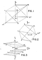
- the range, or gamut, of colors that can be faithfully reproduced using a conventional color display device can be represented in a three-dimensional rectangular Cartesian coordinate system, having R, G and B axes, by a cube, as shown in FIG. 1.
- the eight corners of the cube represent the three additive primary colors, the three additive secondary colors (magenta, yellow and cyan), black and white.
- the solid and dot-dashed lines between the corners of the cube represent the transitions between colors of a standard color bar signal.
- the point defined by the three color components of the target color must lie within the cube defined by the solid and dotted lines.
- the conventional vectorscope provides a two-dimensional display of the color difference components R-Y and B-Y.
- the vectorscope display is luminance independent, and may be thought of as representing a projection of the FIG. 1 cube into a plane that is perpendicular to the (1,1,1) vector. Therefore, the primary and secondary colors are represented by the corners of a regular hexagon and the center of the hexagon represents both black and white.
- the solid lines and the dot-dashed lines between corners of the hexagon represent transitions between colors of a standard color bar signal.
- Any validly reproducible color i.e. any color that can be represented by a point inside the color cube of FIG. 1, can also be represented by a point inside the hexagon defined by the solid and dotted lines of FIG. 2, but the converse is not true: not every point inside the hexagon of FIG. 2 corresponds to a point inside the cube of FIG. 1.
- R-Y and -Y vs. B-Y on alternate lines.
- the points representing the colors corresponding to the corners of the FIG. 1 cube are distributed in a zig-zag pattern (FIG. 3) down the display.
- a given color, defined by a set of values for R, G and B, is represented in this composite display by two points, one in the Y, R-Y space and the other in the Y, B-Y space.
- the solid and dot-dashed lines in FIG. 3 between the primary and secondary color points represent transitions between the colors of a standard color bar signal.
- the composite display described by Baker is particularly useful in observing timing and amplitude errors among the three components. It has been suggested that if a set of luminance and color difference values defines two points of which one lies inside the boundary defined by the solid and dotted lines in Y, R-Y space and the other of which lies inside the boundary defined by the solid and dotted lines in Y, B-Y space, then that set of values defines a validly reproducible color.
- the apparatus for providing a signal that indicates whether the color represented by a luminance and color difference component video signal is validly reproducible using a color display device.
- the apparatus comprises a matrix connected to receive the luminance and color difference components and generate primary color components therefrom, and a comparator for comparing the amplitude of each primary color component with predetermined minimum and maximum levels and providing an indication if the amplitude of one or more of the primary color components is outside the range established by the predetermined maximum and minimum values therefor.
- the apparatus shown in FIG. 4 comprises a conventional resistive matrix 10 that is connected to receive luminance and color difference components Y, R-Y and B-Y.
- the matrix provides the corresponding R, G, B components at its output, and each of these components is applied to two comparators 12 and 14.
- the comparator 12 receives at its reference signal a voltage representing the value 0 and the comparator provides a logical 1 output if the signal from the matrix has a value less than the voltage of the reference signal.
- the comparator 14 receives as its reference signal a voltage representing the value 1 and the comparator 14 provides a logical 1 at its output if the voltage of the signal provided by the matrix exceeds the voltage of the reference signal.
- the outputs of the comparators are applied to an OR gate 16, and the OR gate provides a gamut error signal at its output.
- the gamut error signal is applied to a display modifier 18 that is connected in the path of the Y, R-Y and B-Y components to a waveform or display monitor 20.
- the display modifier responds to a logical 1 provided by the OR gate 16 by modifying the luminance and color difference component signal to provide a visually distinct effect. For example, in the case of a display monitor, the display modifier may cause the display to blink, and in the case of a waveform monitor the display modifier may cause the display to be increased in brightness. Because the gamut error signal provided by the OR gate 16 is synchronous with the component video signal, the display modifier may only affect the area of the display for which the values R, G and B define a point that lies outside the color cube.
- the display modifier need not act on the video signal that is applied to the monitor 20.
- a color shutter may be incorporated in the monitor 20 and the gamut error signal applied directly to the monitor, as indicated by the dashed line in FIG. 4.
- the color shutter responds to the gamut error signal by modifying in a predetermined manner the image generated by the monitor.
- Color shutters that are at present commercially available are not capable of switching at frequencies much higher than the field frequency of a video signal (50 Hz or 60 Hz), and therefore if a color shutter is used as the display modifier the entire area of that display would be affected, e.g. by giving the display a characteristic color.
Abstract
Description
- This invention relates to an apparatus for providing an indication of color television signal validity.
- The term "color display device" is used herein to designate a device that comprises three primary color light sources which form separation images in the three additive primary colors (red, green and blue) respectively. In the case of a shadow-mask color CRT, the three light sources comprise the respective electron guns and the associated phosphor deposits. A color display device receives a video signal having three primary color components (R, G, and B), and is adjusted such that a minimum valid value of any one of the three components (R, G and B) drives the corresponding light source to a minimum, or perceived off, condition and a maximum valid value drives the light source to maximum brightness. Typically, the minimum valid value is zero volts and the maximum valid value is 0.7 volts; and these values may be represented as 0 and 1 respectively in arbitrary units. The primary color components R, G and B are generally derived from encoded luminance and color difference components (e.g. R-Y and B-Y) using a resistive matrix. The Y, R-Y and B-Y components in turn are derived from a composite video signal, such as a signal in accordance with the NTSC or PAL format, using well-known filtering and demodulating techniques. For many years, the only significant source of a video signal was a video camera, which generates the video signal in primary color component form, encodes the primary color components into luminance and color difference components, and then combines the latter components to produce the composite video signal. Also, for many years most processing of the video signal took place in the primary color component domain or in the composite (NTSC or PAL) domain and video signals were not processed in luminance and color difference component form.
- Since the values of the R, G and B components are independent variables, the range, or gamut, of colors that can be faithfully reproduced using a conventional color display device can be represented in a three-dimensional rectangular Cartesian coordinate system, having R, G and B axes, by a cube, as shown in FIG. 1. The eight corners of the cube represent the three additive primary colors, the three additive secondary colors (magenta, yellow and cyan), black and white. The solid and dot-dashed lines between the corners of the cube represent the transitions between colors of a standard color bar signal. In order for a color to be reproducible using a color display device, the point defined by the three color components of the target color must lie within the cube defined by the solid and dotted lines.
- The conventional vectorscope provides a two-dimensional display of the color difference components R-Y and B-Y. The vectorscope display is luminance independent, and may be thought of as representing a projection of the FIG. 1 cube into a plane that is perpendicular to the (1,1,1) vector. Therefore, the primary and secondary colors are represented by the corners of a regular hexagon and the center of the hexagon represents both black and white. In FIG. 2, the solid lines and the dot-dashed lines between corners of the hexagon represent transitions between colors of a standard color bar signal. Any validly reproducible color, i.e. any color that can be represented by a point inside the color cube of FIG. 1, can also be represented by a point inside the hexagon defined by the solid and dotted lines of FIG. 2, but the converse is not true: not every point inside the hexagon of FIG. 2 corresponds to a point inside the cube of FIG. 1.
- It has recently become common to generate composite video signals otherwise than from the primary color components. Such sources, e.g. television graphics systems, may generate signals directly in the luminance and color difference domain. Moreover, it has become common to process signals in the luminance and color difference domain. In Baker, "New and Unique Method for Measuring Video Analogue Component Signal Parameters" presented at the 19th Annual Winter SMPTE Conference held at San Francisco in February, 1985 and published in SMPTE Journal, October 1985, 1009, there is a discussion of a display format that is similar in some ways to a conventional vectorscope display but is particularly suited to a signal in luminance and color difference component format. The display described by Baker is a composite display of Y vs. R-Y and -Y vs. B-Y on alternate lines. The points representing the colors corresponding to the corners of the FIG. 1 cube are distributed in a zig-zag pattern (FIG. 3) down the display. A given color, defined by a set of values for R, G and B, is represented in this composite display by two points, one in the Y, R-Y space and the other in the Y, B-Y space. As in FIGS. 1 and 2, the solid and dot-dashed lines in FIG. 3 between the primary and secondary color points represent transitions between the colors of a standard color bar signal.
- The composite display described by Baker is particularly useful in observing timing and amplitude errors among the three components. It has been suggested that if a set of luminance and color difference values defines two points of which one lies inside the boundary defined by the solid and dotted lines in Y, R-Y space and the other of which lies inside the boundary defined by the solid and dotted lines in Y, B-Y space, then that set of values defines a validly reproducible color.
- The above-mentioned suggestion has been found to be incorrect. It can be shown that there are some combinations of Y, R-Y and B-Y that define a point that lies inside the boundary defined by the primary and secondary color points in the Y, R-Y space of the display shown in FIG. 3 and a point that lies inside the boundary defined by the primary and secondary color points in the Y, B-Y space but nevertheless defines a point that is outside the R, G, B color cube and therefore does not represent a validly reproducible color. For example, if Y = 0.886, B-Y = +0.114 and R-Y = -0.267, then R = 0.619, G = 1 and B = 1. Therefore R-Y = -0.267 is a valid value for Y = 0.886 within the Y, R-Y space. Similarly, for Y=0.886, B-Y = -0.886 and R-Y = +0.114, R = 1, G = 1 and B = 0, and therefore the value of -0.886 is a valid value for B-Y in the Y, B-Y space. However, if Y = 0.886, B-Y = -0.886 and R-Y = -0.267, then R = 0.619, B=0 and G = 1.194. Consequently, the fact that the value of B-Y is a valid value within the Y, B-Y space and that R-Y is a valid value within the Y, R-Y space is not sufficient to ensure that the color defined by Y, R-Y and B-Y is validly reproducible using a conventional color display device.
- In accordance with the present invention there is provided apparatus for providing a signal that indicates whether the color represented by a luminance and color difference component video signal is validly reproducible using a color display device. In a preferred embodiment, the apparatus comprises a matrix connected to receive the luminance and color difference components and generate primary color components therefrom, and a comparator for comparing the amplitude of each primary color component with predetermined minimum and maximum levels and providing an indication if the amplitude of one or more of the primary color components is outside the range established by the predetermined maximum and minimum values therefor.
- For a better understanding of the invention, and to show how the same may be carried into effect, reference will now be made, by way of example, to the accompanying drawings in which:
- FIG. 1 illustrates the color gamut by reference to a three-dimensional Cartesian coordinate system,
- FIG. 2 illustrates a conventional vectorscope .display of color bars,
- FIG. 3 illustrates a display of color bars using luminance and color difference as the coordi nates, and
- FIG. 4 is a block diagram of a device for indicating whether a video signal in luminance and color difference component form represents a validreproducible color.
- The apparatus shown in FIG. 4 comprises a conventional
resistive matrix 10 that is connected to receive luminance and color difference components Y, R-Y and B-Y. The matrix provides the corresponding R, G, B components at its output, and each of these components is applied to two comparators 12 and 14. The comparator 12 receives at its reference signal a voltage representing the value 0 and the comparator provides a logical 1 output if the signal from the matrix has a value less than the voltage of the reference signal. The comparator 14 receives as its reference signal a voltage representing the value 1 and the comparator 14 provides a logical 1 at its output if the voltage of the signal provided by the matrix exceeds the voltage of the reference signal. The outputs of the comparators are applied to anOR gate 16, and the OR gate provides a gamut error signal at its output. The gamut error signal is applied to adisplay modifier 18 that is connected in the path of the Y, R-Y and B-Y components to a waveform ordisplay monitor 20. The display modifier responds to a logical 1 provided by the ORgate 16 by modifying the luminance and color difference component signal to provide a visually distinct effect. For example, in the case of a display monitor, the display modifier may cause the display to blink, and in the case of a waveform monitor the display modifier may cause the display to be increased in brightness. Because the gamut error signal provided by theOR gate 16 is synchronous with the component video signal, the display modifier may only affect the area of the display for which the values R, G and B define a point that lies outside the color cube. - The display modifier need not act on the video signal that is applied to the
monitor 20. For example, a color shutter may be incorporated in themonitor 20 and the gamut error signal applied directly to the monitor, as indicated by the dashed line in FIG. 4. The color shutter responds to the gamut error signal by modifying in a predetermined manner the image generated by the monitor. Color shutters that are at present commercially available are not capable of switching at frequencies much higher than the field frequency of a video signal (50 Hz or 60 Hz), and therefore if a color shutter is used as the display modifier the entire area of that display would be affected, e.g. by giving the display a characteristic color. - It will be appreciated that the present invention is not restricted to the particular apparatus that has been described and illustrated with reference to FIG. 4, and that variations may be made therein without departing from the scope of the invention. For example, the invention is not restricted to the color difference components being R-Y and B-Y, and any other pair of components that are orthogonally related in the vectorscope display, such as the I and Q components, may be used instead.
Claims (6)
Applications Claiming Priority (2)
| Application Number | Priority Date | Filing Date | Title |
|---|---|---|---|
| US849615 | 1986-04-08 | ||
| US06/849,615 US4707727A (en) | 1986-04-08 | 1986-04-08 | Apparatus for providing an indication that a color represented by a Y, R-Y, B-Y color television signal is validly reproducible on an RGB color display device |
Publications (3)
| Publication Number | Publication Date |
|---|---|
| EP0240971A2 true EP0240971A2 (en) | 1987-10-14 |
| EP0240971A3 EP0240971A3 (en) | 1989-01-18 |
| EP0240971B1 EP0240971B1 (en) | 1992-03-04 |
Family
ID=25306124
Family Applications (1)
| Application Number | Title | Priority Date | Filing Date |
|---|---|---|---|
| EP87105063A Expired EP0240971B1 (en) | 1986-04-08 | 1987-04-06 | Apparatus for providing an indication of color television signal validity |
Country Status (6)
| Country | Link |
|---|---|
| US (1) | US4707727A (en) |
| EP (1) | EP0240971B1 (en) |
| JP (1) | JPS62239785A (en) |
| CA (1) | CA1257375A (en) |
| DE (1) | DE3776938D1 (en) |
| DK (1) | DK166248C (en) |
Cited By (5)
| Publication number | Priority date | Publication date | Assignee | Title |
|---|---|---|---|---|
| WO1993020660A1 (en) * | 1992-03-31 | 1993-10-14 | Minnesota Mining And Manufacturing Company | Color calibration for lcd panel |
| EP0606989A1 (en) * | 1993-01-13 | 1994-07-20 | Tektronix, Inc. | Three-dimensional RGB component vector display |
| EP0653880A1 (en) * | 1993-11-15 | 1995-05-17 | Nec Corporation | Apparatus for converting colour signals |
| EP2227032A1 (en) * | 2007-12-11 | 2010-09-08 | Leader Electronics Corp. | Brightness information display and method |
| CN109309575A (en) * | 2017-07-26 | 2019-02-05 | 贵州白山云科技股份有限公司 | A kind of method and apparatus of determining monitoring system health degree |
Families Citing this family (25)
| Publication number | Priority date | Publication date | Assignee | Title |
|---|---|---|---|---|
| US4758885A (en) * | 1985-06-17 | 1988-07-19 | Canon Kabushiki Kaisha | Method of processing color image |
| US4797738A (en) * | 1986-05-19 | 1989-01-10 | Kabushiki Kaisha Tohken | Color recognition apparatus |
| NO164630C (en) * | 1987-03-02 | 1990-10-24 | Norske Stats Oljeselskap | VIDEO SYSTEM FOR DETECTION OF COLORED SURFACES AND USE THEREOF IN A PROCEDURE FOR INTERPRETING SEIMIC SECTIONS. |
| US4908701A (en) * | 1987-03-09 | 1990-03-13 | Canon Kabushiki Kaisha | Color image processing method and apparatus for color adjustment during image processing |
| US4884130A (en) * | 1988-04-29 | 1989-11-28 | Minnesota Mining And Manufacturing Company | Method of describing a color in a triaxial planar vector color space |
| WO1990000849A1 (en) * | 1988-07-08 | 1990-01-25 | Commonwealth Scientific And Industrial Research Organisation | A real-time signal processing circuit |
| US4994901A (en) * | 1988-12-23 | 1991-02-19 | Eastman Kodak Company | Method and apparatus for increasing the gamut of an additive display driven from a digital source |
| US5122863A (en) * | 1990-09-14 | 1992-06-16 | Videotek, Inc. | Method and apparatus for simultaneous display of video signal attributes |
| JPH04291591A (en) * | 1991-03-19 | 1992-10-15 | Sony Corp | Color display device |
| US5319473A (en) * | 1991-11-27 | 1994-06-07 | Xerox Corporation | Methods and apparatus for performing real time color gamut compressions |
| IT1259343B (en) * | 1992-03-17 | 1996-03-12 | Sip | VIDEO CONTROL CIRCUIT FOR MULTIMEDIA APPLICATIONS |
| US5373327A (en) * | 1993-02-25 | 1994-12-13 | Hewlett-Packard Company | Detection, correction and display of illegal color information in a digital video signal |
| US5311295A (en) * | 1993-04-12 | 1994-05-10 | Tektronix, Inc. | RGB display of a transcoded serial digital signal |
| US5341226A (en) * | 1993-04-22 | 1994-08-23 | Xerox Corporation | Automatic image segmentation for color documents |
| US5519440A (en) * | 1994-01-18 | 1996-05-21 | Tektronix, Inc. | Composite signal-limit indicator for a component monitor |
| JP3126614B2 (en) * | 1994-01-31 | 2001-01-22 | キヤノン株式会社 | Image processing apparatus and method |
| EP0763928B1 (en) * | 1995-09-15 | 2001-10-10 | Agfa-Gevaert N.V. | Colour separation method and apparatus for same |
| US6219094B1 (en) * | 1999-04-16 | 2001-04-17 | Tektronix, Inc. | Non-linear filter for extracting luminance component from a composite video signal |
| JP2004147005A (en) * | 2002-10-23 | 2004-05-20 | Leader Electronics Corp | Apparatus for measuring video signal level, and apparatus for displaying the video signal level |
| JP4194859B2 (en) * | 2003-02-24 | 2008-12-10 | リーダー電子株式会社 | Video signal monitoring device |
| US7327384B2 (en) * | 2003-06-19 | 2008-02-05 | Tektronix, Inc. | Gamut false color display |
| US7403206B1 (en) * | 2003-10-01 | 2008-07-22 | Microsoft Corporation | Picking TV safe colors |
| JP4330438B2 (en) * | 2003-12-24 | 2009-09-16 | リーダー電子株式会社 | Video signal level display device |
| US7477286B2 (en) * | 2005-02-02 | 2009-01-13 | Tektronix, Inc. | Rectangular gamut display |
| WO2009025102A1 (en) * | 2007-08-20 | 2009-02-26 | Sony Corporation | Gamut error notification device |
Citations (2)
| Publication number | Priority date | Publication date | Assignee | Title |
|---|---|---|---|---|
| JPS5780891A (en) * | 1980-11-07 | 1982-05-20 | Pioneer Electronic Corp | Color emphasizing circuit |
| GB2144297A (en) * | 1983-07-11 | 1985-02-27 | Toshiba Kk | Automatic white control circuit for colour tv receiver |
Family Cites Families (6)
| Publication number | Priority date | Publication date | Assignee | Title |
|---|---|---|---|---|
| US4058828A (en) * | 1975-05-27 | 1977-11-15 | Eastman Kodak Company | Document copying apparatus |
| DE2607623B2 (en) * | 1976-02-25 | 1978-12-21 | Dr.-Ing. Rudolf Hell Gmbh, 2300 Kiel | Color evaluation device |
| JPS5948425B2 (en) * | 1977-02-28 | 1984-11-26 | 日本電気株式会社 | Color image analysis device |
| DE2719387C3 (en) * | 1977-04-30 | 1980-12-04 | Dr.-Ing. Rudolf Hell Gmbh, 2300 Kiel | Device for displaying overcorrections in electronic color correction |
| DE3264083D1 (en) * | 1981-11-25 | 1985-07-11 | Crosfield Electronics Ltd | Image reproduction |
| US4500919A (en) * | 1982-05-04 | 1985-02-19 | Massachusetts Institute Of Technology | Color reproduction system |
-
1986
- 1986-04-08 US US06/849,615 patent/US4707727A/en not_active Expired - Lifetime
-
1987
- 1987-03-12 CA CA000531880A patent/CA1257375A/en not_active Expired
- 1987-03-31 DK DK162687A patent/DK166248C/en not_active Application Discontinuation
- 1987-04-06 DE DE8787105063T patent/DE3776938D1/en not_active Expired - Lifetime
- 1987-04-06 EP EP87105063A patent/EP0240971B1/en not_active Expired
- 1987-04-07 JP JP62085599A patent/JPS62239785A/en active Granted
Patent Citations (2)
| Publication number | Priority date | Publication date | Assignee | Title |
|---|---|---|---|---|
| JPS5780891A (en) * | 1980-11-07 | 1982-05-20 | Pioneer Electronic Corp | Color emphasizing circuit |
| GB2144297A (en) * | 1983-07-11 | 1985-02-27 | Toshiba Kk | Automatic white control circuit for colour tv receiver |
Non-Patent Citations (2)
| Title |
|---|
| PATENT ABSTRACTS OF JAPAN, vol. 6, no. 160 (E-126)[1038], 21st August 1982; & JP-A-57 080 891 (PIONEER K.K.) 20-05-1982 * |
| S.M.P.T.E. JOURNAL, vol. 94, no. 10, October 1985, pages 1009-1014, Scarsdale, New York, US; D. BAKER: "A new and unique method for measuring video analog component signal parameters" * |
Cited By (10)
| Publication number | Priority date | Publication date | Assignee | Title |
|---|---|---|---|---|
| WO1993020660A1 (en) * | 1992-03-31 | 1993-10-14 | Minnesota Mining And Manufacturing Company | Color calibration for lcd panel |
| US5369432A (en) * | 1992-03-31 | 1994-11-29 | Minnesota Mining And Manufacturing Company | Color calibration for LCD panel |
| EP0606989A1 (en) * | 1993-01-13 | 1994-07-20 | Tektronix, Inc. | Three-dimensional RGB component vector display |
| EP0653880A1 (en) * | 1993-11-15 | 1995-05-17 | Nec Corporation | Apparatus for converting colour signals |
| US6097398A (en) * | 1993-11-15 | 2000-08-01 | Nec Corporation | Apparatus for converting color signals |
| US6388676B1 (en) | 1993-11-15 | 2002-05-14 | Nec Corporation | Apparatus for converting color signals |
| EP2227032A1 (en) * | 2007-12-11 | 2010-09-08 | Leader Electronics Corp. | Brightness information display and method |
| EP2227032A4 (en) * | 2007-12-11 | 2012-01-18 | Leader Electronics | Brightness information display and method |
| US8279348B2 (en) | 2007-12-11 | 2012-10-02 | Leader Electronics Corporation | Luminance information display apparatus and method |
| CN109309575A (en) * | 2017-07-26 | 2019-02-05 | 贵州白山云科技股份有限公司 | A kind of method and apparatus of determining monitoring system health degree |
Also Published As
| Publication number | Publication date |
|---|---|
| JPH0477518B2 (en) | 1992-12-08 |
| CA1257375A (en) | 1989-07-11 |
| EP0240971A3 (en) | 1989-01-18 |
| DE3776938D1 (en) | 1992-04-09 |
| DK162687D0 (en) | 1987-03-31 |
| JPS62239785A (en) | 1987-10-20 |
| DK166248C (en) | 1993-11-08 |
| DK162687A (en) | 1987-10-09 |
| EP0240971B1 (en) | 1992-03-04 |
| DK166248B (en) | 1993-03-22 |
| US4707727A (en) | 1987-11-17 |
Similar Documents
| Publication | Publication Date | Title |
|---|---|---|
| EP0240971B1 (en) | Apparatus for providing an indication of color television signal validity | |
| CN1040827C (en) | Video system character display device | |
| US5940140A (en) | Backing luminance non-uniformity compensation in real-time compositing systems | |
| US4914506A (en) | Component color bar alignment test signal | |
| US5519440A (en) | Composite signal-limit indicator for a component monitor | |
| US6327003B1 (en) | Method for correcting flicker and flutter effects of an on-screen display on a video image | |
| US4092666A (en) | Monochrome presentation of demodulated color signals | |
| EP0329382B1 (en) | Luminance signal/color signal separation circuit | |
| EP0313372A1 (en) | YC separator for video signal processing circuit | |
| US5282020A (en) | Device for generating horizontal scanning periodic signal of pal-system to obtain clear display image | |
| CA1170797A (en) | Display video apparatus | |
| EP0309726B1 (en) | Method for inserting test lines | |
| EP1383345B1 (en) | Vectorscope | |
| KR910013891A (en) | Auxiliary video information encoding and decoding device for television system | |
| JPH0810986Y2 (en) | Television receiver | |
| US4191965A (en) | Apparatus and method for testing color sequencing of secam color television signals | |
| JP3365001B2 (en) | Motion adaptive luminance signal color signal separation filter | |
| JPH01108890A (en) | Yc separation circuit | |
| JP3017873B2 (en) | Black and white video signal output device | |
| JPH0380395B2 (en) | ||
| JPS62114393A (en) | Color television signal processor | |
| JPH0720274B2 (en) | Motion vector display method | |
| JPS61267794A (en) | Display controller | |
| JPH0580876B2 (en) | ||
| JPH08251617A (en) | Rgb monitor |
Legal Events
| Date | Code | Title | Description |
|---|---|---|---|
| PUAI | Public reference made under article 153(3) epc to a published international application that has entered the european phase |
Free format text: ORIGINAL CODE: 0009012 |
|
| AK | Designated contracting states |
Kind code of ref document: A2 Designated state(s): DE FR GB NL |
|
| PUAL | Search report despatched |
Free format text: ORIGINAL CODE: 0009013 |
|
| AK | Designated contracting states |
Kind code of ref document: A3 Designated state(s): DE FR GB NL |
|
| 17P | Request for examination filed |
Effective date: 19890613 |
|
| 17Q | First examination report despatched |
Effective date: 19910702 |
|
| GRAA | (expected) grant |
Free format text: ORIGINAL CODE: 0009210 |
|
| AK | Designated contracting states |
Kind code of ref document: B1 Designated state(s): DE FR GB NL |
|
| REF | Corresponds to: |
Ref document number: 3776938 Country of ref document: DE Date of ref document: 19920409 |
|
| PGFP | Annual fee paid to national office [announced via postgrant information from national office to epo] |
Ref country code: NL Payment date: 19920430 Year of fee payment: 6 |
|
| ET | Fr: translation filed | ||
| PGFP | Annual fee paid to national office [announced via postgrant information from national office to epo] |
Ref country code: FR Payment date: 19920728 Year of fee payment: 6 |
|
| PLBE | No opposition filed within time limit |
Free format text: ORIGINAL CODE: 0009261 |
|
| STAA | Information on the status of an ep patent application or granted ep patent |
Free format text: STATUS: NO OPPOSITION FILED WITHIN TIME LIMIT |
|
| 26N | No opposition filed | ||
| PG25 | Lapsed in a contracting state [announced via postgrant information from national office to epo] |
Ref country code: NL Effective date: 19931101 |
|
| NLV4 | Nl: lapsed or anulled due to non-payment of the annual fee | ||
| PG25 | Lapsed in a contracting state [announced via postgrant information from national office to epo] |
Ref country code: FR Effective date: 19931229 |
|
| REG | Reference to a national code |
Ref country code: FR Ref legal event code: ST |
|
| REG | Reference to a national code |
Ref country code: GB Ref legal event code: IF02 |
|
| PGFP | Annual fee paid to national office [announced via postgrant information from national office to epo] |
Ref country code: GB Payment date: 20060316 Year of fee payment: 20 |
|
| PGFP | Annual fee paid to national office [announced via postgrant information from national office to epo] |
Ref country code: DE Payment date: 20060317 Year of fee payment: 20 |
|
| REG | Reference to a national code |
Ref country code: GB Ref legal event code: PE20 |
|
| PG25 | Lapsed in a contracting state [announced via postgrant information from national office to epo] |
Ref country code: GB Free format text: LAPSE BECAUSE OF EXPIRATION OF PROTECTION Effective date: 20070405 |