EP0242460A1 - Monomer atomizer for vaporization - Google Patents
Monomer atomizer for vaporization Download PDFInfo
- Publication number
- EP0242460A1 EP0242460A1 EP86302995A EP86302995A EP0242460A1 EP 0242460 A1 EP0242460 A1 EP 0242460A1 EP 86302995 A EP86302995 A EP 86302995A EP 86302995 A EP86302995 A EP 86302995A EP 0242460 A1 EP0242460 A1 EP 0242460A1
- Authority
- EP
- European Patent Office
- Prior art keywords
- tip portion
- chamber
- combination
- vaporization
- tip
- Prior art date
- Legal status (The legal status is an assumption and is not a legal conclusion. Google has not performed a legal analysis and makes no representation as to the accuracy of the status listed.)
- Withdrawn
Links
Images
Classifications
-
- B—PERFORMING OPERATIONS; TRANSPORTING
- B01—PHYSICAL OR CHEMICAL PROCESSES OR APPARATUS IN GENERAL
- B01D—SEPARATION
- B01D1/00—Evaporating
- B01D1/16—Evaporating by spraying
-
- B—PERFORMING OPERATIONS; TRANSPORTING
- B01—PHYSICAL OR CHEMICAL PROCESSES OR APPARATUS IN GENERAL
- B01D—SEPARATION
- B01D3/00—Distillation or related exchange processes in which liquids are contacted with gaseous media, e.g. stripping
- B01D3/006—Distillation or related exchange processes in which liquids are contacted with gaseous media, e.g. stripping by vibration
-
- B—PERFORMING OPERATIONS; TRANSPORTING
- B01—PHYSICAL OR CHEMICAL PROCESSES OR APPARATUS IN GENERAL
- B01D—SEPARATION
- B01D3/00—Distillation or related exchange processes in which liquids are contacted with gaseous media, e.g. stripping
- B01D3/06—Flash distillation
-
- B—PERFORMING OPERATIONS; TRANSPORTING
- B05—SPRAYING OR ATOMISING IN GENERAL; APPLYING FLUENT MATERIALS TO SURFACES, IN GENERAL
- B05B—SPRAYING APPARATUS; ATOMISING APPARATUS; NOZZLES
- B05B17/00—Apparatus for spraying or atomising liquids or other fluent materials, not covered by the preceding groups
- B05B17/04—Apparatus for spraying or atomising liquids or other fluent materials, not covered by the preceding groups operating with special methods
- B05B17/06—Apparatus for spraying or atomising liquids or other fluent materials, not covered by the preceding groups operating with special methods using ultrasonic or other kinds of vibrations
- B05B17/0607—Apparatus for spraying or atomising liquids or other fluent materials, not covered by the preceding groups operating with special methods using ultrasonic or other kinds of vibrations generated by electrical means, e.g. piezoelectric transducers
- B05B17/0623—Apparatus for spraying or atomising liquids or other fluent materials, not covered by the preceding groups operating with special methods using ultrasonic or other kinds of vibrations generated by electrical means, e.g. piezoelectric transducers coupled with a vibrating horn
- B05B17/063—Apparatus for spraying or atomising liquids or other fluent materials, not covered by the preceding groups operating with special methods using ultrasonic or other kinds of vibrations generated by electrical means, e.g. piezoelectric transducers coupled with a vibrating horn having an internal channel for supplying the liquid or other fluent material
-
- B—PERFORMING OPERATIONS; TRANSPORTING
- B05—SPRAYING OR ATOMISING IN GENERAL; APPLYING FLUENT MATERIALS TO SURFACES, IN GENERAL
- B05B—SPRAYING APPARATUS; ATOMISING APPARATUS; NOZZLES
- B05B7/00—Spraying apparatus for discharge of liquids or other fluent materials from two or more sources, e.g. of liquid and air, of powder and gas
- B05B7/16—Spraying apparatus for discharge of liquids or other fluent materials from two or more sources, e.g. of liquid and air, of powder and gas incorporating means for heating or cooling the material to be sprayed
- B05B7/1686—Spraying apparatus for discharge of liquids or other fluent materials from two or more sources, e.g. of liquid and air, of powder and gas incorporating means for heating or cooling the material to be sprayed involving vaporisation of the material to be sprayed or of an atomising-fluid-generating product
-
- C—CHEMISTRY; METALLURGY
- C23—COATING METALLIC MATERIAL; COATING MATERIAL WITH METALLIC MATERIAL; CHEMICAL SURFACE TREATMENT; DIFFUSION TREATMENT OF METALLIC MATERIAL; COATING BY VACUUM EVAPORATION, BY SPUTTERING, BY ION IMPLANTATION OR BY CHEMICAL VAPOUR DEPOSITION, IN GENERAL; INHIBITING CORROSION OF METALLIC MATERIAL OR INCRUSTATION IN GENERAL
- C23C—COATING METALLIC MATERIAL; COATING MATERIAL WITH METALLIC MATERIAL; SURFACE TREATMENT OF METALLIC MATERIAL BY DIFFUSION INTO THE SURFACE, BY CHEMICAL CONVERSION OR SUBSTITUTION; COATING BY VACUUM EVAPORATION, BY SPUTTERING, BY ION IMPLANTATION OR BY CHEMICAL VAPOUR DEPOSITION, IN GENERAL
- C23C14/00—Coating by vacuum evaporation, by sputtering or by ion implantation of the coating forming material
- C23C14/22—Coating by vacuum evaporation, by sputtering or by ion implantation of the coating forming material characterised by the process of coating
- C23C14/24—Vacuum evaporation
- C23C14/246—Replenishment of source material
-
- H—ELECTRICITY
- H01—ELECTRIC ELEMENTS
- H01G—CAPACITORS; CAPACITORS, RECTIFIERS, DETECTORS, SWITCHING DEVICES OR LIGHT-SENSITIVE DEVICES, OF THE ELECTROLYTIC TYPE
- H01G13/00—Apparatus specially adapted for manufacturing capacitors; Processes specially adapted for manufacturing capacitors not provided for in groups H01G4/00 - H01G11/00
-
- Y—GENERAL TAGGING OF NEW TECHNOLOGICAL DEVELOPMENTS; GENERAL TAGGING OF CROSS-SECTIONAL TECHNOLOGIES SPANNING OVER SEVERAL SECTIONS OF THE IPC; TECHNICAL SUBJECTS COVERED BY FORMER USPC CROSS-REFERENCE ART COLLECTIONS [XRACs] AND DIGESTS
- Y10—TECHNICAL SUBJECTS COVERED BY FORMER USPC
- Y10S—TECHNICAL SUBJECTS COVERED BY FORMER USPC CROSS-REFERENCE ART COLLECTIONS [XRACs] AND DIGESTS
- Y10S159/00—Concentrating evaporators
- Y10S159/16—Vacuum
-
- Y—GENERAL TAGGING OF NEW TECHNOLOGICAL DEVELOPMENTS; GENERAL TAGGING OF CROSS-SECTIONAL TECHNOLOGIES SPANNING OVER SEVERAL SECTIONS OF THE IPC; TECHNICAL SUBJECTS COVERED BY FORMER USPC CROSS-REFERENCE ART COLLECTIONS [XRACs] AND DIGESTS
- Y10—TECHNICAL SUBJECTS COVERED BY FORMER USPC
- Y10S—TECHNICAL SUBJECTS COVERED BY FORMER USPC CROSS-REFERENCE ART COLLECTIONS [XRACs] AND DIGESTS
- Y10S159/00—Concentrating evaporators
- Y10S159/23—Cooling
-
- Y—GENERAL TAGGING OF NEW TECHNOLOGICAL DEVELOPMENTS; GENERAL TAGGING OF CROSS-SECTIONAL TECHNOLOGIES SPANNING OVER SEVERAL SECTIONS OF THE IPC; TECHNICAL SUBJECTS COVERED BY FORMER USPC CROSS-REFERENCE ART COLLECTIONS [XRACs] AND DIGESTS
- Y10—TECHNICAL SUBJECTS COVERED BY FORMER USPC
- Y10S—TECHNICAL SUBJECTS COVERED BY FORMER USPC CROSS-REFERENCE ART COLLECTIONS [XRACs] AND DIGESTS
- Y10S159/00—Concentrating evaporators
- Y10S159/90—Concentrating evaporators using vibratory force
Definitions
- This invention relates generally to converting liquids into gaseous form and more particularly concerns atomizing monomeric liquids for flash evaporation.
- flash vaporization i.e., subjecting small particles of liquid to vaporization heat for almost instantaneous vaporization, allows the resin to remain in monomer form through the process of being deposited, and then the capacitor making process cures and cross links the material.
- flash vaporization depends on creating very small particles, i.e., atomizing, the liquid material. Monomers, being rather viscous, are difficult to atomize. Spraying under liquid pressure tends to produce a vaporization rate far in excess of what is desirable for the extremely thin layer deposition desired. Utilizing a compressed gas to create a spray is unsuitable in the vacuum environment utilized for the deposition.
- a further object is to provide an atomizer as characterized above that is economical to manufacture and maintain, since it is based on standard instruments and structures.
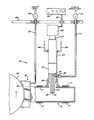
- the single figure is a schematic partially sectioned apparatus embodying an atomizer formed in accordance with the invention.
- the liquid is atomized by a structure 15 embodying the invention, vaporized in a vaporization chamber 16 heated by heaters 17, and deposited through nozzle structure 18 onto the drum surface 13.
- the nozzle structure 18 controls the vapor deposition in part by confining vapor flow with inert gas, supplied through a line 21 and valve 22.
- the apparatus 10 is mounted within a vacuum chamber 23.
- the structure 15 is essentially monolithic with a tip portion 31 at one end extending, and delivering liquid, into the vaporization chamber 16 and having an ultrasonic vibration device 32 coupled at the opposite end.
- the structure 15 is supported by a collar 34 that closes the chamber opening through which the tip portion 31 extends and which is fixed to the tip portion at approximately its nodal point.
- the tip portion 31 has a necked-down tip 35 ending in a surface 36 to which the liquid is directed through a capillary passage 37 in the tip portion 31 that is connected to the liquid feed line 11 by a compression coupling 38.
- the device 32 preferably a piezoelectric crystal transducer, is energized by an electronic power supply 39 through a line 41.
- Ultrasonic vibration of the tip 35 and its surface 36 causes the liquid to flow from the passage 37, coat the surface 36 and be dispersed in fine droplets through a widespread pattern in the chamber 16.
- the pattern seen is in the form of a shallow cone when a substantially flat surface like the surface 36 is utilized.
- the liquid Upon striking the hot chamber walls, temperatures of 350° to 400° F. being typical, the liquid is vaporized, creating gaseous pressure driving the vapor through the nozzle structure 18 so as to be deposited on the surface 13.
- the structure 15 includes a cooling coupling 43 interposed between and rigidly connected to the tip portion 31 and the vibration device 32. Cooling water is directed through a passage in the coupling 43 using lines 44. The coupling 43 and the cooling water absorb and remove heat conducted from the vaporization chamber 16 along the tip portion 31 so that extreme temperatures cannot adversely affect the vibrating device 32. To minimize vibration absorption, the lines 38, 44 and the connection with the collar 34 are located at or near the vibration node positions. The structure 15 is left supported cantilever fashion by the collar 34 so that the device 32 can vibrate undampened.
- the basic structure represented by the tip portion 31, vibration device 32 and electronics 39 can be found in standard laboratory equipment such as ultrasonic emulsifying devices and this utilization of relatively standard components makes the atomizer structure economical to manufacture and maintain.
Abstract
An atomizer with a capillary passage (37) to a tip surface (36) which is vibrated by a directly coupled ultrasonic device (32) to disperse droplets of liquid fed to the passage (37). The tip is associated with a heated evaporization chamber (16) and a cooling chamber between the tip (35) and the ultrasonic device (32) protects the device from the heat of the chamber.
Description
- This invention relates generally to converting liquids into gaseous form and more particularly concerns atomizing monomeric liquids for flash evaporation.
- United States application Serial No. 620,647, filed June 14, 1984, on Miniature Monolithic Multilayer Capacitor and Apparatus and Method of Making, discloses methods and apparatus for making miniature electrical capacitors. The process involves vapor deposition in a deep vacuum environment, and one material that is deposited is a resin in monomer form that, when deposited and cured, forms the dielectric layers of a monolithic capacitor structure.
- The techniques of flash vaporization, i.e., subjecting small particles of liquid to vaporization heat for almost instantaneous vaporization, allows the resin to remain in monomer form through the process of being deposited, and then the capacitor making process cures and cross links the material. As just suggested, flash vaporization depends on creating very small particles, i.e., atomizing, the liquid material. Monomers, being rather viscous, are difficult to atomize. Spraying under liquid pressure tends to produce a vaporization rate far in excess of what is desirable for the extremely thin layer deposition desired. Utilizing a compressed gas to create a spray is unsuitable in the vacuum environment utilized for the deposition.
- It is an object of the invention to provide an atomizer, particularly suited for flash vaporization and vacuum depositing a monomeric liquid, that creates small widely dispersed droplets of viscous liquid. Another object is to provide an atomizer of the foregoing kind that can be associated directly with a heated vaporization chamber.
- A further object is to provide an atomizer as characterized above that is economical to manufacture and maintain, since it is based on standard instruments and structures.
- Other objects and advantages of the invention will become apparent upon reading the following detailed description and upon reference to the drawing, in which:
The single figure is a schematic partially sectioned apparatus embodying an atomizer formed in accordance with the invention. - While the invention will be described in connection with a preferred embodiment, it will be understood that we do not intend to limit the invention to that embodiment. On the contrary, I intend to cover all alternatives, modifications and equivalents as may be included within the spirit and scope of the invention as defined by the appended claims.
- Turning to the drawing, there is shown an
apparatus 10 for vaporizing a monomeric liquid supplied through a line 11 andvalve 12, and vacuum depositing the vapor onto asurface 13 carried by a rotatingdrum 14. The liquid is atomized by astructure 15 embodying the invention, vaporized in avaporization chamber 16 heated byheaters 17, and deposited throughnozzle structure 18 onto thedrum surface 13. Thenozzle structure 18 controls the vapor deposition in part by confining vapor flow with inert gas, supplied through aline 21 andvalve 22. Theapparatus 10 is mounted within avacuum chamber 23. - The general arrangement and overall purpose of the
apparatus 10 can be seen by referring to said application Serial No. 620,647, which is hereby specifically incorporated by reference. - In accordance with the invention, the
structure 15 is essentially monolithic with atip portion 31 at one end extending, and delivering liquid, into thevaporization chamber 16 and having anultrasonic vibration device 32 coupled at the opposite end. Thestructure 15 is supported by acollar 34 that closes the chamber opening through which thetip portion 31 extends and which is fixed to the tip portion at approximately its nodal point. Thetip portion 31 has a necked-down tip 35 ending in asurface 36 to which the liquid is directed through acapillary passage 37 in thetip portion 31 that is connected to the liquid feed line 11 by acompression coupling 38. Thedevice 32, preferably a piezoelectric crystal transducer, is energized by an electronic power supply 39 through a line 41. Ultrasonic vibration of thetip 35 and itssurface 36 causes the liquid to flow from thepassage 37, coat thesurface 36 and be dispersed in fine droplets through a widespread pattern in thechamber 16. The pattern seen is in the form of a shallow cone when a substantially flat surface like thesurface 36 is utilized. Upon striking the hot chamber walls, temperatures of 350° to 400° F. being typical, the liquid is vaporized, creating gaseous pressure driving the vapor through thenozzle structure 18 so as to be deposited on thesurface 13. - The lengths of the
coupling 43 andtip portion 31 correspond to one-half wavelength of the vibration, and thedevice 32 is operated at their fundamental frequency mode with maximum amplitude of motion at thesurface 36 and minimum movement, or node positions, at the attachment points of thecoupling 43 andtip portion 31. To protect thevibration device 32 from heat, thestructure 15 includes acooling coupling 43 interposed between and rigidly connected to thetip portion 31 and thevibration device 32. Cooling water is directed through a passage in thecoupling 43 usinglines 44. Thecoupling 43 and the cooling water absorb and remove heat conducted from thevaporization chamber 16 along thetip portion 31 so that extreme temperatures cannot adversely affect thevibrating device 32. To minimize vibration absorption, thelines collar 34 are located at or near the vibration node positions. Thestructure 15 is left supported cantilever fashion by thecollar 34 so that thedevice 32 can vibrate undampened. - It has been found that a material like titanium alloy 6AL4V is suitable for the
tip portion 31. The diameter of thepassage 37 is dependent upon the flow rate of the liquid being conveyed through the line 11, and diameters of 20 mils to 1/8ʺ have been found suitable. - The basic structure represented by the
tip portion 31,vibration device 32 and electronics 39 can be found in standard laboratory equipment such as ultrasonic emulsifying devices and this utilization of relatively standard components makes the atomizer structure economical to manufacture and maintain.
Claims (9)
1. An atomizer for liquids to be vaporized comprising, in combination, an elongated unitary structure having a tip portion at one end, an ultrasonic vibration device coupled to the opposite end of said structure, means for energizing said device to impart ultrasonic vibration to said tip portion, the tip portion having an end surface and defining a capillary passage ending at said end surface, the tip being mounted such that the end surface is located at approximately one-quarter wavelength from a nodal position, and means for conveying liquid to said passage for liquid flow onto said surface and dispersion into atomized liquid particles.
2. The combination of claim 1 including a cooling chamber interposed between said tip portion and said device, and means for flowing cooling fluid through said chamber.
3. The combination of claim 1 in which said tip portion has a necked-down tip ending in said surface, said tip portion being solid hard metal except for said passage.
4. A liquid vaporization apparatus comprising, in combination, a vacuum chamber, a heated vaporization chamber mounted in said vacuum chamber, an elongated unitary structure mounted in said vacuum chamber including a tip portion at one end extending into said vaporization chamber, an ultrasonic vibration device coupled to the opposite end of said structure, means for energizing said device to impart ultrasonic vibration to said tip portion, said tip portion having an end surface located approximately one-quarter wavelength from a nodal position and defining a capillary passage ending at said end surface, means for conveying liquid to said passage for liquid flow onto said surface and dispersion into atomized liquid particles to be vaporized, a cooling chamber interposed in said structure between said vaporization chamber and said device, and means for flowing cooling fluid through said chamber so as to thermally isolate the device from the vaporization chamber.
5. An apparatus according to claim 4 wherein the unitary structure also includes a coupling portion connected to the tip portion.
6. An apparatus according to claim 5 wherein the coupling portion includes the cooling chamber.
7. The combination of claims 1 or 4 wherein the length of said tip portion corresponds to one-quarter wavelength of the vibration imparted by said device.
8. The combination of claims 1 or 4 wherein the length of said structure corresponds to one wavelength of the vibration imparted by said device.
9. The combination of claims 1 or 4 wherein said device imparts vibration at the fundamental frequency mode of said structure with maximum amplitude of motion at said surface.
Priority Applications (2)
| Application Number | Priority Date | Filing Date | Title |
|---|---|---|---|
| EP86302995A EP0242460A1 (en) | 1985-01-18 | 1986-04-21 | Monomer atomizer for vaporization |
| US06/900,241 US4696719A (en) | 1985-01-18 | 1986-08-25 | Monomer atomizer for vaporization |
Applications Claiming Priority (3)
| Application Number | Priority Date | Filing Date | Title |
|---|---|---|---|
| US69274685A | 1985-01-18 | 1985-01-18 | |
| EP86302995A EP0242460A1 (en) | 1985-01-18 | 1986-04-21 | Monomer atomizer for vaporization |
| US06/900,241 US4696719A (en) | 1985-01-18 | 1986-08-25 | Monomer atomizer for vaporization |
Publications (1)
| Publication Number | Publication Date |
|---|---|
| EP0242460A1 true EP0242460A1 (en) | 1987-10-28 |
Family
ID=39627623
Family Applications (1)
| Application Number | Title | Priority Date | Filing Date |
|---|---|---|---|
| EP86302995A Withdrawn EP0242460A1 (en) | 1985-01-18 | 1986-04-21 | Monomer atomizer for vaporization |
Country Status (2)
| Country | Link |
|---|---|
| US (1) | US4696719A (en) |
| EP (1) | EP0242460A1 (en) |
Cited By (2)
| Publication number | Priority date | Publication date | Assignee | Title |
|---|---|---|---|---|
| EP1577020A3 (en) * | 2004-03-20 | 2008-03-19 | Henkel Kommanditgesellschaft auf Aktien | Device for applying adhesives |
| US7491433B2 (en) | 2002-06-26 | 2009-02-17 | E.I. Du Pont De Nemours And Company | Coated sheet materials and packages made therewith |
Families Citing this family (102)
| Publication number | Priority date | Publication date | Assignee | Title |
|---|---|---|---|---|
| US5391262A (en) * | 1990-04-23 | 1995-02-21 | Wilkerson, Jr.; William | Solar still vibrator |
| US5440446A (en) * | 1993-10-04 | 1995-08-08 | Catalina Coatings, Inc. | Acrylate coating material |
| KR100241470B1 (en) | 1993-10-04 | 2000-02-01 | 지. 쇼 데이비드 | Cross-linked acrylate coating material useful for forming capacitor dielectric |
| US20040241454A1 (en) * | 1993-10-04 | 2004-12-02 | Shaw David G. | Barrier sheet and method of making same |
| US5545375A (en) * | 1994-10-03 | 1996-08-13 | Becton, Dickinson And Company | Blood collection tube assembly |
| US5877895A (en) * | 1995-03-20 | 1999-03-02 | Catalina Coatings, Inc. | Multicolor interference coating |
| US6218004B1 (en) | 1995-04-06 | 2001-04-17 | David G. Shaw | Acrylate polymer coated sheet materials and method of production thereof |
| US5811183A (en) * | 1995-04-06 | 1998-09-22 | Shaw; David G. | Acrylate polymer release coated sheet materials and method of production thereof |
| US5681615A (en) * | 1995-07-27 | 1997-10-28 | Battelle Memorial Institute | Vacuum flash evaporated polymer composites |
| US5683771A (en) * | 1996-01-30 | 1997-11-04 | Becton, Dickinson And Company | Blood collection tube assembly |
| US5702770A (en) * | 1996-01-30 | 1997-12-30 | Becton, Dickinson And Company | Method for plasma processing |
| US5763033A (en) | 1996-01-30 | 1998-06-09 | Becton, Dickinson And Company | Blood collection tube assembly |
| US5686157A (en) * | 1996-01-30 | 1997-11-11 | Becton, Dickinson And Company | Blood collection tube assembly |
| US5955161A (en) | 1996-01-30 | 1999-09-21 | Becton Dickinson And Company | Blood collection tube assembly |
| US5716683A (en) * | 1996-01-30 | 1998-02-10 | Becton, Dickinson And Company | Blood collection tube assembly |
| US5738920A (en) * | 1996-01-30 | 1998-04-14 | Becton, Dickinson And Company | Blood collection tube assembly |
| US6203898B1 (en) | 1997-08-29 | 2001-03-20 | 3M Innovatave Properties Company | Article comprising a substrate having a silicone coating |
| US6045864A (en) | 1997-12-01 | 2000-04-04 | 3M Innovative Properties Company | Vapor coating method |
| US6012647A (en) * | 1997-12-01 | 2000-01-11 | 3M Innovative Properties Company | Apparatus and method of atomizing and vaporizing |
| US5904958A (en) * | 1998-03-20 | 1999-05-18 | Rexam Industries Corp. | Adjustable nozzle for evaporation or organic monomers |
| US6251334B1 (en) | 1998-03-23 | 2001-06-26 | Presstek, Inc. | Composite constructions having mixed organic/inorganic layers |
| AU729498B2 (en) | 1998-03-23 | 2001-02-01 | Presstek, Inc. | Lithographic imaging with constructions having mixed organic/inorganic layers |
| US20030178734A1 (en) * | 1998-10-23 | 2003-09-25 | Karl Josephy | Process for making angstrom scale and high aspect functional platelets |
| US6863851B2 (en) * | 1998-10-23 | 2005-03-08 | Avery Dennison Corporation | Process for making angstrom scale and high aspect functional platelets |
| US6398999B1 (en) | 1998-10-23 | 2002-06-04 | Avery Dennison Corporation | Process for making high aspect ratio reflective metal flakes |
| WO2000026973A1 (en) | 1998-11-02 | 2000-05-11 | Presstek, Inc. | Transparent conductive oxides for plastic flat panel displays |
| US6503564B1 (en) | 1999-02-26 | 2003-01-07 | 3M Innovative Properties Company | Method of coating microstructured substrates with polymeric layer(s), allowing preservation of surface feature profile |
| US6172810B1 (en) | 1999-02-26 | 2001-01-09 | 3M Innovative Properties Company | Retroreflective articles having polymer multilayer reflective coatings |
| DE10049856A1 (en) * | 2000-10-09 | 2002-03-07 | Siemens Ag | Device for continuously vaporizing small amounts of liquid in heated vaporizing chamber comprises capillary which introduces liquid slowly into vaporizing chamber, and device for exciting free end of capillary |
| US6802315B2 (en) | 2001-03-21 | 2004-10-12 | Hollingsorth & Vose Company | Vapor deposition treated electret filter media |
| AU2002305393A1 (en) * | 2001-05-04 | 2002-11-18 | General Atomics | O2 and h2o barrier material |
| US6933051B2 (en) | 2002-08-17 | 2005-08-23 | 3M Innovative Properties Company | Flexible electrically conductive film |
| US7215473B2 (en) | 2002-08-17 | 2007-05-08 | 3M Innovative Properties Company | Enhanced heat mirror films |
| US6929864B2 (en) * | 2002-08-17 | 2005-08-16 | 3M Innovative Properties Company | Extensible, visible light-transmissive and infrared-reflective film and methods of making and using the film |
| US6818291B2 (en) * | 2002-08-17 | 2004-11-16 | 3M Innovative Properties Company | Durable transparent EMI shielding film |
| US7018713B2 (en) * | 2003-04-02 | 2006-03-28 | 3M Innovative Properties Company | Flexible high-temperature ultrabarrier |
| CN102794256B (en) * | 2003-05-27 | 2014-12-10 | 松下电器产业株式会社 | Method and apparatus for creating environment where mist of charged water particle is dispersed |
| JP4232542B2 (en) * | 2003-06-04 | 2009-03-04 | パナソニック電工株式会社 | Electrostatic atomizer and humidifier equipped with the same |
| CA2595065A1 (en) * | 2004-11-30 | 2006-06-08 | The Administrators Of The Tulane Educational Fund | Nebulizing treatment method |
| US20070020451A1 (en) | 2005-07-20 | 2007-01-25 | 3M Innovative Properties Company | Moisture barrier coatings |
| KR20080080154A (en) * | 2005-12-29 | 2008-09-02 | 쓰리엠 이노베이티브 프로퍼티즈 컴파니 | Method for atomizing material for coating processes |
| US20080006819A1 (en) * | 2006-06-19 | 2008-01-10 | 3M Innovative Properties Company | Moisture barrier coatings for organic light emitting diode devices |
| BRPI0721299B1 (en) | 2006-12-28 | 2018-07-24 | 3M Innovative Properties Company. | METHOD FOR FORMATION OF A CONDUCTIVE FILM ON A FLEXIBLE POLYMER HOLDER, CONDUCTORY FILM AND METHOD FOR THE MANUFACTURE OF A VITRIFICATION ARTICLE |
| US20100068542A1 (en) * | 2006-12-29 | 2010-03-18 | 3M Innovative Properties Company | Method of making inorganic or inorganic/organic hybrid films |
| EP2118336B1 (en) * | 2006-12-29 | 2017-02-15 | 3M Innovative Properties Company | Method of curing metal alkoxide-containing films |
| EP2212726A1 (en) * | 2007-10-30 | 2010-08-04 | 3M Innovative Properties Company | Multi-stack optical bandpass film with electro magnetic interference shielding for optical display filters |
| JP2011508062A (en) * | 2007-12-28 | 2011-03-10 | スリーエム イノベイティブ プロパティズ カンパニー | Flexible encapsulated film system |
| KR101550946B1 (en) * | 2007-12-28 | 2015-09-07 | 쓰리엠 이노베이티브 프로퍼티즈 컴파니 | Infrared reflecting films for solar control and other uses |
| US8350451B2 (en) | 2008-06-05 | 2013-01-08 | 3M Innovative Properties Company | Ultrathin transparent EMI shielding film comprising a polymer basecoat and crosslinked polymer transparent dielectric layer |
| US8348177B2 (en) * | 2008-06-17 | 2013-01-08 | Davicon Corporation | Liquid dispensing apparatus using a passive liquid metering method |
| EP2304069A4 (en) * | 2008-06-30 | 2012-01-04 | 3M Innovative Properties Co | Method of making inorganic or inorganic/organic hybrid barrier films |
| US8038952B2 (en) * | 2008-08-28 | 2011-10-18 | General Electric Company | Surface treatments and coatings for flash atomization |
| US20110223434A1 (en) * | 2008-11-17 | 2011-09-15 | Roehrig Mark A | Gradient composition barrier |
| WO2010120468A1 (en) | 2009-04-15 | 2010-10-21 | 3M Innovative Properties Company | Process and apparatus for a nanovoided article |
| US9291752B2 (en) | 2013-08-19 | 2016-03-22 | 3M Innovative Properties Company | Retroreflecting optical construction |
| US9464179B2 (en) | 2009-04-15 | 2016-10-11 | 3M Innovative Properties Company | Process and apparatus for a nanovoided article |
| IN2011CN07418A (en) | 2009-04-15 | 2015-08-21 | 3M Innovative Properties Co | |
| TWI491930B (en) | 2009-04-15 | 2015-07-11 | 3M新設資產公司 | Optical film |
| SG178225A1 (en) | 2009-08-03 | 2012-03-29 | 3M Innovative Properties Co | Process for forming optically clear conductive metal or metal alloy thin films and films made therefrom |
| WO2011062836A1 (en) | 2009-11-18 | 2011-05-26 | 3M Innovative Properties Company | Multi-layer optical films |
| US9791604B2 (en) | 2010-04-15 | 2017-10-17 | 3M Innovative Properties Company | Retroreflective articles including optically active areas and optically inactive areas |
| KR101960149B1 (en) | 2010-04-15 | 2019-03-19 | 쓰리엠 이노베이티브 프로퍼티즈 캄파니 | Retroreflective articles including optically active areas and optically inactive areas |
| KR101954456B1 (en) | 2010-04-15 | 2019-03-05 | 쓰리엠 이노베이티브 프로퍼티즈 캄파니 | Retroreflective articles including optically active areas and optically inactive areas |
| WO2012003417A1 (en) | 2010-07-02 | 2012-01-05 | 3M Innovative Properties Company | Barrier assembly with encapsulant and photovoltaic cell |
| US9254506B2 (en) | 2010-07-02 | 2016-02-09 | 3M Innovative Properties Company | Moisture resistant coating for barrier films |
| WO2012047422A1 (en) | 2010-10-06 | 2012-04-12 | 3M Innovative Properties Company | Anti-reflective articles with nanosilica-based coatings |
| CN103154319B (en) | 2010-10-06 | 2016-08-10 | 3M创新有限公司 | There is coating based on nano silicon and the antireflective article on barrier layer |
| SG2014007876A (en) | 2011-08-04 | 2014-03-28 | 3M Innovative Properties Co | Edge protected barrier assemblies |
| KR102040758B1 (en) | 2011-08-05 | 2019-11-05 | 쓰리엠 이노베이티브 프로퍼티즈 캄파니 | Systems and methods for processing vapor |
| US20150114457A1 (en) * | 2012-03-01 | 2015-04-30 | 3M Innovative Properties Company | Continuous edge protected barrier assemblies |
| BR112015002836A2 (en) | 2012-08-08 | 2018-04-24 | 3M Innovative Properties Co | photovoltaic devices with encapsulation barrier film. |
| EP2882761B1 (en) | 2012-08-08 | 2017-04-19 | 3M Innovative Properties Company | Urea (multi)-urethane (meth)acrylate-silane compositions and articles including the same |
| TWI610806B (en) | 2012-08-08 | 2018-01-11 | 3M新設資產公司 | Barrier film, method of making the barrier film, and articles including the barrier film |
| WO2014025570A1 (en) | 2012-08-08 | 2014-02-13 | 3M Innovative Properties Company | Barrier film constructions and methods of making same |
| US10784455B2 (en) | 2012-08-08 | 2020-09-22 | 3M Innovative Properties Company | Coatings for barrier films and methods of making and using the same |
| CN104937685A (en) | 2012-11-21 | 2015-09-23 | 3M创新有限公司 | Multilayer film including first and second dielectric layers |
| US20150294793A1 (en) | 2012-11-21 | 2015-10-15 | 3M Innovative Properties Company | Multilayer film including first and second dielectric layers |
| WO2014100580A1 (en) | 2012-12-20 | 2014-06-26 | 3M Innovative Properties Company | Fluoropolymer composition including an oligomer having an ultraviolet absorbing group |
| TW201433580A (en) | 2012-12-20 | 2014-09-01 | 3M Innovative Properties Co | Copolymers including ultraviolet absorbing groups and fluoropolymer compositions including them |
| EP3024883A1 (en) | 2013-07-24 | 2016-06-01 | 3M Innovative Properties Company | Adhesive barrier film construction |
| US9782955B2 (en) | 2013-09-24 | 2017-10-10 | 3M Innovative Properties Company | Transferable transparent conductive patterns and display stack materials |
| US11110689B2 (en) | 2014-06-25 | 2021-09-07 | 3M Innovative Properties Company | Pressure sensitive adhesive composition including ultraviolet light-absorbing oligomer |
| WO2015200655A1 (en) | 2014-06-25 | 2015-12-30 | 3M Innovative Properties Company | Fluoropolymer composition including at least one oligomer |
| WO2015200657A1 (en) | 2014-06-25 | 2015-12-30 | 3M Innovative Properties Company | Copolymers including a triazine group and compositions including them |
| US10519350B2 (en) | 2015-06-25 | 2019-12-31 | 3M Innovative Properties Company | Copolymer including ultraviolet light-absorbing group and compositions including the same |
| CN107922805B (en) | 2015-08-17 | 2020-09-15 | 3M创新有限公司 | Nanoclay-filled barrier adhesive composition |
| CN107925010B (en) | 2015-08-17 | 2020-11-06 | 3M创新有限公司 | Barrier film construction |
| US11584113B2 (en) | 2015-08-19 | 2023-02-21 | 3M Innovative Properties Company | Composite article including a multilayer barrier assembly and methods of making the same |
| WO2017031294A1 (en) | 2015-08-19 | 2017-02-23 | 3M Innovative Properties Company | Composite article including a multilayer barrier assembly and methods of making the same |
| EP3337847B1 (en) | 2015-08-19 | 2019-07-10 | 3M Innovative Properties Company | Composite article and methods of making the same |
| KR20180079382A (en) | 2015-10-30 | 2018-07-10 | 존슨 앤드 존슨 컨수머 인코포레이티드 | Aseptic aerosol misting device |
| EP3368113B1 (en) | 2015-10-30 | 2022-06-01 | Johnson & Johnson Consumer Inc. | Unit dose aseptic aerosol misting device |
| RU2721489C2 (en) | 2015-10-30 | 2020-05-19 | Джонсон энд Джонсон Консьюмер Инк. | Aseptic aerosol fog generator |
| EP3368110B1 (en) | 2015-10-30 | 2020-12-02 | Johnson & Johnson Consumer Inc. | Aseptic aerosol misting device |
| CN109075262A (en) | 2016-03-25 | 2018-12-21 | 3M创新有限公司 | Multilayer barrier film |
| US10894903B2 (en) | 2016-06-16 | 2021-01-19 | 3M Innovative Properties Company | Nanoparticle filled barrier adhesive compositions |
| WO2017218500A1 (en) | 2016-06-16 | 2017-12-21 | 3M Innovative Properties Company | Nanoparticle filled barrier adhesive compositions |
| WO2018080830A1 (en) | 2016-10-28 | 2018-05-03 | 3M Innovative Properties Company | Nanostructured article |
| WO2018193392A1 (en) | 2017-04-21 | 2018-10-25 | 3M Innovative Properties Company | Barrier adhesive compositions and articles |
| WO2019111182A1 (en) | 2017-12-06 | 2019-06-13 | 3M Innovative Properties Company | Barrier adhesive compositions and articles |
| US20240023350A1 (en) | 2020-12-09 | 2024-01-18 | 3M Innovative Properties Company | Barrier assembly for solar cells |
| CN117320889A (en) | 2021-05-20 | 2023-12-29 | 3M创新有限公司 | Micro-cut patterned article and method of making the same |
Citations (4)
| Publication number | Priority date | Publication date | Assignee | Title |
|---|---|---|---|---|
| US3328610A (en) * | 1964-07-13 | 1967-06-27 | Branson Instr | Sonic wave generator |
| GB1104172A (en) * | 1965-03-30 | 1968-02-21 | Metal Containers Ltd | Glow discharge polymerization process |
| US3400892A (en) * | 1965-12-02 | 1968-09-10 | Battelle Development Corp | Resonant vibratory apparatus |
| EP0147696A2 (en) * | 1983-12-19 | 1985-07-10 | SPECTRUM CONTROL, INC. (a Pennsylvania corporation) | Miniaturized monolithic multi-layer capacitor and apparatus and method for making |
Family Cites Families (16)
| Publication number | Priority date | Publication date | Assignee | Title |
|---|---|---|---|---|
| US2192140A (en) * | 1935-09-20 | 1940-02-27 | Chicago Television & Res Lab I | Device for transferring liquids in vacuum |
| US2265762A (en) * | 1940-04-09 | 1941-12-09 | Shell Dev | Separation of phases with the aid of sonic waves |
| US2437963A (en) * | 1943-03-24 | 1948-03-16 | Gen Electric | Method and apparatus for producing aerosols |
| US2695871A (en) * | 1951-09-25 | 1954-11-30 | Abbott Lab | Rotary molecular vacuum still |
| US2949900A (en) * | 1958-06-02 | 1960-08-23 | Albert G Bodine | Sonic liquid sprayer |
| DE1495654A1 (en) * | 1960-09-27 | 1969-04-10 | Foster Grant & Co Inc | Process and device for the continuous recovery of a gas mixture consisting of lactams and amide oligomers from polyamides contaminated with this mixture |
| US3103310A (en) * | 1961-11-09 | 1963-09-10 | Exxon Research Engineering Co | Sonic atomizer for liquids |
| US3371059A (en) * | 1963-02-21 | 1968-02-27 | Teknika Inc | Monomer stripping |
| US3273631A (en) * | 1964-01-13 | 1966-09-20 | Neuman Entpr Ltd | Ultrasonic fluid heating, vaporizing, cleaning and separating apparatus |
| US3306829A (en) * | 1966-04-27 | 1967-02-28 | Arthur H Thomas Company | Magnetic stirrer in a still |
| US4085893A (en) * | 1974-03-20 | 1978-04-25 | Durley Iii Benton A | Ultrasonic humidifiers, atomizers and the like |
| US4267976A (en) * | 1978-03-10 | 1981-05-19 | Chatwin Francis R | Apparatus for vaporizing and atomizing liquids |
| GB2024048B (en) * | 1978-06-29 | 1982-08-11 | Plessey Co Ltd | Vibratory atomiser |
| SE425055B (en) * | 1978-12-18 | 1982-08-30 | Erik Allan Lindkvist | DEVICE FOR THERMAL SPRAYING DEVICE |
| DE3010985A1 (en) * | 1980-03-21 | 1981-10-01 | Siemens AG, 1000 Berlin und 8000 München | FUEL INJECTION NOZZLE WITH ADDITIONAL FUEL SPRAYING |
| DE3124854C2 (en) * | 1981-06-24 | 1985-03-14 | Reinhard 8057 Eching Mühlbauer | High pressure injection system with ultrasonic atomization |
-
1986
- 1986-04-21 EP EP86302995A patent/EP0242460A1/en not_active Withdrawn
- 1986-08-25 US US06/900,241 patent/US4696719A/en not_active Expired - Lifetime
Patent Citations (4)
| Publication number | Priority date | Publication date | Assignee | Title |
|---|---|---|---|---|
| US3328610A (en) * | 1964-07-13 | 1967-06-27 | Branson Instr | Sonic wave generator |
| GB1104172A (en) * | 1965-03-30 | 1968-02-21 | Metal Containers Ltd | Glow discharge polymerization process |
| US3400892A (en) * | 1965-12-02 | 1968-09-10 | Battelle Development Corp | Resonant vibratory apparatus |
| EP0147696A2 (en) * | 1983-12-19 | 1985-07-10 | SPECTRUM CONTROL, INC. (a Pennsylvania corporation) | Miniaturized monolithic multi-layer capacitor and apparatus and method for making |
Cited By (2)
| Publication number | Priority date | Publication date | Assignee | Title |
|---|---|---|---|---|
| US7491433B2 (en) | 2002-06-26 | 2009-02-17 | E.I. Du Pont De Nemours And Company | Coated sheet materials and packages made therewith |
| EP1577020A3 (en) * | 2004-03-20 | 2008-03-19 | Henkel Kommanditgesellschaft auf Aktien | Device for applying adhesives |
Also Published As
| Publication number | Publication date |
|---|---|
| US4696719A (en) | 1987-09-29 |
Similar Documents
| Publication | Publication Date | Title |
|---|---|---|
| US4696719A (en) | Monomer atomizer for vaporization | |
| US3243122A (en) | Ultrasonic spray apparatus | |
| US6053424A (en) | Apparatus and method for ultrasonically producing a spray of liquid | |
| US6789741B2 (en) | Method and apparatus for atomizing liquids having minimal droplet size | |
| US5145113A (en) | Ultrasonic generation of a submicron aerosol mist | |
| JPS61259784A (en) | Vibrator for ultrasonic injection | |
| GB2154472A (en) | Apparatus for atomising liquids | |
| US5173274A (en) | Flash liquid aerosol production method and appartus | |
| US4701348A (en) | Method of coating the threads of a fastener | |
| US4123481A (en) | Device for carburetion of liquid fuels | |
| JPS61259780A (en) | Vibrator for ultrasonic atomization | |
| JP3375652B2 (en) | Method and apparatus for producing spherical monodisperse particles | |
| JPS62289259A (en) | Atomizer for evaporating monomer | |
| JPS58180259A (en) | Atomizing device | |
| JPH0411965A (en) | Controlling method for ultrasonic wave atomizer | |
| SU1007752A1 (en) | Ultrasonic liquid sprayer | |
| Luhovskyi et al. | Journal of the Technical University of Gabrovo | |
| KR900003969B1 (en) | Vibrating element for ultrasonic atomization having curved multi-stepped edged portion | |
| JP2735325B2 (en) | Ultrasonic atomizer | |
| JPS6384664A (en) | Cooled ultrasonic atomizer | |
| Asai et al. | A new hollow cylindrical ultrasonic wave radiator | |
| WO2008076622A1 (en) | Method of producing a directed spray | |
| JPH04334566A (en) | Atomizing device | |
| JPH11138072A (en) | Atomizer | |
| JPH0332764A (en) | Ultrasonic atomizing device |
Legal Events
| Date | Code | Title | Description |
|---|---|---|---|
| PUAI | Public reference made under article 153(3) epc to a published international application that has entered the european phase |
Free format text: ORIGINAL CODE: 0009012 |
|
| AK | Designated contracting states |
Kind code of ref document: A1 Designated state(s): DE FR GB IT NL SE |
|
| STAA | Information on the status of an ep patent application or granted ep patent |
Free format text: STATUS: THE APPLICATION IS DEEMED TO BE WITHDRAWN |
|
| 18D | Application deemed to be withdrawn |
Effective date: 19880429 |
|
| RIN1 | Information on inventor provided before grant (corrected) |
Inventor name: BISCHOFF, GREGG CORDELL |