EP0245024A2 - Radio communication system with power saving disablement prior to call handling processes - Google Patents
Radio communication system with power saving disablement prior to call handling processes Download PDFInfo
- Publication number
- EP0245024A2 EP0245024A2 EP87303847A EP87303847A EP0245024A2 EP 0245024 A2 EP0245024 A2 EP 0245024A2 EP 87303847 A EP87303847 A EP 87303847A EP 87303847 A EP87303847 A EP 87303847A EP 0245024 A2 EP0245024 A2 EP 0245024A2
- Authority
- EP
- European Patent Office
- Prior art keywords
- power saving
- signal
- station
- disabling
- power
- Prior art date
- Legal status (The legal status is an assumption and is not a legal conclusion. Google has not performed a legal analysis and makes no representation as to the accuracy of the status listed.)
- Granted
Links
Images


Classifications
-
- H—ELECTRICITY
- H04—ELECTRIC COMMUNICATION TECHNIQUE
- H04B—TRANSMISSION
- H04B7/00—Radio transmission systems, i.e. using radiation field
- H04B7/14—Relay systems
-
- H—ELECTRICITY
- H04—ELECTRIC COMMUNICATION TECHNIQUE
- H04B—TRANSMISSION
- H04B7/00—Radio transmission systems, i.e. using radiation field
- H04B7/14—Relay systems
- H04B7/15—Active relay systems
- H04B7/155—Ground-based stations
-
- H—ELECTRICITY
- H04—ELECTRIC COMMUNICATION TECHNIQUE
- H04B—TRANSMISSION
- H04B7/00—Radio transmission systems, i.e. using radiation field
-
- H—ELECTRICITY
- H04—ELECTRIC COMMUNICATION TECHNIQUE
- H04B—TRANSMISSION
- H04B7/00—Radio transmission systems, i.e. using radiation field
- H04B7/24—Radio transmission systems, i.e. using radiation field for communication between two or more posts
- H04B7/26—Radio transmission systems, i.e. using radiation field for communication between two or more posts at least one of which is mobile
-
- H—ELECTRICITY
- H04—ELECTRIC COMMUNICATION TECHNIQUE
- H04W—WIRELESS COMMUNICATION NETWORKS
- H04W52/00—Power management, e.g. TPC [Transmission Power Control], power saving or power classes
- H04W52/02—Power saving arrangements
- H04W52/0209—Power saving arrangements in terminal devices
- H04W52/0225—Power saving arrangements in terminal devices using monitoring of external events, e.g. the presence of a signal
- H04W52/0229—Power saving arrangements in terminal devices using monitoring of external events, e.g. the presence of a signal where the received signal is a wanted signal
-
- H—ELECTRICITY
- H04—ELECTRIC COMMUNICATION TECHNIQUE
- H04W—WIRELESS COMMUNICATION NETWORKS
- H04W52/00—Power management, e.g. TPC [Transmission Power Control], power saving or power classes
- H04W52/02—Power saving arrangements
- H04W52/0209—Power saving arrangements in terminal devices
- H04W52/0225—Power saving arrangements in terminal devices using monitoring of external events, e.g. the presence of a signal
- H04W52/0238—Power saving arrangements in terminal devices using monitoring of external events, e.g. the presence of a signal where the received signal is an unwanted signal, e.g. interference or idle signal
-
- H—ELECTRICITY
- H04—ELECTRIC COMMUNICATION TECHNIQUE
- H04W—WIRELESS COMMUNICATION NETWORKS
- H04W76/00—Connection management
- H04W76/10—Connection setup
-
- H—ELECTRICITY
- H04—ELECTRIC COMMUNICATION TECHNIQUE
- H04W—WIRELESS COMMUNICATION NETWORKS
- H04W88/00—Devices specially adapted for wireless communication networks, e.g. terminals, base stations or access point devices
- H04W88/02—Terminal devices
- H04W88/04—Terminal devices adapted for relaying to or from another terminal or user
-
- Y—GENERAL TAGGING OF NEW TECHNOLOGICAL DEVELOPMENTS; GENERAL TAGGING OF CROSS-SECTIONAL TECHNOLOGIES SPANNING OVER SEVERAL SECTIONS OF THE IPC; TECHNICAL SUBJECTS COVERED BY FORMER USPC CROSS-REFERENCE ART COLLECTIONS [XRACs] AND DIGESTS
- Y02—TECHNOLOGIES OR APPLICATIONS FOR MITIGATION OR ADAPTATION AGAINST CLIMATE CHANGE
- Y02D—CLIMATE CHANGE MITIGATION TECHNOLOGIES IN INFORMATION AND COMMUNICATION TECHNOLOGIES [ICT], I.E. INFORMATION AND COMMUNICATION TECHNOLOGIES AIMING AT THE REDUCTION OF THEIR OWN ENERGY USE
- Y02D30/00—Reducing energy consumption in communication networks
- Y02D30/70—Reducing energy consumption in communication networks in wireless communication networks
Definitions
- the present invention relates to power saving for radio communication systems.
- origination of a call requires transmission of a long packet of data from terminal stations during an active interval of the system to request the base station to issue a series of signals according to protocols.
- the transmission of a call origination request signal results in the disablement of power saving in the repeater and terminal stations to permit them to process the signals.
- call origination attempts from terminal stations tend to concentrate during the limited time interval and encouter data collision.
- the base station would generate a series of protocols, resulting in fruitless data exchanges along the network causing a systemwide traffic congestion.
- the above object is obtained by transmitting a disabling signal during the limited active period from a terminal station to a repeater station prior to the transmission of a call request signal.
- the disabling signal disables the power saving operations of the repeater station and the own terminal station and allows the latter to receive signals relayed through the active repeater station and send a call request signal to it so that a series of call processing signals can be handled during the power saving disabled period. Since the power saving disabling signal can be a short packet of data and induces no protocol actions in the base station, its probability of encountering collision is very slight and hence a systemwide traffic congestion cannot occur even if data collision occurs.
- the power saving disabling signal is transmitted after a randomly determined period of time following a transition from an inactive period to an active period.
- the terminal station is arranged to transmit a call request signal after a randomly determined period following the reception of a signal relayed by the repeater station which is rendered active in response to the disabling signal.
- a radio communication system of the invention comprises a base station for transmitting a power saving signal and an information signal, a repeater station for relaying the signals, and a plurality of terminal stations for communicating with the base station through the repeater station.
- the repeater station includes power saving circuitry responsive to the power saving signal to cut off power supplies to its major power consumptive components during a preset interval which alternates with an active interval during which power is supplied to the components.
- Each terminal station includes power saving circuitry responsive to the power saving signal relayed by the repeater station to cut off power supplies to its major power consumptive components during the preset interval and power saving disabling circuitry for transmitting a power saving disabling signal to the repeater station during the active interval in response to a request for call and disabling its power saving circuitry for the duration of the preset interval.
- the repeater station includes power saving disabling circuitry which is responsive to the power saving disabling signal from a terminal station to disable its power saving circuitry for the duration of the preset interval to thereby permit the information signal to he relayed to the terminal station which has transmitted the power saving disabling signal.
- Each terminal station transmits a call request signal to the repeater station to thereby permit it to be handled during the interval in which power saving is disabled.
- a time division multiple access (TDMA) radio concentrator system of the invention comprises a base station 10 connected to subscriber line terminals of an end office switching system 11 of the public telecommunication network, repeater stations 12 and 13 and terminal stations 14 and 15 which are located in remote, thinnly populated areas.
- Terminal stations 14 are located in an area that is appropriate for establishing communications with the repeater station 12 and terminal stations 15 are located in another area approprite for communication with the repeater station 13. All the terminal stations 14 and 15 have their corresponding subscriber line terminals at the end office switching system 11.
- the base station 10 provides line concentration by switching the subscriber lines to a smaller number of "downstream" TDMA channels and as viewed from the terminal stations it provides deconcentration by switching the "upstream" TDMA channels to the subscriber lines.
- Each terminal station has connected to it a subscriber station such as telephone and telefax machine. All the repeater and terminal stations operate on individual battery supplies.
- the base station comprises a line concentrator 20, a plurality of PCM codecs (coder/decoders) 21 provided in number corresponding to the number of two-way TDMA channels and a time slot controller 22.
- Time slot controller 22 is associated with each of the codecs 21, concentrator 20, radio transmitter 23 and radio receiver 24.
- Each codec 21 has a hybrid, a PCM coder for encoding an outgoing analog signal coupled through the hybrid from the concentrator 20 and applying the encoded outgoing signal on a specified outgoing time slot to transmitter 23 and a PCM decoder for decoding an incoming digital signal from receiver 24 on a specified incoming time slot and applying the decoded signal through the hybrid to the concentrator 20.
- Transmitter 23 modulates a carrier with the TDM bit stream using a digital modulation technique and amplifies the modulated carrier to a level sufficient for transmission, the output of transmitter 23 being coupled through duplexer 25 to antenna 26.
- Receiver 24 amplifies and demodulates a digitally modulated RF signal received by antenna 26 to recover baseband TDM signals.
- time-slot controller 22 generates a timing reference to permit each codec to determine a particular one of the time slots TSO to TSn of a "frame".
- Time slot TSO comprises a plurality of "fields".
- the first field contains a preamble from which the receiving stations recover clock signals.
- the preamble consists of a series of 16 bits of alternating binary l's and 0's.
- a frame sync code which is also a 16-bit series of a unique code format (typically, "1010010100110110", is inserted to the second field of the time slot TSO.
- a battery saving (BS) code is inserted to the third field of the first time slot and is followed by a control field in which signaling and time slot assignment information is inserted.
- the BS code determines the timing reference with which all the repeater and terminal stations are synchronized to cut off their battery supplies at periodic intervals to conserve their power.
- the BS code comprises "1010" (BS-ON) for power cut-off and "0101" (BS-OFF) for power restoration. To achieve most efficient power savings, frames containing the BS-ON code are repeated so as to continue for a period of time much longer than the period in which frames having the BS-OFF code continue.
- the frames containing the BS-ON code are termed "D-frames" and those containing the BS-OFF code are termed "C-frames".
- the time slot TSO is followed by a series of information carrying time slots TS1 to TSn each having a 16-bit time-slot sync having a bit pattern "1010010100110111" which differs from the frame sync in that the least significant bit is a binary 1.
- the time slots TS1 to TSn correspond respectively to the codecs 21.
- a consecutive series of power-cutoff D-frames alternates with a consecutive series of power-restoration C-frames and transmitted from the antenna 26 on a broadcast mode through repeater stations 12 and 13 to all terminal stations 14 and 15.
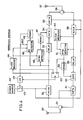
- Fig. 4 illustrates details of each repeater station.
- the broadcast time-division multiplexed signal is intercepted by an antenna 30 and applied through duplexer 31 to a radio receiver 32 and applied on a "downstream" signal transmission path including a delay 33 and a gate 34 to a radio transmitter 35 whose output is coupled through duplexer 36 to antenna 37.
- Burst signals transmitted on assigned time slots from the associated terminal station are received by antenna 37, passed through duplexer 36 to a radio receiver and applied on an "upstream" signal transmission path including a delay 39 and a gate 40 to a radio transmitter 41 and thence to duplexer 31.
- Receivers 32, 38 and transmitters 35 and 41 which are the main power consumptive components of the repeater station, are powered from a power source, or storage batteries 42 through normally open contacts of a power-saving switch 43 which is controlled in a manner as will be described.
- Receiver 32 amplifies the downstream radio-frequency TDM signal and demodulates it to recover the baseband TDM signal.
- the output of receiver 32 is applied to a clock recovery circuit 44, a sync detector 45 and a BS detector 46.
- Clock recovery circuit 44 detects a preamble from the received bit stream to recover clock timing and supplies clock pulses to sync detector 45 and BS detector 46.
- Sync detector 45 essentially comprises a shift register which is clocked by the clock recovery circuit 44 to accept the output of receiver 32 and a digital comparator which compares the binary states of the loaded data bit stream with the code format of the sync and generates an equality output when they match, this output being applied as a trigger signal to a monostable multivibrator 47 and as an enabling signal to the BS detector 46.
- the downstream TDM output of receiver 32 is timed by delay 33 so that it passes to the transmitter 35 through gate 34 in response to a gate-on pulse from the monostable 47.
- Transmitter 35 modulates the output of gate 34 upon a carrier frequency different from the carrier frequency transmitted from the base station and applies it through duplexer 36 to antenna 37.
- the BS detector 46 is constructed in a manner similar to sync detector to detect the BS-ON code immediately following the detection of a sync code by sync detector 45.
- a timer 48 is connected to the output of BS detector 46 to operate the_battery-saving switch 43 through an OR gate 49.
- Timer 48 may be formed of a monostable multivibrator and an inverter connected to the output of the monostable to generate a logical 0 output (power cutoff signal) of a duration slightly longer than the duration of a series of D-frames in response to the receipt of a single BS-ON code that occurs at the first of the series of D-frames.
- BS detector 46 is implemented by a shift register 54 which is clocked by the clock recovery circuit 44 to receive the output of receiver 32.
- a digital comparator 55 compares the common bit pattern (i.e., the 15-bit pattern of "101001010011011") of the frame and time-slot sync codes with the contents of the binary positions QO to Q14 of the shift register 54 to supply a coincidence output upon the arrival of each frame and time-slot sync code to an AND gate 57 to which the clock pulses are also applied through an inverter 58.
- a second digital comparator 56 makes comparison with the BS-ON code pattern "1010" with the contents of the binary positions Q16 to Q19 of the shift register to supply a coincidence output at the beginning of each frame to the D input of a D-flip-flop 59 having a clock input to which the output of AND gate 57 is applied.
- the output of timer 48 is connected to the reset input of D-flip-flop 59 to prevent it from responding to BS-ON codes that occur after the timer 48 has been activated in response to the detection of a BS-ON code of first occurrence during the power saving disablement.
- D-flip-flop 59 switches to a significant binary level at the trailing edge of a pulse from clock recovery circuit 44 when the flip-flop is supplied with logical 1 outputs from both comparators during the first time slot TSO and switches to an insignificant binary level at the trailing edge of a subsequent clock pulse when the flip-flop is supplied with logical 1 and 0 outputs from comparators 55 and 56, respectively, during the second time slot TS1.
- D-flip-flop 59 generates an output pulse with a duration of a single time slot at the starting point of each D-frame.
- the switch 43 remains open to cut off power supplies to the power consumptive units.
- the output of timer 48 automatically switches to a logical 1 level to cause the switch 43 to close its contacts to reactivate the power consumptive units.
- the receiver 38 In the "upstream" section of the repeater station, the receiver 38 amplifies the radio-frequency TDM signal from antenna 37 and demodulates it to recover the baseband TDM signal which is applied to a clock recovery circuit 50.
- Clock recovery circuit 50 detects a preamble from the bit stream received from the terminal stations and recovers clock timing.
- a sync detector 51 is synchronized to the clock pulse from the clock recovery circuit 50 and detects a sync code contained in the received TDM bit stream.
- the output of sync detector 51 drives a monostable multivibrator 52 to open the gate 40 to pass the TDM bit stream, which is appropriately timed by the delay 39, to transmitter 41 where it is modulated upon a particular carrier frequency and amplified for transmission to the base station.
- a battery saving inhibit flip-flop 53 is provided. This flip-flop responds to the output of sync detector 51 by supplying a logical 1 output through OR gate 49 to switch 43 to inhibit battery saving operation and further responds to the logical 1 output (power restoring signal) of timer 48 by supplying a logical 0 output to switch 43 to allow it to open its contacts to resume battery saving operation.
- each terminal station couples battery supplies to a receiver 60 and a transmitter 61 from a storage battery 62 through a power saving switch 63.
- the relayed radio-frequency TDM signal is intercepted by antenna 64 and applied through duplexer 65 to receiver 60 where it is amplified and demodulated.
- the output of receiver 60 is applied to the decoder input of a PCM codec 66, the encoder output of which is connected to transmitter 61.
- Codec 66 is connected over a subscriber line to a telephone set 67 to convert the analog speech signal into digital form and insert the digital signal to a time slot specified by a controller 68 for application to transmitter 61.
- Codec 66 detects a digital signal on a specified time slot of the recovered TDM baseband signal and converts it to an analog form for application to the telephone 67.
- a clock recovery circuit 69 derives clock timing from the preamble of the relayed bit stream and causes a sync detector 70 to detect a sync code immediately following the preamble.
- Sync detector 70 enables a BS detector 71 to detect a BS-ON code from the battery saving field of the bit stream.
- the BS detector 71 drives a timer 72 upon detection of a BS-ON code to cause a power cutoff signal of the same duration as in the repeater station to be generated. This power cutoff signal is applied through an OR gate 73 to power saving switch 63.
- Controller 68 is responsive to the outputs of clock recovery circuit 69 and sync detector 70 to detect the time slot on which the "downstream" signal is carried to cause the codec 66 to decode the digital signal on the detected time slot to analog form for application to telephone 67 and specify a time slot on which the "upstream" digital signal to be inserted.
- a code generator 74 is connected to the controller 68 to generate a bit sequence comprising a preamble and a sync code to be inserted to the beginning of a specified time slot to permit the receiving stations to establish clock and frame synchronization whenever speech or signaling information is transmitted.
- controller 68 monitors the output of timer 72 to detect a transition from an active interval (BS-OFF) to an inactive interval (BS-ON) and generates a battery saving inhibit command signal after a random time period following the detection of the transition which occurs after telephone 67 goes off hook for call origination.
- This BS inhibit command signal is applied to the code generator 74 to cause a BS inhibit code to be generated.
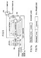
- This inhibit code comprises a preamble, a sync code and a dummy code as shown in Fig. 7a to be transmitted to the repeater station to inhibit its battery saving operation.
- This BS inhibit command signal is also applied to the set input of a battery saving inhibit flip-flop 75 to cause it to apply a logical 1 output through OR gate 73 to switch 63 to close its contacts.
- Flip-flop 75 is reset in response to a power cutoff signal from timer 72 to apply a logical 0 output to switch 63 to resume battery saving operation.
- controller 68 is conditioned to monitor the arrival of a sync code contained in a received bit stream to recognize that the battery saving operation is inhibited in the associated repeater station. On recognizing this fact, the controller 68 proceeds to apply a call request command signal to the code generator 74 after a random time period following the detection of a "downstream" sync code to cause a call request code to be generated.
- This call request signal comprises a preamble, a sync code and control codes as shown in Fig. 7b. The length of this signal is much longer than the BS inhibit signal of Fig. 7a.
- Base station 10 constantly broadcasts a series of C-frames and a series of D-frames during alternate periods, so that power supplies are cut off in synchronism in all the repeater and terminal stations. More specifically, in each repeater station, sync detector 45 monitors the BS field of each frame. When the repeater station is in receipt of a series of C-frames, timer 48 causes a power supply signal to be applied to switch 43 to supply power to its power consumptive units. When it is receiving a series of D-frames, timer 48 switches its output state to cause a power cutoff signal to be applied to switch 43 to cut off power supplies to the power consumptive units.
- sync detector 71 monitors the BS field of each frame relayed from the associated repeater station.
- timer 72 causes a power supply signal to be applied to switch 63 to supply power to its power consumptive units.
- timer 72 switches its output state to cause a power cutoff signal to be applied to switch 63 to cut off power supplies to the power consumptive units.
- Controller 68 monitors the output of timer 72 and generates a BS inhibit command signal after a random time period T 1 following the occurrence of a power supply signal (logical 0) at the output of timer 72 at time t l , whereupon the system enters an active mode.
- the BS inhibit command signal is applied to the code generator 74 to cause a BS inhibit signal (Fig. 7a) to be applied to transmitter 61 and transmitted and received by the associated repeater station.
- the BS inhibit command causes a power-saving disablement signal (logical 1) to be supplied from flip-flop 75 through OR gate 73 to the switch 63 so that its contacts are kept closed during the period following the termination of the power supply signal from the timer 72.
- clock timing is recovered from the preamble of the received inhibit signal by the clock recovery circuit 50 and fed to the sync detector 51 to enable it to detect a sync code.
- Flip-flop 53 is triggered into set condition in response to the sync code, applying a power-saving disablement signal (logical 1) through OR gate 49 to switch 43 to keep its contacts closed during the period following the termination of the power supply signal from the timer 48 in a manner similar to the terminal station.
- a power-saving disablement signal (logical 1)
- the "downstream" TDMA signal changes from C-frames to D-frames and timers 48 and 72 of the repeater and terminal stations change their outputs to logical 0. Therefore, the other repeater station and terminal stations enter an inactive mode at time t 2 .
- the controller 68 of the terminal station After transmission of a BS inhibit signal, the controller 68 of the terminal station is conditioned to monitor the output of sync detector 70. If it detects a sync code from the "downstream" TDMA signal at time t 2 , the controller 68 recognizes that the repeater station is still active and initiates measurement of the length of time elapsed from time t 2 . When a randomly determined amount of time T 2 is reached, the controller 68 issues a call request command to the code generator 74 to cause a call request signal (Fig. 7b) to be transmitted and received by the repeater station and relayed to the base station 10 to permit it to handle the call request signal during the time period in which the repeater and terminal stations concerned would otherwise remain inactive.
- a call request signal Fig. 7b
- This power saving disablement expires at time t 3 and-the whole system again enters an active state to allow various stations to reinitiate call handling actions.
- the BS inhibit signal requires no protocol operation. Thus, collisiosn of a BS inhibit signal does not result in a system failure. Since the call request signal is processed when power saving is disabled and this interval is much longer than the active interval, there is a freedom of choice for the determination of the time at which the call request signal can be transmitted. Since the call request signal has a long wordlength which implies a high likelihood of data collision and this type of signal induces protocol operations in the base station, data collision of the call request signal would result in transmissions of meaningless data bits causing a systemwide traffic congestion.
- the freedom of choice allowed for the transmission of the call request signal serves to avoid data collision and hence systewide congestion.
- the BS inhibit signal and call request signal are transmitted at randomly determined times T 1 and T 2' there is a very slight chance of collision with signals transmitted from other stations. To further decrease the chance of data collision, it is preferred that such signals be transmitted in succession at random times.
Abstract
Description
- The present invention relates to power saving for radio communication systems.
- Periodic interruption of power supplies to the major power consumptive units of repeater and terminal stations of a radio communication system such as TDMA (time-division multiple access) radio concentrator systems, is a scheme known as power saving. Power saving of this type is essential to the operation of radio communication stations located at remote, thinly populated areas or emergency radio communication stations which rely on storage batteries. As shown and described in United States Patent 4,577,315 issued to S. Otsuka, a power saving signal is constantly transmitted at periodic intervals from a base station and relayed by repeater stations to remote, terminal stations to cut off their power consumptive components for a preset time interval. However, origination of a call requires transmission of a long packet of data from terminal stations during an active interval of the system to request the base station to issue a series of signals according to protocols. In the disclosed prior art system, the transmission of a call origination request signal results in the disablement of power saving in the repeater and terminal stations to permit them to process the signals. Because of the lengthy packet in relation to the limited time interval during which transmission must be complete, call origination attempts from terminal stations tend to concentrate during the limited time interval and encouter data collision. When the transmitted data is destroyed by partial data overlap, the base station would generate a series of protocols, resulting in fruitless data exchanges along the network causing a systemwide traffic congestion.
- It is therefore an object of the present invention to provide a radio communication system which eliminates systemwide traffic congestion which would otherwise be caused by call origination attempts made during a limited active time interval.
- The above object is obtained by transmitting a disabling signal during the limited active period from a terminal station to a repeater station prior to the transmission of a call request signal. The disabling signal disables the power saving operations of the repeater station and the own terminal station and allows the latter to receive signals relayed through the active repeater station and send a call request signal to it so that a series of call processing signals can be handled during the power saving disabled period. Since the power saving disabling signal can be a short packet of data and induces no protocol actions in the base station, its probability of encountering collision is very slight and hence a systemwide traffic congestion cannot occur even if data collision occurs. Preferably, the power saving disabling signal is transmitted after a randomly determined period of time following a transition from an inactive period to an active period. In a further preferred form of the invention, the terminal station is arranged to transmit a call request signal after a randomly determined period following the reception of a signal relayed by the repeater station which is rendered active in response to the disabling signal.
- Specifically, a radio communication system of the invention comprises a base station for transmitting a power saving signal and an information signal, a repeater station for relaying the signals, and a plurality of terminal stations for communicating with the base station through the repeater station. The repeater station includes power saving circuitry responsive to the power saving signal to cut off power supplies to its major power consumptive components during a preset interval which alternates with an active interval during which power is supplied to the components. Each terminal station includes power saving circuitry responsive to the power saving signal relayed by the repeater station to cut off power supplies to its major power consumptive components during the preset interval and power saving disabling circuitry for transmitting a power saving disabling signal to the repeater station during the active interval in response to a request for call and disabling its power saving circuitry for the duration of the preset interval. The repeater station includes power saving disabling circuitry which is responsive to the power saving disabling signal from a terminal station to disable its power saving circuitry for the duration of the preset interval to thereby permit the information signal to he relayed to the terminal station which has transmitted the power saving disabling signal. Each terminal station transmits a call request signal to the repeater station to thereby permit it to be handled during the interval in which power saving is disabled.
- The present invention will be described in further detail with reference to the accompanying drawings, in which:
- Fig. 1 is an illustration of a digital radio concentrator system; ;
- Fig. 2 is a block diagram of a base station;
- Fig. 3 is an illustration of the format of data transmitted constantly from the base station;
- Fig. 4 is a block diagram of a repeater station;
- Fig. 5 is a circuit diagram of a battery saving code detector;
- Fig. 6 is a block diagram of a terminal station;
- Figs. 7a and 7b are illustrations of the formats of data transmitted from the terminal station according to the invention; and
- Fig. 8 is a time diagram useful for a full understanding of the present invention.
- As represented in Fig. 1, a time division multiple access (TDMA) radio concentrator system of the invention comprises a
base station 10 connected to subscriber line terminals of an end office switching system 11 of the public telecommunication network,repeater stations terminal stations Terminal stations 14 are located in an area that is appropriate for establishing communications with therepeater station 12 andterminal stations 15 are located in another area approprite for communication with therepeater station 13. All theterminal stations base station 10 provides line concentration by switching the subscriber lines to a smaller number of "downstream" TDMA channels and as viewed from the terminal stations it provides deconcentration by switching the "upstream" TDMA channels to the subscriber lines. Each terminal station has connected to it a subscriber station such as telephone and telefax machine. All the repeater and terminal stations operate on individual battery supplies. - In Fig. 2, the base station comprises a
line concentrator 20, a plurality of PCM codecs (coder/decoders) 21 provided in number corresponding to the number of two-way TDMA channels and atime slot controller 22.Time slot controller 22 is associated with each of thecodecs 21,concentrator 20,radio transmitter 23 andradio receiver 24. Eachcodec 21 has a hybrid, a PCM coder for encoding an outgoing analog signal coupled through the hybrid from theconcentrator 20 and applying the encoded outgoing signal on a specified outgoing time slot totransmitter 23 and a PCM decoder for decoding an incoming digital signal fromreceiver 24 on a specified incoming time slot and applying the decoded signal through the hybrid to theconcentrator 20.Transmitter 23 modulates a carrier with the TDM bit stream using a digital modulation technique and amplifies the modulated carrier to a level sufficient for transmission, the output oftransmitter 23 being coupled throughduplexer 25 toantenna 26. Receiver 24 amplifies and demodulates a digitally modulated RF signal received byantenna 26 to recover baseband TDM signals. - As illustrated in Fig. 3, time-
slot controller 22 generates a timing reference to permit each codec to determine a particular one of the time slots TSO to TSn of a "frame". Time slot TSO comprises a plurality of "fields". The first field contains a preamble from which the receiving stations recover clock signals. Typically, the preamble consists of a series of 16 bits of alternating binary l's and 0's. A frame sync code, which is also a 16-bit series of a unique code format (typically, "1010010100110110"), is inserted to the second field of the time slot TSO. A battery saving (BS) code is inserted to the third field of the first time slot and is followed by a control field in which signaling and time slot assignment information is inserted. The BS code determines the timing reference with which all the repeater and terminal stations are synchronized to cut off their battery supplies at periodic intervals to conserve their power. The BS code comprises "1010" (BS-ON) for power cut-off and "0101" (BS-OFF) for power restoration. To achieve most efficient power savings, frames containing the BS-ON code are repeated so as to continue for a period of time much longer than the period in which frames having the BS-OFF code continue. As will be described later, the frames containing the BS-ON code are termed "D-frames" and those containing the BS-OFF code are termed "C-frames". The time slot TSO is followed by a series of information carrying time slots TS1 to TSn each having a 16-bit time-slot sync having a bit pattern "1010010100110111" which differs from the frame sync in that the least significant bit is a binary 1. The time slots TS1 to TSn correspond respectively to thecodecs 21. A consecutive series of power-cutoff D-frames alternates with a consecutive series of power-restoration C-frames and transmitted from theantenna 26 on a broadcast mode throughrepeater stations terminal stations - Fig. 4 illustrates details of each repeater station. The broadcast time-division multiplexed signal is intercepted by an
antenna 30 and applied throughduplexer 31 to aradio receiver 32 and applied on a "downstream" signal transmission path including adelay 33 and agate 34 to aradio transmitter 35 whose output is coupled throughduplexer 36 toantenna 37. Burst signals transmitted on assigned time slots from the associated terminal station are received byantenna 37, passed throughduplexer 36 to a radio receiver and applied on an "upstream" signal transmission path including adelay 39 and agate 40 to aradio transmitter 41 and thence toduplexer 31.Receivers transmitters storage batteries 42 through normally open contacts of a power-savingswitch 43 which is controlled in a manner as will be described. -
Receiver 32 amplifies the downstream radio-frequency TDM signal and demodulates it to recover the baseband TDM signal. The output ofreceiver 32 is applied to aclock recovery circuit 44, a sync detector 45 and aBS detector 46.Clock recovery circuit 44 detects a preamble from the received bit stream to recover clock timing and supplies clock pulses to sync detector 45 andBS detector 46. Sync detector 45 essentially comprises a shift register which is clocked by theclock recovery circuit 44 to accept the output ofreceiver 32 and a digital comparator which compares the binary states of the loaded data bit stream with the code format of the sync and generates an equality output when they match, this output being applied as a trigger signal to amonostable multivibrator 47 and as an enabling signal to theBS detector 46. The downstream TDM output ofreceiver 32 is timed bydelay 33 so that it passes to thetransmitter 35 throughgate 34 in response to a gate-on pulse from the monostable 47.Transmitter 35 modulates the output ofgate 34 upon a carrier frequency different from the carrier frequency transmitted from the base station and applies it throughduplexer 36 toantenna 37. TheBS detector 46 is constructed in a manner similar to sync detector to detect the BS-ON code immediately following the detection of a sync code by sync detector 45. Atimer 48 is connected to the output ofBS detector 46 to operate the_battery-savingswitch 43 through anOR gate 49.Timer 48 may be formed of a monostable multivibrator and an inverter connected to the output of the monostable to generate a logical 0 output (power cutoff signal) of a duration slightly longer than the duration of a series of D-frames in response to the receipt of a single BS-ON code that occurs at the first of the series of D-frames. - As shown in Fig. 5,
BS detector 46 is implemented by a shift register 54 which is clocked by theclock recovery circuit 44 to receive the output ofreceiver 32. Adigital comparator 55 compares the common bit pattern (i.e., the 15-bit pattern of "101001010011011") of the frame and time-slot sync codes with the contents of the binary positions QO to Q14 of the shift register 54 to supply a coincidence output upon the arrival of each frame and time-slot sync code to an ANDgate 57 to which the clock pulses are also applied through aninverter 58. A seconddigital comparator 56 makes comparison with the BS-ON code pattern "1010" with the contents of the binary positions Q16 to Q19 of the shift register to supply a coincidence output at the beginning of each frame to the D input of a D-flip-flop 59 having a clock input to which the output of ANDgate 57 is applied. The output oftimer 48 is connected to the reset input of D-flip-flop 59 to prevent it from responding to BS-ON codes that occur after thetimer 48 has been activated in response to the detection of a BS-ON code of first occurrence during the power saving disablement. In operation, the output of D-flip-flop 59 switches to a significant binary level at the trailing edge of a pulse fromclock recovery circuit 44 when the flip-flop is supplied with logical 1 outputs from both comparators during the first time slot TSO and switches to an insignificant binary level at the trailing edge of a subsequent clock pulse when the flip-flop is supplied with logical 1 and 0 outputs fromcomparators flop 59 generates an output pulse with a duration of a single time slot at the starting point of each D-frame. - During the time the output of
timer 48 is at logical 0, theswitch 43 remains open to cut off power supplies to the power consumptive units. At the end of the preset interval, the output oftimer 48 automatically switches to a logical 1 level to cause theswitch 43 to close its contacts to reactivate the power consumptive units. - In the "upstream" section of the repeater station, the
receiver 38 amplifies the radio-frequency TDM signal fromantenna 37 and demodulates it to recover the baseband TDM signal which is applied to aclock recovery circuit 50.Clock recovery circuit 50 detects a preamble from the bit stream received from the terminal stations and recovers clock timing. Async detector 51 is synchronized to the clock pulse from theclock recovery circuit 50 and detects a sync code contained in the received TDM bit stream. The output ofsync detector 51 drives amonostable multivibrator 52 to open thegate 40 to pass the TDM bit stream, which is appropriately timed by thedelay 39, totransmitter 41 where it is modulated upon a particular carrier frequency and amplified for transmission to the base station. According to the present invention, a battery saving inhibit flip-flop 53 is provided. This flip-flop responds to the output ofsync detector 51 by supplying a logical 1 output through ORgate 49 to switch 43 to inhibit battery saving operation and further responds to the logical 1 output (power restoring signal) oftimer 48 by supplying a logical 0 output to switch 43 to allow it to open its contacts to resume battery saving operation. - In Fig. 6, each terminal station couples battery supplies to a
receiver 60 and atransmitter 61 from astorage battery 62 through apower saving switch 63. The relayed radio-frequency TDM signal is intercepted byantenna 64 and applied throughduplexer 65 toreceiver 60 where it is amplified and demodulated. The output ofreceiver 60 is applied to the decoder input of aPCM codec 66, the encoder output of which is connected totransmitter 61.Codec 66 is connected over a subscriber line to a telephone set 67 to convert the analog speech signal into digital form and insert the digital signal to a time slot specified by acontroller 68 for application totransmitter 61.Codec 66 detects a digital signal on a specified time slot of the recovered TDM baseband signal and converts it to an analog form for application to thetelephone 67. Aclock recovery circuit 69 derives clock timing from the preamble of the relayed bit stream and causes async detector 70 to detect a sync code immediately following the preamble.Sync detector 70 enables aBS detector 71 to detect a BS-ON code from the battery saving field of the bit stream. In a manner similar to the repeater station, theBS detector 71 drives atimer 72 upon detection of a BS-ON code to cause a power cutoff signal of the same duration as in the repeater station to be generated. This power cutoff signal is applied through anOR gate 73 topower saving switch 63. -
Controller 68 is responsive to the outputs ofclock recovery circuit 69 andsync detector 70 to detect the time slot on which the "downstream" signal is carried to cause thecodec 66 to decode the digital signal on the detected time slot to analog form for application to telephone 67 and specify a time slot on which the "upstream" digital signal to be inserted. Acode generator 74 is connected to thecontroller 68 to generate a bit sequence comprising a preamble and a sync code to be inserted to the beginning of a specified time slot to permit the receiving stations to establish clock and frame synchronization whenever speech or signaling information is transmitted. - In order to eliminate the prior art problems by reducing the chances of data collision during call setup periods,
controller 68 monitors the output oftimer 72 to detect a transition from an active interval (BS-OFF) to an inactive interval (BS-ON) and generates a battery saving inhibit command signal after a random time period following the detection of the transition which occurs aftertelephone 67 goes off hook for call origination. This BS inhibit command signal is applied to thecode generator 74 to cause a BS inhibit code to be generated. This inhibit code comprises a preamble, a sync code and a dummy code as shown in Fig. 7a to be transmitted to the repeater station to inhibit its battery saving operation. This BS inhibit command signal is also applied to the set input of a battery saving inhibit flip-flop 75 to cause it to apply a logical 1 output through ORgate 73 to switch 63 to close its contacts. Flip-flop 75 is reset in response to a power cutoff signal fromtimer 72 to apply a logical 0 output to switch 63 to resume battery saving operation. - Following the transmission of a BS inhibit burst,
controller 68 is conditioned to monitor the arrival of a sync code contained in a received bit stream to recognize that the battery saving operation is inhibited in the associated repeater station. On recognizing this fact, thecontroller 68 proceeds to apply a call request command signal to thecode generator 74 after a random time period following the detection of a "downstream" sync code to cause a call request code to be generated. This call request signal comprises a preamble, a sync code and control codes as shown in Fig. 7b. The length of this signal is much longer than the BS inhibit signal of Fig. 7a. - For a full understanding of the present invention, reference is now made to a time diagram shown in Fig. 8.
Base station 10 constantly broadcasts a series of C-frames and a series of D-frames during alternate periods, so that power supplies are cut off in synchronism in all the repeater and terminal stations. More specifically, in each repeater station, sync detector 45 monitors the BS field of each frame. When the repeater station is in receipt of a series of C-frames,timer 48 causes a power supply signal to be applied to switch 43 to supply power to its power consumptive units. When it is receiving a series of D-frames,timer 48 switches its output state to cause a power cutoff signal to be applied to switch 43 to cut off power supplies to the power consumptive units. In a similar manner, in each terminal station,sync detector 71 monitors the BS field of each frame relayed from the associated repeater station. When the terminal station is in receipt of a series of C-frames,timer 72 causes a power supply signal to be applied to switch 63 to supply power to its power consumptive units. When it is receiving a series of D-frames,timer 72 switches its output state to cause a power cutoff signal to be applied to switch 63 to cut off power supplies to the power consumptive units. - Assume that a call is originated from a terminal station at time to during the time the whole system is in an inactive mode.
Controller 68 monitors the output oftimer 72 and generates a BS inhibit command signal after a random time period T1 following the occurrence of a power supply signal (logical 0) at the output oftimer 72 at time tl, whereupon the system enters an active mode. The BS inhibit command signal is applied to thecode generator 74 to cause a BS inhibit signal (Fig. 7a) to be applied totransmitter 61 and transmitted and received by the associated repeater station. Concurrently, the BS inhibit command causes a power-saving disablement signal (logical 1) to be supplied from flip-flop 75 through ORgate 73 to theswitch 63 so that its contacts are kept closed during the period following the termination of the power supply signal from thetimer 72. - In the repeater station, clock timing is recovered from the preamble of the received inhibit signal by the
clock recovery circuit 50 and fed to thesync detector 51 to enable it to detect a sync code. Flip-flop 53 is triggered into set condition in response to the sync code, applying a power-saving disablement signal (logical 1) through ORgate 49 to switch 43 to keep its contacts closed during the period following the termination of the power supply signal from thetimer 48 in a manner similar to the terminal station. At time t2' the "downstream" TDMA signal changes from C-frames to D-frames andtimers flops flop 59, such BS-ON codes produce no adverse effect on the timing action oftimer 48. The same applies to thetimer 72 of terminal station. As a result, their timing outputs change to logical 0 level at time t3 following the next transition from D-frames to C-frames. - After transmission of a BS inhibit signal, the
controller 68 of the terminal station is conditioned to monitor the output ofsync detector 70. If it detects a sync code from the "downstream" TDMA signal at time t2, thecontroller 68 recognizes that the repeater station is still active and initiates measurement of the length of time elapsed from time t2. When a randomly determined amount of time T2 is reached, thecontroller 68 issues a call request command to thecode generator 74 to cause a call request signal (Fig. 7b) to be transmitted and received by the repeater station and relayed to thebase station 10 to permit it to handle the call request signal during the time period in which the repeater and terminal stations concerned would otherwise remain inactive. This power saving disablement expires at time t3 and-the whole system again enters an active state to allow various stations to reinitiate call handling actions. It is to be noted that the BS inhibit signal requires no protocol operation. Thus, collisiosn of a BS inhibit signal does not result in a system failure. Since the call request signal is processed when power saving is disabled and this interval is much longer than the active interval, there is a freedom of choice for the determination of the time at which the call request signal can be transmitted. Since the call request signal has a long wordlength which implies a high likelihood of data collision and this type of signal induces protocol operations in the base station, data collision of the call request signal would result in transmissions of meaningless data bits causing a systemwide traffic congestion. However, the freedom of choice allowed for the transmission of the call request signal serves to avoid data collision and hence systewide congestion. Furthermore, the BS inhibit signal and call request signal are transmitted at randomly determined times T1 and T2' there is a very slight chance of collision with signals transmitted from other stations. To further decrease the chance of data collision, it is preferred that such signals be transmitted in succession at random times. - The foregoing description shows only preferred embodiments of the present invention. Various modifications are apparent to those skilled in the art without departing from the scope of the present invention which is only limited by the appended claims. Therefore, the embodiments shown and described are only illustrative, not restrictive.
Claims (13)
Applications Claiming Priority (2)
| Application Number | Priority Date | Filing Date | Title |
|---|---|---|---|
| JP103592/86 | 1986-05-06 | ||
| JP61103592A JPH06105884B2 (en) | 1986-05-06 | 1986-05-06 | Wireless telephone system |
Publications (3)
| Publication Number | Publication Date |
|---|---|
| EP0245024A2 true EP0245024A2 (en) | 1987-11-11 |
| EP0245024A3 EP0245024A3 (en) | 1989-08-09 |
| EP0245024B1 EP0245024B1 (en) | 1992-12-02 |
Family
ID=14358037
Family Applications (1)
| Application Number | Title | Priority Date | Filing Date |
|---|---|---|---|
| EP87303847A Expired - Lifetime EP0245024B1 (en) | 1986-05-06 | 1987-04-29 | Radio communication system with power saving disablement prior to call handling processes |
Country Status (7)
| Country | Link |
|---|---|
| US (1) | US4794649A (en) |
| EP (1) | EP0245024B1 (en) |
| JP (1) | JPH06105884B2 (en) |
| KR (1) | KR910000304B1 (en) |
| AU (1) | AU585810B2 (en) |
| CA (1) | CA1257653A (en) |
| DE (1) | DE3782850T2 (en) |
Cited By (6)
| Publication number | Priority date | Publication date | Assignee | Title |
|---|---|---|---|---|
| GB2229893A (en) * | 1989-03-31 | 1990-10-03 | Mitsubishi Electric Corp | Power saving in mobile telephone |
| WO1994013089A1 (en) * | 1992-11-27 | 1994-06-09 | Nokia Telecommunications Oy | Radio system |
| WO1994017605A1 (en) * | 1993-01-21 | 1994-08-04 | Telia Ab | Arrangement in a mobile communications system for extending the range between one or more mobile units and a base station |
| US5446453A (en) * | 1992-04-09 | 1995-08-29 | Matsushita Electric Industrial Co., Ltd. | Residential facility control system |
| EP2106174A3 (en) * | 2008-03-28 | 2009-12-30 | Fujitsu Ltd. | Relay station, radio communication system, and control method of relay station |
| WO2011028490A2 (en) * | 2009-08-24 | 2011-03-10 | Intel Corporation | Device, system and method of power-saving for wireless communication |
Families Citing this family (96)
| Publication number | Priority date | Publication date | Assignee | Title |
|---|---|---|---|---|
| KR910008738B1 (en) * | 1987-02-20 | 1991-10-19 | 닛본 덴기 가부시기가이샤 | Portable radio apparatus having battery saved channel scanning function |
| JPH0650840B2 (en) * | 1987-02-27 | 1994-06-29 | 日本電気株式会社 | Wireless selective calling system |
| JPH0695656B2 (en) * | 1987-03-12 | 1994-11-24 | 株式会社東芝 | Wireless channel search method |
| US7106819B1 (en) * | 1987-11-20 | 2006-09-12 | Interdigital Technology Corporation | Plural subscriber system utilizing synchronized timeslots on a single frequency |
| US5077830A (en) * | 1988-02-17 | 1991-12-31 | Indesys, Inc. | Method and apparatus to selectively address recipients and recover missing messages on a broadcast distribution network |
| JPH0222953A (en) * | 1988-07-11 | 1990-01-25 | Sharp Corp | Cordless telephone set |
| US20010050943A1 (en) * | 1989-08-03 | 2001-12-13 | Mahany Ronald L. | Radio frequency communication network having adaptive communication parameters |
| US7606575B2 (en) | 1988-08-04 | 2009-10-20 | Broadcom Corporation | Remote radio data communication system with data rate switching |
| US4918431A (en) * | 1988-10-31 | 1990-04-17 | Motorola, Inc. | Method and apparatus for automatically adjusting the output power of a transmitter |
| US5150361A (en) * | 1989-01-23 | 1992-09-22 | Motorola, Inc. | Energy saving protocol for a TDM radio |
| US5128938A (en) * | 1989-03-03 | 1992-07-07 | Motorola, Inc. | Energy saving protocol for a communication system |
| JPH0773385B2 (en) * | 1989-04-03 | 1995-08-02 | 三菱電機株式会社 | Mobile phone equipment |
| US5081667A (en) * | 1989-05-01 | 1992-01-14 | Clifford Electronics, Inc. | System for integrating a cellular telephone with a vehicle security system |
| JP2944113B2 (en) * | 1989-11-01 | 1999-08-30 | 日本電気株式会社 | Battery saving system |
| US5584048A (en) * | 1990-08-17 | 1996-12-10 | Motorola, Inc. | Beacon based packet radio standby energy saver |
| JPH04103228A (en) * | 1990-08-22 | 1992-04-06 | Mitsubishi Electric Corp | Radio repeater and radio equipment |
| WO1992009146A1 (en) * | 1990-10-31 | 1992-05-29 | Motorola, Inc. | Battery saver for a communication device |
| JPH0689269A (en) * | 1991-02-13 | 1994-03-29 | Hewlett Packard Co <Hp> | Processor control device, processor pausing device and method thereof |
| US6374311B1 (en) * | 1991-10-01 | 2002-04-16 | Intermec Ip Corp. | Communication network having a plurality of bridging nodes which transmit a beacon to terminal nodes in power saving state that it has messages awaiting delivery |
| US7558557B1 (en) | 1991-11-12 | 2009-07-07 | Broadcom Corporation | Low-power messaging in a network supporting roaming terminals |
| US7415548B2 (en) * | 1991-05-13 | 2008-08-19 | Broadcom Corporation | Communication network having a plurality of bridging nodes which transmits a polling message with backward learning technique to determine communication pathway |
| US5241542A (en) * | 1991-08-23 | 1993-08-31 | International Business Machines Corporation | Battery efficient operation of scheduled access protocol |
| US5974325A (en) * | 1991-09-24 | 1999-10-26 | Motorola, Inc. | Cellular radio system using common radio backbone |
| DE69228676T2 (en) * | 1991-09-24 | 1999-10-07 | Motorola Inc | CELLULAR RADIO SYSTEM WITH COMMON RADIO MAIN NETWORK |
| US6407991B1 (en) | 1993-05-06 | 2002-06-18 | Intermec Ip Corp. | Communication network providing wireless and hard-wired dynamic routing |
| CA2120520A1 (en) * | 1991-10-01 | 1993-04-15 | Robert C. Meier | A radio frequency local area network |
| US5359594A (en) * | 1992-05-15 | 1994-10-25 | International Business Machines Corporation | Power-saving full duplex nodal communications systems |
| US7917145B2 (en) | 1992-11-02 | 2011-03-29 | Broadcom Corporation | Radio frequency local area network |
| JPH06261043A (en) * | 1993-03-05 | 1994-09-16 | Hitachi Ltd | Radio channel lan system and its control method |
| GB9304638D0 (en) * | 1993-03-06 | 1993-04-21 | Ncr Int Inc | Wireless data communication system having power saving function |
| USRE40032E1 (en) * | 1993-03-06 | 2008-01-22 | Agere Systems Inc. | Wireless data communication system having power saving function |
| US5410740A (en) * | 1993-03-24 | 1995-04-25 | Telefonaktiebolaget L M Ericsson | Control of a radio communications system base station |
| GB2293071B (en) * | 1993-05-14 | 1997-09-17 | Worldwide Notific Syst | Apparatus for signalling notice of arrival of a movable carrier |
| US6314366B1 (en) | 1993-05-14 | 2001-11-06 | Tom S. Farmakis | Satellite based collision avoidance system |
| US5714948A (en) * | 1993-05-14 | 1998-02-03 | Worldwide Notifications Systems, Inc. | Satellite based aircraft traffic control system |
| US5590396A (en) * | 1994-04-20 | 1996-12-31 | Ericsson Inc. | Method and apparatus for a deep-sleep mode in a digital cellular communication system |
| US6243399B1 (en) | 1994-07-21 | 2001-06-05 | Interdigital Technology Corporation | Ring signal generator |
| DE69535698T2 (en) * | 1994-07-21 | 2009-01-22 | Interdigital Technology Corp., Wilmington | Circuit and method for power consumption control for a communication terminal |
| US6775531B1 (en) * | 1994-07-21 | 2004-08-10 | Interdigital Technology Corporation | Subscriber terminal temperature regulation |
| US5793842A (en) * | 1995-02-27 | 1998-08-11 | Schloemer; Jerry R. | System and method of call routing and connection in a mobile (remote) radio telephone system |
| US5892817A (en) * | 1995-07-10 | 1999-04-06 | Will; Craig Alexander | Wireless system for alerting individual to incoming telephone call |
| US5838257A (en) * | 1996-05-24 | 1998-11-17 | Trw Inc. | Keyless vehicle entry system employing portable transceiver having low power consumption |
| US5991635A (en) * | 1996-12-18 | 1999-11-23 | Ericsson, Inc. | Reduced power sleep modes for mobile telephones |
| US5953637A (en) * | 1996-12-20 | 1999-09-14 | Airnet Communications Corporation | Time slot recovery for remote in-band translator in time division multiple access wireless system |
| US5978379A (en) | 1997-01-23 | 1999-11-02 | Gadzoox Networks, Inc. | Fiber channel learning bridge, learning half bridge, and protocol |
| JPH10304578A (en) * | 1997-04-21 | 1998-11-13 | Canon Inc | Electric equipment, and operation and control therefor |
| GB9721008D0 (en) * | 1997-10-03 | 1997-12-03 | Hewlett Packard Co | Power management method foruse in a wireless local area network (LAN) |
| US6339694B1 (en) * | 1998-03-30 | 2002-01-15 | Airnet Communications Corporation | Method and apparatus employing automatic RF muting and wireless remote control of RF downlink transmission for a wireless repeater |
| US6459899B1 (en) * | 1998-09-14 | 2002-10-01 | Jerry R. Schloemer | Cellular radio routing system |
| US7430171B2 (en) | 1998-11-19 | 2008-09-30 | Broadcom Corporation | Fibre channel arbitrated loop bufferless switch circuitry to increase bandwidth without significant increase in cost |
| JP3041324B1 (en) * | 1999-06-10 | 2000-05-15 | 三菱電機株式会社 | Wireless relay device |
| US6424177B1 (en) * | 1999-06-28 | 2002-07-23 | Broadcom Corporation | Universal single-ended parallel bus |
| US6911855B2 (en) | 1999-06-28 | 2005-06-28 | Broadcom Corporation | Current-controlled CMOS circuit using higher voltage supply in low voltage CMOS process |
| US6897697B2 (en) | 1999-06-28 | 2005-05-24 | Broadcom Corporation | Current-controlled CMOS circuit using higher voltage supply in low voltage CMOS process |
| US6424194B1 (en) | 1999-06-28 | 2002-07-23 | Broadcom Corporation | Current-controlled CMOS logic family |
| US6690657B1 (en) * | 2000-02-25 | 2004-02-10 | Berkeley Concept Research Corporation | Multichannel distributed wireless repeater network |
| WO2001048947A1 (en) | 1999-12-29 | 2001-07-05 | Airnet Communications Corporation | Discrete power level coding for indicating uplink mobile receive level in a wireless repeater system |
| US6522873B1 (en) * | 1999-12-30 | 2003-02-18 | Samsung Electronics Co., Ltd. | System and method for changing a wireless mobile station between slotted mode operation and non-slotted mode operation |
| US6340899B1 (en) * | 2000-02-24 | 2002-01-22 | Broadcom Corporation | Current-controlled CMOS circuits with inductive broadbanding |
| JP3421639B2 (en) * | 2000-06-01 | 2003-06-30 | 富士通株式会社 | Communication monitoring control for preventing RF signal interference in an information processing device having a plurality of wireless communication units |
| US6584330B1 (en) | 2000-07-18 | 2003-06-24 | Telefonaktiebolaget Lm Ericsson (Publ) | Adaptive power management for a node of a cellular telecommunications network |
| WO2002009301A2 (en) * | 2000-07-25 | 2002-01-31 | Cell Block Technologies, Inc. | A communication device intervention system and method |
| US7002933B1 (en) * | 2000-10-06 | 2006-02-21 | Mitsubishi Electric Research Laboratories, Inc. | Wireless mobile network with an adaptive locally linked mobile network for locally routing multimedia content |
| DE10050878B4 (en) * | 2000-10-13 | 2012-07-12 | Atmel Automotive Gmbh | Method for transmitting a plurality of information symbols |
| DE10100570A1 (en) * | 2001-01-09 | 2002-07-11 | Philips Corp Intellectual Pty | Method and circuit arrangement for recognizing synchronization patterns in a receiver |
| GB0108381D0 (en) * | 2001-04-04 | 2001-05-23 | Koninl Philips Electronics Nv | Radio communication system |
| US6864558B2 (en) * | 2001-05-17 | 2005-03-08 | Broadcom Corporation | Layout technique for C3MOS inductive broadbanding |
| US7212534B2 (en) | 2001-07-23 | 2007-05-01 | Broadcom Corporation | Flow based congestion control |
| US6624699B2 (en) * | 2001-10-25 | 2003-09-23 | Broadcom Corporation | Current-controlled CMOS wideband data amplifier circuits |
| US6671525B2 (en) | 2001-12-13 | 2003-12-30 | Motorola, Inc. | Beacon assisted hybrid asynchronous wireless communications protocol |
| US7295555B2 (en) * | 2002-03-08 | 2007-11-13 | Broadcom Corporation | System and method for identifying upper layer protocol message boundaries |
| US7440462B2 (en) * | 2002-05-23 | 2008-10-21 | Motorola, Inc. | Quality of service (QOS) control mechanisms using mediation devices in an asynchronous network |
| US7492773B2 (en) * | 2002-05-23 | 2009-02-17 | Motorola, Inc. | Media access control and distributed data processing using mediation devices in an asynchronous network |
| US7266389B2 (en) * | 2002-08-12 | 2007-09-04 | Broadcom Corporation | Device for selective power management for a hand held host |
| US7421291B2 (en) * | 2002-08-12 | 2008-09-02 | Broadcom Corporation | Method for selective power management for a hand held host |
| US7934021B2 (en) * | 2002-08-29 | 2011-04-26 | Broadcom Corporation | System and method for network interfacing |
| US7346701B2 (en) | 2002-08-30 | 2008-03-18 | Broadcom Corporation | System and method for TCP offload |
| US7411959B2 (en) * | 2002-08-30 | 2008-08-12 | Broadcom Corporation | System and method for handling out-of-order frames |
| US8180928B2 (en) * | 2002-08-30 | 2012-05-15 | Broadcom Corporation | Method and system for supporting read operations with CRC for iSCSI and iSCSI chimney |
| US7313623B2 (en) * | 2002-08-30 | 2007-12-25 | Broadcom Corporation | System and method for TCP/IP offload independent of bandwidth delay product |
| US7593689B2 (en) * | 2003-09-16 | 2009-09-22 | Spotwave Wireless Inc. | Method for detecting an oscillation in an on-frequency repeater |
| US7362174B2 (en) | 2005-07-29 | 2008-04-22 | Broadcom Corporation | Current-controlled CMOS (C3MOS) wideband input data amplifier for reduced differential and common-mode reflection |
| US7598811B2 (en) | 2005-07-29 | 2009-10-06 | Broadcom Corporation | Current-controlled CMOS (C3MOS) fully differential integrated wideband amplifier/equalizer with adjustable gain and frequency response without additional power or loading |
| US7598788B2 (en) | 2005-09-06 | 2009-10-06 | Broadcom Corporation | Current-controlled CMOS (C3MOS) fully differential integrated delay cell with variable delay and high bandwidth |
| WO2008004099A2 (en) * | 2006-06-30 | 2008-01-10 | Nokia Corporation | Sleep mode for a wireless relay in ieee 802.16 networks ( ieee project 802.16j) |
| US8583100B2 (en) * | 2007-01-25 | 2013-11-12 | Adc Telecommunications, Inc. | Distributed remote base station system |
| US8737454B2 (en) * | 2007-01-25 | 2014-05-27 | Adc Telecommunications, Inc. | Modular wireless communications platform |
| DE102008017881B9 (en) | 2008-04-09 | 2012-11-08 | Andrew Wireless Systems Gmbh | TDD repeater for a wireless network and method for operating such a repeater |
| AT13329U1 (en) * | 2008-10-27 | 2013-10-15 | Andrew Wireless Systems Gmbh | Repeater and method for operating such a repeater |
| WO2010086979A1 (en) * | 2009-01-29 | 2010-08-05 | 富士通株式会社 | Wireless communication system |
| KR101527480B1 (en) * | 2009-03-26 | 2015-06-09 | 교세라 가부시키가이샤 | Radio communication terminal |
| US9793982B2 (en) | 2009-04-21 | 2017-10-17 | Commscope Technologies Llc | System for automatic configuration of a mobile communication system |
| KR101477365B1 (en) * | 2009-10-28 | 2014-12-29 | 엔이씨 유럽 리미티드 | A method for operating an energy management system in a wireless radio network |
| GB201421388D0 (en) * | 2014-12-02 | 2015-01-14 | Kolokotronis Dimitris | Dynamic azimuth adjustment for cellular repeater antenna systems |
| US10499269B2 (en) | 2015-11-12 | 2019-12-03 | Commscope Technologies Llc | Systems and methods for assigning controlled nodes to channel interfaces of a controller |
| EP3389293B1 (en) * | 2015-12-07 | 2020-11-04 | Hytera Communications Corporation Limited | Call processing method and device |
Citations (4)
| Publication number | Priority date | Publication date | Assignee | Title |
|---|---|---|---|---|
| EP0073014A2 (en) * | 1981-08-22 | 1983-03-02 | Felten & Guilleaume Fernmeldeanlagen GmbH | Method of accessing transmission channels of an information transmission system |
| EP0085575A2 (en) * | 1982-02-01 | 1983-08-10 | Nec Corporation | Power supply systems for use in radio communication systems |
| JPS59196634A (en) * | 1983-04-22 | 1984-11-08 | Sony Corp | Transceiver |
| EP0132406A2 (en) * | 1983-07-25 | 1985-01-30 | Nec Corporation | Power saving system for time-division multiple access radiocommunication network |
Family Cites Families (3)
| Publication number | Priority date | Publication date | Assignee | Title |
|---|---|---|---|---|
| US4449248A (en) * | 1982-02-01 | 1984-05-15 | General Electric Company | Battery saving radio circuit and system |
| JPS60182825A (en) * | 1984-02-29 | 1985-09-18 | Nec Corp | Radiotelephony system |
| JPS6143025A (en) * | 1984-08-07 | 1986-03-01 | Nec Corp | Radio communication system |
-
1986
- 1986-05-06 JP JP61103592A patent/JPH06105884B2/en not_active Expired - Lifetime
-
1987
- 1987-04-29 US US07/043,866 patent/US4794649A/en not_active Expired - Lifetime
- 1987-04-29 DE DE8787303847T patent/DE3782850T2/en not_active Expired - Lifetime
- 1987-04-29 EP EP87303847A patent/EP0245024B1/en not_active Expired - Lifetime
- 1987-05-04 KR KR1019870004335A patent/KR910000304B1/en not_active IP Right Cessation
- 1987-05-05 AU AU72496/87A patent/AU585810B2/en not_active Expired
- 1987-05-05 CA CA000536367A patent/CA1257653A/en not_active Expired
Patent Citations (4)
| Publication number | Priority date | Publication date | Assignee | Title |
|---|---|---|---|---|
| EP0073014A2 (en) * | 1981-08-22 | 1983-03-02 | Felten & Guilleaume Fernmeldeanlagen GmbH | Method of accessing transmission channels of an information transmission system |
| EP0085575A2 (en) * | 1982-02-01 | 1983-08-10 | Nec Corporation | Power supply systems for use in radio communication systems |
| JPS59196634A (en) * | 1983-04-22 | 1984-11-08 | Sony Corp | Transceiver |
| EP0132406A2 (en) * | 1983-07-25 | 1985-01-30 | Nec Corporation | Power saving system for time-division multiple access radiocommunication network |
Non-Patent Citations (1)
| Title |
|---|
| PATENT ABSTRACTS OF JAPAN, vol. 9, no. 56 (E-302)[1779], 12th March 1985; & JP-A-59 196 634 (SONY K.K.) 08-11-1984 * |
Cited By (16)
| Publication number | Priority date | Publication date | Assignee | Title |
|---|---|---|---|---|
| GB2229893A (en) * | 1989-03-31 | 1990-10-03 | Mitsubishi Electric Corp | Power saving in mobile telephone |
| FR2645375A1 (en) * | 1989-03-31 | 1990-10-05 | Mitsubishi Electric Corp | MOBILE TELEPHONE SYSTEM WITH INTERMITTENT CONTROL OF RECEIVER COMPONENTS IN A WAITING STATUS |
| AU613533B2 (en) * | 1989-03-31 | 1991-08-01 | Mitsubishi Denki Kabushiki Kaisha | Mobile telephone system with intermittent control of receiver components in standby state |
| US5140698A (en) * | 1989-03-31 | 1992-08-18 | Mitsubishi Denki Kabushiki Kaisha | Mobile telephone system with intermittent control of receiver components in standby state |
| GB2229893B (en) * | 1989-03-31 | 1993-12-01 | Mitsubishi Electric Corp | Mobile telephone system with intermittent control of receiver components in standby state |
| GB2266031B (en) * | 1992-04-09 | 1995-11-15 | Matsushita Electric Ind Co Ltd | A residential facility control system having a radio control capability |
| US5446453A (en) * | 1992-04-09 | 1995-08-29 | Matsushita Electric Industrial Co., Ltd. | Residential facility control system |
| WO1994013089A1 (en) * | 1992-11-27 | 1994-06-09 | Nokia Telecommunications Oy | Radio system |
| US5678192A (en) * | 1992-11-27 | 1997-10-14 | Nokia Telecommunications Oy | Radio system |
| AU683033B2 (en) * | 1992-11-27 | 1997-10-30 | Nokia Telecommunications Oy | Radio system |
| WO1994017605A1 (en) * | 1993-01-21 | 1994-08-04 | Telia Ab | Arrangement in a mobile communications system for extending the range between one or more mobile units and a base station |
| US5761194A (en) * | 1993-01-21 | 1998-06-02 | Telia Ab | Arrangement in a mobile communications system for extending the range between one or more mobile units and a base station |
| EP2106174A3 (en) * | 2008-03-28 | 2009-12-30 | Fujitsu Ltd. | Relay station, radio communication system, and control method of relay station |
| US8401463B2 (en) | 2008-03-28 | 2013-03-19 | Fujitsu Limited | Relay station, radio communication system, and control method of relay station |
| WO2011028490A2 (en) * | 2009-08-24 | 2011-03-10 | Intel Corporation | Device, system and method of power-saving for wireless communication |
| WO2011028490A3 (en) * | 2009-08-24 | 2011-06-16 | Intel Corporation | Device, system and method of power-saving for wireless communication |
Also Published As
| Publication number | Publication date |
|---|---|
| JPH06105884B2 (en) | 1994-12-21 |
| AU7249687A (en) | 1987-11-12 |
| US4794649A (en) | 1988-12-27 |
| EP0245024B1 (en) | 1992-12-02 |
| DE3782850T2 (en) | 1993-06-17 |
| KR910000304B1 (en) | 1991-01-24 |
| EP0245024A3 (en) | 1989-08-09 |
| DE3782850D1 (en) | 1993-01-14 |
| AU585810B2 (en) | 1989-06-22 |
| KR870011764A (en) | 1987-12-26 |
| CA1257653A (en) | 1989-07-18 |
| JPS62260437A (en) | 1987-11-12 |
Similar Documents
| Publication | Publication Date | Title |
|---|---|---|
| US4794649A (en) | Radio communication system with power saving disablement prior to call handling processes | |
| EP0132406B1 (en) | Power saving system for time-division multiple access radiocommunication network | |
| EP0154288B1 (en) | Method of transmitting terminating call signals within a restricted duration and a base station and a portable unit for use in the same | |
| US4964121A (en) | Battery saver for a TDM system | |
| EP0085575B1 (en) | Power supply systems for use in radio communication systems | |
| JPH0418491B2 (en) | ||
| JPH04328919A (en) | Radio calling signal system | |
| EP0426452B1 (en) | Battery saving system for interrupting power supplies at intervals variable with traffic pattern | |
| US4611334A (en) | Message capturing radio data system | |
| US6801754B2 (en) | Intelligent repeater and method to provide increased signaling | |
| US5502437A (en) | Receiver isolation scheme | |
| JP2788902B2 (en) | Group communication synchronization method | |
| JP3093669B2 (en) | TDMA communication system | |
| EP0193376A1 (en) | A local communication system for the integrated transmission of speech and digital data | |
| JPS61172442A (en) | Radio relay system | |
| JP2658879B2 (en) | MONITORING METHOD, MONITORING METHOD, AND TERMINAL OF MULTI-DIRECTIONAL MULTIPLE COMMUNICATION SYSTEM | |
| JP2585810B2 (en) | Intermittent reception identification device | |
| JPH0823319A (en) | Synchronization control system | |
| JPH07112172B2 (en) | Wireless communication device | |
| JP3594393B2 (en) | Wireless relay device | |
| JP3018376B2 (en) | Wireless relay system | |
| JPS5851455B2 (en) | Jibunkatsutajiyutsuushinhoushiki | |
| JPS62128238A (en) | Data collection system |
Legal Events
| Date | Code | Title | Description |
|---|---|---|---|
| PUAI | Public reference made under article 153(3) epc to a published international application that has entered the european phase |
Free format text: ORIGINAL CODE: 0009012 |
|
| 17P | Request for examination filed |
Effective date: 19870512 |
|
| AK | Designated contracting states |
Kind code of ref document: A2 Designated state(s): DE FR GB NL SE |
|
| PUAL | Search report despatched |
Free format text: ORIGINAL CODE: 0009013 |
|
| AK | Designated contracting states |
Kind code of ref document: A3 Designated state(s): DE FR GB NL SE |
|
| 17Q | First examination report despatched |
Effective date: 19910809 |
|
| GRAA | (expected) grant |
Free format text: ORIGINAL CODE: 0009210 |
|
| AK | Designated contracting states |
Kind code of ref document: B1 Designated state(s): DE FR GB NL SE |
|
| ET | Fr: translation filed | ||
| REF | Corresponds to: |
Ref document number: 3782850 Country of ref document: DE Date of ref document: 19930114 |
|
| PLBE | No opposition filed within time limit |
Free format text: ORIGINAL CODE: 0009261 |
|
| STAA | Information on the status of an ep patent application or granted ep patent |
Free format text: STATUS: NO OPPOSITION FILED WITHIN TIME LIMIT |
|
| 26N | No opposition filed | ||
| EAL | Se: european patent in force in sweden |
Ref document number: 87303847.5 |
|
| REG | Reference to a national code |
Ref country code: GB Ref legal event code: IF02 |
|
| PGFP | Annual fee paid to national office [announced via postgrant information from national office to epo] |
Ref country code: SE Payment date: 20060406 Year of fee payment: 20 |
|
| PGFP | Annual fee paid to national office [announced via postgrant information from national office to epo] |
Ref country code: FR Payment date: 20060410 Year of fee payment: 20 |
|
| PGFP | Annual fee paid to national office [announced via postgrant information from national office to epo] |
Ref country code: NL Payment date: 20060417 Year of fee payment: 20 |
|
| PGFP | Annual fee paid to national office [announced via postgrant information from national office to epo] |
Ref country code: GB Payment date: 20060426 Year of fee payment: 20 |
|
| PGFP | Annual fee paid to national office [announced via postgrant information from national office to epo] |
Ref country code: DE Payment date: 20060427 Year of fee payment: 20 |
|
| PG25 | Lapsed in a contracting state [announced via postgrant information from national office to epo] |
Ref country code: NL Free format text: LAPSE BECAUSE OF EXPIRATION OF PROTECTION Effective date: 20070429 |
|
| REG | Reference to a national code |
Ref country code: GB Ref legal event code: PE20 |
|
| EUG | Se: european patent has lapsed | ||
| NLV7 | Nl: ceased due to reaching the maximum lifetime of a patent |
Effective date: 20070429 |
|
| PG25 | Lapsed in a contracting state [announced via postgrant information from national office to epo] |
Ref country code: GB Free format text: LAPSE BECAUSE OF EXPIRATION OF PROTECTION Effective date: 20070428 |