EP0246158A1 - External device for medical injection - Google Patents
External device for medical injection Download PDFInfo
- Publication number
- EP0246158A1 EP0246158A1 EP87401083A EP87401083A EP0246158A1 EP 0246158 A1 EP0246158 A1 EP 0246158A1 EP 87401083 A EP87401083 A EP 87401083A EP 87401083 A EP87401083 A EP 87401083A EP 0246158 A1 EP0246158 A1 EP 0246158A1
- Authority
- EP
- European Patent Office
- Prior art keywords
- drive means
- drive
- housing
- axis
- rotation
- Prior art date
- Legal status (The legal status is an assumption and is not a legal conclusion. Google has not performed a legal analysis and makes no representation as to the accuracy of the status listed.)
- Granted
Links
Images


Classifications
-
- A—HUMAN NECESSITIES
- A61—MEDICAL OR VETERINARY SCIENCE; HYGIENE
- A61M—DEVICES FOR INTRODUCING MEDIA INTO, OR ONTO, THE BODY; DEVICES FOR TRANSDUCING BODY MEDIA OR FOR TAKING MEDIA FROM THE BODY; DEVICES FOR PRODUCING OR ENDING SLEEP OR STUPOR
- A61M5/00—Devices for bringing media into the body in a subcutaneous, intra-vascular or intramuscular way; Accessories therefor, e.g. filling or cleaning devices, arm-rests
- A61M5/178—Syringes
- A61M5/20—Automatic syringes, e.g. with automatically actuated piston rod, with automatic needle injection, filling automatically
-
- A—HUMAN NECESSITIES
- A61—MEDICAL OR VETERINARY SCIENCE; HYGIENE
- A61M—DEVICES FOR INTRODUCING MEDIA INTO, OR ONTO, THE BODY; DEVICES FOR TRANSDUCING BODY MEDIA OR FOR TAKING MEDIA FROM THE BODY; DEVICES FOR PRODUCING OR ENDING SLEEP OR STUPOR
- A61M5/00—Devices for bringing media into the body in a subcutaneous, intra-vascular or intramuscular way; Accessories therefor, e.g. filling or cleaning devices, arm-rests
- A61M5/14—Infusion devices, e.g. infusing by gravity; Blood infusion; Accessories therefor
- A61M5/142—Pressure infusion, e.g. using pumps
- A61M5/145—Pressure infusion, e.g. using pumps using pressurised reservoirs, e.g. pressurised by means of pistons
- A61M5/1452—Pressure infusion, e.g. using pumps using pressurised reservoirs, e.g. pressurised by means of pistons pressurised by means of pistons
-
- A—HUMAN NECESSITIES
- A61—MEDICAL OR VETERINARY SCIENCE; HYGIENE
- A61M—DEVICES FOR INTRODUCING MEDIA INTO, OR ONTO, THE BODY; DEVICES FOR TRANSDUCING BODY MEDIA OR FOR TAKING MEDIA FROM THE BODY; DEVICES FOR PRODUCING OR ENDING SLEEP OR STUPOR
- A61M5/00—Devices for bringing media into the body in a subcutaneous, intra-vascular or intramuscular way; Accessories therefor, e.g. filling or cleaning devices, arm-rests
- A61M5/14—Infusion devices, e.g. infusing by gravity; Blood infusion; Accessories therefor
- A61M5/142—Pressure infusion, e.g. using pumps
- A61M5/145—Pressure infusion, e.g. using pumps using pressurised reservoirs, e.g. pressurised by means of pistons
- A61M2005/14506—Pressure infusion, e.g. using pumps using pressurised reservoirs, e.g. pressurised by means of pistons mechanically driven, e.g. spring or clockwork
-
- A—HUMAN NECESSITIES
- A61—MEDICAL OR VETERINARY SCIENCE; HYGIENE
- A61M—DEVICES FOR INTRODUCING MEDIA INTO, OR ONTO, THE BODY; DEVICES FOR TRANSDUCING BODY MEDIA OR FOR TAKING MEDIA FROM THE BODY; DEVICES FOR PRODUCING OR ENDING SLEEP OR STUPOR
- A61M5/00—Devices for bringing media into the body in a subcutaneous, intra-vascular or intramuscular way; Accessories therefor, e.g. filling or cleaning devices, arm-rests
- A61M5/14—Infusion devices, e.g. infusing by gravity; Blood infusion; Accessories therefor
- A61M5/168—Means for controlling media flow to the body or for metering media to the body, e.g. drip meters, counters ; Monitoring media flow to the body
- A61M5/16877—Adjusting flow; Devices for setting a flow rate
-
- A—HUMAN NECESSITIES
- A61—MEDICAL OR VETERINARY SCIENCE; HYGIENE
- A61M—DEVICES FOR INTRODUCING MEDIA INTO, OR ONTO, THE BODY; DEVICES FOR TRANSDUCING BODY MEDIA OR FOR TAKING MEDIA FROM THE BODY; DEVICES FOR PRODUCING OR ENDING SLEEP OR STUPOR
- A61M5/00—Devices for bringing media into the body in a subcutaneous, intra-vascular or intramuscular way; Accessories therefor, e.g. filling or cleaning devices, arm-rests
- A61M5/178—Syringes
- A61M5/31—Details
- A61M5/315—Pistons; Piston-rods; Guiding, blocking or restricting the movement of the rod or piston; Appliances on the rod for facilitating dosing ; Dosing mechanisms
- A61M5/31533—Dosing mechanisms, i.e. setting a dose
- A61M5/31545—Setting modes for dosing
- A61M5/31548—Mechanically operated dose setting member
- A61M5/3155—Mechanically operated dose setting member by rotational movement of dose setting member, e.g. during setting or filling of a syringe
- A61M5/31553—Mechanically operated dose setting member by rotational movement of dose setting member, e.g. during setting or filling of a syringe without axial movement of dose setting member
-
- A—HUMAN NECESSITIES
- A61—MEDICAL OR VETERINARY SCIENCE; HYGIENE
- A61M—DEVICES FOR INTRODUCING MEDIA INTO, OR ONTO, THE BODY; DEVICES FOR TRANSDUCING BODY MEDIA OR FOR TAKING MEDIA FROM THE BODY; DEVICES FOR PRODUCING OR ENDING SLEEP OR STUPOR
- A61M5/00—Devices for bringing media into the body in a subcutaneous, intra-vascular or intramuscular way; Accessories therefor, e.g. filling or cleaning devices, arm-rests
- A61M5/178—Syringes
- A61M5/31—Details
- A61M5/315—Pistons; Piston-rods; Guiding, blocking or restricting the movement of the rod or piston; Appliances on the rod for facilitating dosing ; Dosing mechanisms
- A61M5/31533—Dosing mechanisms, i.e. setting a dose
- A61M5/31545—Setting modes for dosing
- A61M5/31548—Mechanically operated dose setting member
- A61M5/31563—Mechanically operated dose setting member interacting with a displaceable stop member
-
- A—HUMAN NECESSITIES
- A61—MEDICAL OR VETERINARY SCIENCE; HYGIENE
- A61M—DEVICES FOR INTRODUCING MEDIA INTO, OR ONTO, THE BODY; DEVICES FOR TRANSDUCING BODY MEDIA OR FOR TAKING MEDIA FROM THE BODY; DEVICES FOR PRODUCING OR ENDING SLEEP OR STUPOR
- A61M5/00—Devices for bringing media into the body in a subcutaneous, intra-vascular or intramuscular way; Accessories therefor, e.g. filling or cleaning devices, arm-rests
- A61M5/178—Syringes
- A61M5/31—Details
- A61M5/315—Pistons; Piston-rods; Guiding, blocking or restricting the movement of the rod or piston; Appliances on the rod for facilitating dosing ; Dosing mechanisms
- A61M5/31565—Administration mechanisms, i.e. constructional features, modes of administering a dose
- A61M5/31576—Constructional features or modes of drive mechanisms for piston rods
- A61M5/31583—Constructional features or modes of drive mechanisms for piston rods based on rotational translation, i.e. movement of piston rod is caused by relative rotation between the user activated actuator and the piston rod
- A61M5/31586—Constructional features or modes of drive mechanisms for piston rods based on rotational translation, i.e. movement of piston rod is caused by relative rotation between the user activated actuator and the piston rod performed by rotationally moving or pivoted actuator, e.g. an injection lever or handle
Definitions
- the invention relates to an external device for injecting a medicament.
- a device for injecting, in particular insulin, into the human body of the type comprising an inlet, an outlet, mobile transfer means interposed between the inlet and the outlet comprising a movable organ for drive, first drive means, mobile, associated with the movable member and ensuring its movement, and a source of oceanic energy associated with the first drive means and capable of delivering the energy power necessary for their operation.
- British patent application GB 2 109 690 describes a syringe particularly intended for the injection of insulin. Its actuation is manual.
- the object of the invention is therefore to propose an external device for injecting a medicament which benefits from the advantages of a mechanical energy source, is provided with a reliable regulation and allows the injection of instant doses.
- the invention relates to a device of the type mentioned above which comprises regulation means associated with the first drive means and adapted to allow the adjustment of the operation of the first drive means, and means allowing simultaneously the administration of instant doses or bolus.
- the movable member of this drive device is the piston of a syringe, the regulation means are mechanical, the device being portable.
- the regulation means of this device according to claim 1, characterized in that the regulation means are at least partially electric or electronic.
- the invention relates to an external device for injecting a medicament or other, in particular insulin, into the human body, of the type comprising a portable housing 1 (shown only partially and schematically), a syringe 2 having a plunger 3 removably mounted in the housing 1, means 4 for driving the piston 3 with axial sliding comprising on the one hand energy storage means 5 and automatic linear drive means 6 for the piston 3 activated by the energy contained in the means energy storage 5 and on the other hand manual linear drive means 7 with actuating wheel 16.
- a portable housing 1 shown only partially and schematically
- a syringe 2 having a plunger 3 removably mounted in the housing 1
- means 4 for driving the piston 3 with axial sliding comprising on the one hand energy storage means 5 and automatic linear drive means 6 for the piston 3 activated by the energy contained in the means energy storage 5 and on the other hand manual linear drive means 7 with actuating wheel 16.
- the device according to the invention simultaneously allows the administration of instantaneous or bolus doses thanks to the manual means 7 as will be seen later and on the other hand the administration of continuous doses at constant flow or basic flow thanks to the storage means of energy 5 and automatic drive means 6.
- the energy storage means 5 are mechanical, integrated into the housing 1 and in particular consist of elastic means.
- the automatic linear drive means 6 are also mechanical.
- the automatic drive means consist of means 9 for regulating the movement generated by the energy storage means 5, in particular by the relaxation of the elastic means 5, and mechanical means 8 for transmitting the movement to the piston 3.
- the energy storage means 5 have only the function of ensuring the setting in motion of the automatic linear drive motor means 6 for the administration of the basic flow rate while, as said above, the administration of the bolus is ensured only by the actuation of the manual linear drive means 7.
- the energy storage means 5 are constituted by a spring, in particular a spiral spring, while the regulation means 9 comprise a mechanical clockwork movement 9, with escapement and horizontal balance driven by the spiral spring.
- the linear drive means 4 also comprise an endless screw 10 cooperating with a nut 11.
- the nut 11 is movable in rotation and locked axially in particular by the housing 1. It externally forms a driven pinion.
- the endless screw 10 is mainly locked in rotation subject to what is mentioned below and axially movable relative to a sleeve 15 pivotally mounted in the housing 1. It ends, on the side of the syringe 2 by a peripheral projection 12 cooperating detachably and forcibly with a housing peripheral 13 of the piston 3.
- the projection 12 and the housing constitute means 12, 13 for removable rigid association of the screw 10 with the piston 3.
- the worm 10 is locked in rotation relative to the sleeve 15 by at least one key 14 extending axially.
- the key 14 is carried by the sheath 15 pivotally mounted in the housing 1 and to which the manual actuation wheel 16 is fixed.
- the sleeve 15 is locked in rotation relative to the housing 1, preferably in a single direction of rotation, by means 30 of locking with non-return pawl. It is thus blocked in one direction and free in the other direction.
- the transmission means 8 comprise removable and replaceable members for adjusting the speed.
- the transmission means 8 also comprise an axis 17 on which is mounted wedged at least one motor pinion 18 cooperating with the nut forming the driven pinion 11.
- the axis 17 is rotated by the mechanical clockwork movement 9.
- torque limiting means 19 are interposed on the axis 17 in two parts 17a, 17b, between the driving pinion 18 and the clockwork movement 9. These torque limiting means 19 make it possible to avoid deterioration of the catheter 27 especially when it is blocked, by applying too much pressure.
- the removable and replaceable members for adjusting the speed of the transmission means 8 are constituted for example by several driving pinions 18 of different diameters each capable of cooperating with the driven pinion 11 and associated rigidly but detachably with the axis 17 or with part 17a of this axis.
- these drive pinions 18 have an axial bore provided with a radial toothing (that is to say for which the teeth have their radial height) capable of cooperating with a radial toothing extended along the axis 17 and integral of this axis 17 or of part 17a.
- the housing 1 preferably comprises two parts 20, 21, the first part 20 in which the pin 17 is mounted, the pinion (s) 18, the cutting limiting means 19 and the clockwork movement 9.
- This first part 20 has a side window 22 for access to the teeth of the pinion (s) 18 from which protrudes part of the periphery of the pinion (s) 18 to allow its (their) cooperation with the 'other pinion 11.
- a winding button 23 is placed outside the first part 20 to allow the spring 5 of the clockwork movement 9 to be wound up.
- the second part 21 comprises on one side a housing in which the syringe 2 is mounted and on the other side, the sheath 15 with its key 14, the worm 10 cooperating with the nut 11 forming a driven pinion.
- the nut 11 forming a driven pinion projects from a window 24 of this second part 21 to allow its cooperation with the pinion (s) 18.
- Removable association means 25 shown only schematically make it possible to associate the two parts 20 and 21 rigidly but removably with one another so that the pinions 11, 18 cooperate with each other.
- an end housing 28 of the second part 21 forming a reservoir for the catheter 27, and return means 26 of the catheter 27 associated with the syringe 2 in this housing 28.
- These return means 26 may consist of one or more springs. Alternatively, they consist of a wheel with a large internal thread mounted at the outlet of the housing 28, which allows the catheter 27 to be extracted from the housing 28, but which forces the catheter in the opposite direction in the housing 28 when 'we shoot it.
- These return means 26 may also consist of a spiral return spring of a coil around which the catheter 27 is wound. The housing 28 and the return means 26 make it possible to prevent too great a length of catheter 27 from remaining out, while providing the desired length of catheter 27.
- FIG. 6 shows another embodiment of part 21 of the device according to the invention carrying the syringe.
- the means 30 for blocking the sheath 15 relative to the bolt comprise at least one spring-loaded pawl 30 cooperating with external radial peripheral teeth of the sheath 15 to block it in rotation in a direction of rotation S1.
- these blocking means 30 leave the sheath 15 free to rotate in the other direction S2, when the hand wheel 16 is manually actuated.
- the noises caused by the pawl 30 when each tooth of the sheath 15 passes the user to control the rotation that he imposes on the wheel 16.
- Numbering or graduations can be provided in the vicinity of the teeth on the sheath 15 or on the wheel 16 to allow visual control of the rotation by the user.
- the blocking means 30 therefore also constitute means for fine dosing of the dose injected manually.
- the device as shown in FIG. 6 also comprises means 31 limiting the injected manual dose, consisting of a ring 32 external to the sheath 15 and cooperating with an external thread with large pitch of this sheath 15, so that the rotation of the sleeve 15 in the direction S2 induces the sliding of the ring 32 towards a stop 33 of the housing 1, simultaneously and in proportion to the axial displacement of the screw 10.
- a needle 34 whose point is recalled by a spring 35 in the threads outside of the sleeve 15 makes it possible to position the ring at the height corresponding to the desired dose.
- the needle 34 crosses and slides in a groove 36 of the housing 1 which advantageously includes graduations or marks.
- the user will therefore position the ring 32 by pulling the needle 34 out of the threads of the sheath 15 and then sliding the ring 32 so as to place the needle 34 opposite the corresponding mark on the dose container. desired or at the maximum dose. Then the user releases the needle 34 which again cooperates with the threads of the sheath 15, then turns the wheel 16 in the direction S2. The rotation will be stopped when the ring 32 arrives against the stop 33, which prevents injection too large a dose manually.
- the nut 11 is blocked by the automatic drive means 7, in particular by the regulation means 9 whose clockwork movement is thwarted.
- the torque limiting means 19 shown in FIG. 7 consist of a first toothed ring 17a integral with the axis 17 and the driving pinions 18, and a second toothed ring 17b which cooperates with the first ring 17a.
- the teeth of the crowns 17a, 17b are axial, that is to say extend along their height substantially parallel to the axis 17 and are inclined so as to allow the sliding of the crowns 17a and 17b by means of an axial displacement of these crowns relative to each other, if the crown 17a secured to the drive pinions 18 were to be blocked.
- the second ring 17b carries a pinion 37 driven by the clockwork movement 19.
- This ring 17b and the pinion 37 are crossed by the pin 17 which has at its end a stop 38 cooperating with a compression spring 39, which itself, cooperates with the pinion 37 or the crown 17b to recall this crown 17b against the first crown 17a with a given force.
- the axial reaction on the teeth of the crowns becomes equal to or greater than the restoring force of the spring 39, which induces the axial displacement of the crown 17b and the sliding crowns 17a, 17b relative to each other.
- the user is provided with alarm means in the event of the crowns 17a, 17b sliding relative to one another.
- the axial displacement of the crown 17b results in the release of the spring 5 from the means of storage, and a contactor triggers a buzzer when the spring is completely relaxed.
- the invention relates to a device 41, intended to be carried by a patient 42 and for this purpose carried by a holster 43 and with which is associated a catheter 44, the end 45 of which is introduced into a vein of the patient 42.
- the device 41 is for example intended for the injection of insulin, anti-cancer products, hormones or any other suitable product.
- the device 41 may in particular be of the peristaltic type, well known in itself and not directly forming the subject of the invention.
- This capacity 46 is constituted for example by a fluid pocket.
- the injection pump 41 comprises, in a manner known per se, an inlet 47 as well as an outlet 48 intended to be associated respectively with the capacity 46 and with the catheter 44 as well as mobile transfer means 49 interposed between the inlet and the outlet 47, 48.
- mobile transfer means 49 comprise: a mobile drug drive member 50, first mobile drive means 51, associated with the member 50 and ensuring its movement, and finally a source of energy 52, associated with the first drive means 51 and capable of delivering to the first drive means 51 the energy power necessary for their operation and their training.
- the mobile member 50 is constituted by the mobile peripheral rollers of a wheel placed in a casing so that a tube flexible connecting the inlet 47 and the outlet 48, that is to say the capacity 46 and the catheter 44, is placed between the casing and the rollers in order to be able to be compressed by the rollers defining a known volume of medicament in movement.
- the energy source 52 is mechanical and the device 41 includes regulation means 53, electrical or electronic, associated with the first drive means 51 and suitable for allowing the operation of the first drive means to be adjusted. 51.
- These regulation means 53 comprise firstly a source of electrical energy 54, secondly second drive means 55, mobile, with which is associated the source of electrical energy 54 and cooperating with the first drive means 51 and, thirdly, electrical or electronic means 56 for controlling the second drive means 55.
- the second drive means 55 are of the intermittent all-or-nothing type according to an operating cycle defined by the control means 56.
- the second drive means 55 functionally cooperate with the first means drive 51 so that during the rest periods of the second drive means 55, the first drive means 51 are also kept at rest and, on the contrary, during the period of movement of the second drive means 55 , the first drive means 51 are also in motion thanks to the mechanical energy source 52 which is associated with them.
- the succession of the rest and movement periods of the second drive means 55 is determined by the control means 56.
- the mechanical energy source 52 is constituted for example by a spring, in particular a spiral, which can be bandaged by means of a winder 57.
- the first drive means 51 are also of the mechanical type and notably comprise on the one hand an axis input 58 associated with the spring 52 and on the other hand, an axis of outlet 59 associated with the mobile medication drive member 50. Given the structure of the device 41 and the usual quantitative characteristics for such a pump, it is understood that the mechanical energy source 52 must have sufficient power to allow the moving member 50 to be driven.
- a gear train 60 of reduction gears is interposed between the input axis 58 and the output axis 59.
- the second drive means 55 are wedged on the outlet axis 59 of the first drive means on which is also wedged, in the case of a pump of the peristaltic type, the roller wheel previously mentioned.
- the second drive means 55 can be the subject of numerous embodiments, as required.
- these second drive means 55 are of the mechanical type and may include a toothed wheel 61 wedged on the output axis 59 and having peripheral teeth 62 regularly arranged around the axis; a lever 63 mounted pivoting about an axis 64, comprising at one of its ends an anchor 65 cooperating with the teeth 62.
- Means 66 make it possible to pivot the lever 63 around its axis 64 so that, thanks to the cooperation of the anchor 65 and the teeth 62 of the toothed wheel 61, the toothed wheel 61 performs successive pivotings of the angular value separating two successive teeth and this at each reciprocating movement back and forth of the lever 63.
- the means 66 for pivoting the lever 63 may comprise an electric motor 67 of the step-by-step type, on the outlet axis 38 of which is wedged a wheel 69 comprising at least one lug, projection or the like 70 cooperating with the part extreme free 71 of the lever 63 opposite 1 anchor 65.
- stops 72 can be provided. limiting the amplitude of pivoting of the lever 63 and a spring or the like urging the lever 63 on the wheel 69.
- the electrical energy source 54 can be constituted by a DC battery, in particular a 3-volt lithium battery. Indeed, as follows from the preceding description and from the explanations which follow, the energy power delivered by the electrical energy source 54 is low since it aims to allow only the operation of the regulation means 53, in particular the displacement of the lever 63. Consequently, the source of electrical energy 54 can be limited in power and of long duration, in particular not replaceable.
- the control means 56 of the second drive means 55 may comprise, for example an oscillator 73 with adjustable frequency and a countdown circuit 74 capable of producing pulse trains according to determined periods and for this purpose, adjustable by means of decade potentiometers or contactors 75.
- These contactors include means making it possible, without modifying a previously set flow adjustment, to ensure the continuous operation of the motor 67 as long as they are actuated, thus allowing the administration of instant doses.
- the administration of instant doses is obtained by direct manual action on the mobile drive member.
Abstract
Description
L'invention concerne un dispositif externe pour injecter un médicament.The invention relates to an external device for injecting a medicament.
Plus précisément, elle concerne un dispositif pour l'injection, notamment de l'insuline, dans le corps humain du type comprenant une entrée, une sortie, des moyens mobiles de transfert interposés entre l'entrée et la sortie comprenant un organe mobile d'entraînement, des premiers moyens d'entraînement, mobiles, associés à l'organe mobile et assurant son déplacement, et une source d'énergie méanique associée aux premiers moyens d'entraînement et propres à délivrer la puissance énergétique nécessaire à leur fonctionnement .More specifically, it relates to a device for injecting, in particular insulin, into the human body of the type comprising an inlet, an outlet, mobile transfer means interposed between the inlet and the outlet comprising a movable organ for drive, first drive means, mobile, associated with the movable member and ensuring its movement, and a source of oceanic energy associated with the first drive means and capable of delivering the energy power necessary for their operation.
De nombreux dispositifs de ce type sont connus qui présentent chacun des inconvénients que l'invention résout simultanément.Many devices of this type are known which each have drawbacks that the invention simultaneously solves.
Les brevets français FR 2 282 912, FR 2 495 942, FR 2 348 709, le brevet allemand DE 600202, le brevet américain US 3 709 636 décrivent des systèmes d'injection complexes, volumineux et actionnés par des moteurs électriques qui consomment beaucoup d'énergie.
Les demandes de brevet PCT WO 85 01443 et WO 82 00589 comme le brevet américain US 3 384 080 décrivent des systèmes actionnés mécaniquement mais qui ne permettent pas l'injection de doses instantanées.PCT patent applications WO 85 01443 and WO 82 00589 as well as American patent US 3 384 080 describe systems actuated mechanically but which do not allow the injection of instant doses.
La demande de brevet anglaise GB 2 109 690 décrit une seringue particulièrement destinée à l'injection d'insuline. Son actionnement est manuel.British patent application GB 2 109 690 describes a syringe particularly intended for the injection of insulin. Its actuation is manual.
L'invention a donc pour objet de proposer un dispositif externe pour l'injection d'un médicament qui bénéficie des avantages d'une source d'énergie mécanique, est dotée d'un système de régulation fiable et permet l'injection de doses instantanées.The object of the invention is therefore to propose an external device for injecting a medicament which benefits from the advantages of a mechanical energy source, is provided with a reliable regulation and allows the injection of instant doses.
A cet effet, l'invention concerne un dispositif du type mentionné plus haut qui comporte des moyens de régulation associés aux premiers moyens d'entraînement et propres à permettre le réglage du fonctionnement des premiers moyens d'entraînement, et des moyens permettant simultanément l'administration de doses instantanées ou bolus.To this end, the invention relates to a device of the type mentioned above which comprises regulation means associated with the first drive means and adapted to allow the adjustment of the operation of the first drive means, and means allowing simultaneously the administration of instant doses or bolus.
Selon un premier mode de réalisation l'organe mobile de ce dispositif d'entraînement est le piston d'une seringue, les moyens de régulation sont mécaniques, le dispositif étant portable.According to a first embodiment, the movable member of this drive device is the piston of a syringe, the regulation means are mechanical, the device being portable.
Selon un deuxième mode de réalisation les moyens de régulation de ce dispositif selon la revendication 1, caractérisé en ce que les moyens de régulation sont au moins partiellement électriques ou électroniques.According to a second embodiment, the regulation means of this device according to claim 1, characterized in that the regulation means are at least partially electric or electronic.
Les autres caractéristiques de l'invention résulteront de la description qui suivra en référence aux dessins annexés dans lesquels :
- - La figure 1 est une vue schématique en coupe par un plan axial illustrant le dispositif selon le premier mode de réalisation de l'invention, les deux parties du dispositif étant dissociées l'une de l'autre pour une meilleure compréhension.
- - La figure 2 est une vue schématique de dessus du dispositif selon l'invention afin de montrer la coopération des deux parties du boîtier.
- - La figure 3 est une vue schématique en section transversale selon la ligne III-III de la figure 1.
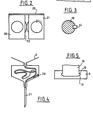
- - La figure 4 est une vue schématique à plus grande échelle du réservoir et des moyens de rappel du cathéter.
- - La figure 5 est une vue schématique à plus grande échelle des moyens d'association de la vis sans fin et du piston.
- - La figure 6 est une vué schématique en coupe par un plan axial illustrant la seconde partie d'un autre mode de réalisation de l'invention.
- - La figure 7 est une vue schématique illustrant un mode de réalisation des moyens limiteurs de couple selon l'invention.
- - La figure 8 est une vue schématique illustrant l'utilisation générale connue en soi d'une pompe d'injection de médicaments.
- - La figure 9 est une vue schématique en élévation du dispositif selon le deuxième mode de réalisation de l'invention.
- - La figure 10 est une vue schématique en élévation des moyens de régulation du dispositif selon le deuxième mode de réalisation de l'invention.
- - La figure 11 est une vue schématique sous forme de bloc diagramme des moyens de commande des moyens de régulation selon le deuxième mode de réalisation de l'invention.
- - Figure 1 is a schematic sectional view through an axial plane illustrating the device according to the first embodiment of the invention, the two parts of the device being dissociated from one another for better understanding.
- - Figure 2 is a schematic top view of the device according to the invention in order to show the cooperation of the two parts of the housing.
- - Figure 3 is a schematic cross-sectional view along line III-III of Figure 1.
- - Figure 4 is a schematic view on a larger scale of the reservoir and the catheter return means.
- - Figure 5 is a schematic view on a larger scale of the means of association of the worm and the piston.
- - Figure 6 is a schematic sectional view through an axial plane illustrating the second part of another embodiment of the invention.
- - Figure 7 is a schematic view illustrating an embodiment of the torque limiting means according to the invention.
- - Figure 8 is a schematic view illustrating the general use known per se of a drug injection pump.
- - Figure 9 is a schematic elevational view of the device according to the second embodiment of the invention.
- - Figure 10 is a schematic elevational view of the device regulating means according to the second embodiment of the invention.
- - Figure 11 is a schematic view in the form of a block diagram of the control means of the regulation means according to the second embodiment of the invention.
on décrira tout d'abord un premier mode de réalisation de l'invention en référence aux figures 1 à 7.a first embodiment of the invention will first be described with reference to FIGS. 1 to 7.
L'invention concerne un dispositif externe pour injecter un médicament ou autre, notamment de l'insuline, dans le corps humain, du type comportant un boîtier 1 portable (représenté seulement partiellement et schématiquement), une seringue 2 ayant un piston 3 montée amovible dans le boîtier 1, des moyens d'entraînement 4 du piston 3 à coulissement axial comprenant d'une part des moyens de stockage d'énergie 5 et des moyens automatiques d'entraînement linéaire 6 du piston 3 activés par l'énergie contenue dans les moyens de stockage d'énergie 5 et d'autre part des moyens manuels d'entraînement linéaire 7 à molette d'actionnement 16.The invention relates to an external device for injecting a medicament or other, in particular insulin, into the human body, of the type comprising a portable housing 1 (shown only partially and schematically), a
Le dispositif selon l'invention permet simultanément l'administration de doses instantanées ou bolus grâce aux moyens manuels 7 comme on le verra ultérieurement et d'autre part l'administration de doses continues à débit constant ou débit de base grâce aux moyens de stockage d'énergie 5 et aux moyens automatiques d'entraînement 6.The device according to the invention simultaneously allows the administration of instantaneous or bolus doses thanks to the manual means 7 as will be seen later and on the other hand the administration of continuous doses at constant flow or basic flow thanks to the storage means of
Selon l'invention, les moyens de stockage d'énergie 5 sont mécaniques, intégrés au boitier 1 et sont notamment constitués de moyens élastiques. Les moyens automatiques d'entraînement linéaire 6 sont également mécaniques. Les moyens automatiques d'entraînement sont constitués de moyens 9 de régulation du mouvement engendré par les moyens de stockage d'énergie 5, notamment par la détente des moyens élastiques 5, et de moyens mécaniques 8 de transmission du mouvement au piston 3.According to the invention, the energy storage means 5 are mechanical, integrated into the housing 1 and in particular consist of elastic means. The automatic linear drive means 6 are also mechanical. The automatic drive means consist of
Les moyens de stockage d'énergie 5 ont seulement pour fonction d'assurer la mise en mouvement des moyens moteurs automatiques d'entraînement linéaire 6 pour l'administration du débit de base tandis que, comme on l'a dit précédemment, l'administration du bolus est assurée seulement par l'actionnement des moyens manuels d'entraînement linéaire 7.The energy storage means 5 have only the function of ensuring the setting in motion of the automatic linear drive motor means 6 for the administration of the basic flow rate while, as said above, the administration of the bolus is ensured only by the actuation of the manual linear drive means 7.
Préférentiellement, les moyens de stockage d'énergie 5 sont constitués par un ressort notamment un ressort spiralé tandis que les moyens 9 de régulation comprennent un mouvement mécanique d'horlogerie 9, à échappement et balancier horizontal entraîné par le ressort spiral.Preferably, the energy storage means 5 are constituted by a spring, in particular a spiral spring, while the regulation means 9 comprise a
Les moyens d'entraînement linéaire 4 comprennent également une vis sans fin 10 coopérant avec un écrou 11. L'écrou 11 est mobile en rotation et bloqué axialement notamment par le boîtier 1. Il forme extérieurement un pignon mené. La vis sans fin 10 est principalement bloquée en rotation sous réserve de ce qui est mentionné ci-dessous et mobile axialement par rapport à un fourreau 15 monté pivotant dans le boîtier 1. Elle se termine, du côté de la seringue 2 par une saillie périphérique 12 coopérant de façon amovible et à force avec un logement périphérique 13 du piston 3. La saillie 12 et le logement constituent des moyens 12, 13 d'association rigide amovible de la vis 10 au piston 3.The linear drive means 4 also comprise an
La vis sans fin 10 est bloquée en rotation par rapport au fourreau 15 par au moins une clavette 14 s'étendant axialement. La clavette 14 est portée par le fourreau 15 monté pivotant dans le boîtier 1 et auquel est fixé la mollette d'actionnement manuel 16.The
Le fourreau 15 est bloqué en rotation par rapport au boîtier 1, de préférence dans un seul sens de rotation, par des moyens 30 de blocage à cliquet anti-retour. Il est ainsi bloqué dans un sens et libre dans l'autre sens. Préférentiellement, les moyens 8 de transmission comportent des organes amovibles et remplaçables de réglage de la vitesse.The
Les moyens 8 de transmission comportent en outre un axe 17 sur lequel est monté calé au moins un pignon moteur 18 coopérant avec l'écrou formant pignon mené 11. L'axe 17 est entraîné en rotation par le mouvement mécanique d'horlogerie 9.The transmission means 8 also comprise an
Préférentiellement, des moyens limiteurs de couple 19 sont interposés sur l'axe 17 en deux parties 17a, 17b, entre le pignon moteur 18 et le mouvement d'horlogerie 9. Ces moyens limiteurs de couple 19 permettent d'éviter la détérioration du cathéter 27 notamment lorsque celui-ci est bouché, par application d'une trop grande pression.Preferably, torque limiting means 19 are interposed on the
Les organes amovibles et remplaçables de réglage de la vitesse des moyens 8 de transmission sont constitués par exemple par plusieurs pignons moteurs 18 de différents diamètres susceptibles de coopérer chacun avec le pignon mené 11 et associés rigidement mais de façon amovible à l'axe 17 ou à une partie 17a de cet axe. Par exemple ces pignons moteurs 18 comportent un alésage axial muni d'une denture radiale (c'est-à-dire pour laquelle les dents ont leur hauteur radiale) susceptible de coopérence avec une denture radiale étendue le long de l'axe 17 et solidaire de cet axe 17 ou de la partie 17a.The removable and replaceable members for adjusting the speed of the transmission means 8 are constituted for example by
Le boitier 1 comporte préférentiellement deux parties 20, 21, la première partie 20 dans laquelle est monté l'axe 17, le (ou les) pignon(s) 18, les moyens limiteurs de coupe 19 et le mouvement d'horlogerie 9. Cette première partie 20 comporte une fenêtre latérale 22 d'accès aux dents du (ou des) pignon(s) 18 de laquelle saille une partie de la périphérie du (ou des) pignon(s) 18 pour permettre sa (leur) coopération avec l'autre pignon 11. Enfin, un bouton remontoir 23 est placé à l'extérieur de la première partie 20 pour permettre de remonter le ressort 5 du mouvement d'horlogerie 9.The housing 1 preferably comprises two
La seconde partie 21 comporte d'un côté un logement dans lequel est monté la seringue 2 et de l'autre côté, le fourreau 15 avec sa clavette 14, la vis sans fin 10 coopérant avec l'écrou 11 formant pignon mené. L'écrou 11 formant pignon mené saille d'une fenêtre 24 de cette seconde partie 21 pour permettre sa coopération avec le (ou les) pignon(s) 18.The
Des moyens d'association amovibles 25 représentés seulement schématiquement permettent d'associer l'un à l'autre de façon rigide mais amovible les deux parties 20 et 21 de manière que les pignons 11, 18 coopèrent l'un avec l'autre.Removable association means 25 shown only schematically make it possible to associate the two
Selon une autre caractéristique, il est prévu un logement d'extrémité 28 de la seconde partie 21 formant réservoir pour le cathéter 27, et des moyens de rappel 26 du cathéter 27 associé à la seringue 2 dans ce logement 28. Ces moyens de rappel 26 peuvent être constitués d'un ou plusieurs ressorts. En variante, ils sont constitués d'une molette à grand pas de vis intérieur montée à la sortie du logement 28, qui autorise l'extraction du cathéter 27 hors du logement 28, mais qui force le cathéter en sens contraire dans le logement 28 lorqu'on la tourne. Ces moyens 26 de rappel peuvent aussi être constitués d'un ressort spiral de rappel d'une bobine autour de laquelle le cathéter 27 s'enroule. Le logement 28 et les moyens 26 de rappel permettent d'éviter qu'une trop grande longueur de cathéter 27 ne reste sortie, tout en fournissant la longueur désirée de cathéter 27.According to another characteristic, there is provided an end housing 28 of the
On a représenté en figure 6 un autre mode de réalisation de la partie 21 du dispositif selon l'invention portant la seringue.FIG. 6 shows another embodiment of
Les moyens 30 de blocage du fourreau 15 par rapport au boltier, comportent au moins un cliquet 30 à ressort coopérant avec des dents périphériques radiales externes du fourreau 15 pour le bloquer en rotation dans un sens de rotation S1. Par contre ces moyens 30 de blocage laissent le fourreau 15 libre de tourner dans l'autre sens S2, lorsqu'on actionne manuellement la molette 16. Dans ce cas les bruits occasionnés par le cliquet 30 au passage de chaque dent du fourreau 15 permet à l'utilisateur de contrôler la rotation qu'il impose à la molette 16. Des numérotations ou graduations peuvent être prévues au voisinnage des dents sur le fourreau 15 ou sur la molette 16 pour permettre le contrôle visuel de la rotation par l'utilisateur. Les moyens 30 de blocage constituent donc également des moyens de dosage fin de la dose injectée manuellement.The means 30 for blocking the
Par ailleurs, le dispositif tel que représenté en figure 6 comporte également des moyens 31 limiteurs de la dose manuelle injectée, constitués d'une bague 32 extérieure au fourreau 15 et coopérant avec un filetage extérieur à grand pas de ce fourreau 15, de façon que la rotation du fourreau 15 dans le sens S2 induise le coulissement de la bague 32 vers une butée 33 du boîtier 1, simultanément et proportionellement au déplacement axial de la vis 10. Un pointeau 34 dont la pointe est rappelée par un ressort 35 dans les filets extérieurs du fourreau 15 permet de positionner la bague à la hauteur correspondant à la dose désirée. Le pointeau 34 traverse et coulisse dans une rainure 36 du boîtier 1 qui comporte avantageusement des graduations ou repères. Pour injecter une dose manuellement, l'utilisateur positionnera donc la bague 32 en tirant le pointeau 34 hors des filets du fourreau 15 puis en faisant coulisser la bague 32 de façon à placer le pointeau 34 en face du repère correspondant sur le boîtier à la dose désirée ou à la dose maximale. Ensuite l'utilisateur relâche le pointeau 34 qui coopére à nouveau avec les filets du fourreau 15, puis tourne la molette 16 dans le sens S2. La rotation sera stoppée quand la bague 32 arrive contre la butée 33, ce qui empêche l'injection d'une dose trop importante manuellement.Furthermore, the device as shown in FIG. 6 also comprises means 31 limiting the injected manual dose, consisting of a
Pendant la rotation manuelle de la molette 16, l'écrou 11 est bloqué par les moyens automatiques d'entraînement 7, notamment par les moyens 9 de régulation dont le mouvement d'horlogerie est contrarié.During the manual rotation of the
Lorsque le pignon moteur 18 coopére avec le pignon 1'1 pour entraîner automatiquement le piston 3, le fourreau 15 tend à tourner dans le sens S1 par rapport au boitier 1, et est donc bloqué par les moyens 30 de blocage. De ce fait la vis 10 est également bloquée en rotation et se déplace axialement.When the
Les moyens 19 limiteurs de couple représentés en figure 7 sont constitués d'une première couronne dentée 17a solidaire de l'axe 17 et des pignons moteurs 18, et d'une seconde couronne 17b dentée qui coopére avec la première couronne 17a. les dents des couronnes 17a,17b sont axiales, c'est-à-dire s'étendent selon leur hauteur sensiblement parallèlement à l'axe 17 et sont inclinées de façon à autoriser le glissement des couronnes 17a et 17b moyennant un déplacement axial de ces couronnes l'une par rapport à l'autre, si la couronne 17a solidaire des pignons moteurs 18 venait à se bloquer. La seconde couronne 17b porte un pignon 37 entraîné par le mouvement d'horlogerie 19. Cette couronne 17b et le pignon 37 sont traversés par l'axe 17 qui comporte à son extrémité une butée 38 coopérant avec un ressort de compression 39, qui lui, coopére avec le pignon 37 ou la couronne 17b pour rappeler cette couronne 17b contre la première couronne 17a avec une force donnée.The torque limiting means 19 shown in FIG. 7 consist of a first
Lorsque le couple transmis par les deux couronnes 17a, 17b dépasse une certaine valeur, la réaction axiale sur les dents des couronnes devient égale ou supérieure à la force de rappel du ressort 39, ce qui induit le déplacement axiale de la couronne 17b et le glissement des couronnes 17a, 17b l'une par rapport à l'autre. on prévoit avantageusement des moyens d'alarme de l'utilisateur en cas de glissement des couronnes 17a, 17b l'une par rapport à l'autre. Par exemple, le déplacement axial de la couronne 17b entraîne la libération du ressort 5 des moyens de stockage, et un contacteur déclenche une sonnerie quand se ressort est totalement détendu.When the torque transmitted by the two
On décrira maintenant un deuxième mode de réalisation de l'invention en référence àux figures 8 à 12.A second embodiment of the invention will now be described with reference to FIGS. 8 to 12.
L'invention concerne un dispositif 41 , destinée à être portée par un patient 42 et à cet effet portée par un holster 43 et à laquelle est associé un cathéter 44 dont l'extrémité 45 est introduite dans une veine du patient 42 .The invention relates to a
Le dispositif 41 est par exemple destinée à l'injection d'insuline, de produits anti-cancéreux, d'hormones ou tout autre produit approprié.The
Le dispositif 41 peut être notamment du type péristaltique , bien connu en soi et ne faisant pas directement l'objet de l'invention.The
Au dispositif 41 est associée, naturellement, une capacité de stockage 46 du médicament. Cette capacité 46 est constituée par exemple par une poche à fluide.
La pompe d'injection 41 comporte de façon connue en soi une entrée 47 ainsi qu'une sortie 48 destinées à être associées respectivement à la capacité 46 et au cathéter 44 ainsi que des moyens mobiles de transfert 49 interposés entre l'entrée et la sortie 47, 48. Ces moyens mobiles de transfert 49 comprennent : un organe mobile d'entraînement du médicament 50 , des premiers moyens d'entraînement 51, mobiles, associés à l'organe 50 et assurant son déplacement, et enfin une source d'énergie 52, associée aux premiers moyens d'entraînement 51 et propre à délivrer aux premiers moyens d'entraînement 51 la puissance énergétique nécessaire à leur fonctionnement et à leur entraînement.The
Dans le cas où ce dispositif 41 comporte une pompe péristaltique, l'organe mobile 50 est constitué par les galets périphériques mobiles d'une roue placée dans un carter de manière qu'un tube souple reliant l'entrée 47 et la sortie 48, c'est-à-dire la capacité 46 et le cathéter 44, soit placé entre le carter et les galets pour pouvoir être compressé par les galets définissant un volume connu de médicament en déplacement.In the case where this
Selon l'invention, la source d'énergie 52 est mécanique et le dispositif 41 comporte des moyens de régulation 53, électriques ou électroniques, associés aux premiers moyens d'entraînement 51 et propres à permettre le réglage du fonctionnement des premiers moyens d'entraînement 51.According to the invention, the
Ces moyens de régulation 53 comportent en premier lieu une source d'énergie électrique 54, en second lieu des seconds moyens d'entraînement 55, mobiles, auxquels est associée la source d'énergie électrique 54 et coopérant avec les premiers moyens d'entraînement 51 et, en troisième lieu, des moyens électriques ou électroniques de commande 56 des seconds moyens d'entraînement 55.These regulation means 53 comprise firstly a source of
Ainsi qu'on le verra ultérieurement, les seconds moyens d'entraînement 55 sont du type à fonctionnement tout ou rien intermittent selon un cycle de fonctionnement défini par les moyens de commande 56. Les seconds moyens d'entraînement 55 coopèrent fonctionnellement avec les premiers moyens d'entraînement 51 de manière que pendant les périodes de repos des seconds moyens d'entraînement 55, les premiers moyens d'entraînement 51 soient également maintenus au repos et que, au contraire, pendant la période de mouvement des seconds moyens d'entraînement 55, les premiers moyens d'entraînement 51 soient également en mouvement grâce à la source d'énergie mécanique 52 qui leur est associée. Comme indiqué précédemment, la succession des périodes de repos et de mouvement des seconds moyens d'entraînement 55 est déterminée par les moyens de commande 56.As will be seen later, the second drive means 55 are of the intermittent all-or-nothing type according to an operating cycle defined by the control means 56. The second drive means 55 functionally cooperate with the first means drive 51 so that during the rest periods of the second drive means 55, the first drive means 51 are also kept at rest and, on the contrary, during the period of movement of the second drive means 55 , the first drive means 51 are also in motion thanks to the
La source d'énergie mécanique 52 est constituée par exemple par un ressort, notamment spiralé, pouvant être bandé au moyen d'un remontoir 57. Les premiers moyens d'entraînement 51 sont également de type mécanique et comportent notamment d'une part un axe d'entrée 58 associé au ressort 52 et d'autre part, un axe de sortie 59 associé à l'organe mobile d'entrainement de médicaments 50. Compte-tenu de la structure du dispositif 41 et des caractéristiques quantitatives usuelles pour une telle pompe, on comprend que la source d'énergie mécanique 52 doive avoir une puissance suffisante pour permettre l'entraînement de l'organe mobile 50.The
Le cas échéant, et de façon connue en soi, un train d'engrenage 60 de démultiplications est interposé entre l'axe d'entrée 58 et l'axe de sortie 59.Where appropriate, and in a manner known per se, a gear train 60 of reduction gears is interposed between the
Dans une forme de réalisation préférentielle, les seconds moyens d'entraînement 55 sont calés sur l'axe de sortie 59 des premiers moyens d'entraînement sur lequel est également calé, dans le cas d'une pompe de type péristaltique, la roue à galets précédemment mentionnée.In a preferred embodiment, the second drive means 55 are wedged on the
Les seconds moyens d'entraînement 55 peuvent faire l'objet de nombreuses formes de réalisation, selon les nécessités. En particulier, ces seconds moyens d'entraînement 55 sont de type mécanique et peuvent comporter une roue dentée 61 calée sur l'axe de sortie 59 et présentant des dents périphériques 62 régulièrement disposées autour de l'axe; un levier 63 monté pivotant autour d'un axe 64, comportant à l'une de ses extrémités une ancre 65 coopérant avec les dents 62. Des moyens 66 permettent de faire pivoter le levier 63 autour de son axe 64 de manière que, grâce à la coopération de l'ancre 65 et des dents 62 de la roue dentée 61, la roue dentée 61 effectue des pivotements successifs de la valeur angulaire séparant deux dents successives et ceci à chaque mouvement alternatif de va et vient du levier 63.The second drive means 55 can be the subject of numerous embodiments, as required. In particular, these second drive means 55 are of the mechanical type and may include a
Les moyens 66 pour faire pivoter le levier 63 peuvent comporter un moteur électrique 67 de type pas-à-pas, sur l'axe de sortie 38 duquel est calée une roue 69 comportant au moins un ergot, saillie ou similaire 70 coopérant avec la partie extrême libre 71 du levier 63 opposée à 1 ancre 65.The means 66 for pivoting the
Egalement, préférentiellement, il peut être prévu des butées 72 limitant l'amplitude de pivotement du levier 63 et un ressort ou similaire sollicitant le levier 63 sur la roue 69.Also, preferably, stops 72 can be provided. limiting the amplitude of pivoting of the
La source d'énergie électrique 54 peut être constituée par une pile à courant continu notamment une pile au lithium de 3 volts. En effet, ainsi que cela résulte de la description précédente et des explications qui suivent, la puissance énergétique délivrée par la source d'énergie électrique 54 est faible puisqu'elle vise à permettre uniquement le fonctionnement des moyens de régulation 53, notamment le déplacement du levier 63. En conséquence, la source d'énergie électrique 54 peut être limitée en puissance et de longue durée, notamment non remplaçable.The
Les moyens de commande 56 des seconds moyens d'entraînement 55 peuvent comporter, par exemple un oscillateur 73 à fréquence réglable et un circuit de décomptage 74 susceptible de réaliser des trains d'impulsion selon des périodes déterminées et à cet effet, réglable au moyen de potentiomètres ou contacteurs à décade 75.The control means 56 of the second drive means 55 may comprise, for example an
Grâce à un actionnement des potentiomètres ou contacteurs à décade 75, il est possible de régler le train d'impulsion commandant le fonctionnement du moteur 67 donc, du levier 63 et, par conséquent, la rotation de la roue dentée 61. Lorsque la roue dentée 61 est libérée à l'occasion du mouvement de pivotement du levier 63, elle est entraînée par les premiers moyens d'entraînement 51.By actuating the potentiometers or decade switches 75, it is possible to adjust the pulse train controlling the operation of the
Ces contacteurs comportent des moyens permettant, sans modifier un réglage de débit préalablement fixé, d'assurer le fonctionnement continu du moteur 67 aussi longtemps qu'ils sont actionnés, permettant ainsi l'administration de doses instantanées.These contactors include means making it possible, without modifying a previously set flow adjustment, to ensure the continuous operation of the
Selon un autre mode de réalisation, l'administration de doses instantanées est obtenue par une action manuelle directe sur l'organe mobile d'entrainement.According to another embodiment, the administration of instant doses is obtained by direct manual action on the mobile drive member.
Claims (26)
Priority Applications (1)
| Application Number | Priority Date | Filing Date | Title |
|---|---|---|---|
| AT87401083T ATE84227T1 (en) | 1986-05-14 | 1987-05-14 | EXTERNAL MEDICATION INJECTION DEVICE. |
Applications Claiming Priority (4)
| Application Number | Priority Date | Filing Date | Title |
|---|---|---|---|
| FR8606940 | 1986-05-14 | ||
| FR8606940A FR2598624B1 (en) | 1986-05-14 | 1986-05-14 | EXTERNAL DEVICE FOR INJECTING MEDICAMENT OR THE LIKE |
| FR8610105 | 1986-07-10 | ||
| FR8610105A FR2601252B1 (en) | 1986-05-14 | 1986-07-10 | MEDICATION INJECTION PUMP. |
Publications (2)
| Publication Number | Publication Date |
|---|---|
| EP0246158A1 true EP0246158A1 (en) | 1987-11-19 |
| EP0246158B1 EP0246158B1 (en) | 1993-01-07 |
Family
ID=26225238
Family Applications (1)
| Application Number | Title | Priority Date | Filing Date |
|---|---|---|---|
| EP87401083A Expired - Lifetime EP0246158B1 (en) | 1986-05-14 | 1987-05-14 | External device for medical injection |
Country Status (4)
| Country | Link |
|---|---|
| EP (1) | EP0246158B1 (en) |
| AT (1) | ATE84227T1 (en) |
| DE (1) | DE3783392T2 (en) |
| FR (1) | FR2601252B1 (en) |
Cited By (12)
| Publication number | Priority date | Publication date | Assignee | Title |
|---|---|---|---|---|
| WO1994007562A1 (en) * | 1992-09-29 | 1994-04-14 | Alza Corporation | Highly controllable pulsatile delivery device |
| WO1994015660A1 (en) * | 1993-01-05 | 1994-07-21 | Berney Jean Claude | Powered-plunger infusion device |
| WO1996022117A2 (en) * | 1995-01-17 | 1996-07-25 | Johnson & Johnson Corporation | On-line drug delivery system in extracorporeal therapy |
| WO1996025965A1 (en) * | 1995-02-22 | 1996-08-29 | Mark Timothy Smith | Electronic syringe |
| US5685963A (en) * | 1994-10-31 | 1997-11-11 | Saes Pure Gas, Inc. | In situ getter pump system and method |
| US5911560A (en) * | 1994-10-31 | 1999-06-15 | Saes Pure Gas, Inc. | Getter pump module and system |
| US5972183A (en) * | 1994-10-31 | 1999-10-26 | Saes Getter S.P.A | Getter pump module and system |
| WO2000015280A1 (en) * | 1998-09-15 | 2000-03-23 | Njc Innovations | Devices with power-driven syringe for administering therapeutic substances |
| US6109880A (en) * | 1994-10-31 | 2000-08-29 | Saes Pure Gas, Inc. | Getter pump module and system including focus shields |
| US6142742A (en) * | 1994-10-31 | 2000-11-07 | Saes Pure Gas, Inc. | Getter pump module and system |
| US10213559B2 (en) | 2013-10-16 | 2019-02-26 | Novo Nordisk A/S | Drug delivery device with brake mechanism |
| CN113198068A (en) * | 2021-05-11 | 2021-08-03 | 广州联合丽拓生物科技有限公司 | Fly special needle that evenly easily pushes away |
Families Citing this family (1)
| Publication number | Priority date | Publication date | Assignee | Title |
|---|---|---|---|---|
| DE10240165A1 (en) * | 2002-08-30 | 2004-03-18 | Disetronic Licensing Ag | Dispensing unit for use in infusion pumps comprises reservoir for infusion liquid fitted with spring-loaded piston, toothed wheel cooperating with locking bar to prevent piston moving |
Citations (11)
| Publication number | Priority date | Publication date | Assignee | Title |
|---|---|---|---|---|
| DE600202C (en) | 1932-05-13 | 1934-07-17 | Hugh Titford Campkin | Device for limiting the stroke of plungers of dental injection syringes |
| US3384080A (en) | 1964-10-16 | 1968-05-21 | Us Catheter & Instr Corp | Portable spring powered infusion device having escapement means controlling speed ofinfusion |
| US3709636A (en) | 1970-09-04 | 1973-01-09 | Pall Corp | Timer |
| US3886938A (en) * | 1973-10-23 | 1975-06-03 | Scala Anthony | Power operated fluid infusion device |
| FR2282912A1 (en) | 1973-07-02 | 1976-03-26 | Kamen Dean | DEVICE FOR INJECTING MEDICINES |
| US3989913A (en) | 1974-10-11 | 1976-11-02 | Valleylab, Inc. | Intravenous feeding pump timer |
| FR2348709A1 (en) | 1976-04-23 | 1977-11-18 | Pistor Michel | MESOTHERAPIC TREATMENT PROCESS AND INJECTION DEVICE, FORMING AUTOMATIC MICRO-INJECTOR, INCLUDING APPLICATION |
| WO1982000589A1 (en) | 1980-08-21 | 1982-03-04 | D Whitney | Self-contained mechanical injector |
| FR2495942A1 (en) | 1980-12-12 | 1982-06-18 | Gazuit Electronic | Motorised jacking screw actuator for piston type medical syringe - has twin guide rods for crosshead contg. rapidly disengageable jacking nut |
| GB2109690A (en) | 1981-02-12 | 1983-06-08 | Robert Charles Turner | Dose metering plunger devices for use with syringes |
| WO1985001443A1 (en) | 1983-09-29 | 1985-04-11 | Beguin Edirene | Injection regulator |
Family Cites Families (1)
| Publication number | Priority date | Publication date | Assignee | Title |
|---|---|---|---|---|
| US4273122A (en) * | 1976-11-12 | 1981-06-16 | Whitney Douglass G | Self contained powered injection system |
-
1986
- 1986-07-10 FR FR8610105A patent/FR2601252B1/en not_active Expired - Lifetime
-
1987
- 1987-05-14 AT AT87401083T patent/ATE84227T1/en not_active IP Right Cessation
- 1987-05-14 DE DE3783392T patent/DE3783392T2/en not_active Expired - Fee Related
- 1987-05-14 EP EP87401083A patent/EP0246158B1/en not_active Expired - Lifetime
Patent Citations (11)
| Publication number | Priority date | Publication date | Assignee | Title |
|---|---|---|---|---|
| DE600202C (en) | 1932-05-13 | 1934-07-17 | Hugh Titford Campkin | Device for limiting the stroke of plungers of dental injection syringes |
| US3384080A (en) | 1964-10-16 | 1968-05-21 | Us Catheter & Instr Corp | Portable spring powered infusion device having escapement means controlling speed ofinfusion |
| US3709636A (en) | 1970-09-04 | 1973-01-09 | Pall Corp | Timer |
| FR2282912A1 (en) | 1973-07-02 | 1976-03-26 | Kamen Dean | DEVICE FOR INJECTING MEDICINES |
| US3886938A (en) * | 1973-10-23 | 1975-06-03 | Scala Anthony | Power operated fluid infusion device |
| US3989913A (en) | 1974-10-11 | 1976-11-02 | Valleylab, Inc. | Intravenous feeding pump timer |
| FR2348709A1 (en) | 1976-04-23 | 1977-11-18 | Pistor Michel | MESOTHERAPIC TREATMENT PROCESS AND INJECTION DEVICE, FORMING AUTOMATIC MICRO-INJECTOR, INCLUDING APPLICATION |
| WO1982000589A1 (en) | 1980-08-21 | 1982-03-04 | D Whitney | Self-contained mechanical injector |
| FR2495942A1 (en) | 1980-12-12 | 1982-06-18 | Gazuit Electronic | Motorised jacking screw actuator for piston type medical syringe - has twin guide rods for crosshead contg. rapidly disengageable jacking nut |
| GB2109690A (en) | 1981-02-12 | 1983-06-08 | Robert Charles Turner | Dose metering plunger devices for use with syringes |
| WO1985001443A1 (en) | 1983-09-29 | 1985-04-11 | Beguin Edirene | Injection regulator |
Cited By (22)
| Publication number | Priority date | Publication date | Assignee | Title |
|---|---|---|---|---|
| WO1994007562A1 (en) * | 1992-09-29 | 1994-04-14 | Alza Corporation | Highly controllable pulsatile delivery device |
| WO1994015660A1 (en) * | 1993-01-05 | 1994-07-21 | Berney Jean Claude | Powered-plunger infusion device |
| CH685461GA3 (en) * | 1993-01-05 | 1995-07-31 | Jean Claude Berney | Portable device for infusion of liquid therapeutic substances and assemblies comprising such a device. |
| US6043137A (en) * | 1994-10-31 | 2000-03-28 | Saes Getters S.P.A. | Getter pump module and system |
| US5993165A (en) * | 1994-10-31 | 1999-11-30 | Saes Pure Gas, Inc. | In Situ getter pump system and method |
| US6165328A (en) * | 1994-10-31 | 2000-12-26 | Saes Getters S.P.A. | Method for processing wafers with in situ gettering |
| US5685963A (en) * | 1994-10-31 | 1997-11-11 | Saes Pure Gas, Inc. | In situ getter pump system and method |
| US6142742A (en) * | 1994-10-31 | 2000-11-07 | Saes Pure Gas, Inc. | Getter pump module and system |
| US5879134A (en) * | 1994-10-31 | 1999-03-09 | Saes Pure Gas, Inc. | In situ getter pump system and method |
| US5911560A (en) * | 1994-10-31 | 1999-06-15 | Saes Pure Gas, Inc. | Getter pump module and system |
| US5972183A (en) * | 1994-10-31 | 1999-10-26 | Saes Getter S.P.A | Getter pump module and system |
| US5980213A (en) * | 1994-10-31 | 1999-11-09 | Saes Getters S.P.A. | Getter pump module and system |
| US6109880A (en) * | 1994-10-31 | 2000-08-29 | Saes Pure Gas, Inc. | Getter pump module and system including focus shields |
| US5997255A (en) * | 1994-10-31 | 1999-12-07 | Saes Getters S.P.A. | Method for pumping a chamber using an in situ getter pump |
| WO1996022117A2 (en) * | 1995-01-17 | 1996-07-25 | Johnson & Johnson Corporation | On-line drug delivery system in extracorporeal therapy |
| WO1996022117A3 (en) * | 1995-01-17 | 1996-11-07 | Johnson & Johnson Corp | On-line drug delivery system in extracorporeal therapy |
| WO1996025965A1 (en) * | 1995-02-22 | 1996-08-29 | Mark Timothy Smith | Electronic syringe |
| US5690618A (en) * | 1995-02-22 | 1997-11-25 | Mark Timothy Smith | Electronic syringe |
| WO2000015280A1 (en) * | 1998-09-15 | 2000-03-23 | Njc Innovations | Devices with power-driven syringe for administering therapeutic substances |
| US10213559B2 (en) | 2013-10-16 | 2019-02-26 | Novo Nordisk A/S | Drug delivery device with brake mechanism |
| CN113198068A (en) * | 2021-05-11 | 2021-08-03 | 广州联合丽拓生物科技有限公司 | Fly special needle that evenly easily pushes away |
| CN113198068B (en) * | 2021-05-11 | 2022-04-15 | 广州联合丽拓生物科技有限公司 | Fly special needle that evenly easily pushes away |
Also Published As
| Publication number | Publication date |
|---|---|
| FR2601252B1 (en) | 1990-06-08 |
| EP0246158B1 (en) | 1993-01-07 |
| FR2601252A1 (en) | 1988-01-15 |
| ATE84227T1 (en) | 1993-01-15 |
| DE3783392D1 (en) | 1993-02-18 |
| DE3783392T2 (en) | 1996-09-19 |
Similar Documents
| Publication | Publication Date | Title |
|---|---|---|
| EP0246158B1 (en) | External device for medical injection | |
| EP0577538B1 (en) | Trigger actuated electromechanical injection device for medical or veterinary purposes | |
| EP0396536B1 (en) | Syringe-pushing device for ambulant administration of parenteral injections, with flow rate governed by the contents of the syringe and method of control thereof | |
| US4921487A (en) | External device for injecting medicine | |
| EP0140727B1 (en) | Implantable fluid injection device | |
| WO1997000091A1 (en) | Linear-transmission syringe plunger | |
| EP0927306B1 (en) | Portable peristaltic pump | |
| EP0388787B1 (en) | Miniature peristaltic pump | |
| FR2572288A1 (en) | INFUSION PUMP | |
| EP0927307A1 (en) | Miniature peristaltic pump | |
| FR2690621A1 (en) | Friction-free infusion pump system. | |
| WO2002061281A1 (en) | Occlusion detector for rotary peristaltic pump | |
| WO1999021597A1 (en) | Device for administering therapeutic substances with power-operated syringe | |
| WO1987007843A1 (en) | Monostroke syringe pusher for automatic parenteral injections with servo-control and programming | |
| WO2015044102A1 (en) | Injection pen with vibration function for cartridge of same for removing air bubbles | |
| WO2021224388A1 (en) | Needle insertion device for distributing a product in a site | |
| FR2598624A1 (en) | External device for injecting a medication or the like | |
| CH710320A2 (en) | Timepiece comprising a source of mechanical energy and a control member. | |
| FR2753103A1 (en) | MINIATURE PERISTALTIC PUMP FOR MEDICAL USE | |
| EP0157812A1 (en) | Injection regulator | |
| FR3093437A1 (en) | Device for inserting a needle for dispensing a product in a site | |
| FR2778338A1 (en) | INJECTION DEVICE WITH CONTROLLED FLOW AND AMBULATORY OF A MEDICINAL PRODUCT IN LIQUID FORM | |
| EP0220995A1 (en) | Electrically driven autonomous shears | |
| FR2544987A1 (en) | Semi-automatic insulin pump for patient in bed | |
| WO2022049341A1 (en) | Device for dispensing a fluid product |
Legal Events
| Date | Code | Title | Description |
|---|---|---|---|
| PUAI | Public reference made under article 153(3) epc to a published international application that has entered the european phase |
Free format text: ORIGINAL CODE: 0009012 |
|
| AK | Designated contracting states |
Kind code of ref document: A1 Designated state(s): AT BE CH DE ES FR GB GR IT LI LU NL SE |
|
| 17P | Request for examination filed |
Effective date: 19880227 |
|
| RAP1 | Party data changed (applicant data changed or rights of an application transferred) |
Owner name: BUFFET, JEAN-PAUL Owner name: COMPAGNIE FINANCIERE SAINT-NICOLAS Owner name: BUFFET, JACQUES |
|
| 17Q | First examination report despatched |
Effective date: 19890929 |
|
| GRAA | (expected) grant |
Free format text: ORIGINAL CODE: 0009210 |
|
| AK | Designated contracting states |
Kind code of ref document: B1 Designated state(s): AT BE CH DE ES FR GB GR IT LI LU NL SE |
|
| PG25 | Lapsed in a contracting state [announced via postgrant information from national office to epo] |
Ref country code: IT Free format text: LAPSE BECAUSE OF FAILURE TO SUBMIT A TRANSLATION OF THE DESCRIPTION OR TO PAY THE FEE WITHIN THE PRE;WARNING: LAPSES OF ITALIAN PATENTS WITH EFFECTIVE DATE BEFORE 2007 MAY HAVE OCCURRED AT ANY TIME BEFORE 2007. THE CORRECT EFFECTIVE DATE MAY BE DIFFERENT FROM THE ONE RECORDED.SCRIBED TIME-LIMIT Effective date: 19930107 Ref country code: SE Effective date: 19930107 Ref country code: NL Effective date: 19930107 Ref country code: AT Effective date: 19930107 Ref country code: GR Free format text: LAPSE BECAUSE OF FAILURE TO SUBMIT A TRANSLATION OF THE DESCRIPTION OR TO PAY THE FEE WITHIN THE PRESCRIBED TIME-LIMIT Effective date: 19930107 Ref country code: GB Effective date: 19930107 |
|
| REF | Corresponds to: |
Ref document number: 84227 Country of ref document: AT Date of ref document: 19930115 Kind code of ref document: T |
|
| REF | Corresponds to: |
Ref document number: 3783392 Country of ref document: DE Date of ref document: 19930218 |
|
| PG25 | Lapsed in a contracting state [announced via postgrant information from national office to epo] |
Ref country code: ES Free format text: LAPSE BECAUSE OF FAILURE TO SUBMIT A TRANSLATION OF THE DESCRIPTION OR TO PAY THE FEE WITHIN THE PRESCRIBED TIME-LIMIT Effective date: 19930418 |
|
| PG25 | Lapsed in a contracting state [announced via postgrant information from national office to epo] |
Ref country code: CH Effective date: 19930531 Ref country code: LU Free format text: LAPSE BECAUSE OF NON-PAYMENT OF DUE FEES Effective date: 19930531 Ref country code: LI Effective date: 19930531 Ref country code: BE Effective date: 19930531 |
|
| NLV1 | Nl: lapsed or annulled due to failure to fulfill the requirements of art. 29p and 29m of the patents act | ||
| GBV | Gb: ep patent (uk) treated as always having been void in accordance with gb section 77(7)/1977 [no translation filed] |
Effective date: 19930107 |
|
| PLBE | No opposition filed within time limit |
Free format text: ORIGINAL CODE: 0009261 |
|
| STAA | Information on the status of an ep patent application or granted ep patent |
Free format text: STATUS: NO OPPOSITION FILED WITHIN TIME LIMIT |
|
| BERE | Be: lapsed |
Owner name: BUFFET JACQUES Effective date: 19930531 Owner name: BUFFET JEAN-PAUL Effective date: 19930531 Owner name: CIE FINANCIERE SAINT-NICOLAS Effective date: 19930531 |
|
| 26N | No opposition filed | ||
| REG | Reference to a national code |
Ref country code: CH Ref legal event code: AUV Free format text: LE BREVET CI-DESSUS EST TOMBE EN DECHEANCE, FAUTE DE PAIEMENT, DE LA 7E ANNUITE. Ref country code: CH Ref legal event code: PL |
|
| PGFP | Annual fee paid to national office [announced via postgrant information from national office to epo] |
Ref country code: FR Payment date: 19980529 Year of fee payment: 12 |
|
| PGFP | Annual fee paid to national office [announced via postgrant information from national office to epo] |
Ref country code: DE Payment date: 19980721 Year of fee payment: 12 |
|
| PG25 | Lapsed in a contracting state [announced via postgrant information from national office to epo] |
Ref country code: FR Free format text: LAPSE BECAUSE OF NON-PAYMENT OF DUE FEES Effective date: 20000131 |
|
| PG25 | Lapsed in a contracting state [announced via postgrant information from national office to epo] |
Ref country code: DE Free format text: LAPSE BECAUSE OF NON-PAYMENT OF DUE FEES Effective date: 20000301 |
|
| REG | Reference to a national code |
Ref country code: FR Ref legal event code: ST |
|
| APAH | Appeal reference modified |
Free format text: ORIGINAL CODE: EPIDOSCREFNO |