EP0246218A2 - Fault-tolerant data processing system - Google Patents
Fault-tolerant data processing system Download PDFInfo
- Publication number
- EP0246218A2 EP0246218A2 EP87890089A EP87890089A EP0246218A2 EP 0246218 A2 EP0246218 A2 EP 0246218A2 EP 87890089 A EP87890089 A EP 87890089A EP 87890089 A EP87890089 A EP 87890089A EP 0246218 A2 EP0246218 A2 EP 0246218A2
- Authority
- EP
- European Patent Office
- Prior art keywords
- signals
- fault
- voter
- processing system
- input
- Prior art date
- Legal status (The legal status is an assumption and is not a legal conclusion. Google has not performed a legal analysis and makes no representation as to the accuracy of the status listed.)
- Granted
Links
Images

Classifications
-
- G—PHYSICS
- G06—COMPUTING; CALCULATING OR COUNTING
- G06F—ELECTRIC DIGITAL DATA PROCESSING
- G06F11/00—Error detection; Error correction; Monitoring
- G06F11/07—Responding to the occurrence of a fault, e.g. fault tolerance
- G06F11/16—Error detection or correction of the data by redundancy in hardware
- G06F11/18—Error detection or correction of the data by redundancy in hardware using passive fault-masking of the redundant circuits
- G06F11/182—Error detection or correction of the data by redundancy in hardware using passive fault-masking of the redundant circuits based on mutual exchange of the output between redundant processing components
-
- G—PHYSICS
- G06—COMPUTING; CALCULATING OR COUNTING
- G06F—ELECTRIC DIGITAL DATA PROCESSING
- G06F11/00—Error detection; Error correction; Monitoring
- G06F11/07—Responding to the occurrence of a fault, e.g. fault tolerance
- G06F11/14—Error detection or correction of the data by redundancy in operation
- G06F11/1402—Saving, restoring, recovering or retrying
- G06F11/1415—Saving, restoring, recovering or retrying at system level
- G06F11/1443—Transmit or communication errors
-
- G—PHYSICS
- G06—COMPUTING; CALCULATING OR COUNTING
- G06F—ELECTRIC DIGITAL DATA PROCESSING
- G06F11/00—Error detection; Error correction; Monitoring
- G06F11/07—Responding to the occurrence of a fault, e.g. fault tolerance
- G06F11/16—Error detection or correction of the data by redundancy in hardware
- G06F11/1675—Temporal synchronisation or re-synchronisation of redundant processing components
- G06F11/1687—Temporal synchronisation or re-synchronisation of redundant processing components at event level, e.g. by interrupt or result of polling
-
- G—PHYSICS
- G06—COMPUTING; CALCULATING OR COUNTING
- G06F—ELECTRIC DIGITAL DATA PROCESSING
- G06F11/00—Error detection; Error correction; Monitoring
- G06F11/07—Responding to the occurrence of a fault, e.g. fault tolerance
- G06F11/16—Error detection or correction of the data by redundancy in hardware
- G06F11/18—Error detection or correction of the data by redundancy in hardware using passive fault-masking of the redundant circuits
- G06F11/187—Voting techniques
-
- G—PHYSICS
- G06—COMPUTING; CALCULATING OR COUNTING
- G06F—ELECTRIC DIGITAL DATA PROCESSING
- G06F2201/00—Indexing scheme relating to error detection, to error correction, and to monitoring
- G06F2201/83—Indexing scheme relating to error detection, to error correction, and to monitoring the solution involving signatures
Definitions
- the invention relates to a fault-tolerant data processing system with a group of computer units that deliver and process the same binary data signals and at least one logical decision unit (voter) that votes on the data signals of the group.
- Fault-tolerant data processing systems can be found, for example, in US Pat. No. 4,375,683.
- a so-called triple-modular redundancy is used, in each case three computers being connected to a common logical decision unit.
- Such circuit arrangements primarily serve to achieve higher system reliability in the event of unforeseeable hardware failures.
- the logical decision unit works on the basis of a majority vote and the system can still be operated appropriately if a computer unit of the three units combined into a group emits an incorrect signal.
- the logical decision unit forms a majority decision in favor of the identical signals and this majority result is further processed in data processing.
- a high degree of decentralized data processing is additionally provided for process control systems that naturally record decentralized events, such as for railway safety systems.
- the invention further aims to ensure a high degree of reliability and fault tolerance even in the case of non-periodic and indeterministic events.
- the invention consists essentially in the fact that a plurality of groups with at least three computer units which supply or process data signals are connected to one another via data channels and that the voters of one group are connected to the voters of other groups via data or signal lines.
- This type of connection makes it possible to dispense with a global time base and to carry out synchronizations, for example with the aid of a relative time base, for example by exclusively measuring time differences.
- Process processing can also be carried out according to a selected priority-controlled method based on the selected networking.
- a system-wide time base for synchronization of the process processing can be omitted and there is also no need for a time grid for the execution of processes.
- the connection of the individual computer units supplying or processing data signals to one another can be achieved by serial point-to-point connections can be designed as a network.
- each computer unit supplying or processing data signals has at least one voter for the decision on the error-free nature of input and / or output signals, the main result of which occurs in the case of non-cyclic working methods and in the absence of a global time base Problems with the order of the individual messages can be effectively mastered by the fact that each computer unit supplying or processing data signals contains a sequence voter for deciding on the correct order of the signals to be processed.
- the fault tolerance can be increased by always assuming that when all the individual computer units in a group result in different sequences, it is essentially a matter of simultaneous events and therefore a priority or an order of the messages, also on the basis of this a random order, which, however, must be chosen uniformly for the subsequent operations, can be continued here.
- redundancy In addition to error detection and triple-modular redundancy, other forms of redundancy are also desirable in a fault-tolerant data processing system for non-periodic event-controlled systems, in addition to active redundancy, in which several computer units supplying or processing data signals are simultaneously involved in fulfilling the same task
- a passive redundancy can be provided, in which a computer unit supplying or processing redundant data signals is only switched on when it is to replace a failed computer unit that supplies or processes data signals during operation.
- the main advantage of the networking according to the invention is that the transmission of data or signals or messages between individual groups can take place serially, which of course significantly reduces the line effort.
- the possibility of serial transmission is primarily due to the existence of the sequence voter, which in turn corrects any change in the sequence of the individual signals or messages that may have occurred in the case of non-periodic, deterministic events.
- the connections or links between the individual computer units are bidirectional, so that a complete meshing and a complete exchange about the processes in the individual groups of the fault-tolerant data processing system take place with one another.
- the networking can be carried out in the form of a cascading or contain branches or mergers (convergences or divergences).
- the fault-tolerant data processing system of the present invention it is possible to equip computer units supplying or processing data signals with data inputs for sensor signals or input or output processors, as a result of which the fault-tolerant data processing system also achieves fault tolerance with respect to the sensor signals or faulty sensor signals.
- the inputs and / or outputs of the groups are advantageously connected to peripheral processors which are responsible for the further process control.
- the networking is advantageously carried out in such a way that the signals of the voters for input signals are the sequence voters are forwardable.
- the sequence voter decides on the sequence of the input signals and these input signals are then transferred in this sequence to the process processing and the result is then made available to the output voter.
- the inner logic of the decision-making units or voters for the input or output signals is advantageously designed in such a way that the input and / or output voters pass on the signals with a majority given in relation to the total number of channels.
- the fault-tolerant data processing system is also suitable for connecting single-channel peripheral devices, but in order to maintain the fault tolerance in interactive single-channel peripheral devices, the arrangement is such that an interface is provided for connecting these devices, which has a voter for voting on the signals of a group contains which are to be forwarded to the peripheral device and the signals to be supplied by the peripheral device to the group are reproduced in accordance with the number of units in the group.
- a major advantage of the system networking according to the invention can be seen in the possible serial connection between the individual groups or units, this networking being able to be carried out with little wiring effort.
- the fault tolerance is ensured in that decisions can be made about the sequence of the individual signals or messages within the same network.
- VOTRICS Vting TRiple modular Computing System
- FIG. 1 shows a general representation of a VOTRICS system
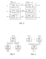
- FIG. 2 the cascading of VOTRICS nodes
- FIG. 3 the convergence of VOTRICS nodes
- FIG. 4 a divergence of VOTRICS nodes
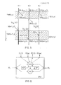
- FIG. 5 the temporal Uncertainty in the transmission of a triad of messages between two cascaded VOTRICS systems
- FIG. 6 shows the interaction of the voting functions in one computing unit
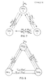
- FIG. 8 virtual duplication of the voting links by using redundancy in the time domain .
- a VOTRICS network consists of any network of one or more VOTRICS nodes, each of which forms an autonomous fault-tolerant subsystem.
- a VOTRICS node consists of three independent computer units of the same configuration - so-called Smallest Replaceable Units (SRU) - which are loosely meshed with one another by serial bidirectional voting links VL.
- SRU Smallest Replaceable Units
- Each SRU is connected to the environment through one or more serial input and output channels IC, OC.
- Fig. L shows the most general arrangement of such a system consisting of SRU (al) ... SRU (an), which work together in active redundancy and SRU (pl) ... SRU (pn) in passive redundancy (standby).
- a prerequisite for the successful application of active redundancy is an efficient voting mechanism, which allows the results and the behavior of the computers working in active redundancy to be compared continuously and under real-time conditions.
- the voting mechanism i.e. to be able to tolerate the error (error masking)
- at least 2N + 1 results determined independently of one another are necessary.
- active redundancy Simultaneous determination of the results, once per computer
- at least three computers are necessary to be able to tolerate an error.
- TMR Triple Modular Redundancy
- Special voting hardware is used in many of the fault-tolerant systems mentioned in the literature. If this voting hardware is carried out simply, it worsens the mean time between failures (MTBF) of the TMR system. The failure of the voting hardware results in a total failure. Solutions with redundant voting hardware are also known (see for example: AL Hopkins Jr., FTMP - A Highly Reliable Fault-Tolerant Multi- processor for Aircraft, Proc. Of the IEEE, Vol 66 No. lo. Pp l22l - l239, Oct l978 ). Although these provide a comparatively better reliability, they require considerable additional hardware expenditure.
- the voting function is therefore divided between the individual computer units (SRUs) of the system.
- SRUs computer units
- this can be done by software voters in everyone individual computing unit.
- the architecture described below allows any combination of SRU's in active and / or passive redundancy, so it can be flexibly adapted to the required reliability or availability.
- Lamport & PM Melliar-Smith Synchronizing Clocks in the Presence of Faults, Journal of the ACM, Vol 32 No l, pp. 52 - 78, Jan l985).
- Time measurements in VOTRICS are only carried out using a relative time base - only time differences are measured, ie the inevitable drift of the hardware timers cannot have any effect.
- process scheduling is not carried out in a fixed, periodic time schedule, but according to a simple, priority-controlled FIFO procedure. All actions take place on the basis of (stochastic) external and internal events. By eliminating the coupling of the scheduling to a system-wide time base, it is necessary to use suitable synchronization measures to coordinate the scheduling activities among the SRUs working in active redundancy.
- Both VOTRICS nodes and the computer units SRU within a node are networked with one another by serial point-to-point connections.
- An alternative to this would be computer couplings via redundant "broadcast buses".
- the point-to-point connections provide a simple method to limit the spread of errors, since only two units of SRU can be affected by a link error.
- Each VOTRICS node forms a fault-tolerant subsystem.
- An essential goal of this concept is the possibility of being able to build up a distributed computer network from several such subsystems. For this it is necessary to connect VOTRICS nodes with each other.
- the coupling of two VOTRICS nodes takes place through three point-to-point connections (paired connection of two neighboring SRUs). In this way, any network topology can be created by cascading and branching.
- the node TMR (n, x) (node x of level n) and the node TMR (n + l, y) (node y of level n + l) are via channels K1, K2 and K3 cascaded.
- the three computer units SRU (1, 2, 3) are completely intermeshed within each node.
- FIG. 3 shows the convergence in a VOTRICS arrangement.
- This type of message synchronization corresponds to the principle of event control, according to which all actions of application processes can only be triggered by messages.
- the CHILL application process is not interrupt-controlled; Interrupts are handled by the operating system and are only used to handle serial communication between SRUs.
- FIG. 5 shows the uncertainty in time during the transmission of a message triad between two cascaded VOTRICS systems.
- Communication between neighboring VOTRICS nodes takes place via 'message triads': three identical messages are exchanged between the three SRU pairs of two neighboring VOTRICS nodes via the three connecting lines. Due to the different processing times in the SRUs of the sending and receiving VOTRICS nodes and also due to possible differences in the transmission times (serial transmission method), the messages of a triad arrive with a time uncertainty in the receiver processes.
- the three computer units SRU (n, x, l) present in the node TMR (n, x) (from FIG. 2) send SRU (n, x, 2) and SRU (n, x, 3) on the channels Kl, K2, K3 the output messages OM (n, x, l), OM (n, x, 2) and OM (n, x, 3) from.
- the max. Output blur Uamax (n, x) is given in this case by the time interval between the output messages OM (n, x, l) and OM (n, x, 2).
- the transmission sharpness Utue (n, x - n + l, y) is TUe2 minus TUel in the present example.
- the receiver receives the same sequence of messages on every single input channel of a triad (no transmission errors). If several input channels are connected to each SRU (convergence, see FIG. 4), this no longer applies to the sum of the messages received from these channels.
- the synchronization algorithm used in VOTRICS to solve this problem is based on the principle of a distributed 'sequence voting' on the sequence of input messages passed on from the individual SRUs of a TMR system to the application processes, which will be described in a later section.
- timeout messages Since the clocks are not synchronized and the application processes run with considerable time blurring in the three computer units, the sequence of the timeout messages is not necessarily identical in all three units. However, the timeout messages generated by the operating system can be viewed as an additional input channel, and therefore identical timeout messages are sent to the application processes to all computer units.
- the voters can be used for a wide variety of tasks, the following basic functions are carried out by each voter: error detection, error masking and synchronization.
- sequence- Voting and input / output voting differentiated.
- each computer unit SRU there is an input / output voter IOV which forms a voting triad with its neighboring voters by means of voting links VL.
- This voter now has to vote on all incoming or outgoing message triads of a VOTRICS node.
- the source for incoming message triads are the input channels ICl ... ICn and the timeout handler TOH of the operating system.
- the outgoing messages which are processed by the AP application processor leave the VOTRICS node via the output channels OCl ... OCm after they have been recognized as correct by the input-output voter.
- the input message sequences generated by the input / output voters are different in each SRU, although the amount of messages in each sequence is the same. All input message triads that were accepted as correct during the input voting are therefore redirected to the sequence voter SV, where a uniform sequence of the messages is produced and then passed on to the application process.
- Voters have the task of recognizing error situations and masking them if possible, but cannot take system-wide measures such as Stop your own SRU, recovery etc.
- EMP 'Error Monitoring Process'
- each application process can start one or more independent time monitoring. After such a timeout has expired, the process receives a message from the operating system that it specified when the timeout was started.
- timeout expires in one SRU and not in the other two (or vice versa). Although this is not an error situation, it is not desirable to deal with such situations in the sequence voter (the sequence voter would be a lot more complex if the timeout message were handled specially).
- the timeout signals are therefore forwarded to the input / output voter, who then ensures that only complete timeout message triads are forwarded to the sequence voter triad.
- the input / output voting triad also votes on all signals that leave the VOTRICS node.
- the purpose of the output voting is to identify errors in the neighboring units, to mask the errors and to provide the output triad with a uniform identifier.
- the sequence of signals leaves the Votrics node in the same sequence as it was created by the application process.
- each concrete input / output vote is only carried out via three redundant objects (in most cases signal triads), the input / output votes must process the sequences of such triads correctly. This results in a few boundary conditions: -The triads of a logical channel (e.g. an input channel) must be output in the same order in which they arrived. Since a triplicated channel generates three identical signal sequences, a uniform sequence is defined in the signal triads. -The sequence in which signals are transmitted from different logical channels is arbitrary. - A faulty triad must not affect the processing of other triads in the same voter.
- Triads from different logical channels should therefore be processed and transmitted in parallel, while successive triads on a single logical channel must be transmitted sequentially.
- the triads can influence each other in different ways, namely through -Triad overlap on a single logical channel: If the time interval between the arrival of triads is smaller than the time blur within the three signals of the triad, it can happen, for example, that the signal arrives later on the "own" input channel of the voter than one or both Voting signals one subsequent triad (the incept signals which the neighboring voters receive and pass on). In the case of a "defective" triad, ie a triad with an incorrect or non-existent signal, much more complex situations can arise.
- Channel overlap The input / output voter has to process triads from several logical input channels (at least from a physical input channel and a timeout handler). The signals of such triads can arrive in any order.
- the input / output voter must therefore be able to process any combination of triad and channel overlap.
- the basic principle of the distributed voting used here is that each voter passes on the content of an input message received by him to his partners by sending 'voting messages'.
- An output of the voting result (e.g. in the case of IOV transfer to the sequence voter) takes place exclusively on the basis of a 2 out of 3 majority decision (commitment).
- This voting algorithm relates to a news triad.
- a voter can vote across multiple triads simultaneously to search for triad or channel overlap, however the sequence of commitments across each logical channel must match the input sequence of that logical channel.
- sequence voting will now be described.
- the task of the sequence voter triad is the coordinated forwarding of a uniform input message sequence to the application processes of each SRU.
- Each sequence voter receives the message sequences generated by the IOV and unites them in coordination with his neighbors to a resulting news sequence accepted by all three sequence voters.
- the correctly ordered signals which are identical in each computer unit (SRU), are then passed on to the application processes in order to synchronize their processes.
- the sequence voter like other voters, performs error masking. However, if a sequence voter detects an error, this always means a critical situation. It is very likely that the voter who sent the message is defective. If this is an error in your own SRU, this is subsequently stopped by the 'Error Monitoring Process'.
- voting links form the only connections between the SRUs of a VOTRICS system. In order to achieve maximum independence of the individual error behavior of the SRUs of a VOTRICS system, it must be prevented that neighboring SRUs can export or import errors via the voting links.
- the resulting arrangement of the voting links for the computer unit SRUk can be seen from FIG.
- the voter of this unit accordingly receives the above-mentioned voting messages from the input channel ICk and the voting links VLjk from the computer unit SRUj and VLik from the computer unit SRUi and from the additional virtual voting links VLjk ⁇ from the computer unit SRUj via SRUi and Vlik from the computer unit SRUi via SRUj.
- VMij VMik.
- VMij is forwarded from SRUj to SRUk (VMik), VMik from SRUk to SRUj (VMij ⁇ );
- Both SRUj and SRUk can independently determine by checking the conditions (VMij-VMij) or (VMik VMik ⁇ ) that SRUi is lying. In both cases, the condition is not met.
- Each SRU protects the voting messages it produces with an individual, unique signature.
- each SRU only knows its own coding algorithm.
- ENCODEi (VMix) is only known to SRUi.
- Each voting message is provided with its individual signature by the source SRU.
- no signature is applied.
- the destination SRU can use the decoding algorithm known to it and thus check whether the message has been damaged on the way through the neighboring SRU.
- SRUi produces VMij and VMik. Before sending to SRU j or SRUk, the signature is applied, specifically for VMij: “ENCODEi (VMij)" and for VMik: “ENCODEi (VMik)”. SRUj duplicates VMij and sends (without applying its own signature VMik to SRUk, but at the same time SRUj also performs the decoding functions for its own message (DECODEi (VMij)).
- DECODEi VMij
- SRUk receives VMik and VMik ⁇ and executes the decoding function DECODE: (VMik) and DECODE (VMik ⁇ ); SRUk also produces a VMij (but without its own signature) and sends it to SRUj where it is received, decrypted with DECODE (VMij ⁇ ) and compared with the decrypted VMij.
- the timing of the system in the event of a failed voting link is also improved in such a way that in this situation the input blur no longer enters into the commitment blur during voting.
Abstract
Description
Die Erfindung bezieht sich auf ein fehlertolerantes Datenverarbeitungssystem mit einer Gruppe von gleiche binäre Datensignale liefernden und verarbeitenden Rechnereinheiten und wenigstens einer logischen Entscheidungseinheit (Voter), welche über die Datensignale der Gruppe abstimmt.The invention relates to a fault-tolerant data processing system with a group of computer units that deliver and process the same binary data signals and at least one logical decision unit (voter) that votes on the data signals of the group.
Fehlertolerante Datenverarbeitungssysteme sind beispielsweise der US-PS 4 375 683 zu entnehmen. Bei dieser bekannten Ausbildung wird eine sogenannte tripelmodulare Redundanz angewandt, wobei jeweils drei Rechner mit einer gemeinsamen logischen Entscheidungseinheit verbunden sind. Derartige Schaltungsanordnungen dienen in erster Linie der Erzielung einer höheren Systemzuverlässigkeit bei nicht vorhersehbaren Hardwareausfällen. Bei dieser bekannten Einrichtung arbeitet die logische Entscheidungseinheit auf der Basis einer Mehrheitsabstimmung und das System kann auch dann noch sinnvoll weiterbetrieben werden, wenn eine Rechnereinheit der drei zu einer Gruppe zusammengefaßten Einheiten ein fehlerhaftes Signal abgibt. Die logische Entscheidungseinheit bildet bei zwei gleichartigen Signalen, welche von einem dritten Signal abweichen, eine Mehrheitsentscheidung zugunsten der gleichartigen Signale und dieses Mehrheitsergebnis wird in der Datenverarbeitung weiterverarbeitet.Fault-tolerant data processing systems can be found, for example, in US Pat. No. 4,375,683. In this known design, a so-called triple-modular redundancy is used, in each case three computers being connected to a common logical decision unit. Such circuit arrangements primarily serve to achieve higher system reliability in the event of unforeseeable hardware failures. In this known device, the logical decision unit works on the basis of a majority vote and the system can still be operated appropriately if a computer unit of the three units combined into a group emits an incorrect signal. In the case of two identical signals which differ from a third signal, the logical decision unit forms a majority decision in favor of the identical signals and this majority result is further processed in data processing.
Insbesondere für den Ablauf in komplexen Datenverarbeitungssystemen, bei welchen nichtperiodische und indeterministische Ereignisse verarbeitet werden sollen und ein ereignisgesteuertes System geschaffen werden soll, bestehen große Probleme bei der Synchronisation der einzelnen Einheiten des Datenverarbeitungssystems. Zur Herstellung einer globalen Zeitbasis in sämtlichen Datenverarbeitungseinheiten wäre ein beträchtlicher Synchronisations- und Kommunikationsaufwand erforderlich, welcher bis zur Hälfte der zur Verfügung stehenden Rechnerleistung verwenden würde. Bei der bekannten Einrichtung nach der US-PS 4 375 683 ist eine Vernetzbarkeit zu komplexeren Datenverarbeitungssystemen nicht ohne weiteres möglich und die Anwendbarkeit der in der US-PS 4 375 683 dargelegten Grundprinzipien der tripelmodularen Redundanz beschränkt sich auf relativ einfache zyklisch ablaufende und leicht synchronisierbare Ereignisse. Anwendungen, deren Natur zyklischer Art ist, sind beispielsweise beim Steuern der Treibstoffzufuhr zu einem Motor in Abhängigkeit von Leistungspa rametern gegeben. Für Prozeßsteuerungen, die von Natur aus dezentrale Ereignisse erfassen, wie beispielsweise für Eisenbahnsicherungsanlagen, ist zusätzlich ein hohes Maß an dezentraler Datenverarbeitung vorgesehen. Gerade bei solchen Anwendungen ist es von besonderem Vorteil, eine Ausbildung des fehlertoleranten Datenverarbeitungssystemes zu schaffen, mit welcher der Leitungsaufwand für die Kommunikation zwischen den einzelnen Rechnereinheiten bzw. Gruppen wesentlich verringert und gleichzeitig ein hohes Maß an Systemzuverlässigkeit aufrechterhalten wird. Die Erfindung zielt weiters darauf ab, auch bei nichtperiodischen und indeterministischen Ereignissen ein hohes Maß an Zuverlässigkeit und Fehlertoleranz sicherzustellen.There are major problems with the synchronization of the individual units of the data processing system, in particular for the process in complex data processing systems, in which non-periodic and indeterministic events are to be processed and an event-controlled system is to be created. To establish a global time base in all data processing units would require considerable synchronization and communication effort, which would use up to half of the available computing power. In the known device according to US Pat. No. 4,375,683, networking to more complex data processing systems is not readily possible, and the applicability of the basic principles of triple-modular redundancy set out in US Pat. No. 4,375,683 is limited to relatively simple, cyclically occurring and easily synchronizable events . Applications, the nature of which is cyclical, are, for example, in controlling the fuel supply to an engine depending on the power pa given parameters. A high degree of decentralized data processing is additionally provided for process control systems that naturally record decentralized events, such as for railway safety systems. In such applications in particular, it is particularly advantageous to provide a design for the fault-tolerant data processing system, with which the line outlay for communication between the individual computer units or groups is substantially reduced and, at the same time, a high degree of system reliability is maintained. The invention further aims to ensure a high degree of reliability and fault tolerance even in the case of non-periodic and indeterministic events.
Zur Lösung dieser Aufgabe besteht die Erfindung im wesentlichen darin, daß eine Mehrzahl von Gruppen mit wenigstens drei, Datensignale liefernden oder verarbeitenden Rechnereinheiten miteinander über Datenkanäle verbunden ist und daß die Voter einer Gruppe mit den Votern anderer Gruppen über Daten- bzw. Signalleitungen verbunden sind. Dadurch, daß eine weitgehende oder sogar vollständige Vernetzung der einzelnen Rechnereinheiten der Gruppen und der Gruppen untereinander vorgesehen ist, kann der externe Synchronisierungsaufwand und damit der Anteil für die Kommunikation betreffend die Synchronisierung wesentlich herabgesetzt werden, wobei durch die Maßnahme, die Voter einer Gruppe mit den Votern anderer Gruppen über Daten- bzw. Signalleitungen zu verbinden, auch bei komplexen und vernetzten Systemen ein hohes Maß an Fehlertoleranz erzielt wird. Diese Art der Verbindung ermöglicht es auf eine globale Zeitbasis zu verzichten und Synchronisierungen, beispielsweise unter Zuhilfenahme einer relativen Zeitbasis, beispielsweise durch ausschließliche Messung von Zeitdifferenzen, vorzunehmen.To achieve this object, the invention consists essentially in the fact that a plurality of groups with at least three computer units which supply or process data signals are connected to one another via data channels and that the voters of one group are connected to the voters of other groups via data or signal lines. The fact that extensive or even complete networking of the individual computer units of the groups and of the groups with one another is provided, the external synchronization effort and thus the proportion of communication relating to synchronization can be substantially reduced, with the measure allowing the voters of a group to To connect voters of other groups via data or signal lines, even with complex and networked systems, a high degree of fault tolerance is achieved. This type of connection makes it possible to dispense with a global time base and to carry out synchronizations, for example with the aid of a relative time base, for example by exclusively measuring time differences.
Auch die Prozeßverarbeitung kann aufgrund er gewählten Vernetzung nach einem einfachen prioritätgesteuerten Verfahren ablaufen. Eine systemweite Zeitbasis kann hier zur Synchronisation der Prozeßverarbeitung entfallen und es besteht auch keine Notwendigkeit für einen Zeitraster für die Druchführung von Prozessen. Die Verbindung der einzelnen, Datensignale liefernden oder verarbeitenden Rechnereinheiten miteinander kann durch serielle Punkt-zu-Punkt-Verbindungen als Vernetzung ausgebildet sein.Process processing can also be carried out according to a selected priority-controlled method based on the selected networking. A system-wide time base for synchronization of the process processing can be omitted and there is also no need for a time grid for the execution of processes. The connection of the individual computer units supplying or processing data signals to one another can be achieved by serial point-to-point connections can be designed as a network.
Die notwendigerweise und unvermeidlich auftretende zeitliche Unschärfe bei der Übertragung von Nachrichten über diese Verbindungen kann durch eine geeignete Entscheidungslogik beherrscht werden. In vorteilhafter Weise ist die Ausbildung hiebei so getroffen, daß jede Datensignale liefernde oder verarbeitende Rechnereinheit wenigstens einen Voter für die Entscheidung über die Fehlerfreiheit von Eingangs- und/oder Ausgangssignalen aufweist, wobei die vor allen Dingen bei nichtzyklischen Arbeitsweisen und bei Wegfall einer globalen Zeitbasis entstehenden Probleme mit der Reihenfolge der einzelnen Nachrichten dadurch wirkungsvoll beherrscht werden können, daß jede Datensignale liefernde oder verarbeitende Rechnereinheit einen Sequenzvoter für die Entscheidung über die korrekte Reihenfolge der zu verarbeitenden Signale enthält.The necessary and unavoidable temporal uncertainty in the transmission of messages via these connections can be mastered by suitable decision logic. In an advantageous manner, the design is such that each computer unit supplying or processing data signals has at least one voter for the decision on the error-free nature of input and / or output signals, the main result of which occurs in the case of non-cyclic working methods and in the absence of a global time base Problems with the order of the individual messages can be effectively mastered by the fact that each computer unit supplying or processing data signals contains a sequence voter for deciding on the correct order of the signals to be processed.
Für die Bildung einer eindeutigen Entscheidung über Eingangs- oder Ausgangssignale sind in jeder Gruppe wenigstens drei, Datensignale liefernde oder verarbeitende Rechnereinheiten vorgesehen, so daß eine klare Mehrheitsbildung möglich ist. Im Falle der Sequenzvoter kann die Fehlertoleranz dadurch vergrößert werden, daß immer dann, wenn alle einzelnen Rechnereinheiten einer Gruppe unterschiedliche Sequenzen ergeben, davon ausgegangen wird, daß es sich im wesentlichen um gleichzeitige Ereignisse handelt und daher eine Priorität oder eine Reihenfolge der Nachrichten auch unter Zugrundelegung einer zufälligen Reihenfolge, welche jedoch für die nachfolgenden Operationen einheitlich gewählt sein muß, hier fortgesetzt werden kann. Neben der Fehlererkennung und der tripelmodularen Redundanz sind in einem fehlertoleranten Datenverarbeitungssystem für nichtperiodische ereignisgesteuerte Systeme auch noch andere Formen von Redundanz wünschenswert, wobei neben einer aktiven Redundanz, bei welcher mehrere, Datensignale liefernde oder verarbeitende Rechnereinheiten gleichzeitig an der Erfüllung der gleichen Aufgabe beteiligt sind, auch eine passive Redundanz vorgesehen sein kann, bei welcher eine redundante Datensignale liefernde oder verarbeitenden Rechnereinheit lediglich dann zugeschaltet wird, wenn sie eine im Betrieb ausgefallene, Datensignale liefernde oder verarbeitende Rechnereinheit ersetzen soll.In order to form a clear decision about input or output signals, at least three computer units supplying or processing data signals are provided in each group, so that a clear majority formation is possible. In the case of the sequence voter, the fault tolerance can be increased by always assuming that when all the individual computer units in a group result in different sequences, it is essentially a matter of simultaneous events and therefore a priority or an order of the messages, also on the basis of this a random order, which, however, must be chosen uniformly for the subsequent operations, can be continued here. In addition to error detection and triple-modular redundancy, other forms of redundancy are also desirable in a fault-tolerant data processing system for non-periodic event-controlled systems, in addition to active redundancy, in which several computer units supplying or processing data signals are simultaneously involved in fulfilling the same task A passive redundancy can be provided, in which a computer unit supplying or processing redundant data signals is only switched on when it is to replace a failed computer unit that supplies or processes data signals during operation.
Der wesentliche Vorteil der erfindungsgemäßen Vernetzung liegt darin, daß die Übertragung von Daten bzw. Signalen oder Nachrichten zwischen einzelnen Gruppen seriell erfolgen kann, wodurch der Leitungsaufwand naturgemäß wesentlich herabgesetzt wird. Die Möglichkeit der seriellen Übertragung ist in erster Linie der Existenz des Sequenzvoters zu verdanken, welcher bei nichtperiodischen indeterministischen Ereignissen eine gegebenenfalls aufgetretene Umstellung der Reihenfolge der einzelnen Signale bzw. Nachrichten wiederum korrigiert. Die Verbindungen bzw. Links zwischen den einzelnen Rechnereinheiten sind bidirektional, so daß eine vollständige Vermaschung und ein vollständiger Austausch über die Vorgänge in den einzelnen Gruppen des fehlertoleranten Datenverarbeitungssystems untereinander erfolgt. Die Vernetzung kann hiebei in Form einer Kaskadierung vorgenommen sein oder aber auch Verzweigungen oder Zusammenführungen (Konvergenzen bzw. Divergenzen) enthalten. Zusätzlich ist es im Rahmen des fehlertoleranten Datenverarbeitungssystem der vorliegenden Erfindung möglich, Datensignale liefernde oder verarbeitende Rechnereinheiten mit Dateneingängen für Sensorsignale oder Ein- bzw. Ausgangsprozessoren auszustatten, wodurch mit dem fehlertoleranten Datenverarbeitungssystem auch eine Fehlertoleranz gegenüber den Sensorsignalen bzw. fehlerhaften Sensorsignalen erreicht wird. Die Eingänge und/oder Ausgänge der Gruppen werden hiebei mit Vorteil mit Peripherie-Prozessoren verbunden, welche für die weitere Prozeßsteuerung verantwortlich sind.The main advantage of the networking according to the invention is that the transmission of data or signals or messages between individual groups can take place serially, which of course significantly reduces the line effort. The possibility of serial transmission is primarily due to the existence of the sequence voter, which in turn corrects any change in the sequence of the individual signals or messages that may have occurred in the case of non-periodic, deterministic events. The connections or links between the individual computer units are bidirectional, so that a complete meshing and a complete exchange about the processes in the individual groups of the fault-tolerant data processing system take place with one another. The networking can be carried out in the form of a cascading or contain branches or mergers (convergences or divergences). In addition, within the framework of the fault-tolerant data processing system of the present invention, it is possible to equip computer units supplying or processing data signals with data inputs for sensor signals or input or output processors, as a result of which the fault-tolerant data processing system also achieves fault tolerance with respect to the sensor signals or faulty sensor signals. The inputs and / or outputs of the groups are advantageously connected to peripheral processors which are responsible for the further process control.
Um eine vollständige Kommunikation über die Fehlerfreiheit sowohl, was die Vollständigkeit und Korrektheit der Eingangs- oder Ausgangssignale anlangt, als auch, was die korrekte Reihenfolge der Signale betrifft, sicherzustellen ist die Vernetzung mit Vorteil so ausgeführt, daß die Signale der Voter für Eingangssignale den Sequenzvotern weiterleitbar sind. Der Sequenzvoter entscheidet hiebei über die Reihenfolge der Eingangssignale und diese Eingangssignale werden in der Folge in dieser Reihenfolge der Prozessverarbeitung übergeben und anschließend das Ergebnis dem Ausgangsvoter zur Verfügung gestellt. Die innere Logik der Entscheidungseinheiten bzw. Voter für die Eingangs- oder Ausgangssignale ist hiebei mit Vorteil so ausgebildet, daß die Eingangs- und/oder Ausgangsvoter bei einer bezogen auf die Gesamtzahl der Kanäle vorgegebenen Mehrheit die Signale weiterleiten. Für eine klare Entscheidung ist hiebei eine ungerade Anzahl von Datensignale liefernden oder verarbeitenden Einheiten jeder Gruppe erforderlich, wobei die Entscheidungslogik im Fall von tripelmodularer Redundanz eine zwei-von-drei-Entscheidung treffen kann. Im Falle der Verknüpfung einer größerern Anzahl von Datensignale liefernden oder verarbei- tenden Einheiten je Gruppe kann eine entsprechend schärfere Bedingung für die Richtigkeit der Signalverarbeitung aufgestellt werden, wodurch die Fehlertoleranz zwar abnimmt, die Zuverlässigkeit aber zunimmt.In order to ensure complete communication about the absence of errors, both in terms of the completeness and correctness of the input or output signals and in terms of the correct order of the signals, the networking is advantageously carried out in such a way that the signals of the voters for input signals are the sequence voters are forwardable. The sequence voter decides on the sequence of the input signals and these input signals are then transferred in this sequence to the process processing and the result is then made available to the output voter. The inner logic of the decision-making units or voters for the input or output signals is advantageously designed in such a way that the input and / or output voters pass on the signals with a majority given in relation to the total number of channels. For a clear decision, an odd number of data signal supplying or processing units of each group are required, whereby the decision logic can make a two-out-of-three decision in the case of triple-modular redundancy. If a larger number of units supplying or processing data signals per group is linked, a correspondingly stricter condition for the correctness of the signal processing can be established, whereby the error tolerance decreases, but the reliability increases.
Das erfindungsgemäße fehlertolerante Datenverarbeitungssystem eignet sich auch für den Anschluß einkanaliger Peripherieeinrichtungen, wobei jedoch zur Aufrechterhaltung der Fehlertoleranz bei interaktiven einkanaligen Peripherieeinrichtungen die Anordnung so getroffen ist, daß zum Anschluß dieser Einrichtungen ein Interface vorgesehen ist, welches einen Voter für die Abstimmung über die Signale einer Gruppe enthält, welche der Peripherieeinrichtung weiterzuleiten sind, und die von der Peripherieeinrichtung der Gruppe zuzuführenden Signale entsprechend der Anzahl der Einheiten der Gruppe vervielfältigt.The fault-tolerant data processing system according to the invention is also suitable for connecting single-channel peripheral devices, but in order to maintain the fault tolerance in interactive single-channel peripheral devices, the arrangement is such that an interface is provided for connecting these devices, which has a voter for voting on the signals of a group contains which are to be forwarded to the peripheral device and the signals to be supplied by the peripheral device to the group are reproduced in accordance with the number of units in the group.
Ein wesentlicher Vorteil der erfindungsgemäßen Systemvernetzung ist in der möglichen seriellen Verbindung zwischen den einzelnen Gruppen bzw. Einheiten zu sehen, wobei diese Vernetzung mit einem geringen Leitungsaufwand vorgenommen werden kann. Bei den sich bei dieser Art der Verbindung notwendigerweise ergebenden Laufzeitunterschieden ist die Fehlertoleranz dadurch gesichert, daß über die Reihenfolge der einzelnen Signale bzw. Nachrichten innerhalb der gleichen Vernetzung Entscheidungen getroffen werden können.A major advantage of the system networking according to the invention can be seen in the possible serial connection between the individual groups or units, this networking being able to be carried out with little wiring effort. In the case of the runtime differences which necessarily arise with this type of connection, the fault tolerance is ensured in that decisions can be made about the sequence of the individual signals or messages within the same network.
Im folgenden Beispiel wird das Prinzip eines hochzuverlässigen, fehlertoleranten Echtzeitsystems, das für den Einsatz in Failsafe-Steuerungen, wie beispielsweise in Eisenbahnstellwerken, konzipiert wurde, beschrieben. Dieses System wird im folgenden VOTRICS (VOting TRiple modular Computing System) genannt.The following example describes the principle of a highly reliable, fault-tolerant real-time system, which was designed for use in failsafe controls, such as in railway signal boxes. This system is called VOTRICS (VOting TRiple modular Computing System) in the following.
In der Zeichnung zeigt Fig. l eine allgemeine Darstellung eines VOTRICS-Systems, Fig. 2 die Kaskadierung von VOTRICS - Knoten, Fig. 3 die Konvergenz von VOTRICS - Knoten, Fig. 4 eine Divergenz von VOTRICS - Knoten, Fig. 5 die zeitliche Unschärfe bei der Übertragung einer Nachrichten-Triade zwischen zwei kaskadierten VOTRICS - Systemen, Fig. 6 das Zusammenspiel der Voterfunktionen in einer Rechnereinheit, Fig. 7 Votinglinks zwischen benachbarten VOTRICS - Rechnereinheiten und Fig. 8 eine virtuelle Duplizierung der Votinglinks durch Einsatz von Redundanz im Zeitbereich.In the drawing, FIG. 1 shows a general representation of a VOTRICS system, FIG. 2 the cascading of VOTRICS nodes, FIG. 3 the convergence of VOTRICS nodes, FIG. 4 a divergence of VOTRICS nodes, FIG. 5 the temporal Uncertainty in the transmission of a triad of messages between two cascaded VOTRICS systems, FIG. 6 shows the interaction of the voting functions in one computing unit, FIG. 7 voting links between neighboring VOTRICS computing units and FIG. 8 virtual duplication of the voting links by using redundancy in the time domain .
Ein VOTRICS-Netzwerk besteht aus einem beliebigen Netzwerk eines oder mehrerer VOTRICS - Knoten, wobei jeder dieser Knoten ein autonomes fehlertolerantes Subsystem bildet. In der Minimalausstattung besteht ein VOTRICS - Knoten aus drei selbstständigen Rechnereinheiten gleicher Konfiguration - sogenannte Smallest Replaceable Units (SRU) - die durch serielle bidirektionale Voting - Links VL lose miteinander vollständig vermascht sind. Jede SRU ist durch einen oder mehrere serielle Input- und Outputkanäle IC, OC mit der Umwelt verbunden. Fig. l zeigt die generellste Anordnung eines derartigen Systems bestehend aus SRU(al)...SRU(an), die in aktiver Redundanz zusammenarbeiten und SRU(pl)...SRU(pn) in passiver Redundanz (Standby).A VOTRICS network consists of any network of one or more VOTRICS nodes, each of which forms an autonomous fault-tolerant subsystem. In the minimum configuration, a VOTRICS node consists of three independent computer units of the same configuration - so-called Smallest Replaceable Units (SRU) - which are loosely meshed with one another by serial bidirectional voting links VL. Each SRU is connected to the environment through one or more serial input and output channels IC, OC. Fig. L shows the most general arrangement of such a system consisting of SRU (al) ... SRU (an), which work together in active redundancy and SRU (pl) ... SRU (pn) in passive redundancy (standby).
Aufgrund des geforderten Zeitverhaltens ist bei Echtzeitsystemen für Failsafe - Steuerungen der einsatz von aktiver Redundanz erforderlich.Due to the required timing behavior, the use of active redundancy is required for real-time systems for failsafe controls.
Eine Voraussetzung für die erfolgreiche Anwendung von aktiver Redundanz ist ein effizienter Votingmechanismus, der es gestattet die Ergebnisse und das Verhalten der in aktiver Redundanz arbeitenden Rechner laufend und unter Echtzeitbedingungen miteinander zu vegleichen. Um im Falle einer vom Votingmechanismus entdeckten Nichtübereinstimmung der Resultate bzw. des Verhaltens trotzdem richtig weiterarbeiten, also den Fehler tolerieren zu können (Fehler-Maskierung), sind mindestens 2N+l unabhängig voneinander ermittelte Resultate notwendig. Bei Verwendung von paralleler, aktiver Redundanz (gleichzeitige Ermittlung der Ergebnisse, je einmal pro Rechner) sind also mindestens drei Rechner notwendig, um einen Fehler tolerieren zu können.A prerequisite for the successful application of active redundancy is an efficient voting mechanism, which allows the results and the behavior of the computers working in active redundancy to be compared continuously and under real-time conditions. In order to be able to continue to work properly in the event of a mismatch between the results or behavior, as discovered by the voting mechanism, i.e. to be able to tolerate the error (error masking), at least 2N + 1 results determined independently of one another are necessary. When using parallel, active redundancy (simultaneous determination of the results, once per computer), at least three computers are necessary to be able to tolerate an error.
Die in der Literatur übliche Bezeichnung für diese Form der redundanz ist "Triple Modulare Redundanz (TMR)". Aus Gründen der einfacheren Darstellung wird bei der näheren Bechreibung von VOTRICS nur mehr auf eine TMR - Konfiguration mit aktiver Redundanz eingegangen. In vielen der in der Literatur erwähnten fehlertoleranten Systeme wird spezielle Votinghardware eingesetzt. Wird diese Votinghardware nur einfach ausgeführt, so verschlechtert sich durch sie die mittlere Zeit zwischen Ausfällen (MTBF) des TMR-Systems. Der Ausfall der Votinghardware hat einen Totalausfall zur Folge. Es sind auch Lösungen mit redundanter Votinghardware bekannt (siehe beispielsweise: A. L. Hopkins Jr., FTMP - A Highly Reliable Fault-Tolerant Multi- processor for Aircraft, Proc. of the IEEE, Vol 66 No. lo. pp l22l - l239, Oct l978). Diese liefern zwar eine vergleichsweise bessere Zuverlässigkeit, erfordern allerding einen erheblichen Hardwaremehraufwand.The common term in the literature for this form of redundancy is "Triple Modular Redundancy (TMR)". For the sake of simplicity, when describing VOTRICS in more detail, only a TMR configuration with active redundancy will be discussed. Special voting hardware is used in many of the fault-tolerant systems mentioned in the literature. If this voting hardware is carried out simply, it worsens the mean time between failures (MTBF) of the TMR system. The failure of the voting hardware results in a total failure. Solutions with redundant voting hardware are also known (see for example: AL Hopkins Jr., FTMP - A Highly Reliable Fault-Tolerant Multi- processor for Aircraft, Proc. Of the IEEE, Vol 66 No. lo. Pp l22l - l239, Oct l978 ). Although these provide a comparatively better reliability, they require considerable additional hardware expenditure.
Im vorliegenden VOTRICS wird daher die Votingfunktion auf die einzelnen Rechnereinheiten (SRU's) des Systems aufgeteilt. In vorteilhafter Weise kann dies durch Softwarevoter in jeder einzelnen Rechnereinheit erfolgen. Die im folgneden beschriebenen Architektur läßt beliebige Kombinationen von SRU's in aktiver und/oder passiver Redundanz zu, kann also flexibel an die jeweils geforderte Zuverlässigkeit bzw. Verfügbarkeit angepasst werden.In this VOTRICS, the voting function is therefore divided between the individual computer units (SRUs) of the system. Advantageously, this can be done by software voters in everyone individual computing unit. The architecture described below allows any combination of SRU's in active and / or passive redundancy, so it can be flexibly adapted to the required reliability or availability.
VOTRICS unterscheidet sich in einigen grundsätzlichen Punkten ganz wesentlich von anderen fehlertoleranten Rechnersystemen mit vergleichbarer Zielsetzung:
- l) keine globale Zeitbasis (keine enge Synchronisation der Uhren sämtlicher SRU's)
- 2) Indeterministisches First in - First out (FIFO) - Scheduling
- 3) keine 'Broadcast' - Kommunikation zwischen den SRU's.
- l) no global time base (no close synchronization of the clocks of all SRU's)
- 2) Indeterministic first in - first out (FIFO) scheduling
- 3) no 'broadcast' communication between the SRU's.
Das Herstellen einer globalen (absoluten) Zeitbasis mit der nötigen Granularität im Millisekundenbereich in sämtlichen SRU's eines verteilten Systmes erfordert zusätzlichen Synchronisations- und Kommunikationsaufwand. Der in einem bekannten System angewandte Interaktive Konvergenz Algorithmus verursacht abhängig von der Zahl der eingesetzten SRU's und der Taktdrift einen Mehraufwand, der bei ca. l2-l5 SRU's l00% der zur Verfügung stehenden Rechnerleistung verbruacht. (Siehe z.B.: C. Krishna & K. Shin, Synchronisation and Fault-Masking in Redundant Real-Time Systems, Dig. of Pap. l4th Int. Symp. on Fault-Tolerant Computing, pp. l52-l57, l984 und L. Lamport & P. M. Melliar-Smith, Synchronizing Clocks in the Presence of Faults, Journal of the ACM, Vol 32 No l, pp. 52 - 78, Jan l985). Zeitmessungen werden in VOTRICS nur mithilfe einer relativen Zeitbasis durchgeführt - es werden ausschließlich Zeitdifferenzen gemessen, d.h. die unvermeidliche Drift der Hardwaretimer kann sich nicht auswirken.Establishing a global (absolute) time base with the required granularity in the millisecond range in all SRUs of a distributed system requires additional synchronization and communication effort. The interactive convergence algorithm used in a known system, depending on the number of SRUs used and the clock drift, causes an additional outlay, which consumes 100% of the available computing power in the case of approximately l2-l5 SRUs. (See for example: C. Krishna & K. Shin, Synchronization and Fault-Masking in Redundant Real-Time Systems, Dig. Of Pap. L4th Int. Symp. On Fault-Tolerant Computing, pp. L52-l57, l984 and L. Lamport & PM Melliar-Smith, Synchronizing Clocks in the Presence of Faults, Journal of the ACM, Vol 32 No l, pp. 52 - 78, Jan l985). Time measurements in VOTRICS are only carried out using a relative time base - only time differences are measured, ie the inevitable drift of the hardware timers cannot have any effect.
In VOTRICS wird das Prozeß-Scheduling nicht in einem fixen, periodischen Zeitschema durchgeführt, sondern nach einem einfachen, prioritätsgesteuerten FIFO-Verfahren. Sämtliche Aktionen erfolgen aufgrund von (stochastischen) externen und internen Ereignissen. Durch den Wegfall der Kopplung des Schedulings an eine systemweite Zeitbasis ist es notwendig, mithilfe geeigneter Synchronisationsmaßnahmen die Schedulingaktivitäten unter den in aktiver Redundanz arbeitenden SRU's zu koordinieren.In VOTRICS, process scheduling is not carried out in a fixed, periodic time schedule, but according to a simple, priority-controlled FIFO procedure. All actions take place on the basis of (stochastic) external and internal events. By eliminating the coupling of the scheduling to a system-wide time base, it is necessary to use suitable synchronization measures to coordinate the scheduling activities among the SRUs working in active redundancy.
Sowohl VOTRICS-Knoten als auch die Rechnereinheiten SRU innerhalb eines Knotens sind durch serielle Punkt - zu - Punkt - Verbindungen miteinander vernetzt. Eine Alternative dazu wären Rechnerkopplungen über redundante "Broadcast-Busse". Die Punkt - zu - Punkt Verbindungen ergeben jedoch eine einfache Methode die Fehlerausbreitung zu begrenzen, da nur zwei Einheiten SRU durch einen Linkfehler beeinträchtigt werden können.Both VOTRICS nodes and the computer units SRU within a node are networked with one another by serial point-to-point connections. An alternative to this would be computer couplings via redundant "broadcast buses". However, the point-to-point connections provide a simple method to limit the spread of errors, since only two units of SRU can be affected by a link error.
Erst durch diese Annahmen wird ein hohes Maß an Generalität und Transparenz der Fehlertoleranz-Mechanismen gegenüber der Applikation erreicht. So basieren beispielsweise die in den bekannten Systemen SIFT und August 300 angewandten Synchronisationsverfahren (siehe: C. B. Weinstock, "SIFT: System Design and Implementation", Dig. of Pap. l0th Int. Symposium on Fault Tolerant Computing, Kyoto, Japan, pp 75 - 77, Oct l-3, l980 und J. Wensley, "Industrial Control System does Things in three for Safety", Electronics, Jan l983) auf einem simplen, periodischen an eine globale Zeitbasis gebundenen Scheduling-Verfahren. Der Vorteil der relativen Simplizität eines solchen Synchronisationsalgorithmus kann nur dort voll zum Tragen kommen, wo Anwendungen von Natur zyklischer Art sind (wie z.B. das Steuern der Treibstoffzufuhr zu einem Motor in Abhängigkeit der Leistungsparameter). Für Prozeßsteuerungen, die von Natur aus stochastisch sind (Eisenbahnsicherungsanlagen gehören in diese Gruppe) ist der Einsatz periodischer Systeme ungeeignet, da nicht-periodische Vorgänge nur schwer auf die zyklische Arbeitsweise des Betriebssystems abgebildet werden können.Only through these assumptions is a high degree of generality and transparency of the fault tolerance mechanisms towards the application achieved. For example, the synchronization methods used in the well-known SIFT and August 300 systems are based (see: CB Weinstock, "SIFT: System Design and Implementation", Dig. Of Pap. L0th Int. Symposium on Fault Tolerant Computing, Kyoto, Japan, pp 75 - 77, Oct. l-3, l980 and J. Wensley, "Industrial Control System does Things in three for Safety", Electronics, Jan l983) on a simple, periodic scheduling procedure linked to a global time base. The advantage of the relative simplicity of such a synchronization algorithm can only be fully effective where applications are of a cyclical nature (such as controlling the fuel supply to an engine depending on the performance parameters). For process controls that are inherently stochastic (railway safety systems belong in this group), the use of periodic systems is unsuitable, since non-periodic processes can only be mapped with difficulty on the cyclical operation of the operating system.
In den Fig. 2, 3 und 4 werden Vernetzungsmöglichkeiten von VOTRICS - Knoten gezeigt.2, 3 and 4 show networking options for VOTRICS nodes.
Jeder VOTRICS - Knoten bildet für sich ein fehlertolerantes Subsystem. Ein wesentliches Ziel dieses Konzepts ist die Möglichkeit, aus mehreren solchen Subsystemen ein verteiltes Rechnernetzwerk aufbauen zu können. Dazu ist es notwendig, VOTRICS - Knoten miteinander zu verbinden. Die Kopplung zweier VOTRICS - Knoten erfolgt durch drei Punkt-zu-Punkt-Verbindungen (paarweise Verbindung jeweils zweier benachbarter SRU's). Auf diese Art läßt sich durch Kaskadieren und Verzweigen jede beliebige Netztopologie erzeugen.Each VOTRICS node forms a fault-tolerant subsystem. An essential goal of this concept is the possibility of being able to build up a distributed computer network from several such subsystems. For this it is necessary to connect VOTRICS nodes with each other. The coupling of two VOTRICS nodes takes place through three point-to-point connections (paired connection of two neighboring SRUs). In this way, any network topology can be created by cascading and branching.
Wie in Fig. 2 gezeigt, sind der Knoten TMR(n,x) (Knoten x der Ebene n) und der Knoten TMR(n+l,y) (Knoten y der Ebene n+l) über die Kanäle Kl, K2 und K3 in Kaskade geschaltet. Innerhalb jedes Knotens sind die drei Rechnereinheiten SRU(l,2,3) vollständig miteinander vermascht.As shown in FIG. 2, the node TMR (n, x) (node x of level n) and the node TMR (n + l, y) (node y of level n + l) are via channels K1, K2 and K3 cascaded. The three computer units SRU (1, 2, 3) are completely intermeshed within each node.
In Fig. 3 ist die Konvergenz in einer VOTRICS-Anordnung dargestellt. Dabei sind die Ausgänge des Knotens TMR(n,x) - also Knoten X der Ebene n - mit den jeweiligen Eingängen der Knoten TMR(n+l,y) bzw. TMR(n+l,z) - das sind die Knoten y bzw. z der Ebene n+l - verbunden.3 shows the convergence in a VOTRICS arrangement. The outputs of the node TMR (n, x) - i.e. node X of level n - with the respective inputs of the nodes TMR (n + l, y) or TMR (n + l, z) - these are the nodes y or z of the level n + l - connected.
Wie aus Fig 4 ersichtlich ist, ist in ähnlicher Weise auch eine Divergenz möglich. Im gezeigten Beispiel sind die Ausgänge der Knoten TMR(n,x) und TMR(n,y) mit den Eingängen des Knotens TMR(n+l,z) verbunden.As can be seen from FIG. 4, divergence is also possible in a similar way. In the example shown, the outputs of the nodes TMR (n, x) and TMR (n, y) are connected to the inputs of the node TMR (n + l, z).
Die gesamte Kommunikation und Synchronisation in einem VOTRICS-Netzwerk erfolgt ausschließlich mithilfe von "CHILL-Nachrichten" (Siehe: CCITT Recommendation z.200, "CCITT High Level Language CHILL", Yellow Book, Vol. VI, Fasc. VI.8. Geneva l98l). Das gilt sowohl für die Interprozesskommunikation innerhalb einer SRU, als auch ganz allgemein für die 'Inter-SRU-Kommunikation'.All communication and synchronization in a VOTRICS network takes place exclusively with the help of "CHILL messages" (see: CCITT Recommendation z.200, "CCITT High Level Language CHILL", Yellow Book, Vol. VI, Fasc. VI.8. Geneva l98l). This applies both to inter-process communication within an SRU and, more generally, to 'inter-SRU communication'.
Diese Art der Nachrichtenynchronisation entspricht dem Prinzip der Ereignissteuerung, wonach sämtliche Aktionen von Applikationsprozessen ausschließlich durch Nachrichten ausgelöst werden können. Dabei gibt es prinzipiell nur zwei Quellen, die von außen durch Ereignisse in den Ablauf eines Applikationsprozesses eingreifen können: Nachrichten, die von einer Nachbar-SRU kommend auf einem Input-Kanal (IC) empfangen werden und das Ablaufen von Zeitüberwachungen welche vom Betreibssystem in Timeout-Nachrichten umgesetzt werden.This type of message synchronization corresponds to the principle of event control, according to which all actions of application processes can only be triggered by messages. In principle, there are only two sources that can interfere with the process of an application process from outside: messages that are received from a neighboring SRU on an input channel (IC) and the expiry of time monitoring by the operating system in timeout -News will be implemented.
Der Ablauf der CHILL-Applikation ist nicht interruptgesteuert; Interrupts werden vom Betriebssystem behandelt und dienen lediglich zur Abwicklung der seriellen Kommunikation zwischen SRU's.The CHILL application process is not interrupt-controlled; Interrupts are handled by the operating system and are only used to handle serial communication between SRUs.
Fig. 5 zeigt die zeitliche Unschärfe bei der Übertragung einer Nachrichten-Triade zwischen zwei kaskadierten VOTRICS-Systemen. Die Kommunikation zwischen benachbarten VOTRICS-Knoten erfolgt über 'Nachrichten-Triaden': drei identische Nachrichten werden zwischen den drei SRU-Paaren zweier benachbarter VOTRICS-Knoten über die drei Verbindungsleitungen ausgetauscht. Aufgrund der unterschiedlichen Verarbeitungszeiten in den SRU's des sendenden und empfangenden VOTRICS-Knotens und auch durch mögliche Unterschiede in den Übertragungszeiten (serielles Übertragungsverfahren) treffen die Nachrichten einer Triade mit einer zeitlichen Unschärfe bei den Empfängerprozessen ein.FIG. 5 shows the uncertainty in time during the transmission of a message triad between two cascaded VOTRICS systems. Communication between neighboring VOTRICS nodes takes place via 'message triads': three identical messages are exchanged between the three SRU pairs of two neighboring VOTRICS nodes via the three connecting lines. Due to the different processing times in the SRUs of the sending and receiving VOTRICS nodes and also due to possible differences in the transmission times (serial transmission method), the messages of a triad arrive with a time uncertainty in the receiver processes.
In diesem Beispiel senden die im Knoten TMR(n,x) (aus Fig. 2) vorhandenen drei Rechnereinheiten SRU(n,x,l) SRU(n,x,2) und SRU(n,x,3) auf den Kanälen Kl, K2, K3 die Outputnachrichten OM(n,x,l), OM(n,x,2) und OM(n,x,3) aus. Die max. Ausgangsunschärfe Uamax(n,x) ist in diesem Fall durch den zeitlichen Abstand der Outputnachrichten OM(n,x,l) und OM(n,x,2) gegeben. Aufgrund unterschiedlicher Übertragungszeiten TUel, TUe2, TUe3 ist die Übertragungsschärfe Utue(n,x - n+l,y) im vorliegenden Beispiel TUe2 minus TUel. Die maximale zeitliche Eingangsunschärfe mit der eine Nachrichten-Triade beim Destinationsknoten eintrifft, ergibt sich aus
Uemax(n+l, y)= Uamax(n,x) + Utue(n,x n+l,y).
Trotz zeitlicher Unschärfe gilt, daß beim Empfänger auf jedem einzelnen Inputkanal einer Triade im Normalfall (keine Übertragungsfehler) die gleiche Folge von Nachrichten eintrifft. Sind mehrere Inputkanäle an jede SRU angeschlossen (Konvergenz, siehe Fig. 4) so gilt dies für die Summe der von diesen Kanälen empfangenen Nachrichten nicht mehr. Durch die zeitlichen Unschärfen bei der Übertragung der Nachrichten-Triaden auf unterschiedlichen Kanälen kommt es zu Überholungsvorgängen, was dazu führt, daß die von jeder SRU eines VOTRICS-Systems empfangenen Nachrichtenfolgen ungleich sind. Würde eine solche resultierende Nachrichtenfolge unverändert an die Applikationsprozesse weitergeleitet, so würde dadurch ein unterschiedliches Verhalten der Applikationsprozesse der einzelnen SRU's hervorgerufen, das TMR-System wäre nicht mehr synchronisiert.In this example, the three computer units SRU (n, x, l) present in the node TMR (n, x) (from FIG. 2) send SRU (n, x, 2) and SRU (n, x, 3) on the channels Kl, K2, K3 the output messages OM (n, x, l), OM (n, x, 2) and OM (n, x, 3) from. The max. Output blur Uamax (n, x) is given in this case by the time interval between the output messages OM (n, x, l) and OM (n, x, 2). Due to different transmission times TUel, TUe2, TUe3, the transmission sharpness Utue (n, x - n + l, y) is TUe2 minus TUel in the present example. The maximum temporal input blur with which a message triad arrives at the destination node results from
Uemax (n + l, y) = Uamax (n, x) + Utue (n, x n + l, y).
Despite the lack of clarity in terms of time, the receiver receives the same sequence of messages on every single input channel of a triad (no transmission errors). If several input channels are connected to each SRU (convergence, see FIG. 4), this no longer applies to the sum of the messages received from these channels. Due to the uncertainties in time during the transmission of the message triads on different channels, overhaul processes occur, which means that the message sequences received by each SRU of a VOTRICS system are unequal. If such a resulting message sequence were forwarded unchanged to the application processes, this would cause the application processes of the individual SRUs to behave differently, and the TMR system would no longer be synchronized.
Der in VOTRICS zur Lösung dieses Problems eingesetzte Synchronisationsalgorithmus beruht auf dem Prinzip eines verteilten 'Sequence-Voting' über die von den einzelenen SRU's eines TMR-Systems an die Applikationsprozesse weitergegebene Folge von Input-Nachrichten, das in einem späteren Abschnitt beschrieben wird.The synchronization algorithm used in VOTRICS to solve this problem is based on the principle of a distributed 'sequence voting' on the sequence of input messages passed on from the individual SRUs of a TMR system to the application processes, which will be described in a later section.
Das Zeitverhalten der Applikationsprozesse wird durch Timeout-Nachrichten gesteuert. Da die Takte nicht synchronisiert sind und die Applikationsprozesse mit erheblichen Zeitunschärfen in den drei Rechnereinheiten ablaufen, ist die Folge der Timeout-Nachrichten nicht notwendigerweise in allen drei Einheiten identisch. Man kann aber die vom Betreibssystem erzeugten Timeout-Nachrichten als einen zusätzlichen Inputkanal betrachten und daher werden identische Timeout-Nachrichten an die Applikationsprozesse an alle Rechnereinheiten gesendet.The time behavior of the application processes is controlled by timeout messages. Since the clocks are not synchronized and the application processes run with considerable time blurring in the three computer units, the sequence of the timeout messages is not necessarily identical in all three units. However, the timeout messages generated by the operating system can be viewed as an additional input channel, and therefore identical timeout messages are sent to the application processes to all computer units.
Im folgenden wird nun anhand der Fig. 6 das Zusammenspiel der Voterfunktionen in einer Rechnereinheit SRU dargelegt.The interaction of the voting functions in a computer unit SRU will now be explained with reference to FIG. 6.
Beim verteilten Voting wird von drei unabhängigen Votern (ein voter pro SRU) gemeinsam über ein Objekt (z.B. eine Nachricht, ein Datenrecord etc.) abgestimmt. Im Zuge des Votingvorganges sendet jeder das aktuelle Objekt verpackt in eine Voting-Nachricht an seine beiden Nachbarn. Jeder Voter vergleicht sein eigenes Objekt mit den beiden anderen und trifft dann für sich eine unabhängige 2von3 Entscheidung. Im Normalfall wird dieses Ergebnis weitergegeben, im Fehlerfall wird die Ausgabe unterdrückt und der Fehler an einen zentralen Fehler-Verarbeitungs-Prozeß gemeldet.In distributed voting, three independent voters (one voter per SRU) vote together on an object (e.g. a message, a data record, etc.). In the course of the voting process, everyone sends the current object wrapped in a voting message to his two neighbors. Each voter compares his own object with the other two and then makes an independent 2-of-3 decision. This result is normally passed on, in the event of an error the output is suppressed and the error is reported to a central error processing process.
Die Voter können für die unterschiedlichsten Aufgaben eingesetzt werden, folgende Basis-Funktionen werden von jedem Voter ausgeführt: Fehlerkennung, Fehlermaskierung und Synchronisation.The voters can be used for a wide variety of tasks, the following basic functions are carried out by each voter: error detection, error masking and synchronization.
Je nach Aufgabe des Voters haben diese Funktionen unterschiedliches Gewicht.Depending on the role of the voter, these functions have different weights.
Je nachdem, ob über eine oder mehrere logische Nachrichtenquellen gleichzeitig gevotet werden soll wird zwischen Sequenz- Voting und Input/Output-Voting unterschieden. In jeder Rechnereinheit SRU existiert ein Input/Output-Voter IOV, der mittels Votinglinks VL mit seinen Nachbar-Votern eine Voter-Triade bildet. Dieser Voter hat nun über alle ankommenden oder abgehenden Nachrichten-Triaden eines VOTRICS-Knotens zu voten. Die Quelle für ankommende Nachrichten-Triaden sind die Inputkanäle ICl...ICn und der Timeout-Handler TOH des Operatingsystems. Die abgehenden Nachrichten die vom Applikationsprozessor AP erarbeitet werden, verlassen den VOTRICS-Knoten über die Outputkanäle OCl...OCm nachdem sie von der Input-Output-Votertriade als richtig erkannt wurden.Depending on whether one or more logical message sources are to be voted on simultaneously, sequence- Voting and input / output voting differentiated. In each computer unit SRU there is an input / output voter IOV which forms a voting triad with its neighboring voters by means of voting links VL. This voter now has to vote on all incoming or outgoing message triads of a VOTRICS node. The source for incoming message triads are the input channels ICl ... ICn and the timeout handler TOH of the operating system. The outgoing messages which are processed by the AP application processor leave the VOTRICS node via the output channels OCl ... OCm after they have been recognized as correct by the input-output voter.
Bedingt durch die Übertragungsunschärfe in den Inputkanälen und den unsynchronisierten Systemtakt, sind die Inputnachrichten-Sequenzen, die von den Input/Output-Votern erzeugt werden, in jeder SRU unterschiedlich, obwohl die Menge von Nachrichten in jeder Sequenz gleich sind. Alle Inputnachrichten-Triaden, die während des Inputvotings als richtig angenommen wurden, werden daher an den Sequenz-Voter SV umgeleitet, wo eine einheitliche Sequenz der Nachrichten hergestellt wird und dann an den Applikationsprozess weitergegeben wird.Due to the transmission blur in the input channels and the unsynchronized system clock, the input message sequences generated by the input / output voters are different in each SRU, although the amount of messages in each sequence is the same. All input message triads that were accepted as correct during the input voting are therefore redirected to the sequence voter SV, where a uniform sequence of the messages is produced and then passed on to the application process.
Voter haben die Aufgabe Fehlersituationen zu erkennen und wenn möglich zu maskieren, können aber keine systemweiten Maßnahmen wie z.B. Anhalten der eigenen SRU, Recovery etc. durchführen. Zu diesem Zweck wird ein 'Error Monitoring Process' (EMP) eingeführt, der sämtliche von den Votern erkannten Fehler (auch die maskierten) gemeldet erhält.Voters have the task of recognizing error situations and masking them if possible, but cannot take system-wide measures such as Stop your own SRU, recovery etc. For this purpose, an 'Error Monitoring Process' (EMP) is introduced, which receives all errors recognized by the voters (including the masked ones).
Die Verbindungen zwischen VOTRICS-Knoten (Triaden serieller Datenkanäle) sind aufgrund der möglichen großen Entfernungen am stärksten den Störeinflüssen der Umwelt ausgesetzt. Pro Input-Kanal-Triade (IC) gibt es daher eine Input/Output-Voter- Triade, welche über die auf diesem IC empfangenen Signale votet. Es wird sowohl über die Richtigkeit der Reihenfolge als auch über den Inhalt und Zeitkorrektheit der Signale gevotet. Die resultierende Signal-Folge dieses Votings wird an den Sequence-Voter weitergeleitet, der später erklärt wird. Es ist die Aufgabe des Input/Output-Voters, Fehler in der Inputsignaltriade, zu erkennen und zu maskieren.The connections between VOTRICS nodes (triads of serial data channels) are most exposed to environmental interference due to the possible long distances. There is therefore one input / output voter per input channel triad (IC) Triad, which votes on the signals received on this IC. Both the correctness of the sequence as well as the content and correctness of the time of the signals are voted. The resulting signal sequence of this voting is forwarded to the sequence voter, which will be explained later. It is the task of the input / output voter to recognize and mask errors in the input signal triad.
In VOTRICS kann jeder Applikationsprozeß eine oder mehrere von einander unabhängig ablaufende Zeitüberwachung starten. Nach dem Ablaufen eines solchen Timeouts erhält der Prozeß vom Betriebssystem eine von ihm selbst beim Starten des Timeouts spezifizierte Nachricht.In VOTRICS, each application process can start one or more independent time monitoring. After such a timeout has expired, the process receives a message from the operating system that it specified when the timeout was started.
Es wird normalerweise auch geschehen, daß ein Timeout in einer SRU abläuft und in beiden anderen nicht (oder umgekehrt). Obwohl dies keine Fehlersituation darstellt, ist es nicht erstrebenswert solche Situationen im Sequence-Voter zu behandeln (der Sequence-Voter würde durch eine Sonderbehandlung der Timeout-Nachricht um einiges komplexer). Die Timeout-Signale werden daher an den Input/Output-Voter weitergeleitet, der dann sicherstellt, daß nur vollständige Timeout-Nachrichten-Triaden an die Sequence-Voter-Triade weitergeleitet werden.It will also usually happen that a timeout expires in one SRU and not in the other two (or vice versa). Although this is not an error situation, it is not desirable to deal with such situations in the sequence voter (the sequence voter would be a lot more complex if the timeout message were handled specially). The timeout signals are therefore forwarded to the input / output voter, who then ensures that only complete timeout message triads are forwarded to the sequence voter triad.
Die Input/Output-Votertriade votet auch über all Signale, die den VOTRICS-Knoten verlassen. Der Zweck des Outputvotens ist die Erkennung von Fehlern in den Nachbareinheiten, die Fehlermaskierung und das Versehen der Output-Triade mit einer einheitlichen Kennung. Die Sequenz der Signale verläßt den Votrics-Knoten in der selben Folge, wie sie vom Applikationsprozess hergestellt wurde.The input / output voting triad also votes on all signals that leave the VOTRICS node. The purpose of the output voting is to identify errors in the neighboring units, to mask the errors and to provide the output triad with a uniform identifier. The sequence of signals leaves the Votrics node in the same sequence as it was created by the application process.
Obwohl jedes konkrete Input/Output-Voten nur über drei redundante Objekte (in den meisten Fällen Signaltriaden) durchgeführt wird, müßen die Input/Output-Voter die Sequenzen solcher Triaden korrekt verarbeiten. Daraus ergeben sich einige Randbedingungen:
-Die Triaden eines logischen Kanals (beispielsweise eines Inputkanals) müssen in der selben Reihenfolge ausgegeben werden, wie sie angekommen sind. Da ein triplizierter Kanal drei identische Signalsequenzen erzeugt, ist eine einheitliche Folge in den Signaltriaden festgelegt.
-Die Folge in der Signale von unterschiedlichen logischen Kanälen übertragen werden, ist willkürlich.
-Eine fehlerhafte Triade darf die Verarbeitung anderer Triaden im selben Voter nicht beeinträchtigen.Although each concrete input / output vote is only carried out via three redundant objects (in most cases signal triads), the input / output votes must process the sequences of such triads correctly. This results in a few boundary conditions:
-The triads of a logical channel (e.g. an input channel) must be output in the same order in which they arrived. Since a triplicated channel generates three identical signal sequences, a uniform sequence is defined in the signal triads.
-The sequence in which signals are transmitted from different logical channels is arbitrary.
- A faulty triad must not affect the processing of other triads in the same voter.
Triaden von unterschiedlichen logischen Kanälen sollten daher parallel verarbeitet und übertragen werden, während aufeinanderfolgende Triaden auf einem einzelnen logischen Kanal sequenziell übertragen werden müßen.Triads from different logical channels should therefore be processed and transmitted in parallel, while successive triads on a single logical channel must be transmitted sequentially.
Aufgrund der Randbedingungen unter denen Signaltriaden bei einem VOTRICS-Knoten ankommen, können einander die Triaden auf verschiedene Weise beeinflussen, und zwar durch
-Triadenüberlappung auf einem einzelnen logischen Kanal: Wenn der Zeitabstand zwischen dem Eintreffen von Triaden kleiner ist als die Zeitunschärfe innerhalb der drei Signale der Triade, dann kann es beispielsweise vorkommen, daß das Signal am "eigenen" Inputkanal des Voters später ankommt als ein oder beide Votingsignale einer nachfolgenden Triade (die Inptsignale welche die Nachbarvoter erhalten und weitergeben). Im Falle einer "schadhaften" Triade, d.h. einer Triade mit fehlerhaftem oder nicht vorhandenem Signal, können noch viel komplexere Situationen entstehen.
-Kanalüberlappung: Der Input/Output-Voter muß Triaden aus mehreren logischen Inputkanälen verarbeiten (mindestens aus einem physikalischen Inputkanal und einem Timeouthandler). Die Signale solcher Triaden können in beliebiger Reihenfolge eintreffen.Due to the boundary conditions under which signal triads arrive at a VOTRICS node, the triads can influence each other in different ways, namely through
-Triad overlap on a single logical channel: If the time interval between the arrival of triads is smaller than the time blur within the three signals of the triad, it can happen, for example, that the signal arrives later on the "own" input channel of the voter than one or both Voting signals one subsequent triad (the incept signals which the neighboring voters receive and pass on). In the case of a "defective" triad, ie a triad with an incorrect or non-existent signal, much more complex situations can arise.
Channel overlap: The input / output voter has to process triads from several logical input channels (at least from a physical input channel and a timeout handler). The signals of such triads can arrive in any order.
Der Input/Output-Voter muß daher in der Lage sein, jede beliebige Kombination von Triaden - und Kanalüberlappung zu verarbeiten.The input / output voter must therefore be able to process any combination of triad and channel overlap.
Im folgenden wird der sämtlichen Voter-Typen zugrunde liegende Votingalgorithmus beschrieben.The voting algorithm on which all of the voter types are based is described below.
Das Grundprinzip des hier angewandten verteilten Votings besteht darin, daß jeder Voter den Inhalt einer von ihm empfangenen Input-Nachricht durch Aussenden von 'Votingnachrichten' an seine Partner weitergibt. Eine Ausgabe des Voting-Resultates (z. B. im Falle des IOV Weitergabe an den Sequence-Voter) erfolgt ausschliesslich aufgrund einer 2von3 Majoritätsentscheidung (Commitment).The basic principle of the distributed voting used here is that each voter passes on the content of an input message received by him to his partners by sending 'voting messages'. An output of the voting result (e.g. in the case of IOV transfer to the sequence voter) takes place exclusively on the basis of a 2 out of 3 majority decision (commitment).
Aufgrund der unvermeidlichen zeitlichen Unschärfe im Eintreffen der Inputnachrichten wird es in der Regel vorkommen, daß ein Voter eine oder beide Votingnachrichten vor der eigenen Imputnachricht erhält. Nach dem Eintreffen der ersten Nachricht eines neuen Commitments wartet der Voter zeitüberwacht (Voterzeitkonstante) auf die restlichen, zum Commitment gehörigen Nachrichten. Bereits nach Erhalt der ersten der beiden fehlenden Nachrichten vergleicht er sie inhaltlich miteinander und geht dabei nach den folgenden Regeln vor:
- Fall l) Wenn Nachrichten ident, dann Commitment und Ausgabe des Votingresultats.
- Fall 2) Wenn Nachrichten nich ident, dann starte zweites Timeout
TOʹ ( TO = TOʹ ). Zeitüberwachtes Warten auf dritte Inputnachricht. - Fall 2a) Bei zeitgerechtem Eintreffen der dritten Nachricht innerhalb des Timeout TO,
wenn Nachricht 3 mit Nachricht l ident und Nachricht 2 falsch ist, dann 2von3-Majoritätsentscheidung und Ausgabe wie oben. - Fall 2b) Bei zeitgerechtem Eintreffen der dritten Nachricht innerhalb des zweiten Timeout TOʹ,
wenn Nachricht 3mit Nachricht 2 ident und Nachricht l falsch ist, dann 2von3 Majoritätsentscheidung und Ausgabe wie oben. - Fall 2c) Wenn kein Eintreffen gleicher Nachrichtenpaare innerhalb des Timeouts TO oder TOʹ, dann Majoritätsentscheidung und keine Ausgabe eines Votingsresultates.
- Case l) If messages are identical, then commitment and output of the voting result.
- Case 2) If messages are not identical, then start the second timeout
TOʹ (TO = TOʹ). Time-monitored waiting for a third input message. - Case 2a) If the third message arrives on time within the timeout TO, if
message 3 is identical tomessage 1 andmessage 2 is wrong, then 2 of 3 majority decision and output as above. - Case 2b) If the third message arrives on time within the second timeout TOʹ, if
message 3 is identical tomessage 2 andmessage 1 is wrong, then 2of3 majority decision and output as above. - Case 2c) If the same message pairs do not arrive within the TO or TOʹ timeout, then the majority decision is made and no voting result is output.
Dieser Votingalgorithmus bezieht sich auf jeweils eine Nachrichten-Triade. Ein Voter kann über mehrere Triaden gleichzeitig voten um nach Triaden- oder Kanalüberlappung zu suchen, jedoch muß die Sequenz der Commitments über jeden logischen Kanal den Inputsequenz dieses logischen Kanals entsprechen.This voting algorithm relates to a news triad. A voter can vote across multiple triads simultaneously to search for triad or channel overlap, however the sequence of commitments across each logical channel must match the input sequence of that logical channel.
Im folgenden wird nun das Sequenz-Voten beschrieben. Aufgabe der Sequence-Voter-Triade ist die koordinierte Weiterleitung einer einheitlichen Input-Nachrichten-Folge an die Applikationsprozesse jeder SRU. Jeder Sequence-Voter erhält die vom IOV erzeugten Nachrichten-Folgen und vereinigt sie in Abstimmung mit seinen Nachbarn zu einer von allen drei Sequence-Votern akzeptierten resultierenden Nachrichten-Folge. Die richtig gereihten Signale, die in jeder Rechnereinheit (SRU) identisch sind, werden dann an die Applikationsprozesse weitergegeben, um deren Abläufe zu synchronisieren.The sequence voting will now be described. The task of the sequence voter triad is the coordinated forwarding of a uniform input message sequence to the application processes of each SRU. Each sequence voter receives the message sequences generated by the IOV and unites them in coordination with his neighbors to a resulting news sequence accepted by all three sequence voters. The correctly ordered signals, which are identical in each computer unit (SRU), are then passed on to the application processes in order to synchronize their processes.
Der Sequenz-Voter führt ebenso wie andere Voter Fehlermaskierung durch. Erkennt ein Sequenz-Voter jedoch einen Fehler, so bedeutet dies in jedem Fall eine kritische Situation. Mit sehr hoher Wahrscheinlichkeit ist der Voter, von dem die betreffende Nachricht stammt defekt. Handelt es sich dabei um einen Fehler in der eigenen SRU, so wird diese in der Folge vom 'Error-Monitoring-Process' angehalten.The sequence voter, like other voters, performs error masking. However, if a sequence voter detects an error, this always means a critical situation. It is very likely that the voter who sent the message is defective. If this is an error in your own SRU, this is subsequently stopped by the 'Error Monitoring Process'.
Ein Problem für sich stellt die Kommunikation über die Votingslinks dar. Über diese Kanäle kommunizieren die zusammengehörigen Voter jeweils einer Triade miteinander. Die von einem Voter zu bearbeitenden Nachrichten werden in Votingnachrichten 'verpackt' und an die beiden Nachbarn derselben Voter-Triade gesandt. Sowohl physikalisch als auch logisch bilden die Votinglinks die einzigen Verbindungen zwischen den SRU's eines VOTRICS-Systems. Um eine maximale Unabhängikeit des individuellen Fehlerverhaltens der SRU's eines VOTRICS-Systems zu erreichen, muß verhindert werden, daß Nachbar-SRU's über die Votinglinks Fehler ex- bzw. importieren können.Communication via the voting links is a problem in itself. Via these channels the related voters each communicate in a triad. The messages to be processed by a voter are 'packaged' in voting messages and sent to the two neighbors of the same voting triad. Both physically and logically, the voting links form the only connections between the SRUs of a VOTRICS system. In order to achieve maximum independence of the individual error behavior of the SRUs of a VOTRICS system, it must be prevented that neighboring SRUs can export or import errors via the voting links.
Das von Leslie Lamport gebrachte Beispiel der 'lügenden Uhr' (siehe oben genannten Artikel in Journal of the ACM, Vol 32 No l, pp. 52 - 78, Jan. l985) läßt sich unmittelbar auf die Problematik des Votens übertragen. Durch Verfälschung der Kommunikation mit den beiden Nachbarvotern könnte bei Fehlen geeigneter Maßnahmen eine SRU ihre beiden Nachbarn täuschen und sich beim Voten zwei Stimmen verschaffen. Als Folge davon könnte die Synchronizität des TMR-Systems verloren gehen bzw. im schlimmsten Fall unterschiedlicher Output durch die Outputvoter das System verlassen was eine Verletzung des Failsafe-Prinzips bedeutet.The example of the 'lying clock' brought up by Leslie Lamport (see above article in Journal of the ACM, Vol 32
Ein weiteres Fehlerereignis, das vor allem der Effizienz eines VOTRICS-Systems (hier vor allem dem Zeitverhalten) schadet, ist der Ausfall eines Votinglinks. Wird hier keine Gegenmaßnahme gesetzt, so verschlechtert sich in diesem Fall das Zeitverhalten des Gesamtsystems gravierend und die Eingangsunschärfe der Inputnachrichten-Triade geht beim Voten voll in die Commitment-Unschärfe ein.Another error event that primarily damages the efficiency of a VOTRICS system (in particular the timing) is the failure of a voting link. If no countermeasures are taken here, the timing behavior of the overall system will deteriorate severely in this case and the input blur of the input message triad will be fully influenced by the commitment blur when voting.
Die im folgenden beschriebene Methode löst beide Probleme durch den Einsatz von Redundanz im Zeitbereich bei der übertragung auf den Votinglinks. In der Kommunikationsebene wird ein zusätzlicher Mechanismus eingeführt, der dafür sorgt, daß Votingnachrichten über zwei unterschiedliche Wege an die Destinations-SRU gelangen (Fig. 7). Diese Maßnahme resultiert in einer virtuellen Verdopplung jedes Votinglinks (Fig. 8).The method described below solves both problems by using redundancy in the time domain when transmitting on the voting links. An additional mechanism is introduced at the communication level, which ensures that voting messages reach the destination SRU in two different ways (FIG. 7). This measure results in a virtual doubling of each voting link (FIG. 8).
Aus einer früher von SRUk für einen vollständigen Votingvorgang notwendigen Nachrichten-Triade nämlich Inputnachricht IMk, Votingnachrichten VMik und VMjk wird jetzt, wie in Fig. 7 gezeigt, ein Quintupel und zwar Inputnachricht IMk, Votingnachrichten VMik und VMjk sowie zusätzlich die zu der jeweils anderen Rechnereinheit SRUj bzw. SRUi gesendeten virtuellen Votingnachrichten VMikʹ und VMjkʹ. Im fehlerfreien Fall gilt VMik = VMikʹ = VMjkʹ.From a message triad previously required by SRUk for a complete voting process, namely input message IMk, voting messages VMik and VMjk, now, as shown in FIG. 7, a quintuple, namely input message IMk, voting messages VMik and VMjk, and additionally to the respective other computer unit SRUj and SRUi sent virtual voting messages VMikʹ and VMjkʹ. In the case of an error, VMik = VMikʹ = VMjkʹ applies.
Aus Fig.8 ist die daraus resultierende Anordnung der Votinglinks für die Rechnereinheit SRUk ersichtlich. Der Voter dieser Einheit erhält demnach seine oben angeführten Votingnachrichten aus dem Inputkanal ICk und den Votinglinks VLjk von der Rechnereinheit SRUj und VLik von der Rechnereinheit SRUi und aus den zusätzlichen virtuellen Votinglinks VLjkʹ von der Rechnereinheit SRUj über SRUi und Vlik von der Rechnereinheit SRUi über SRUj.The resulting arrangement of the voting links for the computer unit SRUk can be seen from FIG. The voter of this unit accordingly receives the above-mentioned voting messages from the input channel ICk and the voting links VLjk from the computer unit SRUj and VLik from the computer unit SRUi and from the additional virtual voting links VLjkʹ from the computer unit SRUj via SRUi and Vlik from the computer unit SRUi via SRUj.
Lügt beispielsweise SRUi, so gilt VMij=VMik. VMij wird von SRUj an SRUk weitergeleitet (VMik), VMik von SRUk an SRUj (VMijʹ); sowohl SRUj als auch SRUk können voneinander unabhängig durch überprüfen der Bedingungen (VMij-VMij) bzw. (VMik VMikʹ) feststellen, daß SRUi lügt. In beiden Fällen ist die Bedingung nicht erfüllt.For example, if SRUi lies, then VMij = VMik. VMij is forwarded from SRUj to SRUk (VMik), VMik from SRUk to SRUj (VMijʹ); Both SRUj and SRUk can independently determine by checking the conditions (VMij-VMij) or (VMik VMikʹ) that SRUi is lying. In both cases, the condition is not met.
Der Algorithmus wie er bisher beschrieben wurde hat allerdings noch den Mangel, daß eine Votingnachricht bei der Duplizierung durch die Nachbar-SRU verfälscht werden könnte. Um zu verhindern, daß eine SRU beim Duplizieren und Weiterleiten einer Votingnachricht unerkannt lügen kann, wird ein weiterer Schutzmechanismus eingeführt.However, the algorithm as has been described so far still has the defect that a voting message could be falsified by the neighboring SRU when it is duplicated. In order to prevent an SRU from lying undetected when duplicating and forwarding a voting message, another protection mechanism is introduced.
Jede SRU schützt die von ihr produzierten Votingnachrichten mit einer individuellen, eindeutigen Signatur. Die Codierfunktion ENCODEn(VMnx) ist für alle n=i,j,k unterschiedlich. Außerdem kennt jede SRU nur ihren eigenen Codiergalorithmus. Z.B. ist ENCODEi(VMix) nur SRUi bekannt. Die Decodierfunktionen DECODEn(VMnx) für n=i,j,k sind allen drei SRU's bekannt.Each SRU protects the voting messages it produces with an individual, unique signature. The coding function ENCODEn (VMnx) is different for all n = i, j, k. In addition, each SRU only knows its own coding algorithm. E.g. ENCODEi (VMix) is only known to SRUi. The decoding functions DECODEn (VMnx) for n = i, j, k are known to all three SRUs.
Jede Votingnachricht wird von der Ursprungs-SRU mit ihrer individuellen Signatur versehen. Beim Duplizieren durch die Nachbar-SRU wird keine Signatur mehr aufgebracht. Die Destinations-SRU kann den ihr bekannten Dekodieralgorithmus anwenden und so überprüfen, ob die Nachricht auf dem Weg durch die Nachbar-SRU Schaden erlitten hat.Each voting message is provided with its individual signature by the source SRU. When duplicating by the neighboring SRU, no signature is applied. The destination SRU can use the decoding algorithm known to it and thus check whether the message has been damaged on the way through the neighboring SRU.
Beispiel: SRUi produziert VMij und VMik. Vor dem Senden an SRU j bzw. SRUk wird die Signatur aufgebracht und zwar für VMij : "ENCODEi(VMij)" und für VMik: "ENCODEi(VMik)". SRUj dupliziert VMij und sendet (ohne eine eigene Signatur aufzubringen VMik an SRUk weiter, gleichzeitig führt SRUj aber auch die Decodierungsfunktionen für die eigene Nachricht aus (DECODEi(VMij)). SRUk empfängt VMik und VMikʹ und führt die Decodierungsfunktion DECODE:(VMik) und DECODE(VMikʹ) aus; außerdem produziert SRUk noch eine VMij (allerdings ohne eigene Signatur) und sendet sie an SRUj wo sie empfangen, mit DECODE(VMijʹ) entschlüsselt und mit der ebenfalls entschlüsselten VMij verglichen wird.Example: SRUi produces VMij and VMik. Before sending to SRU j or SRUk, the signature is applied, specifically for VMij: "ENCODEi (VMij)" and for VMik: "ENCODEi (VMik)". SRUj duplicates VMij and sends (without applying its own signature VMik to SRUk, but at the same time SRUj also performs the decoding functions for its own message (DECODEi (VMij)). SRUk receives VMik and VMikʹ and executes the decoding function DECODE: (VMik) and DECODE (VMikʹ); SRUk also produces a VMij (but without its own signature) and sends it to SRUj where it is received, decrypted with DECODE (VMijʹ) and compared with the decrypted VMij.
Auch das Zeitverhalten des Systems bei ausgefallenem Votinglink wird dahingehend verbessert, daß in dieser Situation beim Voting die Eingangssunschärfe nicht mehr in die Commitmentunschärfe eingeht. Man muß allerdings die doppelte Anzahl an Votingmessages (4 statt 2 pro SRU und Commitment) und den Overhead der Signatur-Kodierung und Dekodierung in Kauf nehmen.The timing of the system in the event of a failed voting link is also improved in such a way that in this situation the input blur no longer enters into the commitment blur during voting. However, you have to accept twice the number of voting messages (4 instead of 2 per SRU and commitment) and the overhead of signature coding and decoding.
Claims (9)
Applications Claiming Priority (2)
| Application Number | Priority Date | Filing Date | Title |
|---|---|---|---|
| AT1286/86 | 1986-05-14 | ||
| AT128686 | 1986-05-14 |
Publications (3)
| Publication Number | Publication Date |
|---|---|
| EP0246218A2 true EP0246218A2 (en) | 1987-11-19 |
| EP0246218A3 EP0246218A3 (en) | 1989-09-06 |
| EP0246218B1 EP0246218B1 (en) | 1993-08-18 |
Family
ID=3510601
Family Applications (1)
| Application Number | Title | Priority Date | Filing Date |
|---|---|---|---|
| EP87890089A Expired - Lifetime EP0246218B1 (en) | 1986-05-14 | 1987-05-07 | Fault-tolerant data processing system |
Country Status (4)
| Country | Link |
|---|---|
| EP (1) | EP0246218B1 (en) |
| AT (1) | ATE93332T1 (en) |
| DE (1) | DE3787045D1 (en) |
| ES (1) | ES2044975T3 (en) |
Cited By (6)
| Publication number | Priority date | Publication date | Assignee | Title |
|---|---|---|---|---|
| US5754757A (en) * | 1992-11-06 | 1998-05-19 | The University Of Newcastle Upon Tyne | Efficient schemes for constructing reliable computing nodes in distributed systems |
| EP0905623A2 (en) * | 1997-09-29 | 1999-03-31 | Alcatel | Method of exchanging data packets in a safe multicomputer system |
| DE19831720A1 (en) * | 1998-07-15 | 2000-01-20 | Alcatel Sa | Method for determining a uniform global view of the system status of a distributed computer network |
| EP1148396A1 (en) * | 2000-04-22 | 2001-10-24 | Siemens Schweiz AG | Monitoring of computernetwork |
| EP1205834A2 (en) * | 2000-11-09 | 2002-05-15 | Alcatel | Method of storing a security key and multicomputer system for carrying out said method |
| WO2013123543A1 (en) * | 2012-02-22 | 2013-08-29 | Fts Computertechnik Gmbh | Method for fault recognition in a system of systems |
Families Citing this family (2)
| Publication number | Priority date | Publication date | Assignee | Title |
|---|---|---|---|---|
| DE19740136A1 (en) * | 1997-09-12 | 1999-03-18 | Alsthom Cge Alcatel | Process for isolating a defective computer in a fault-tolerant multi-computer system |
| DE19745994A1 (en) * | 1997-10-20 | 1999-04-22 | Cit Alcatel | Process for the exchange of data between application processes in a secure multi-computer system |
Citations (1)
| Publication number | Priority date | Publication date | Assignee | Title |
|---|---|---|---|---|
| US4392199A (en) * | 1979-09-28 | 1983-07-05 | Siemens Aktiengesellschaft | Fault-tolerant system employing multi-microcomputers using two-out-of-three majority decision |
-
1987
- 1987-05-07 AT AT87890089T patent/ATE93332T1/en not_active IP Right Cessation
- 1987-05-07 EP EP87890089A patent/EP0246218B1/en not_active Expired - Lifetime
- 1987-05-07 DE DE8787890089T patent/DE3787045D1/en not_active Expired - Lifetime
- 1987-05-07 ES ES87890089T patent/ES2044975T3/en not_active Expired - Lifetime
Patent Citations (1)
| Publication number | Priority date | Publication date | Assignee | Title |
|---|---|---|---|---|
| US4392199A (en) * | 1979-09-28 | 1983-07-05 | Siemens Aktiengesellschaft | Fault-tolerant system employing multi-microcomputers using two-out-of-three majority decision |
Non-Patent Citations (5)
| Title |
|---|
| IEEE '83, FTCS 13th ANNUAL INTERNATIONAL SYMPOSIUM, Milano, 28.-30. Juni 1983, Seiten 182-185, IEEE, New York, US; P. GUNNINGBERG: "Voting and redundancy management implemented by protocols in distributed systems" * |
| IEEE'80, FTCS - THE 10th INTERNATIONAL SYMPOSIUM ON FAULT-TOLERANT COMPUTING, Kyoto, 1.-3. Oktober 1980, Seiten 372-374, IEEE, New York, US; K. KAWAKUBO et al.: "The architecture of a fail-safe and fault-tolerant computer for railway signalling device" * |
| IEEE'85 CONFERENCE RECORD, 19th ASILOMAR CONFERENCE ON CIRCUITS, SYSTEMS & COMPUTERS, Pacific Grove, CA, 6.-8. November 1985, Seiten 369-374, IEEE; L. ABBOTT: "A synergistic fault tolerant computer design for an N-version programming environment" * |
| IEEE'86, FTCS - 16th ANNUAL INTERNATIONAL SYMPOSIUM ON FAULT-TOLERANT COMPUTING SYSTEMS, Wien, 1.-4. Juli 1986, Seiten 144-150, IEEE, New York, US; N. THEURETZBACHER: ""Votrics": voting triple modular computing system" * |
| IEEE'86, FTCS - 16th ANNUAL INTERNATIONAL SYMPOSIUM ON FAULT-TOLERANT COMPUTING SYSTEMS, Wien, 1.-4. Juli 1986, Seiten 190-195, IEEE, New York, US; T. YONEDA et al.: "The container concept for relaying packets in fault-tolerant computer networks" * |
Cited By (12)
| Publication number | Priority date | Publication date | Assignee | Title |
|---|---|---|---|---|
| US5754757A (en) * | 1992-11-06 | 1998-05-19 | The University Of Newcastle Upon Tyne | Efficient schemes for constructing reliable computing nodes in distributed systems |
| EP0905623A2 (en) * | 1997-09-29 | 1999-03-31 | Alcatel | Method of exchanging data packets in a safe multicomputer system |
| DE19742918A1 (en) * | 1997-09-29 | 1999-04-01 | Cit Alcatel | Process for the exchange of data packets within a secure multi-computer system |
| EP0905623A3 (en) * | 1997-09-29 | 1999-07-28 | Alcatel | Method of exchanging data packets in a safe multicomputer system |
| DE19831720A1 (en) * | 1998-07-15 | 2000-01-20 | Alcatel Sa | Method for determining a uniform global view of the system status of a distributed computer network |
| US6574744B1 (en) | 1998-07-15 | 2003-06-03 | Alcatel | Method of determining a uniform global view of the system status of a distributed computer network |
| EP1148396A1 (en) * | 2000-04-22 | 2001-10-24 | Siemens Schweiz AG | Monitoring of computernetwork |
| WO2001082010A1 (en) * | 2000-04-22 | 2001-11-01 | Siemens Schweiz Ag | Monitoring system and method for networked data processing installations |
| EP1205834A2 (en) * | 2000-11-09 | 2002-05-15 | Alcatel | Method of storing a security key and multicomputer system for carrying out said method |
| EP1205834A3 (en) * | 2000-11-09 | 2004-02-11 | Alcatel | Method of storing a security key and multicomputer system for carrying out said method |
| WO2013123543A1 (en) * | 2012-02-22 | 2013-08-29 | Fts Computertechnik Gmbh | Method for fault recognition in a system of systems |
| US9575859B2 (en) | 2012-02-22 | 2017-02-21 | Fts Computertechnik Gmbh | Method for fault recognition in a system of systems |
Also Published As
| Publication number | Publication date |
|---|---|
| ES2044975T3 (en) | 1994-01-16 |
| EP0246218A3 (en) | 1989-09-06 |
| ATE93332T1 (en) | 1993-09-15 |
| EP0246218B1 (en) | 1993-08-18 |
| DE3787045D1 (en) | 1993-09-23 |
Similar Documents
| Publication | Publication Date | Title |
|---|---|---|
| EP1374052B1 (en) | Method for operating a distributed computer system | |
| DE2908316C2 (en) | Modular multi-processor data processing system | |
| EP0092719B1 (en) | Arrangement for the coupling of digital processing units | |
| DE3328405C2 (en) | ||
| EP2857913B1 (en) | Redundant automation system | |
| DE2626838B2 (en) | Test circuit arrangement for a telecommunications installation | |
| WO1997042733A1 (en) | Protocol for critical security applications | |
| EP0701346A2 (en) | Method for consistent data transmission | |
| EP0246218B1 (en) | Fault-tolerant data processing system | |
| DE2729362C2 (en) | Digital data processing arrangement, especially for railway safety technology, with switchgear that processes the same information in two channels | |
| EP3273352B1 (en) | Computerized system | |
| EP0543825A1 (en) | Device for interrupt distribution in a multi-computer system. | |
| DE60104336T2 (en) | FAULT TOLERANT SYNCHRONIZATION DEVICE FOR A REAL-TIME COMPUTER NETWORK | |
| EP0720337B1 (en) | Method for highly reliable and consistent message communication | |
| EP1283468B1 (en) | Central unit for a redundant automation system | |
| EP1050814B1 (en) | Fault-tolerant system using a byzantine algorithm | |
| DD153258A5 (en) | SECURE DATA PROCESSING DEVICE | |
| EP1287435B1 (en) | Device and method for synchronising a system of coupled data processing facilities | |
| EP1484679B1 (en) | Method and system to guarantee maximum response times in complex or distributed systems , secure or unsecure systems | |
| EP0935198B1 (en) | Secure data processing method and computer system | |
| EP1239369A1 (en) | Fault-tolerant computer system and method for its use | |
| DE19619886C2 (en) | Control and data transmission system with partially redundant bus system | |
| DE10319903B4 (en) | Intrinsically safe computer arrangement | |
| EP1426862B1 (en) | Synchronization of data processing within redundant processing elements of a data processing system | |
| EP0156388A2 (en) | Technically signal-secure data processing arrangement |
Legal Events
| Date | Code | Title | Description |
|---|---|---|---|
| PUAI | Public reference made under article 153(3) epc to a published international application that has entered the european phase |
Free format text: ORIGINAL CODE: 0009012 |
|
| AK | Designated contracting states |
Kind code of ref document: A2 Designated state(s): AT BE CH DE ES FR GB GR IT LI LU NL SE |
|
| PUAL | Search report despatched |
Free format text: ORIGINAL CODE: 0009013 |
|
| AK | Designated contracting states |
Kind code of ref document: A3 Designated state(s): AT BE CH DE ES FR GB GR IT LI LU NL SE |
|
| 17P | Request for examination filed |
Effective date: 19900207 |
|
| 17Q | First examination report despatched |
Effective date: 19920403 |
|
| GRAA | (expected) grant |
Free format text: ORIGINAL CODE: 0009210 |
|
| AK | Designated contracting states |
Kind code of ref document: B1 Designated state(s): AT BE CH DE ES FR GB GR IT LI LU NL SE |
|
| PG25 | Lapsed in a contracting state [announced via postgrant information from national office to epo] |
Ref country code: GR Free format text: LAPSE BECAUSE OF FAILURE TO SUBMIT A TRANSLATION OF THE DESCRIPTION OR TO PAY THE FEE WITHIN THE PRESCRIBED TIME-LIMIT Effective date: 19930818 |
|
| REF | Corresponds to: |
Ref document number: 93332 Country of ref document: AT Date of ref document: 19930915 Kind code of ref document: T |
|
| ITF | It: translation for a ep patent filed |
Owner name: DOTT. ANTONIO SERGI |
|
| REF | Corresponds to: |
Ref document number: 3787045 Country of ref document: DE Date of ref document: 19930923 |
|
| GBT | Gb: translation of ep patent filed (gb section 77(6)(a)/1977) |
Effective date: 19931014 |
|
| ET | Fr: translation filed | ||
| REG | Reference to a national code |
Ref country code: ES Ref legal event code: FG2A Ref document number: 2044975 Country of ref document: ES Kind code of ref document: T3 |
|
| PG25 | Lapsed in a contracting state [announced via postgrant information from national office to epo] |
Ref country code: LU Free format text: LAPSE BECAUSE OF NON-PAYMENT OF DUE FEES Effective date: 19940531 |
|
| PLBE | No opposition filed within time limit |
Free format text: ORIGINAL CODE: 0009261 |
|
| STAA | Information on the status of an ep patent application or granted ep patent |
Free format text: STATUS: NO OPPOSITION FILED WITHIN TIME LIMIT |
|
| 26N | No opposition filed | ||
| EAL | Se: european patent in force in sweden |
Ref document number: 87890089.3 |
|
| PGFP | Annual fee paid to national office [announced via postgrant information from national office to epo] |
Ref country code: BE Payment date: 20010514 Year of fee payment: 15 |
|
| REG | Reference to a national code |
Ref country code: GB Ref legal event code: IF02 |
|
| PG25 | Lapsed in a contracting state [announced via postgrant information from national office to epo] |
Ref country code: BE Free format text: LAPSE BECAUSE OF NON-PAYMENT OF DUE FEES Effective date: 20020531 |
|
| PGFP | Annual fee paid to national office [announced via postgrant information from national office to epo] |
Ref country code: SE Payment date: 20060512 Year of fee payment: 20 |
|
| PGFP | Annual fee paid to national office [announced via postgrant information from national office to epo] |
Ref country code: NL Payment date: 20060515 Year of fee payment: 20 Ref country code: CH Payment date: 20060515 Year of fee payment: 20 Ref country code: AT Payment date: 20060515 Year of fee payment: 20 |
|
| PGFP | Annual fee paid to national office [announced via postgrant information from national office to epo] |
Ref country code: FR Payment date: 20060519 Year of fee payment: 20 Ref country code: DE Payment date: 20060519 Year of fee payment: 20 |
|
| PGFP | Annual fee paid to national office [announced via postgrant information from national office to epo] |
Ref country code: GB Payment date: 20060522 Year of fee payment: 20 |
|
| PGFP | Annual fee paid to national office [announced via postgrant information from national office to epo] |
Ref country code: ES Payment date: 20060530 Year of fee payment: 20 |
|
| PGFP | Annual fee paid to national office [announced via postgrant information from national office to epo] |
Ref country code: IT Payment date: 20060531 Year of fee payment: 20 |
|
| PG25 | Lapsed in a contracting state [announced via postgrant information from national office to epo] |
Ref country code: NL Free format text: LAPSE BECAUSE OF EXPIRATION OF PROTECTION Effective date: 20070507 |
|
| PG25 | Lapsed in a contracting state [announced via postgrant information from national office to epo] |
Ref country code: ES Free format text: LAPSE BECAUSE OF EXPIRATION OF PROTECTION Effective date: 20070508 |
|
| REG | Reference to a national code |
Ref country code: GB Ref legal event code: PE20 |
|
| REG | Reference to a national code |
Ref country code: CH Ref legal event code: PL |
|
| NLV7 | Nl: ceased due to reaching the maximum lifetime of a patent |
Effective date: 20070507 |
|
| EUG | Se: european patent has lapsed | ||
| REG | Reference to a national code |
Ref country code: ES Ref legal event code: FD2A Effective date: 20070508 |
|
| PG25 | Lapsed in a contracting state [announced via postgrant information from national office to epo] |
Ref country code: GB Free format text: LAPSE BECAUSE OF EXPIRATION OF PROTECTION Effective date: 20070506 |