EP0247439A2 - System for the determination of the concentration of bodily fluid ingredients - Google Patents
System for the determination of the concentration of bodily fluid ingredients Download PDFInfo
- Publication number
- EP0247439A2 EP0247439A2 EP87106932A EP87106932A EP0247439A2 EP 0247439 A2 EP0247439 A2 EP 0247439A2 EP 87106932 A EP87106932 A EP 87106932A EP 87106932 A EP87106932 A EP 87106932A EP 0247439 A2 EP0247439 A2 EP 0247439A2
- Authority
- EP
- European Patent Office
- Prior art keywords
- calculation
- standard
- concentration
- evaluation
- curve
- Prior art date
- Legal status (The legal status is an assumption and is not a legal conclusion. Google has not performed a legal analysis and makes no representation as to the accuracy of the status listed.)
- Granted
Links
Images


Classifications
-
- G—PHYSICS
- G01—MEASURING; TESTING
- G01N—INVESTIGATING OR ANALYSING MATERIALS BY DETERMINING THEIR CHEMICAL OR PHYSICAL PROPERTIES
- G01N21/00—Investigating or analysing materials by the use of optical means, i.e. using sub-millimetre waves, infrared, visible or ultraviolet light
- G01N21/17—Systems in which incident light is modified in accordance with the properties of the material investigated
- G01N21/25—Colour; Spectral properties, i.e. comparison of effect of material on the light at two or more different wavelengths or wavelength bands
- G01N21/27—Colour; Spectral properties, i.e. comparison of effect of material on the light at two or more different wavelengths or wavelength bands using photo-electric detection ; circuits for computing concentration
- G01N21/274—Calibration, base line adjustment, drift correction
-
- G—PHYSICS
- G01—MEASURING; TESTING
- G01N—INVESTIGATING OR ANALYSING MATERIALS BY DETERMINING THEIR CHEMICAL OR PHYSICAL PROPERTIES
- G01N33/00—Investigating or analysing materials by specific methods not covered by groups G01N1/00 - G01N31/00
- G01N33/48—Biological material, e.g. blood, urine; Haemocytometers
- G01N33/483—Physical analysis of biological material
- G01N33/487—Physical analysis of biological material of liquid biological material
- G01N33/4875—Details of handling test elements, e.g. dispensing or storage, not specific to a particular test method
- G01N33/48771—Coding of information, e.g. calibration data, lot number
-
- G—PHYSICS
- G01—MEASURING; TESTING
- G01N—INVESTIGATING OR ANALYSING MATERIALS BY DETERMINING THEIR CHEMICAL OR PHYSICAL PROPERTIES
- G01N21/00—Investigating or analysing materials by the use of optical means, i.e. using sub-millimetre waves, infrared, visible or ultraviolet light
- G01N21/84—Systems specially adapted for particular applications
- G01N21/8483—Investigating reagent band
Abstract
Description
Die vorliegende Erfindung betrifft ein System nach dem Oberbegriff des Anspruchs 1.The present invention relates to a system according to the preamble of claim 1.
In neuerer Zeit werden zunehmend Testträger, beispielsweise in Form von Teststreifen oder in Form von flachen, näherungsweise quadratischen Plättchen zur Analyse von Körperflüssigkeiten, insbesondere von Urin und Blut eingesetzt. Mit diesen Testträgern können analytische Bestimmungen, insbesondere für medizinische Zwecke, besonders einfach durchgeführt werden. Zunächst werden die Testtäger mit der Probe in Kontakt gebracht, was bei der Untersuchung von Urin im allgemeinen durch Eintauchen eines streifenförmigen Testträgers geschieht, während zur Untersuchung von Blut üblicherweise ein Blutstropfen auf das Testfeld des Testträgers aufgebracht und nach dem Vollsaugen des Testfeldes abgewischt oder abgewaschen wird. In jedem Fall enthält das Testfeld, das den für die analytische Bestimmung entscheidenden Teil des Testträgers darstellt, Reagenzien, die mit den Inhaltsstoffen der aufgebrachten Körperflüssigkeit reagieren.More recently, test carriers, for example in the form of test strips or in the form of flat, approximately square plates, have increasingly been used for the analysis of body fluids, in particular urine and blood. With these test carriers, analytical determinations, in particular for medical purposes, can be carried out particularly easily. First, the test carriers are brought into contact with the sample, which is generally done by immersing a strip-shaped test carrier when examining urine, while a drop of blood is usually applied to the test field of the test carrier for blood testing and is wiped or washed off after the test field has been soaked . In any case, the test field, which is the crucial part of the test carrier for the analytical determination, contains reagents which react with the ingredients of the applied body fluid.
Zur Auswertung der Reaktion wird der Testträger in ein entsprechendes Auswertegerät eingelegt. Dort wird, üblicherweise zu einem bestimmten Zeitpunkt nach Aufbringen der Probe, ein physikalischer Meßwert gemessen, der als Maß für die Konzentration eines bestimmten Bestandteiles der Körperflüssigkeit dient. Bei der Analyse von Körperflüssigkeiten wird weit überwiegend eine Reaktion verwendet, die zu einer für die durchzuführende Analyse charakteristischen Farbveränderung führt. In diesem Fall wird üblicherweise das diffuse Reflektionsvermögen des Testfeldes bei einer bestimmten Wellenlänge als physikalischer Meßwert bestimmt. Die Erfindung richtet sich insbesondere auf solche photometrisch auszuwertenden Testträger. Bei einem anderen bekannten Testträgertyp wird eine elektrochemische Reaktion benutzt. In diesem Fall wird eine Spannung oder eine Stromstärke als für die Analyse charakteristischer physikalischer Meßwert bestimmt.To evaluate the reaction, the test carrier is placed in an appropriate evaluation device. There, usually at a certain point in time after application of the sample, a physical measured value is measured, which serves as a measure of the concentration of a certain constituent of the body fluid. When analyzing body fluids, a reaction is largely used which leads to a color change characteristic of the analysis to be carried out. In this case, the diffuse reflectivity of the test field at a certain wavelength is usually determined as a physical measured value. The invention is particularly directed to such test carriers to be evaluated photometrically. Another known type of test carrier uses an electrochemical reaction. In this case, a voltage or a current is determined as the physical measurement value characteristic of the analysis.
Die Testträger sind üblicherweise spezifisch für eine bestimmte Analyse geeignet, d.h. zur Feststellung der Konzentration eines bestimmten Bestandteils einer Körperflüssigkeit, eines sogenannten Parameters, wird vom Hersteller ein bestimmter Testträgertyp angeboten. Zur Auswertung der Testträger werden sowohl Geräte verwendet, die speziell auf einen derartigen Testträgertyp ausgerichtet sind (Einparameter-Geräte) als auch solche, die mehrere verschiedene Testträger ausmessen können (Mehrparameter-Geräte).The test carriers are usually specifically suitable for a particular analysis, i.e. To determine the concentration of a certain component of a body fluid, a so-called parameter, the manufacturer offers a certain type of test carrier. To evaluate the test carriers, both devices are used that are specifically designed for such a test carrier type (single-parameter devices) and those that can measure several different test carriers (multi-parameter devices).
An die Testträger und die zugehörigen Auswertegeräte, die gemeinsam ein System bilden, werden sehr hohe Genauigkeitsanforderungen gestellt. Üblicherweise wird eine große Anzahl von Testträgern unter gleichbleibenden Bedingungen gemeinsam hergestellt. Beispielsweise bei photometrisch auswertbaren Tests wird für eine Herstellungscharge eine bestimmte Trägermatrix für die Testfelder und ein einziger Ansatz von Reagenzien verwendet. Die Testträger einer solchen Herstellungscharge stimmen daher in ihren Eigenschaften nahezu vollständig überein. Andererseits weichen die Testträger verschiedener Herstellungschargen in ihrer Auswertekurve, d.h. in der Relation zwischen dem vom Gerät bestimmten physikalischen Meßwert, insbesondere dem diffusen Reflexionsvermögen des Testfeldes, und der zu bestimmenden Konzentration des gesuchten Parameters voneinander ab. Diese Abweichungen sind so groß, daß die in der Medizin gestellten hohen Anforderungen für quantitative Bestimmungen nicht erfüllt werden können, wenn die Unterschiede zwischen den verschiedenen Herstellungschargen vernachläßigt werden.Very high accuracy requirements are placed on the test carriers and the associated evaluation devices, which together form a system. A large number of test carriers are usually produced together under the same conditions. For example, in tests that can be evaluated photometrically, a specific carrier matrix for the test fields and a single batch of reagents are used for a production batch. The test carriers of such a production batch therefore have almost identical properties. On the other hand, the test carriers of different production batches give way in their evaluation curve, i.e. in the relation between the physical measured value determined by the device, in particular the diffuse reflectivity of the test field, and the concentration of the sought parameter to be determined. These deviations are so great that the high requirements for quantitative determinations made in medicine cannot be met if the differences between the different production batches are neglected.
Die gewünschte Genauigkeit könnte prinzipiell durch Eichung mit Standardlösungen vor jedem Gebrauch eines Testträgers erreicht werden. Dies erschwert jedoch die Handhabung des analytischen Systems.In principle, the desired accuracy could be achieved by calibration with standard solutions before each use of a test carrier. However, this complicates the handling of the analytical system.
Es ist daher bereits in der Vergangenheit vorgeschlagen worden, dem Auswertegerät die Information über die chargenspezifische Auswertekurve der jeweiligen Testträgercharge in geeigneter Weise zu übermitteln. So ist in der europäischen Patentanmeldung mit der Publikationsnummer 73 056 beschrieben, daß die einzelnen Testträger mit einem Strichcode versehen werden können, der Informationen über die chargenspezifische Auswertekurve enthält. Das zugehörige Auswertegerät enthält einen Strichcode-Leser zur Erfassung der Information. Die europäische Patentanmeldung mit der Publikationsnummer 132 790 beschreibt streifenförmige Testträger, die eine Magnetschicht aufweisen, welche ebenfalls zur Speicherung von Informationen geeignet ist. Diese werden vom Hersteller der Testträger in die Magnetschicht eingebracht und im Auswertegerät mittels eines entsprechenden Magnetlesekopfes ausgelesen.It has therefore already been proposed in the past to transmit the information about the batch-specific evaluation curve of the respective test carrier batch to the evaluation device in a suitable manner. For example, the European patent application with publication number 73 056 describes that the individual test carriers can be provided with a bar code which contains information about the lot-specific evaluation curve contains. The associated evaluation device contains a barcode reader for recording the information. The European patent application with publication number 132 790 describes strip-shaped test carriers which have a magnetic layer which is also suitable for storing information. These are inserted into the magnetic layer by the manufacturer of the test carrier and read out in the evaluation device by means of an appropriate magnetic reading head.
Diese beiden bekannten Verfahren erlauben eine besonders bequeme Handhabung, weil die Geräte die notwendigen Informationen jeweils automatisch mitgeteilt bekommen, ohne daß der Benutzer irgendwelche Handhabungsschritte hierzu unternehmen muß. Diesem Vorteil steht jedoch ein erheblicher Aufwand gegenüber. Bei der Herstellung des Testträgers muß jedem einzelnen Testträger die Information übermittelt werden und es müssen spezielle, auf den jeweiligen Gerätetyp abgestimmte Testträger produziert werden. Im Gerät muß jeweils eine entsprechende Leseeinrichtung vorhanden sein, die die Kosten des Gerätes wesentlich erhöht.These two known methods allow particularly convenient handling because the devices are automatically informed of the necessary information without the user having to take any handling steps. This advantage is offset by considerable effort. During the production of the test carrier, the information must be transmitted to each individual test carrier and special test carriers that are matched to the respective device type must be produced. A corresponding reading device must be present in the device, which significantly increases the cost of the device.
Für einfacherer Geräte, insbesondere zur Bestimmung von Blutglukosewerten für Diabetiker, ist es daher weitgehend üblich, die chargenspezifischen Variationen der Testträger zu vernachlässigen. Dies führt jedoch zu medizinisch nicht tolerierbaren Ungenauigkeiten. Bei einem anderen bekannten Blutglukose-Bestimmungsgerät wird den Teststreifenpackungen jeweils auf einem von den Testträgern getrennten Film die chargenspezifische Auswertekurve in Form eines Strichcode mitgegeben. Dadurch werden zwar die Aufwendungen bei der Herstellung der Testträger reduziert, das Gerät muß aber auch in diesem Fall einen Codeleser haben und wird dadurch erheblich verteuert.For simpler devices, in particular for determining blood glucose values for diabetics, it is therefore largely customary to neglect the batch-specific variations of the test carriers. However, this leads to inaccuracies that are medically intolerable. In another known blood glucose determination device, the test strip packs are each given the batch-specific evaluation curve in the form of a bar code on a film separate from the test carriers. Although this reduces the expenditure in the production of the test carriers, the device must also have a code reader in this case and is therefore considerably more expensive.
Aufgabe der vorliegenden Erfindung ist es, ein Gerät der eingangs bezeichneten Art dahingehend zu verbessern, daß die chargenspezifische Auswertekurve berücksichtigt wird, so daß eine den medizinischen Anforderungen voll genügende Genauigkeit erreicht wird und gleichzeitig die Herstellungskosten sowohl der Testträger als auch des Auswertegerätes möglichst günstig sind.The object of the present invention is to improve a device of the type described at the outset in such a way that the batch-specific evaluation curve is taken into account, so that an accuracy which meets the medical requirements is achieved and at the same time the production costs of both the test carrier and the evaluation device are as low as possible.
Diese Aufgabe wird durch die in den Patentansprüchen definierte Erfindung gelöst.This object is achieved by the invention defined in the patent claims.
Aufgrund der Erfindung kann das Gerät sehr einfach auf die Auswertung der jeweiligen Teststreifencharge eingerichtet werden. Auf der Packung der zugehörigen Testträger wird beispielsweise eine Ziffern- oder Zeichenfolge aufgedruckt, wobei bevorzugt die Gesamtheit der Berechnungsstützpunkte in mehrere, vorzugsweise gleich große Teilmengen, die als Sätze bezeichnet werden, unterteilt ist und die Anzahl der Zeichen der Anzahl der Sätze von Berechnungsstützpunkten entspricht. Diese wird an dem Gerät mittels einer geeigneten Einstelleinrichtung eingestellt. In Frage kommen beispielsweise Dezimalschalter mit einer der Anzahl der Berechnungsstützpunkt-Sätze entsprechenden Anzahl von Stellen, die sich auf jeweils beispielsweise 10 verschiedene Werte einstellen lassen. Eine andere Möglichkeit besteht darin, entsprechende Tasten vorzusehen, die zur Codeeingabe benutzt werden können, wie dies weiter unten näher beschrieben wird. In jedem Fall muß der Benutzer des Geräts lediglich einmal bei Anbrechen einer neuen Packung mit Testträgern den Code der Charge überprüfen und ggf. entsprechend die Einstellung der Einstelleinrichtung an dem Gerät ändern. Aufgrund dieser wenigen Einstellwerte kann das Gerät aufgrund des neuartigen Verfahrens,nach welchem Mikroprozessor aus den physikalischen Meßwerten die Konzentration berechnet, diese Konzentration mit einer Genauigkeit bestimmen, wie sie bisher bei derartig einfachen Geräten nicht möglich war.Due to the invention, the device can be set up very easily for the evaluation of the respective test strip batch. For example, a number or character string is printed on the package of the associated test carriers, the total of the calculation bases preferably being subdivided into several, preferably equally large subsets, which are referred to as sets, and the number of characters corresponding to the number of sets of calculation bases. This is set on the device using a suitable setting device. For example, decimal switches come into question with a number of digits corresponding to the number of calculation base sets, which can be set to, for example, 10 different values. Another possibility is to provide corresponding keys that can be used for code entry, as will be described in more detail below. In any case, the user of the device only has to check the code of the batch once when opening a new pack with test carriers and, if necessary, change the setting of the setting device on the device accordingly. Because of these few setting values, the device can determine this concentration with an accuracy that was not previously possible with such simple devices due to the novel method by which the microprocessor calculates the concentration from the physical measured values.
Die Tatsache, daß das erfindungsgemäße Auswertegerät keinen Codeleser benötigt, spart nicht nur Kosten, sondern erlaubt auch eine besonders kleine Bauweise. Dies ist auch medizinisch von Bedeutung, weil gerade Diabetiker ihren Blutzuckerspiegel möglichst unter normalen Lebensbedingungen messen sollen und deswegen das Meßgerät auch außer Haus benutzen. Die Akzeptanz eines Systems zur Blutzuckerbestimmung ist deswegen umso besser, je kleiner und leichter transportabel das Gerät ist.The fact that the evaluation device according to the invention does not require a code reader not only saves costs, but also allows a particularly small construction. This is also of medical importance, because diabetics in particular should measure their blood sugar levels under normal living conditions, and therefore the measuring device too use outside. The acceptance of a system for determining blood sugar is therefore the better, the smaller and easier to transport the device.
Allgemein gesprochen erlaubt die Erfindung eine erhebliche Reduzierung der Informationsmenge, die zur exakten chargenspezifischen Auswertung von Testträgern verarbeitet werden muß. Dadurch wird nicht nur die Übermittlung der Auswertekurve an das Gerät vereinfacht, sondern auch die Verarbeitung der Information im Gerät selbst. Infolgedessen kann häufig ein einfacher 4-bit-Mikrropozessor statt eines erheblich aufwendigeren 8-bit-Mikrropozessors verwendet werden. Auch hierdurch ergibt sich eine erhebliche Einsparung an Kosten und Baugröße.Generally speaking, the invention allows a considerable reduction in the amount of information which has to be processed for the exact batch-specific evaluation of test carriers. This not only simplifies the transmission of the evaluation curve to the device, but also the processing of the information in the device itself. As a result, a simple 4-bit micro processor can often be used instead of a considerably more complex 8-bit micro processor. This also results in a considerable saving in costs and size.
Besonders gute Ergebnisse werden erzielt, wenn in dem Gerät eine Standardauswertekurve abgespeichert ist, die einen ähnlichen Verlauf wie die Auswertekurven der von dem Gerät auszuwertenden Testträger hat, wobei in der Umgebung der Wendepunkte der Kurven sowie der Kurvenenden Standardstützpunkte auf der Standardkurve definiert und die Sätze der Berechnungsstützpunkte in der Umgebung der Standardstützpunkte vorgesehen sind. Dabei wird insbesondere die Relation des Abstandes der dem jeweiligen Meßwert nächstliegenden Berechnungsstützpunkte einerseits und des Abstandes der nächstliegenden Standardstützpunkte andererseits in die Berechnung miteinbezogen.Particularly good results are achieved if a standard evaluation curve is stored in the device, which has a course similar to the evaluation curves of the test carriers to be evaluated by the device, with standard reference points being defined on the standard curve in the vicinity of the turning points of the curves and at the ends of the curves and the sets of Calculation bases are provided in the vicinity of the standard bases. In particular, the relation of the distance between the calculation bases closest to the respective measured value on the one hand and the distance between the closest standard bases on the other hand is included in the calculation.
Die Erfindung wird im folgenden anhand eines in den Figuren dargestellten Ausführungsbeispiels näher erläutert. Es zeigen:
- Figur 1 ein Blockschaltbild eines erfindungsgemäßen Auswertegerätes für Testträger
- Figur 2 eine graphische Darstellung zweier chargenspezifischen Auswertekurven und einer Standardauswertekurve
- Figur 3 einen Ausschnitt einer chargenspezifischen Auswertekurve und einer Standardauswertekurve mit gegenüber Figur 2 abgewandelter Lage der Berechnungsstützpunkte-Wertepaare.
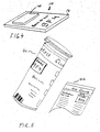
- Figuren 4 und 5 Beispiele für die Aufbringung der sichtbaren Zeichen auf dem Testträger bzw. dessen Verpackung oder Verpackungsbeilage.
- Figure 1 is a block diagram of an evaluation device according to the invention for test carriers
- Figure 2 is a graphical representation of two batch-specific evaluation curves and a standard evaluation curve
- FIG. 3 shows a section of a batch-specific evaluation curve and a standard evaluation curve with the position of the calculation reference point-value pairs modified compared to FIG. 2.
- Figures 4 and 5 examples of the application of the visible characters on the test carrier or its packaging or package insert.
Das Testfeld wird von dem Licht eines Lichtsenders (16) beleuchtet. Das von der Oberfläche des Testfeldes (14) diffus reflektierte Licht wird von einer Meßeinrichtung (18) erfaßt. Die Meßeinrichtung umfaßt üblicherweise einen lichtempfindlichen Empfänger, beispielsweise eine Fotodiode, einen Verstärker und einen Analog-Digital-Wandler. Geeignete Meßeinrichtungen sind bekannt.The test field is illuminated by the light from a light transmitter (16). The light diffusely reflected from the surface of the test field (14) is detected by a measuring device (18). The measuring device usually comprises a light-sensitive receiver, for example a photodiode, an amplifier and an analog-digital converter. Suitable measuring devices are known.
Zentrales Element des Geräts ist ein Prozessor (20) mit zugehörigem, nicht gesondert dargestelltem Speicher. Er dient dazu, die verschiedenen Gerätefunktionen zu steuern und die von der Meßeinrichtung (18) gelieferten physikalischen Meßwerte in die gesuchten Konzentrationswerte umzurechnen. Die so errechneten Werte werden mittels einer Anzeigensteuerung (22) auf einer Anzeige (24) angezeigt. Als Anzeige wird üblicherweise ein digitales Display verwendet.The central element of the device is a processor (20) with associated memory, not shown separately. It is used to control the various device functions and to convert the physical measured values supplied by the measuring device (18) into the concentration values sought. The values calculated in this way are displayed on a display (24) by means of a display control (22). A digital display is usually used as the display.
Um aus den physikalischen Meßwerten die entsprechenden Konzentrationswerte berechnen zu können, benötigt der Prozessor (20) Informationen über die chargenspezifische Auswertekurve. Diese werden ihm im dargestellten Ausführungsbeispiel der Erfindung über drei Tasten (26, 28, 30) eingegeben. Die mit Hilfe der Tasten gewählten Werte werden auf dem Display (24) angezeigt. Wenn die Anzeigen des Displays den beispielsweise auf der Testträgerpackung angegebenen Code richtig wiedergeben, wird dem Prozessor (20) der Befehl gegeben, den auf dem Display angezeigten Code zu übernehmen und abzuspeichern.In order to be able to calculate the corresponding concentration values from the physical measured values, the processor (20) requires information about the batch-specific evaluation curve. These are entered into the illustrated embodiment of the invention using three keys (26, 28, 30). The values selected using the buttons are shown on the display (24). If the displays on the display correctly reflect the code, for example given on the test carrier package, the processor (20) is given the command to accept and save the code shown on the display.
Das Display kann beispielsweise als übliches 7-Segment-Display ausgebildet sein, mit dem neben den zehn Ziffern des Dezimalsystems auch eine Reihe von Zeichen angezeigt werden können. In einer praktisch bevorzugten Ausführungsform kann jede der Stellen des Display 16 verschiedene Zeichen anzeigen, so daß mit Hilfe der Tasten 26 bis 28 für jede Stelle des Codes 16 verschiedene diskrete Werte angezeigt und an den Prozessor (20) übermittelt werden können. Die Zahl 16 ist besonders bevorzugt, weil bis zu 16 verschiedene Werte leicht mit Hilfe eines 4-Bit-Wortes innerhalb des Prozessors codiert und verarbeitet werden können. Je nach den Anforderungen kann aber auch eine andere Anzahl diskreter Einstellwerte zur Anwendung kommen.The display can be designed, for example, as a conventional 7-segment display, which can also be used to display a series of characters in addition to the ten digits of the decimal system. In a practically preferred embodiment, each of the positions on the display can display 16 different characters, so that with the help of the
In Figur 1 erkennt man weiterhin noch einen Timer (32) zur Steuerung des Mikroprozessors und ein Netzteil (34) zur Energieversorgung des Systems. Andere Elemente, wie beispielsweise Elemente zur Kontrolle der Betriebsspannung und dergleichen, sind wie erwähnt der Übersichtlichkeit halber nicht dargestellt.In Figure 1 you can still see a timer (32) for controlling the microprocessor and a power supply (34) for powering the system. Other elements, such as elements for checking the operating voltage and the like, are not shown for the sake of clarity, as mentioned.
Die Erfindung beschäftigt sich nun primär mit einem Verfahren zur Berechnung der Konzentration aus den physikalischen Meßwerten in dem Prozessor (20) mit Hilfe des beispielsweise über die Tasten 26, 28, 30 und das Display (24) eingegebenen aus nur wenigen Stellen mit jeweils einer geringen Anzahl diskreter Werte bestehenden Code. Dieses Verfahren wird im folgenden anhand der Figuren 2 und 3 näher erläutert. In Figur 2 sind drei Kurven S, I und J eingezeichnet. Die gestrichelte Kurve I zeigt den Verlauf einer beispielhaften Auswertekurve für einen optischen Test zur Bestimmung der Glucose im Blut. Auf der Ordinate ist das diffuse Reflektionsvermögen R bei einer bestimmten durch das optische System des Geräts festgelegten Meßwellenlänge aufgetragen. Auf der Abszissenachse ist die entsprechende Konzentration des zu bestimmenden Parameters, hier also der Glucose, aufgetragen. Man erkennt bei der Kurve I, daß aufgrund der charakteristischen Eigenschaften der Testfelder des analytischen Testträgers das diffuse Reflexionsvermögen R bei niedrigen Konzentrationswerten hoch ist. Im mittleren Konzentrationsbereich nimmt es mit einer von rechts oben gesehen konvexen Krümmung zunehmend ab. Der Kurvenverlauf geht dann nach Durchlaufen eines Wendepunktes in eine konkave Krümmung über. Das diffuse Reflexionsvermögen R sinkt in diesem Bereich mit zunehmender Konzentration C weniger stark und verändert sich schließlich bei hohen Konzentrationen nur noch wenig.The invention is now primarily concerned with a method for calculating the concentration from the physical measured values in the processor (20) with the aid of, for example, the
Der allgemeine Verlauf von Auswertekurven von Testträgern ist von den gewählten Reagenzien und sonstigen Eigenschaften der Testträger abhängig und daher von Test zu Test verschieden. Ein Verlauf der hier dargestellten Art ist jedoch für viele Fälle typisch. Er hat den Vorteil, daß im mittleren Bereich eine hohe Abhängigkeit der Remission von der Konzentration gegeben ist. Dies ist günstig für eine hohe Meßgenauigkeit.The general course of evaluation curves of test carriers depends on the selected reagents and other properties of the test carriers and therefore differs from test to test. However, a course of the type shown here is typical for many cases. It has the advantage that there is a high dependence of the remission on the concentration in the middle region. This is favorable for high measuring accuracy.
Wie erwähnt, sind die Auswertekurven für verschiedene Testträger einer Herstellungscharge nicht gleich. Beispielhaft ist in Figur 2 eine weitere Auswertekurve strichpunktiert eingezeichnet, die mit J bezeichnet ist. Man erkennt, daß diese Kurve erheblich verschieden ist von der Auswertekurve I. Sie stimmt jedoch in einigen grundsätzlichen Eigenschaften mit dieser überein. Insbesondere hat auch sie einen zunächst konkaven und dann nach einem Wendepunkt einen konvexen Verlauf. Weitere Auswertekurven sind der Übersichtlichkeit halber nicht dargestellt. Es sei jedoch betont, daß jede Charge eine andere Auswertekurve hat, so daß es eine unendlich große Vielzahl von möglichen Auswertekurven gibt, die im Rahmen der Erfindung in guter Näherung berücksichtigt werden können.As mentioned, the evaluation curves for different test carriers of a production batch are not the same. As an example, a further evaluation curve, which is designated by J, is shown in dash-dot lines in FIG. It can be seen that this curve is considerably different from the evaluation curve I. However, it agrees with this in some basic properties. In particular, it too has an initially concave course and then a convex course after a turning point. For the sake of clarity, further evaluation curves are not shown. However, it should be emphasized that each batch has a different evaluation curve, so that there are an infinitely large number of possible evaluation curves which can be taken into account in a good approximation within the scope of the invention.
Wesentlich für die vorliegende Erfindung ist nun, daß eine Standardauswertekurve festgelegt und in dem Speicher des Auswertegeräts abgespeichert wird, deren Verlauf dem der Auswertekurven in dem im folgenden definierten Sinne ähnlich ist. Eine derartige Standardauswertekurve ist in Figur 2 durchgezogen eingezeichnet und mit S bezeichnet.It is essential for the present invention that a standard evaluation curve is defined and stored in the memory of the evaluation device, the course of which is similar to that of the evaluation curves in the sense defined below. Such a standard evaluation curve is drawn through in FIG. 2 and labeled S.
Die Standardauswertekurve soll zunächst im Wertebereich der Auswertekurven verlaufen. Damit ist gemeint, daß die Standardauswertekurve zumindest in dem gewünschten Konzentrationsbereich innerhalb der Extremwerte des physikalischen Meßwertes der in der Praxis vorkommenden Auswertekurven der Testträger liegt. Wie in Figur 2 dargestellt ist, werden diese Extremwerte nicht etwa durchgängig von den gleichen Auswertekurven markiert. In der dargestellten Ausführungsform hat die Kurve I zum Beispiel im Bereich niedriger und hoher Konzentrationen besonders hohe R-Werte und die Kurve J besonders niedrige R-Werte. Im Bereich mittlerer Konzentrationen ist es gerade umgekehrt. Die Standardauswertekurve S soll irgendwie im Bereich der Auswertekurven liegen. In vielen Fällen ist es besonders günstig, wenn sie etwa im mittleren Wertebereich der Auswertekurven, also etwa im Zentrum der durch eine Vielzahl von Vorversuchen ermittelten Auswertekurven verschiedener Testträgerchargen verläuft.The standard evaluation curve should initially run in the value range of the evaluation curves. This means that the standard evaluation curve lies at least in the desired concentration range within the extreme values of the physical measured value of the evaluation curves of the test carriers that occur in practice. As shown in FIG. 2, these extreme values are not marked approximately consistently by the same evaluation curves. In the illustrated embodiment, for example, curve I has particularly high R values in the range of low and high concentrations and curve J has particularly low R values. In the range of medium concentrations it is just the opposite. The standard evaluation curve S should somehow be in the range of the evaluation curves. In many cases it is particularly favorable if it runs approximately in the middle value range of the evaluation curves, that is to say approximately in the center of the evaluation curves of various test carrier batches determined by a large number of preliminary tests.
Weiter soll die Standardauswertekurve eine konvexe bzw. konkave Krümmung im wesentlichen in den gleichen Abschnitten von Werten des diffusen Reflexionsvermögens aufweisen wie die Auswertekurven. Quantitativ läßt sich sagen, daß der Wendepunkt zwischen einem konkav und einem konvex gekrümmten Bereich der Standardkurve bei einem solchen Wert des diffusen Reflexionsvermögens liegen sollte, daß die den Wendepunkten der möglichen Auswertekurven der Testträgerchargen entsprechenden Werte des diffusen Reflexionsvermögens sich um höchstens 20 %, bevorzugt höchstens 10 % von diesem unterscheiden.Furthermore, the standard evaluation curve should have a convex or concave curvature essentially in the same sections of values of the diffuse reflectivity as the evaluation curves. It can be said quantitatively that the point of inflection between a concave and a convexly curved region of the standard curve should lie at such a value of the diffuse reflectivity that the values of the diffuse reflectance corresponding to the inflection points of the possible evaluation curves of the test carrier batches are at most 20%, preferably at most Distinguish 10% from this.
Wie aus Figur 2 zu erkennen ist, stimmen die Konzentrationsbereiche, in denen die Kurven I und J die gleiche Krümmung aufweisen, nicht gut überein. Insbesondere liegt der Wendepunkt nicht beim gleichen Konzentrationswert. Es ist deshalb nicht möglich und auch nicht notwendig, daß die Standardauswertekurve in den genau gleichen Abschnitten von Konzentrationswerten die gleiche Krümmung aufweist wie die Auswertekurven. Es genügt, wenn diese weitgehend übereinstimmen, so daß in dem weiter unten näher beschriebenen Iterationsverfahren ausreichend exakte Werte des Meßergebnisses erreicht werden.As can be seen from Figure 2, the concentration ranges in which the curves I and J have the same curvature do not match well. In particular, the turning point is not at the same concentration value. It is therefore not possible and also not necessary for the standard evaluation curve to have the same curvature as the evaluation curves in the exact same sections of concentration values. It is sufficient if these largely agree, so that sufficiently precise values of the measurement result are achieved in the iteration method described in more detail below.
Die Standardkurve kann z. B. in Form eines Polynoms ausgedrückt werden, dessen Koeffizienten abgespeichert werden. Bevorzugt wird sie als Polygon dargestellt, d. h. es werden Punkte, die auf dem Kurvenverlauf liegen, abgespeichert und zwischen den Punkten wird linear interpoliert. Selbstverständlich kann die Standardkurve auch in einer transformierten Form (z. B. linear transformiert) abgespeichert werden. In diesem Fall muß die Transformation bei den folgenden Berechnungen berücksichtigt werden.The standard curve can e.g. B. can be expressed in the form of a polynomial, the coefficients of which are stored. It is preferably represented as a polygon, i. H. Points lying on the curve are saved and linear interpolation between the points. Of course, the standard curve can also be saved in a transformed form (e.g. linearly transformed). In this case, the transformation must be taken into account in the following calculations.
Weiter ist für die Erfindung wesentlich, daß auf der Standardkurve in der Nähe jedes Wendepunktes zwischen einem konkav und einem konvex gekrümmten Abschnitt ein Punkt definiert und im Speicher abgespeichert ist, der als Standardstützpunkt bezeichnet wird. Er ist in Figur 2 mit Rsb, Csb bezeichnet. Der Begriff "in der Nähe" ist hier analog zu dem Begriff "im wesentlichen" im vorhergehenden Absatz zu verstehen, d. h. der Konzentrationswert des Standardstützpunktes darf sich nicht so sehr vom Konzentrationswert des Wendepunktes unterscheiden, daß das Verfahren zur Berechnung der Konzentration aus den Meßwerten insgesamt zu unbefriedigenden Ergebnissen führt. Wie groß diese Abweichung im Einzelfall sein kann, läßt sich im Einzelfall aufgrund der erfindungsgemäßen Lehre leicht bestimmen. Quantitativ läßt sich sagen, daß der Konzentrationswert des Standardstützpunktes um nicht mehr als 20 %, bevorzugt um nicht mehr als 10 % vom Konzentrationswert des Wendepunktes abweichen sollte.It is also essential for the invention that a point is defined on the standard curve in the vicinity of each turning point between a concave and a convexly curved section and is stored in the memory, which is referred to as the standard base. It is designated R sb , C sb in FIG. The term "near" is to be understood here analogously to the term "essentially" in the previous paragraph, ie the concentration value of the standard base must not differ so much from the concentration value of the turning point that the method for calculating the concentration from the measured values leads to unsatisfactory results overall. How large this deviation can be in individual cases can easily be determined in individual cases on the basis of the teaching according to the invention. It can be said quantitatively that the concentration value of the standard base should not deviate from the concentration value of the turning point by more than 20%, preferably by not more than 10%.
Weitere Standardstützpunkte befinden sich in der Nähe der Enden des zu bestimmenden Konzentrationsbereiches. Entscheidend ist hier der im praktischen Einsatz tatsächlich benutzte Wertebereich von Konzentrationswerten, nicht der möglicherweise darüberhinaus gehende, zwar technisch mögliche, aber in der Praxis bei dem bestimmten analytischen System nicht benutzte Wertebereich. Der Begriff "in der Nähe" ist analog wie im vorhergehenden Absatz zu verstehen.Further standard bases are located near the ends of the concentration range to be determined. What is decisive here is the range of values of concentration values actually used in practical use, not the range of values that may go beyond this, although it is technically possible but is not used in practice in the particular analytical system. The term "near" is to be understood in the same way as in the previous paragraph.
Ein wesentliches Merkmal der Erfindung ist weiterhin, daß dem Gerät die chargenspezifischen Auswertekurven nicht in Form einer beispielsweise binär codierten mathematischen Funktion übermittelt werden, die jedem Wert des diffusen Reflektionsvermögens einen Konzentrationswert zuordnen, sondern daß lediglich eine beschränkte Anzahl von diskreten Wertepaaren Ria, Cia; Rib, Cib; Ric, Cic; ... aus einem endlichen Vorrat fest programmierter Berechnungsstützpunkte übermittelt wird. Die Berechnungsstützpunkte sind also im vorhinein unabhängig von der Auswertekurve festgelegt und im Speicher des Auswertegerätes abgespeichert. Je ein Satz von Berechnungsstützpunkten befindet sich jeweils in der Umgebung der Standardstützpunkte. Normalerweise wird in der Umgebung jedes Standardstützpunktes eine gleiche Anzahl Berechnungsstützpunkte definiert, d. h. jeder Satz hat die gleiche Zahl von Punkten. Bei einem Kurvenverlauf der in Figur 2 dargestellten Art mit einem Standardstützpunkt in der Nähe des einzigen Wendepunktes und zwei weiteren Standardstützpunkten in der Nähe der Enden des zu bestimmenden Konzentrationsbereiches, also insgesamt drei Standardstützpunkten, werden also drei gleich große Sätze von Berechnungsstützpunkten definiert. Jeder dieser Sätze kann vorteilhafterweise 16 verschiedene Berechnungsstützpunkte (d. h. die diese Berechnungsstützpunkte definierenden Wertepaare Ria, Cia; Rib, Cib; Ric, Cic; mit jeweils i = 1...16) enthalten. Diese im Gerät programmierten Wertepaare werden dann in der im Zusammenhang mit Figur 1 beschriebenen Art und Weise, beispielsweise mit Hilfe der Tasten 26, 28, 30 in Anpassung auf die jeweilige Teststreifencharge angewählt. Jedes der 16 mit den Tasten 26, 28, 30 anwählbaren Zeichen entspricht einem Wertepaar. So dient beispielsweise die erste Ziffer der Anwahl von einem der 16 Berechnungsstützpunkte Ria, Cia, die zweite Ziffer der Anwahl von einem der 16 Berechnungsstützpunkte Rib, Cib und die dritte Ziffer der Anwahl von einem der 16 Berechnungsstützpunkte Ric, Cic. Für jede Testträgercharge erhält der Benutzer des Auswertegerätes eine Anweisung, beispielsweise in Form eines Aufdrucks auf der Verpackung, welche Zeichenfolge er zur Anwahl der Berechnungsstützpunkte auswählen soll. Durch das Eintasten dieser Zeichenfolge wird für jeden Satz von Berechnungsstützpunkten jeweils ein Wertepaar angewählt.An essential feature of the invention is that the batch-specific evaluation curves are not transmitted to the device in the form of a binary-coded mathematical function, for example, which assign a concentration value to each value of the diffuse reflectivity, but rather that only a limited number of discrete pairs of values R ia , C ia ; R ib , C ib ; R ic , C ic ; ... is transmitted from a finite supply of permanently programmed calculation bases. The calculation support points are therefore defined in advance independently of the evaluation curve and are stored in the memory of the evaluation device. A set of calculation bases is located in the vicinity of the standard bases. Usually, an equal number of calculation bases is defined in the vicinity of each standard base, ie each set has the same number of points. In the case of a curve of the type shown in FIG. 2 with a standard base near the single turning point and two further standard bases near the ends of the concentration range to be determined, i.e. a total of three standard bases, three sets of calculation bases of the same size are defined. Each of these sentences can advantageously 16 different calculation bases (ie the value pairs defining these calculation bases R ia , C ia ; R ib , C ib ; R ic , C ic ; each with i = 1 ... 16). These pairs of values programmed in the device are then selected in the manner described in connection with FIG. 1, for example with the aid of the
Das erfindungsgemäße Verfahren ist besonders vorteilhaft, wenn die Zahl der zur Auswahl der Wertepaare einzustellenden und zu übermittelnden Informationen klein gehalten wird. Deswegen ist die Zahl der Berechnungsstützpunktsätze, die den Standardstützpunkten auf der Standardkurve zugeordnet werden, auf höchstens zehn, bevorzugt höchstens fünf beschränkt. Für jede Testträgercharge werden somit nur wenige Wertepaare von Berechnungsstützpunkten an den Prozessor übermittelt. Die Zahl der Berechnungsstützpunkte pro Satz beträgt bevorzugt höchstens 256.The method according to the invention is particularly advantageous if the number of information items to be set and transmitted to select the value pairs is kept small. For this reason, the number of calculation base sets that are assigned to the standard base points on the standard curve is limited to at most ten, preferably at most five. For each test carrier batch, only a few pairs of values from calculation bases are thus transmitted to the processor. The number of calculation support points per set is preferably at most 256.
Wie erwähnt, liegen die Sätze von Berechnungsstützpunkten in der Umgebung der Standardstützpunkte. Die genauere Lage ergibt sich aus dem weiter unten beschriebenen Iterationsverfahren und kann vom Fachmann aufgrund der erfindungsgemäßen Lehre leicht festgelegt werden.As mentioned, the sets of calculation bases are in the vicinity of the standard bases. The more precise location results from the iteration process described below and can easily be determined by a person skilled in the art on the basis of the teaching according to the invention.
Bevorzugt liegen die Berechnungsstützpunkte jeweils auf einer die Standardkurve in einem stumpfen Winkel schneidenden Linie. In Figur 2 sind drei derartige Linien a, b und c eingezeichnet. Sie sind den Standardstützpunkten Rsa, Csa; Rsb, Csb und Rsc, Csc zugeordnet. In der dargestellten, bevorzugten Ausführungsform schneiden sie die Standardkurve in diesen Punkten. Sie sind bevorzugt, wie dargestellt, näherungsweise gerade ausgebildet.The calculation reference points preferably lie on a line intersecting the standard curve at an obtuse angle. In Figure 2 three such lines a, b and c are drawn. They are the standard bases R sa , C sa ; R sb , C sb and R sc , C sc assigned. In the preferred embodiment shown, they intersect the standard curve at these points. As shown, they are preferably approximately straight.
Figur 3 zeigt nur je einen Teil einer Standardkurve S und einer Auswertekurve I, und zwar den zwischen zwei Standardstützpunkten Rsa, Csa; Rsb, Csb bzw. zwei Berechnungsstützpunkten Ria, Cia; Rib, Cib liegenden Teil. Bei der hier dargestellten besonders einfachen Ausführungsform der Erfindung liegen die Berechnungsstützpunkte jeweils auf Geraden, die parallel zu einer Koordinate des Koordinatensystems verlaufen. In die Zeichnung sind jeweils zehn den Standardstützpunkten Rsa, Csa und Rsb, Csb zugeordnete Berechnungsstützpunkte eingezeichnet. Die dem Standardstützpunkt Rsa, Csa zugeordneten Berechnungsstützpunkte R₁a, C₁a;...; R₁₀a, C₁₀a liegen auf der Geraden a, welche parallel zur Ordinate des Koordinatensystems verläuft. Infolgedessen haben alle diese Berechnungsstützpunkte den gleichen Konzentrationswert wie der entsprechende Standardstützpunkt (C₁a = C₂a = ... = C₁₀a = Csa). Dies vereinfacht die Abspeicherung im Gerät, weil für jeden Berechnungsstützpunkt und den Standardstützpunkt nur jeweils der R-Wert getrennt abgespeichert werden muß, während der C-Wert, der für alle Berechnungsstützpunkt und den Standardstützpunkt gleich ist, nur einmal abgespeichert wird. Entsprechendes gilt für die auf der zur Abszisse parallelen Geraden b liegenden Berechnungsstützpunkte R₁b, C₁b;...;R₁₀b, C₁₀b. Hier ist der R-Wert für alle Berechnungsstützpunkte gleich und stimmt mit dem R-Wert des zugehörigen Standardstützpunktes Rsb überein.FIG. 3 shows only part of a standard curve S and one evaluation curve I, namely that between two standard reference points R sa , C sa ; R sb , C sb or two calculation bases R ia , C ia ; R ib , C ib lying part. In the particularly simple embodiment of the invention shown here, the calculation reference points each lie on straight lines that run parallel to a coordinate of the coordinate system. The drawing shows ten calculation bases assigned to the standard bases R sa , C sa and R sb , C sb . The calculation bases R₁ a , C₁ a assigned to the standard base R sa , C sa ; ...; R₁₀ a , C₁₀ a lie on the straight line a, which runs parallel to the ordinate of the coordinate system. As a result, all of these calculation bases have the same concentration value as the corresponding standard base (C₁ a = C₂ a = ... = C₁₀ a = C sa ). This simplifies the storage in the device because only the R-value has to be saved separately for each calculation base and the standard base, while the C-value, which is the same for all calculation base and the standard base, is only stored once. The same applies to the calculation bases lying on the straight line b parallel to the abscissa R₁ b , C₁ b ; ...; R₁₀ b , C₁₀ b . Here, the R value is the same for all calculation bases and corresponds to the R value of the associated standard base R sb .
Das Verfahren zur Berechnung eines Konzentrationswertes Cix aus einem gemessenen Wert der diffusen Reflektion Rix wird im folgenden ebenfalls anhand der Figur 3 erläutert.The method for calculating a concentration value C ix from a measured value of the diffuse reflection R ix is also explained below with reference to FIG. 3.
Gemessen wird beispielsweise ein diffuses Reflektionsvermögen des Wertes Rix. Die wahre Auswertekurve des verwendeten Testträgers ist in Figur 3 gestrichelt dargestellt und mit I bezeichnet. Die durch den Meßwert Rix definierte Horizontale schneidet die Kurve I im Punkt P, der diesem Punkt P zugeordnete Konzentrationswert ist also der wahre Konzentrationswert, der bestimmt werden soll. Ihn exakt zu bestimmen, ist aber nur möglich, wenn die Kurve I für jede Charge im Auswertegerät vollständig abgespeichert ist. Da die Auswertekurven von analytischen Testträgern sich auch mit sehr komplizierten Funktionen höherer Ordnung nicht exakt darstellen lassen, ist dies grundsätzlich nicht möglich. Es wird daher mit Näherungsverfahren gearbeitet, mit Hilfe deren die Auswertekurven näherungsweise dargestellt werden, d. h. jedem Meßwert Rix ein Konzentrationswert Cix zugeordnet wird, der in möglichst guter Näherung der wahren Auswertekurve entspricht. Dies ist grundsätzlich möglich, indem man die jeweilige Auswertekurve der Testträgercharge in der weiter oben bereits angesprochenen Weise in Form einer Funktion höherer Ordnung darstellt und die Parameter dieser Funktion an das Auswertegerät übermittelt. Dies erfordert jedoch einen sehr großen Aufwand, insbesondere bezüglich des Auswertegerätes, wie ebenfalls weiter oben näher erläutert wurde.For example, a diffuse reflectivity of the value R ix is measured. The true evaluation curve of the test carrier used is shown in dashed lines in FIG. 3 and labeled I. The horizontal defined by the measured value R ix intersects the curve I at point P, so the concentration value assigned to this point P is the true concentration value that is to be determined. However, it can only be determined exactly if curve I is completely stored in the evaluation unit for each batch. Since the evaluation curves of analytical test carriers cannot be represented exactly even with very complicated functions of a higher order, this is fundamentally not possible. Approximation methods are therefore used, with the aid of which the evaluation curves are approximately represented, ie each measurement value R ix is assigned a concentration value C ix which corresponds as closely as possible to the true evaluation curve. In principle, this is possible by representing the respective evaluation curve of the test carrier batch in the manner already mentioned above in the form of a function of a higher order and transmitting the parameters of this function to the evaluation device. However, this requires a great deal of effort, in particular with regard to the evaluation device, as was also explained in more detail above.
Für einfachere Auswertegeräte wird deswegen in der Regel eine einzige mittlere Auswertekurve für alle Testträgerchargen herangezogen. Nimmt man in Figur 3 an, daß die dort eingezeichnete Standardkurve S eine solche mittlere Auswertekurve ist, so sieht man, daß die dem Meßwert Rix entsprechende Horizontale diese Kurve in dem Punkt Q schneidet. Man erkennt sofort, daß der diesem Punkt Q entsprechende Konzentrationswert von dem wahren Konzentrationswert sehr weit abweicht. Eine derartig grobe Annäherung ist deshalb vollkommen unbefriedigend.For simpler evaluation devices, therefore, a single average evaluation curve is generally used for all test carrier batches. If it is assumed in FIG. 3 that the standard curve S drawn there is such a middle evaluation curve, it can be seen that the horizontal line corresponding to the measured value R ix intersects this curve at point Q. It can be seen immediately that the concentration value corresponding to this point Q deviates very far from the true concentration value. Such a rough approximation is therefore completely unsatisfactory.
Die vorliegende Erfindung erreicht nun mit einem außerordentlich geringen Aufwand eine sehr viel bessere Annäherung an die wahre Auswertekurve, indem aus dem Meßwert Rix zunächst ein Standardmeßwert Rsx auf der Standardkurve S und dann aus dem dem Standardmeßwert Rsx entsprechenden Konzentrationswert Csx der gesuchte Konzentrationswert Cix berechnet wird. Für den ersten Berechnungsschritt wird einerseits der Abstand der beiden R-Werte, der dem Meßwert Rix nächstliegenden Berechnungsstützpunkte (z. B. Ria-Rib) und andererseits der Abstand der beiden R-Werte der Standardstützpunkte (z. B. Rsa-Rsb), denen diese Berechnungsstützpunkte zugeordnet sind, verwendet. Die Erfindung basiert dabei wesentlich auf der Erkenntnis, daß bei entsprechender Wahl der Berechnungsstützpunkte und der Standardstützpunkte sowie einem im angesprochenen Sinne ähnlichen Kurvenverlauf der Standardkurve zu den Auswertekurven die relative Veränderung eines Remissionswertes gegenüber den benachbarten Berechnungsstützpunktwerten in überraschend guter Näherung ähnlich verläuft, wie die entsprechende Änderung auf der Standardkurve im Vergleich zu den Standardstützpunkten.The present invention is now achieved with a very small effort a much better approximation to the true evaluation curve by ix from the measured value R first a Standardmeßwert R sx on the standard curve south and then from the Standardmeßwert R sx corresponding concentration value C sx the sought concentration value C ix is calculated. For the first calculation step on the one hand the distance between the two R values, the calculation reference points closest to the measured value R ix (e.g. R ia -R ib ) and on the other hand the distance between the two R values of the standard reference points (e.g. R sa -R sb ) to which these calculation bases are assigned. The invention is essentially based on the knowledge that with a suitable choice of the calculation reference points and the standard reference points as well as a curve course of the standard curve similar to the evaluation curves, the relative change of a remission value compared to the neighboring calculation reference point values is surprisingly similar to the corresponding change on the standard curve compared to the standard bases.
Dies läßt sich anhand von Figur 3 näher erläutern, wobei die besonders bevorzugte, aber nicht einzig mögliche lineare Näherung beschrieben wird. Dabei ist die Vorzeichenkonvention des angeführten Berechnungsbeispiels so gewählt, daß sich in dem dargestellten Kurvenabschnitt positive Remissionswerte und Konzentrationswerte ergeben. Für anders geartetee Kurvenabschnitte können die Vorzeichen entsprechend abgewandelt werden.This can be explained in more detail with reference to FIG. 3, the particularly preferred but not the only possible linear approximation being described. The sign convention of the calculation example given is chosen so that positive remission values and concentration values result in the curve section shown. The sign can be modified accordingly for other curve sections.
Zur Berechnung des Standardmeßwertes Rsx auf der Standardkurve wird zunächst das Verhältnis α aus dem Abstand des Meßwertes Rix von dem benachbarten Berechnungsstützpunkt Ria zu dem Abstand der Berechnungsstützpunkte Ria und Rib gebildet. Dieses Verhältnis wird mit dem Abstand der Standardstützpunkte Rsa und Rsb multipliziert und der so erhaltene relative Remissionsabfall gegenüber dem Standardstützpunkt Rsa wird von diesem subtrahiert. Das Ergebnis ist der Standardmeßwert Rsx, der den dem gemessenen diffusen Reflektionsvermögen Rix im Sinne der vorliegenden Erfindung entsprechenden Wert auf der Standardkurve darstellt.
Dieser Wert Rsx entspricht einem Konzentrationswert Csx auf der Standardkurve S. Dieser Wert wird nun in einem entsprechenden Näherungsverfahren unter Berücksichtigung einerseits des Abstandes der Konzentrationswerte Cia, Cib der benachbarten Berechnungsstützpunkte und andererseits der Konzentrationswerte der benachbarten Standardstützpunkte Csa, Csb umgerechnet. In linearer Näherung wird die Relation zwischen dem Abstand des Wertes Csx von dem benachbarten Standardkonzentrationswert Csa zu dem Abstand zwischen den Standardkonzentrationswerten Csa und Csb gebildet. Dieses Berhältnis β wird mit dem Abstand der beiden Konzentrationswerte der Verechnungsstützpunkte Cib und Cia multipliziert und zu dem Konzentrationswert Cia des benachbarten Berechnungsstützpunktes addiert.
Auf diese Weise wird der Konzentrationswert Cix erhalten. Dieser entspricht nicht exakt, aber in sehr guter Näherung dem zu messenden Konzentrationswert. Dies wird in Figur 3 dadurch verdeutlicht, daß der Punkt Cix, Rix von dem auf der wahren Auswertekurve liegende Punkt P geringfügig abweicht.In this way, the concentration value C ix is obtained. This does not correspond exactly, but in a very good approximation to the concentration value to be measured. This is illustrated in FIG. 3 in that the point C ix , R ix deviates slightly from the point P lying on the true evaluation curve.
Wie erwähnt, kann statt der im einzelnen beschriebenen linearen Näherung auch ein anderes Näherungsverfahren gewählt werden, bei dem die Relation der erwähnten Abstände zwischen des Berechnungsstützpunkten einerseits und den Standardstützpunkten andererseits berücksichtigt wird. In besonderen Fällen kann sich beispielsweise eine logarithmische oder quadratische Näherung empfehlen. Die beschriebene lineare Näherung ist jedoch besonders einfach und führt zu sehr befriedigenden praktischen Ergebnissen.As mentioned, instead of the linear approximation described in detail, another approximation method can also be selected, in which the relation of the mentioned distances between the calculation reference points on the one hand and the standard reference points on the other hand is taken into account. In special cases, a logarithmic or quadratic approximation can be recommended. However, the linear approximation described is particularly simple and leads to very satisfactory practical results.
Die Qualität der Näherung gemäß dem erfindungsgemäßen Verfahren ist sehr wesentlich von der Wahl der Standardkurve, der Standardstützpunkte und der Berechnungsstützpunkte innerhalb der im einzelnen dargelegten und beanspruchten Grenzen abhängig. Zur Optimierung empfiehlt sich ein Iterationsverfahren, das etwa wie folgt abläuft:The quality of the approximation according to the method according to the invention is very much dependent on the choice of the standard curve, the standard reference points and the calculation reference points within the limits set out and claimed in detail. For optimization purposes, an iteration process is recommended, which proceeds as follows:
Zunächst wird eine Vielzahl von Testträgerchargen hergestellt und die zugehörigen Auswertekurven werden exakt vermessen. Danach wird eine erste Standardkurve so gelegt, daß sie etwa in der Mitte der Auswertekurven verläuft. Die Standardstützpunkte werden zunächst genau auf die Wendepunkte der Standardkurve und auf die Enden des Meßbereichs gelegt. Durch die Standardstützpunkte werden gerade oder nur leicht gekrümmte in einem stumpfen Winkel zum Verlauf der Standardkurve in dem jeweiligen Standardstützpunkt verlaufende Kurven gelegt. Bevorzugt sollte man der Einfachheit halber zunächst Geraden versuchen, die parallel zu den Achsen des Koordinatensystems verlaufen. Auf diesen werden Berechnungsstützpunkte definiert, die gleiche Abstände voneinander haben. Die Abstände und die Verteilung der Berechnungsstützpunkte auf beiden Seiten des Standardstützpunktes werden dabei so gewählt, daß die äußersten Berechnungsstützpunkte noch außerhalb der äußersten Auswertekurven der untersuchten Testträgerchargen liegen.First of all, a large number of test carrier batches are produced and the associated evaluation curves are measured precisely. Then a first standard curve is laid so that it runs approximately in the middle of the evaluation curves. The standard reference points are first placed exactly on the turning points of the standard curve and on the ends of the measuring range. The standard bases are used to lay straight or only slightly curved curves at an obtuse angle to the course of the standard curve in the respective standard base. For the sake of simplicity, one should preferably first try straight lines that run parallel to the axes of the coordinate system. This is used to define calculation bases that are equidistant from each other. The distances and the distribution of the calculation bases on both sides of the standard base are chosen so that the outermost calculation bases are still outside the outermost evaluation curves of the test carrier batches examined.
Für jede Testträgercharge werden nun zunächst diejenigen Berechnungsstützpunkte aus jedem Satz von Berechnungsstützpunkten gewählt, die möglichst nahe bei dem Kurvenverlauf liegen. Mit Hilfe dieser Berechnungsstützpunkte und des erfindungsgemäßen Verfahrens wird der angenäherte Verlauf der Auswertekurve berechnet, graphisch dargestellt und mit der jeweiligen tatsächlichen Auswertekurve verglichen. Werden alle zuvor vermessenen Auswertekurven mit der gewünschten Qualität der Näherung richtig dargestellt, so ist das Verfahren beendet. Im Regelfall werden aber zumindest einige Auswertekurven, zumindest in Teilbereichen, nicht mit der notwendigen Qualität wiedergegeben. In derartigen Fällen wird der Verlauf der Standardkurve und/oder die Wahl der Standardstützpunkte und der Berechnungsstützpunkte verändert und ein neuer Probelauf durchgeführt, um zu prüfen, ob nunmehr die notwendige Genauigkeit erreicht ist. Dieses Verfahren erscheint mühsam, kann jedoch mit modernen Datenverarbeitungseinrichtungen verhältnismäßig schnell routinemäßig durchgeführt werden. Entscheidend ist, daß aufgrund der grundlegenden in den Ansprüchen definierten Lehren der vorliegenden Erfindung auch sehr kompliziert gestaltete Auswertekurven mit einem äußerst geringen Aufwand seitens des Auswertegerätes und mit sehr guter Genauigkeit berechnet werden können, d. h. daß das letztlich möglich ist, chargenspezifische Abweichungen der Testträger untereinander in einem verhältnismäßig einfach aufgebauten und kostengünstigen Gerät zu berücksichtigen, wobei zugleich das System aus Gerät und Testträger besonders einfach zu handhaben ist.For each test carrier batch, those calculation bases that are as close as possible to the course of the curve are selected from each set of calculation bases. With the aid of these calculation reference points and the method according to the invention, the approximate course of the evaluation curve is calculated, graphically represented and compared with the respective actual evaluation curve. If all previously measured evaluation curves are correctly displayed with the desired quality of approximation, the process is ended. As a rule, however, at least some evaluation curves, at least in some areas, are not reproduced with the necessary quality. In such cases, the course of the standard curve and / or the selection of the standard reference points and the calculation reference points is changed and a new test run is carried out in order to check whether the necessary accuracy has now been achieved. This method appears tedious, but can be carried out relatively quickly routinely with modern data processing devices. It is crucial that, based on the basic teachings of the present invention defined in the claims, even very complicated evaluation curves can be calculated with very little effort on the part of the evaluation device and with very good accuracy can, ie that it is ultimately possible to take account of batch-specific deviations of the test carriers from one another in a relatively simply constructed and inexpensive device, the system of device and test carrier being particularly easy to handle at the same time.
Die Erfindung kann vorteilhaft auch für Auswertegeräte eingesetzt werden, bei denen mehrere verschiedene Typen von Testträgern vermessen werden können, d. h. mit denen die Bestimmung mehrerer verschiedener Parameter möglich ist. In diesem Fall können für jeden Testträgertyp getrennt die Standardkurve, die Standardstützpunkte und die Berechnungsstützpunkte abgespeichert werden. Je nach dem Kurvenverlauf ist es jedoch auch möglich, daß die gleichen Berechnungsstützpunkte oder Standardstützpunkte und unter Umständen auch Teile des Verlaufs der Standardkurven für mehrere Testträgertypen gemeinsam benutzt werden. Dadurch wird Speicherkapazität gespart. Selbstverständlich muß für jede Testträgercharge eines bestimmten Testträgertyps die jeweilige zugeordnete Kombination der Berechnungsstützpunkte getrennt angewählt werden. Wenn beispielsweise für jeden Testträgertyp drei Sätze von Berechnungsstützpunkten zur Verfügung stehen, kann die Anwahl zweckmäßigerweise durch eine Folge von vier Zeichen erfolgen. Das erste Zeichen charakterisiert dann den Testträgertyp. Die weiteren drei Zeichen charakterisieren die Auswahl der Berechnungsstützpunkte aus dem endlichen Vorrat der für den jeweiligen Testträgertyp abgespeicherten Berechnungsstützpunkte.The invention can advantageously also be used for evaluation devices in which several different types of test carriers can be measured, i. H. with which the determination of several different parameters is possible. In this case, the standard curve, the standard reference points and the calculation reference points can be saved separately for each test carrier type. Depending on the course of the curve, however, it is also possible that the same calculation points or standard points and, under certain circumstances, also parts of the course of the standard curves are used together for several types of test carriers. This saves storage capacity. Of course, the respective assigned combination of calculation bases must be selected separately for each test carrier batch of a specific test carrier type. If, for example, three sets of calculation bases are available for each test carrier type, the selection can expediently be made by a sequence of four characters. The first character then characterizes the test carrier type. The other three characters characterize the selection of the calculation bases from the finite supply of the calculation bases stored for the respective test carrier type.
Fig. 4 zeigt beispielhaft, wie die sichtbaren Zeichen, aufgrund deren die Berechnungsstützpunkte ausgewählt werden, auf einem Testträger 10 angebracht sind. In diesem Fall sind es die alphanumerischen Zeichen "9F4", aufgrund deren drei Berechnungsstützpunkte aus einem Satz von jeweils 16 Berechnungsstützpunkten ausgewählt werden. Sie sind auf der Basis 12 des Testträgers 10 aufgebracht. Alle Testträger einer Herstellungscharge haben die gleichen sichtbaren Zeichen.4 shows an example of how the visible characters, on the basis of which the calculation bases are selected, are attached to a
Fig. 5 zeigt ein Beispiel, bei dem die sichtbaren Zeichen auf einer Testträgerverpackung 40 und/oder einer entsprechenden Packungsbeilage 42 aufgebracht sind. Bei diesem Verfahren wird die Herstellung vereinfacht, weil nicht jeder Testträger mit dem sichtbaren Zeichen bedruckt werden muß.5 shows an example in which the visible characters are applied to a
Claims (9)
(1) einen Testträger (10) mit einem Testfeld (14), welches ein Reagenz enthält, das nach Aufbringen der Probenflüssigkeit mit dem Bestandteil reagiert, wobei sich eine meßbare physikalische Größe, insbesondere das diffuse Reflexionsvermögen des Testfeldes (14) in Abhängigkeit der Konzentration (C) des Bestandteils der Körperflüssigkeit ändert und
(2) ein Gerät mit einer Meßeinrichtung (18) zur Messung der physikalischen Größe und einer einen Speicher und einen Prozessor (20) einschließenden Auswerteelektronik zur Messung des Meßwerts (R) der physikalischen Größe und Berechnung der Konzentration (C) aus dem Meßwert (R),
wobei die Auswertekurve des Testträgers (10) chargenspezifisch ist, d.h. die Relation zwischen dem Meßwert (R) der physikalischen Größe und der Konzentration (C) in Abhängigkeit von der Herstellungscharge des Testträgers unterschiedlich ist,
dadurch gekennzeichnet, daß
(1) a test carrier (10) with a test field (14) which contains a reagent which reacts with the constituent after application of the sample liquid, a measurable physical quantity, in particular the diffuse reflectivity of the test field (14) depending on the concentration (C) changes the component of the body fluid and
(2) a device with a measuring device (18) for measuring the physical quantity and an evaluation electronics including a memory and a processor (20) for measuring the measured value (R) of the physical quantity and calculating the concentration (C) from the measured value (R ),
the evaluation curve of the test carrier (10) being batch-specific, ie the relationship between the measured value (R) of the physical quantity and the concentration (C) is different depending on the production batch of the test carrier,
characterized in that
der Standardmeßwert Rsx (Merkmal c von Anspruch 1) in linearer Näherung berechnet wird,


the standard measured value R sx (feature c of claim 1) is calculated in a linear approximation,
die einem Satz zugehörigen Berechnungsstützpunkte (z.B. Ria, Cia mit i = 1 ...10) in der Umgebung eines Standardstützpunktes (Rsa, Csa) auf einer die Standardkurve in einem stumpfen Winkel schneidenden näherungsweise geraden Linie (a,b,c) liegen.4. System according to one of claims 2 or 3, characterized in that
the calculation reference points belonging to a set (eg R ia , C ia with i = 1 ... 10) in the vicinity of a standard reference point (R sa , C sa ) on an approximately straight line (a, b, intersecting the standard curve at an obtuse angle) c) lie.
die einem Satz zugehörigen Berechnungsstützpunkte (z.B. Ria, Cia mit i = 1...10) jeweils auf einer Geraden liegen, die parallel zu einer Koordinate des Koordinatensystems R-C verläuft.5. System according to one of claims 2 or 3, characterized in that
the calculation support points belonging to a set (eg R ia , C ia with i = 1 ... 10) are each on a straight line that runs parallel to a coordinate of the RC coordinate system.
mindestens zwei und höchstens fünf Sätze von Berechnungsstützpunkten vorgesehen sind.6. System according to one of claims 1 to 5, characterized in that
at least two and at most five sets of calculation bases are provided.
die aufgrund der sichtbaren Zeichen ausgewählten Berechnungsstützpunkte innerhalb eines Satzes von Berechnungsstützpunkten diejenigen sind, die dem tatsächlichen Verlauf der Auswertekurve der jeweiligen Herstellungscharge am nächsten oder zweitnächsten liegen.7. System according to claim 2, characterized in that
the calculation bases selected on the basis of the visible characters within a set of calculation bases are those which are closest or second closest to the actual course of the evaluation curve of the respective production batch.
die sichtbaren Zeichen alphanumerische Zeichen sind.8. System according to claim 1, characterized in that
the visible characters are alphanumeric characters.
höchstens fünf alphanumerische Zeichen vorgesehen sind.9. System according to claim 1, characterized in that
a maximum of five alphanumeric characters are provided.
Priority Applications (1)
| Application Number | Priority Date | Filing Date | Title |
|---|---|---|---|
| AT87106932T ATE50646T1 (en) | 1986-05-22 | 1987-05-13 | SYSTEM FOR DETERMINING THE CONCENTRATION OF COMPONENTS OF BODY FLUID. |
Applications Claiming Priority (2)
| Application Number | Priority Date | Filing Date | Title |
|---|---|---|---|
| DE19863617161 DE3617161A1 (en) | 1986-05-22 | 1986-05-22 | SYSTEM FOR DETERMINING THE CONCENTRATION OF INGREDIENTS OF BODY LIQUIDS |
| DE3617161 | 1986-05-22 |
Publications (3)
| Publication Number | Publication Date |
|---|---|
| EP0247439A2 true EP0247439A2 (en) | 1987-12-02 |
| EP0247439A3 EP0247439A3 (en) | 1988-07-20 |
| EP0247439B1 EP0247439B1 (en) | 1990-02-28 |
Family
ID=6301336
Family Applications (1)
| Application Number | Title | Priority Date | Filing Date |
|---|---|---|---|
| EP87106932A Expired - Lifetime EP0247439B1 (en) | 1986-05-22 | 1987-05-13 | System for the determination of the concentration of bodily fluid ingredients |
Country Status (7)
| Country | Link |
|---|---|
| US (1) | US4852025A (en) |
| EP (1) | EP0247439B1 (en) |
| JP (1) | JPS62285040A (en) |
| AT (1) | ATE50646T1 (en) |
| DE (2) | DE3617161A1 (en) |
| HK (1) | HK46393A (en) |
| SG (1) | SG17093G (en) |
Cited By (4)
| Publication number | Priority date | Publication date | Assignee | Title |
|---|---|---|---|---|
| EP0383322A2 (en) * | 1989-02-17 | 1990-08-22 | Fuji Photo Film Co., Ltd. | Biochemical analysis apparatus,method for correcting the results of biochemical analyses, and correction value recording medium for the same |
| EP0392283A2 (en) * | 1989-04-08 | 1990-10-17 | Roche Diagnostics GmbH | Test-support analysis system |
| EP0618438A1 (en) * | 1993-03-29 | 1994-10-05 | Siemens Aktiengesellschaft | Procedure for calibrating a measuring device, in particular an infrared absorption photometer |
| EP0660114A2 (en) * | 1993-12-22 | 1995-06-28 | Johnson & Johnson Clinical Diagnostics, Inc. | Method for recalibrating an analyzer |
Families Citing this family (27)
| Publication number | Priority date | Publication date | Assignee | Title |
|---|---|---|---|---|
| US4933844A (en) * | 1988-09-26 | 1990-06-12 | Otvos James D | Measurement of blood lipoprotein constituents by analysis of data acquired from an NMR spectrometer |
| KR910002093B1 (en) * | 1989-05-02 | 1991-04-03 | 삼성전자 주식회사 | Device for measuring blood sugar and its control system |
| US5067092A (en) * | 1990-01-24 | 1991-11-19 | Eastman Kodak Company | Prespot detection method and apparatus in an analyzer |
| US4995398A (en) * | 1990-04-30 | 1991-02-26 | Turnidge Patrick A | Coronary angiography imaging system |
| US5099437A (en) * | 1990-10-09 | 1992-03-24 | Fugitive Emissions Control, Inc. | Emissions monitoring and tracking system |
| DE4117847A1 (en) * | 1991-05-31 | 1992-12-03 | Lre Relais & Elektronik Gmbh | Evaluating bar coded optical information - subjecting output from sensor to peak and min. valve generation with comparison process |
| AU2384292A (en) * | 1991-07-30 | 1993-03-02 | North Carolina State University | Method and apparatus for measuring blood lipoprotein levels by nmr spectroscopy |
| US5429129A (en) * | 1991-08-22 | 1995-07-04 | Sensor Devices, Inc. | Apparatus for determining spectral absorption by a specific substance in a fluid |
| US5353790A (en) * | 1992-01-17 | 1994-10-11 | Board Of Regents, The University Of Texas System | Method and apparatus for optical measurement of bilirubin in tissue |
| US5448499A (en) * | 1992-08-24 | 1995-09-05 | Olin Corporation | Mispour-misfill prevention apparatus and process |
| US5479359A (en) * | 1993-03-17 | 1995-12-26 | Metcalf & Eddy, Inc. | Automated data collection system for fugitive emission sources |
| US5695949A (en) * | 1995-04-07 | 1997-12-09 | Lxn Corp. | Combined assay for current glucose level and intermediate or long-term glycemic control |
| US5699794A (en) * | 1995-12-19 | 1997-12-23 | Neopath, Inc. | Apparatus for automated urine sediment sample handling |
| US5989917A (en) * | 1996-02-13 | 1999-11-23 | Selfcare, Inc. | Glucose monitor and test strip containers for use in same |
| US7885697B2 (en) | 2004-07-13 | 2011-02-08 | Dexcom, Inc. | Transcutaneous analyte sensor |
| US6271920B1 (en) | 1997-12-19 | 2001-08-07 | Chromatics Color Sciences International, Inc. | Methods and apparatus for color calibration and verification |
| DE10105549A1 (en) * | 2001-02-06 | 2002-08-29 | Roche Diagnostics Gmbh | System for monitoring the concentration of analytes in body fluids |
| DE10163775A1 (en) | 2001-12-22 | 2003-07-03 | Roche Diagnostics Gmbh | Analysis system for determining an analyte concentration taking into account sample and analyte-independent changes in light intensity |
| DE102004054551B4 (en) * | 2004-11-11 | 2021-07-22 | Orgentec Diagnostika Gmbh | Device for the fully automatic implementation of a single immunoassay |
| US8016154B2 (en) * | 2005-05-25 | 2011-09-13 | Lifescan, Inc. | Sensor dispenser device and method of use |
| US20080274552A1 (en) * | 2007-05-04 | 2008-11-06 | Brian Guthrie | Dynamic Information Transfer |
| US8001825B2 (en) * | 2007-11-30 | 2011-08-23 | Lifescan, Inc. | Auto-calibrating metering system and method of use |
| US11730407B2 (en) | 2008-03-28 | 2023-08-22 | Dexcom, Inc. | Polymer membranes for continuous analyte sensors |
| US9402544B2 (en) | 2009-02-03 | 2016-08-02 | Abbott Diabetes Care Inc. | Analyte sensor and apparatus for insertion of the sensor |
| CA3096110C (en) | 2010-03-24 | 2023-11-14 | Abbott Diabetes Care Inc. | Medical device inserters and processes of inserting and using medical devices |
| IT201600094056A1 (en) * | 2016-09-20 | 2018-03-20 | Bilimetrix S R L | CALIBRATION METHOD FOR A BILIRUBINE MEASURING DEVICE |
| CN114780905B (en) * | 2022-06-21 | 2022-09-13 | 四川大学华西医院 | Determination method and device for comparison sample, storage medium and electronic equipment |
Citations (3)
| Publication number | Priority date | Publication date | Assignee | Title |
|---|---|---|---|---|
| DE2542674A1 (en) * | 1975-09-25 | 1977-03-31 | Bernd Dr Schmidt | Computer assisted sample management - is used in clinical laboratory and identifies, assigns and records samples by automatic process |
| EP0073056A2 (en) * | 1981-08-27 | 1983-03-02 | Roche Diagnostics GmbH | Analysis test stripe and method of making it |
| EP0132790A2 (en) * | 1983-07-23 | 1985-02-13 | Roche Diagnostics GmbH | Method for making a test stripe |
Family Cites Families (12)
| Publication number | Priority date | Publication date | Assignee | Title |
|---|---|---|---|---|
| US4125828A (en) * | 1972-08-04 | 1978-11-14 | Med-El Inc. | Method and apparatus for automated classification and analysis of cells |
| GB1538225A (en) * | 1975-02-28 | 1979-01-10 | Nat Res Dev | Methods and apparatus for analysing frequency distributions |
| US4281387A (en) * | 1979-05-21 | 1981-07-28 | American Home Products Corp. | Automatic chemical analysis apparatus and method |
| JPS56155835A (en) * | 1980-05-02 | 1981-12-02 | Olympus Optical Co Ltd | Component analyzing method |
| US4612614A (en) * | 1980-09-12 | 1986-09-16 | International Remote Imaging Systems, Inc. | Method of analyzing particles in a fluid sample |
| US4420564A (en) * | 1980-11-21 | 1983-12-13 | Fuji Electric Company, Ltd. | Blood sugar analyzer having fixed enzyme membrane sensor |
| JPH0737946B2 (en) * | 1983-08-05 | 1995-04-26 | 株式会社京都第一科学 | A device that measures body fluid components and stores and manages test data |
| US4642778A (en) * | 1984-03-02 | 1987-02-10 | Indiana University Foundation | Method and device for spectral reconstruction |
| US4720788A (en) * | 1984-06-20 | 1988-01-19 | Helena Laboratories Corporation | Diagnostic densitometer |
| JPS61151445A (en) * | 1984-12-25 | 1986-07-10 | Omron Tateisi Electronics Co | Biochemical measuring apparatus |
| US4706207A (en) * | 1985-06-24 | 1987-11-10 | Nova Celltrak, Inc. | Count accuracy control means for a blood analyses system |
| JPS623648A (en) * | 1985-06-28 | 1987-01-09 | Omron Tateisi Electronics Co | Instrument for measuring uric sugar |
-
1986
- 1986-05-22 DE DE19863617161 patent/DE3617161A1/en not_active Withdrawn
-
1987
- 1987-02-11 US US07/013,396 patent/US4852025A/en not_active Expired - Lifetime
- 1987-05-13 DE DE8787106932T patent/DE3761786D1/en not_active Expired - Lifetime
- 1987-05-13 EP EP87106932A patent/EP0247439B1/en not_active Expired - Lifetime
- 1987-05-13 AT AT87106932T patent/ATE50646T1/en not_active IP Right Cessation
- 1987-05-22 JP JP62124099A patent/JPS62285040A/en active Granted
-
1993
- 1993-02-16 SG SG170/93A patent/SG17093G/en unknown
- 1993-05-13 HK HK463/93A patent/HK46393A/en not_active IP Right Cessation
Patent Citations (3)
| Publication number | Priority date | Publication date | Assignee | Title |
|---|---|---|---|---|
| DE2542674A1 (en) * | 1975-09-25 | 1977-03-31 | Bernd Dr Schmidt | Computer assisted sample management - is used in clinical laboratory and identifies, assigns and records samples by automatic process |
| EP0073056A2 (en) * | 1981-08-27 | 1983-03-02 | Roche Diagnostics GmbH | Analysis test stripe and method of making it |
| EP0132790A2 (en) * | 1983-07-23 | 1985-02-13 | Roche Diagnostics GmbH | Method for making a test stripe |
Non-Patent Citations (1)
| Title |
|---|
| G.I.T. FACHZEITSCHRIFT FÜR DAS LABORATORIUM, Band 15, Nr. 7, Juli 1971, Seiten 741-746; E. BLATT: "Datenverarbeitung im klinisch-chemischen Labor" * |
Cited By (9)
| Publication number | Priority date | Publication date | Assignee | Title |
|---|---|---|---|---|
| EP0383322A2 (en) * | 1989-02-17 | 1990-08-22 | Fuji Photo Film Co., Ltd. | Biochemical analysis apparatus,method for correcting the results of biochemical analyses, and correction value recording medium for the same |
| EP0383322A3 (en) * | 1989-02-17 | 1991-04-24 | Fuji Photo Film Co., Ltd. | Biochemical analysis apparatus,method for correcting the results of biochemical analyses, and correction value recording medium for the same |
| US5122969A (en) * | 1989-02-17 | 1992-06-16 | Fuji Photo Film Co., Ltd. | Biochemical analysis apparatus, method for correcting the results of biochemical analyses, and correction value recording medium for the same |
| EP0392283A2 (en) * | 1989-04-08 | 1990-10-17 | Roche Diagnostics GmbH | Test-support analysis system |
| EP0392283A3 (en) * | 1989-04-08 | 1993-02-24 | Roche Diagnostics GmbH | Test-support analysis system |
| EP0618438A1 (en) * | 1993-03-29 | 1994-10-05 | Siemens Aktiengesellschaft | Procedure for calibrating a measuring device, in particular an infrared absorption photometer |
| EP0660114A2 (en) * | 1993-12-22 | 1995-06-28 | Johnson & Johnson Clinical Diagnostics, Inc. | Method for recalibrating an analyzer |
| EP0660114A3 (en) * | 1993-12-22 | 1996-01-31 | Clinical Diagnostic Syst | Method for recalibrating an analyzer. |
| US5554539A (en) * | 1993-12-22 | 1996-09-10 | Johnson & Johnson Clinical Diagnostics, Inc. | Determination of an analyte |
Also Published As
| Publication number | Publication date |
|---|---|
| EP0247439B1 (en) | 1990-02-28 |
| JPH0516745B2 (en) | 1993-03-05 |
| JPS62285040A (en) | 1987-12-10 |
| SG17093G (en) | 1993-04-16 |
| HK46393A (en) | 1993-05-21 |
| US4852025A (en) | 1989-07-25 |
| DE3761786D1 (en) | 1990-04-05 |
| EP0247439A3 (en) | 1988-07-20 |
| DE3617161A1 (en) | 1987-11-26 |
| ATE50646T1 (en) | 1990-03-15 |
Similar Documents
| Publication | Publication Date | Title |
|---|---|---|
| EP0247439B1 (en) | System for the determination of the concentration of bodily fluid ingredients | |
| EP0392283B1 (en) | Test-support analysis system | |
| DE2613617C2 (en) | Methods for analyzing samples, e.g. urine | |
| EP0376110B1 (en) | Test strip analysing system | |
| DE3908831C2 (en) | ||
| DE60224846T2 (en) | DIAGNOSIS AND / OR ANALYSIS SYSTEM AT THE TREATMENT PLACE | |
| EP1238274B1 (en) | Test element analysis system with infrared detector | |
| DE69434438T2 (en) | BIOS SENSOR WITH FAILSAFE OPERATING PROCEDURE TO AVOID FALSE DISPLAYS | |
| EP0259797B1 (en) | Device for evaluation of test strips | |
| DE2502013B2 (en) | ||
| DE102016202428B4 (en) | Measuring system for colorimetric assays | |
| EP2151686A1 (en) | Analysis system with encryption detection | |
| EP2012099A1 (en) | Control weight, method and system for tracking such weights | |
| DE4224621C2 (en) | Method for analyzing a component of a medical sample using an automatic analysis device | |
| DE10156809B4 (en) | Method and device for blood glucose measurement | |
| DE69432491T2 (en) | Fertility monitoring procedures | |
| EP0420108B1 (en) | Multiwavelength pyrometer | |
| DE69934950T2 (en) | Method and system for calibration and measurement in a microdialysis facility | |
| EP0405513B1 (en) | Device for photometrical analysis by remission of liquid samples | |
| EP1189064B1 (en) | Method for controlling the useability of analytical elements | |
| DE3127138C2 (en) | Measuring vessel with firmly attached enzymes | |
| DE19723852A1 (en) | Automatic titration under intelligent computerised control | |
| DE2462715B1 (en) | Analysis strips for use in automated chemical analysis equipment | |
| DE3627378A1 (en) | Photometer and method for setting the photometer | |
| DE4235311A1 (en) | Calibration agent for photometric determination of bilirubin |
Legal Events
| Date | Code | Title | Description |
|---|---|---|---|
| PUAI | Public reference made under article 153(3) epc to a published international application that has entered the european phase |
Free format text: ORIGINAL CODE: 0009012 |
|
| 17P | Request for examination filed |
Effective date: 19870513 |
|
| AK | Designated contracting states |
Kind code of ref document: A2 Designated state(s): AT BE CH DE ES FR GB GR IT LI LU NL SE |
|
| PUAL | Search report despatched |
Free format text: ORIGINAL CODE: 0009013 |
|
| AK | Designated contracting states |
Kind code of ref document: A3 Designated state(s): AT BE CH DE ES FR GB GR IT LI LU NL SE |
|
| 17Q | First examination report despatched |
Effective date: 19881107 |
|
| GRAA | (expected) grant |
Free format text: ORIGINAL CODE: 0009210 |
|
| AK | Designated contracting states |
Kind code of ref document: B1 Designated state(s): AT BE CH DE ES FR GB GR IT LI LU NL SE |
|
| PG25 | Lapsed in a contracting state [announced via postgrant information from national office to epo] |
Ref country code: SE Effective date: 19900228 Ref country code: GR Free format text: LAPSE BECAUSE OF FAILURE TO SUBMIT A TRANSLATION OF THE DESCRIPTION OR TO PAY THE FEE WITHIN THE PRESCRIBED TIME-LIMIT Effective date: 19900228 |
|
| REF | Corresponds to: |
Ref document number: 50646 Country of ref document: AT Date of ref document: 19900315 Kind code of ref document: T |
|
| ITF | It: translation for a ep patent filed |
Owner name: STUDIO CONS. BREVETTUALE S.R.L. |
|
| REF | Corresponds to: |
Ref document number: 3761786 Country of ref document: DE Date of ref document: 19900405 |
|
| ET | Fr: translation filed | ||
| GBT | Gb: translation of ep patent filed (gb section 77(6)(a)/1977) | ||
| PG25 | Lapsed in a contracting state [announced via postgrant information from national office to epo] |
Ref country code: LU Free format text: LAPSE BECAUSE OF NON-PAYMENT OF DUE FEES Effective date: 19900531 |
|
| PG25 | Lapsed in a contracting state [announced via postgrant information from national office to epo] |
Ref country code: ES Free format text: LAPSE BECAUSE OF FAILURE TO SUBMIT A TRANSLATION OF THE DESCRIPTION OR TO PAY THE FEE WITHIN THE PRESCRIBED TIME-LIMIT Effective date: 19900608 |
|
| PLBE | No opposition filed within time limit |
Free format text: ORIGINAL CODE: 0009261 |
|
| STAA | Information on the status of an ep patent application or granted ep patent |
Free format text: STATUS: NO OPPOSITION FILED WITHIN TIME LIMIT |
|
| 26N | No opposition filed | ||
| ITTA | It: last paid annual fee | ||
| PGFP | Annual fee paid to national office [announced via postgrant information from national office to epo] |
Ref country code: DE Payment date: 20010508 Year of fee payment: 15 |
|
| PGFP | Annual fee paid to national office [announced via postgrant information from national office to epo] |
Ref country code: GB Payment date: 20010509 Year of fee payment: 15 |
|
| PGFP | Annual fee paid to national office [announced via postgrant information from national office to epo] |
Ref country code: CH Payment date: 20010511 Year of fee payment: 15 |
|
| PGFP | Annual fee paid to national office [announced via postgrant information from national office to epo] |
Ref country code: AT Payment date: 20010514 Year of fee payment: 15 |
|
| PGFP | Annual fee paid to national office [announced via postgrant information from national office to epo] |
Ref country code: FR Payment date: 20010518 Year of fee payment: 15 |
|
| PGFP | Annual fee paid to national office [announced via postgrant information from national office to epo] |
Ref country code: NL Payment date: 20010531 Year of fee payment: 15 |
|
| PGFP | Annual fee paid to national office [announced via postgrant information from national office to epo] |
Ref country code: BE Payment date: 20010717 Year of fee payment: 15 |
|
| REG | Reference to a national code |
Ref country code: GB Ref legal event code: IF02 |
|
| PG25 | Lapsed in a contracting state [announced via postgrant information from national office to epo] |
Ref country code: GB Free format text: LAPSE BECAUSE OF NON-PAYMENT OF DUE FEES Effective date: 20020513 Ref country code: AT Free format text: LAPSE BECAUSE OF NON-PAYMENT OF DUE FEES Effective date: 20020513 |
|
| PG25 | Lapsed in a contracting state [announced via postgrant information from national office to epo] |
Ref country code: LI Free format text: LAPSE BECAUSE OF NON-PAYMENT OF DUE FEES Effective date: 20020531 Ref country code: CH Free format text: LAPSE BECAUSE OF NON-PAYMENT OF DUE FEES Effective date: 20020531 Ref country code: BE Free format text: LAPSE BECAUSE OF NON-PAYMENT OF DUE FEES Effective date: 20020531 |
|
| PG25 | Lapsed in a contracting state [announced via postgrant information from national office to epo] |
Ref country code: NL Free format text: LAPSE BECAUSE OF NON-PAYMENT OF DUE FEES Effective date: 20021201 |
|
| PG25 | Lapsed in a contracting state [announced via postgrant information from national office to epo] |
Ref country code: DE Free format text: LAPSE BECAUSE OF NON-PAYMENT OF DUE FEES Effective date: 20021203 |
|
| GBPC | Gb: european patent ceased through non-payment of renewal fee |
Effective date: 20020513 |
|
| REG | Reference to a national code |
Ref country code: CH Ref legal event code: PL |
|
| PG25 | Lapsed in a contracting state [announced via postgrant information from national office to epo] |
Ref country code: FR Free format text: LAPSE BECAUSE OF NON-PAYMENT OF DUE FEES Effective date: 20030131 |
|
| NLV4 | Nl: lapsed or anulled due to non-payment of the annual fee |
Effective date: 20021201 |
|
| REG | Reference to a national code |
Ref country code: FR Ref legal event code: ST |
|
| PG25 | Lapsed in a contracting state [announced via postgrant information from national office to epo] |
Ref country code: IT Free format text: LAPSE BECAUSE OF NON-PAYMENT OF DUE FEES Effective date: 20050513 |