EP0247683A1 - Reflector for an oblong light source - Google Patents
Reflector for an oblong light source Download PDFInfo
- Publication number
- EP0247683A1 EP0247683A1 EP87200942A EP87200942A EP0247683A1 EP 0247683 A1 EP0247683 A1 EP 0247683A1 EP 87200942 A EP87200942 A EP 87200942A EP 87200942 A EP87200942 A EP 87200942A EP 0247683 A1 EP0247683 A1 EP 0247683A1
- Authority
- EP
- European Patent Office
- Prior art keywords
- reflector
- grooves
- curved
- line
- centre
- Prior art date
- Legal status (The legal status is an assumption and is not a legal conclusion. Google has not performed a legal analysis and makes no representation as to the accuracy of the status listed.)
- Granted
Links
Images

Classifications
-
- F—MECHANICAL ENGINEERING; LIGHTING; HEATING; WEAPONS; BLASTING
- F21—LIGHTING
- F21V—FUNCTIONAL FEATURES OR DETAILS OF LIGHTING DEVICES OR SYSTEMS THEREOF; STRUCTURAL COMBINATIONS OF LIGHTING DEVICES WITH OTHER ARTICLES, NOT OTHERWISE PROVIDED FOR
- F21V7/00—Reflectors for light sources
- F21V7/04—Optical design
- F21V7/09—Optical design with a combination of different curvatures
Definitions
- the invention relates to a reflector for an oblong light source, comprising a conical part to which a curved part connects, said parts being provided on the inside with longitudinal grooves.
- Light fittings with downward-directed light beams are used, for example, to direct light from the ceiling onto, say, the floor.
- reflectors are used to direct the light as well as possible onto the object.
- point-shaped light sources virtually ideal reflector forms can be calculated, because point-shaped light sources do not stand in the way of the light beams reflected by the reflector.
- light distributions in which the light intensity increases as the angle relative to the centre line of the reflector increases can be achieved.
- wing-shaped a light intensity distribution which is as uniform as possible can be obtained on the area to be lit, for example the floor.
- Oblong lamps such as compact fluorescent lamps are not point-shaped and therefore have a light-radiating and, conversely also, a light-absorbing surface which is so large compared with the dimensions of the reflector that the lamp constitutes a hindrance for the light rays coming from the reflector. This means that, without additional measures, only light intensity distributions which are at a maximum at or near the reflector centre line can be obtained.
- a reflector cap In order to obtain a wing-shaped light distribution, applicants have developed a reflector cap, comprising a conical and a curved part. These parts are provided with longitudinal grooves. Viewed in the cross section of the reflector, the said longitudinal grooves are preferably triangular in shape. In this way, the light rays falling on the walls of the grooves are deflected in such a way that they run along the oblong light source and thus contribute to a wing shaping of the light intensity distribution.
- the object of the invention is to provide a reflector of the type referred to in the preamble, in which the above-mentioned disadvantages and problems are avoided, or the equipment can be adapted in a simple manner.
- This object is achieved according to the invention in that a number of grooves in the curved reflector part are provided with a reflection face which runs parallel to the line through the starting point and finishing point of the groove bottom of the curved reflector part and is directed towards the centre line of the reflector.
- a further correction is preferably compensated for by the fact that the grooves in the conical reflector part, which are in line with the grooves provided with the reflection faces in the curved reflector part, are provided with a second reflection face which is directed towards the centre line of the reflector and runs from the centre of the first reflection face and to a point of the bottom of the groove in the conical reflector part.
- the optimum compensation can be achieved by making the second reflection face run more or less in the direction of the starting point of the groove in the curved reflector part.
- the reflector cap according to Fig. 1 comprises a conical part 1 and a curved part 2.
- the reflector cap also has a part 3 which contributes to the light intensity in the wings, but in particular serves as a dazzle screen.
- the oblong lamp (not shown) must be on the centre line of the reflector cap, while the lower end of the lamp is at the level of the transition between the curved part 2 and the anti-dazzle part 3 of the reflector cap. On account of the fitting of the lamp, the other end of the lamp will be below the top end of the reflector cap. This fitting and the fastening thereof are not shown, again for the sake of clarity.
- the inside of the curved part 2 and the conical part 1 is provided with grooves 4. These grooves extend at least over the length of the lamp.
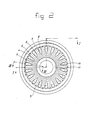
- the shape of the grooves is most clearly seen in Fig. 2.
- the grooves preferably run in zigzag fashion with peaks 5 and troughs 6.
- a number of grooves 7 are provided with a first reflection face 8 and a second reflection face 9.
- the profile of the faces can be seen most clearly in Fig. 3.
- the first reflection face 8 is directed towards the centre line of the reflector and runs parallel to the imaginary line through the starting and finishing point of the curved groove bottom. Through parallel sliding of this face, a correction of the light intensity in the centre of the area to be lit can be made. This correction is accompanied by a slight reduction in light intensity in the wings, in other words, those light rays which form a greater angle with the centre line of the reflector.
- a further correction can be achieved again by the second reflection face 9, which is also directed towards the centre line of the reflector, and which intersects the first reflection face 8 in the centre thereof and runs from the centre through to a point lying between the said intersection line with the first reflection face 8 and a point 10 of the bottom of the groove.
- the above effect can be further increased by setting the angle of this face relative to the centre line of the reflector. In some embodiments it has been found that the said point must coincide with the starting point 11 of the groove.
- the angle of the groove is experimentally determined in such a way that a strong wing shaping of the light intensity distribution occurs. Thereafter, through filling up of the grooves and through selection of the place and degree of filling-up of the grooves, the optimum is sought with regard to as low losses as possible and the sort of influence on the light intensity distribution. When the optimum has been found, a correction to the equipment can be made, with the wall thickness of the reflector at the reflection faces 8 and 9 being equal to that of the remaining part of the reflector.
- the perpendicular of the reflection faces or tangential faces 8 and that of the second reflection faces 9 should preferably be in the same plane as the reflector normal.
Abstract
Description
- The invention relates to a reflector for an oblong light source, comprising a conical part to which a curved part connects, said parts being provided on the inside with longitudinal grooves.
- Light fittings with downward-directed light beams are used, for example, to direct light from the ceiling onto, say, the floor. Here, reflectors are used to direct the light as well as possible onto the object. For point-shaped light sources, virtually ideal reflector forms can be calculated, because point-shaped light sources do not stand in the way of the light beams reflected by the reflector. In particular, light distributions in which the light intensity increases as the angle relative to the centre line of the reflector increases can be achieved. By means of such light intensity distributions, which are also described as wing-shaped, a light intensity distribution which is as uniform as possible can be obtained on the area to be lit, for example the floor.
- Oblong lamps, such as compact fluorescent lamps are not point-shaped and therefore have a light-radiating and, conversely also, a light-absorbing surface which is so large compared with the dimensions of the reflector that the lamp constitutes a hindrance for the light rays coming from the reflector. This means that, without additional measures, only light intensity distributions which are at a maximum at or near the reflector centre line can be obtained.
- In order to obtain a wing-shaped light distribution, applicants have developed a reflector cap, comprising a conical and a curved part. These parts are provided with longitudinal grooves. Viewed in the cross section of the reflector, the said longitudinal grooves are preferably triangular in shape. In this way, the light rays falling on the walls of the grooves are deflected in such a way that they run along the oblong light source and thus contribute to a wing shaping of the light intensity distribution.
- A precise calculation of the light intensity distribution which can be expected is almost impossible due to the multiple reflections, and it would be too inaccurate, while the physical conditions have to be idealised. That is why, for the determination of the light intensity distribution produced by the longitudinal grooves or facets, one is dependent on measurements. Depending on the design of the reflector, it always happens that a further correction of the reflector is hardly possible, for example if material had to be added in the equipment for making the reflector in order to achieve the desired shape. Corrections of the curves of the curved part are very difficult to carry out and give rise to high costs. Despite the great difficulty and the costs, a uniform lighting intensity is not achieved. Moreover, the grooves give rise to a rotationally symmetrical wing-shaped light intensity distribution which means that in a plane perpendicular to the centre line of the lamp a light distribution is produced in which the light intensity is less in the centre than outside the centre.
- The object of the invention is to provide a reflector of the type referred to in the preamble, in which the above-mentioned disadvantages and problems are avoided, or the equipment can be adapted in a simple manner.
- This object is achieved according to the invention in that a number of grooves in the curved reflector part are provided with a reflection face which runs parallel to the line through the starting point and finishing point of the groove bottom of the curved reflector part and is directed towards the centre line of the reflector.
- Through sliding the said reflection face parallel more or less towards or away from the centre line of the reflector, a correction can be made in the centre of the area to be lit which is perpendicular to the centre line of the lamp. This correction is to some extent at the expense of the light intensity in the wings.
- A further correction is preferably compensated for by the fact that the grooves in the conical reflector part, which are in line with the grooves provided with the reflection faces in the curved reflector part, are provided with a second reflection face which is directed towards the centre line of the reflector and runs from the centre of the first reflection face and to a point of the bottom of the groove in the conical reflector part. The optimum compensation can be achieved by making the second reflection face run more or less in the direction of the starting point of the groove in the curved reflector part.
- The invention will be explained in greater detail below with reference to an embodiment illustrated in the drawings, in which:
- Fig. 1 shows a cross section along the line I-I of the reflector according to Fig. 2;
- Fig. 2 shows a bottom view of the reflector according to the invention;
- Fig. 3 shows a cross section along the line III-III of Fig. 2.
- The reflector cap according to Fig. 1 comprises a conical part 1 and a
curved part 2. The reflector cap also has apart 3 which contributes to the light intensity in the wings, but in particular serves as a dazzle screen. The oblong lamp (not shown) must be on the centre line of the reflector cap, while the lower end of the lamp is at the level of the transition between thecurved part 2 and theanti-dazzle part 3 of the reflector cap. On account of the fitting of the lamp, the other end of the lamp will be below the top end of the reflector cap. This fitting and the fastening thereof are not shown, again for the sake of clarity. The inside of thecurved part 2 and the conical part 1 is provided withgrooves 4. These grooves extend at least over the length of the lamp. The shape of the grooves is most clearly seen in Fig. 2. The grooves preferably run in zigzag fashion withpeaks 5 andtroughs 6. A number ofgrooves 7 are provided with a first reflection face 8 and asecond reflection face 9. The profile of the faces can be seen most clearly in Fig. 3. The first reflection face 8 is directed towards the centre line of the reflector and runs parallel to the imaginary line through the starting and finishing point of the curved groove bottom. Through parallel sliding of this face, a correction of the light intensity in the centre of the area to be lit can be made. This correction is accompanied by a slight reduction in light intensity in the wings, in other words, those light rays which form a greater angle with the centre line of the reflector. A further correction can be achieved again by thesecond reflection face 9, which is also directed towards the centre line of the reflector, and which intersects the first reflection face 8 in the centre thereof and runs from the centre through to a point lying between the said intersection line with the first reflection face 8 and apoint 10 of the bottom of the groove. The above effect can be further increased by setting the angle of this face relative to the centre line of the reflector. In some embodiments it has been found that the said point must coincide with thestarting point 11 of the groove. One can determine experimentally how many and/or which grooves must be provided with the said reflection faces 8 and 9. In the embodiment shown with the predetermined dimensions and shape, it was found that an optimum was achieved if the reflection faces are used in every other groove. - In order to permit determination of the optimum experimentally in a simple manner, the procedure is as follows.
- The angle of the groove is experimentally determined in such a way that a strong wing shaping of the light intensity distribution occurs. Thereafter, through filling up of the grooves and through selection of the place and degree of filling-up of the grooves, the optimum is sought with regard to as low losses as possible and the sort of influence on the light intensity distribution. When the optimum has been found, a correction to the equipment can be made, with the wall thickness of the reflector at the reflection faces 8 and 9 being equal to that of the remaining part of the reflector. The perpendicular of the reflection faces or tangential faces 8 and that of the
second reflection faces 9 should preferably be in the same plane as the reflector normal. - It was found that a uniform light intensity distribution on a face perpendicular to the centre line of the reflector can be achieved with imorovement of the original output.
Claims (2)
Priority Applications (1)
| Application Number | Priority Date | Filing Date | Title |
|---|---|---|---|
| AT87200942T ATE49649T1 (en) | 1986-05-26 | 1987-05-19 | REFLECTOR FOR AN EXTENDED LIGHT SOURCE. |
Applications Claiming Priority (2)
| Application Number | Priority Date | Filing Date | Title |
|---|---|---|---|
| NL8601338 | 1986-05-26 | ||
| NL8601338A NL8601338A (en) | 1986-05-26 | 1986-05-26 | REFLECTOR FOR AN LONG-LIGHT SOURCE. |
Publications (2)
| Publication Number | Publication Date |
|---|---|
| EP0247683A1 true EP0247683A1 (en) | 1987-12-02 |
| EP0247683B1 EP0247683B1 (en) | 1990-01-17 |
Family
ID=19848068
Family Applications (1)
| Application Number | Title | Priority Date | Filing Date |
|---|---|---|---|
| EP87200942A Expired - Lifetime EP0247683B1 (en) | 1986-05-26 | 1987-05-19 | Reflector for an oblong light source |
Country Status (8)
| Country | Link |
|---|---|
| US (1) | US4761721A (en) |
| EP (1) | EP0247683B1 (en) |
| AT (1) | ATE49649T1 (en) |
| CA (1) | CA1281695C (en) |
| DE (1) | DE3761460D1 (en) |
| ES (1) | ES2012385B3 (en) |
| GR (1) | GR3000314T3 (en) |
| NL (1) | NL8601338A (en) |
Families Citing this family (27)
| Publication number | Priority date | Publication date | Assignee | Title |
|---|---|---|---|---|
| JPH0729513Y2 (en) * | 1988-04-06 | 1995-07-05 | セイコーエプソン株式会社 | Electronic clock circuit |
| US5287259A (en) * | 1991-11-27 | 1994-02-15 | Lorin Industries, Inc. | Light reflector assembly |
| US5733030A (en) * | 1996-08-01 | 1998-03-31 | Cohn; Michael | Light reflector |
| CN2499698Y (en) * | 2001-06-27 | 2002-07-10 | 上海威廉照明电气有限公司 | Shooting lamp body suitable for strip light source |
| US7198389B1 (en) * | 2004-09-27 | 2007-04-03 | Regal King Comercial Offshore De Macau Limitada | Lamp with spot light and flood light features |
| US7985005B2 (en) * | 2006-05-30 | 2011-07-26 | Journée Lighting, Inc. | Lighting assembly and light module for same |
| US20080055923A1 (en) * | 2006-09-06 | 2008-03-06 | Miller Jack V | High efficiency light projector |
| US7866850B2 (en) | 2008-02-26 | 2011-01-11 | Journée Lighting, Inc. | Light fixture assembly and LED assembly |
| US8152336B2 (en) * | 2008-11-21 | 2012-04-10 | Journée Lighting, Inc. | Removable LED light module for use in a light fixture assembly |
| WO2011019945A1 (en) | 2009-08-12 | 2011-02-17 | Journee Lighting, Inc. | Led light module for use in a lighting assembly |
| US8125776B2 (en) | 2010-02-23 | 2012-02-28 | Journée Lighting, Inc. | Socket and heat sink unit for use with removable LED light module |
| JP5467547B2 (en) * | 2010-03-05 | 2014-04-09 | パナソニック株式会社 | lighting equipment |
| USD669210S1 (en) | 2011-05-06 | 2012-10-16 | RAB Lighting Inc. | Dome LED housing |
| US9565782B2 (en) | 2013-02-15 | 2017-02-07 | Ecosense Lighting Inc. | Field replaceable power supply cartridge |
| US9188312B2 (en) * | 2013-03-14 | 2015-11-17 | GE Lighting Solutions, LLC | Optical system for a directional lamp |
| US10477636B1 (en) | 2014-10-28 | 2019-11-12 | Ecosense Lighting Inc. | Lighting systems having multiple light sources |
| US11306897B2 (en) | 2015-02-09 | 2022-04-19 | Ecosense Lighting Inc. | Lighting systems generating partially-collimated light emissions |
| US9869450B2 (en) | 2015-02-09 | 2018-01-16 | Ecosense Lighting Inc. | Lighting systems having a truncated parabolic- or hyperbolic-conical light reflector, or a total internal reflection lens; and having another light reflector |
| US9568665B2 (en) | 2015-03-03 | 2017-02-14 | Ecosense Lighting Inc. | Lighting systems including lens modules for selectable light distribution |
| US9651216B2 (en) | 2015-03-03 | 2017-05-16 | Ecosense Lighting Inc. | Lighting systems including asymmetric lens modules for selectable light distribution |
| US9746159B1 (en) | 2015-03-03 | 2017-08-29 | Ecosense Lighting Inc. | Lighting system having a sealing system |
| US9651227B2 (en) | 2015-03-03 | 2017-05-16 | Ecosense Lighting Inc. | Low-profile lighting system having pivotable lighting enclosure |
| USD785218S1 (en) | 2015-07-06 | 2017-04-25 | Ecosense Lighting Inc. | LED luminaire having a mounting system |
| USD782094S1 (en) | 2015-07-20 | 2017-03-21 | Ecosense Lighting Inc. | LED luminaire having a mounting system |
| USD782093S1 (en) | 2015-07-20 | 2017-03-21 | Ecosense Lighting Inc. | LED luminaire having a mounting system |
| US9651232B1 (en) | 2015-08-03 | 2017-05-16 | Ecosense Lighting Inc. | Lighting system having a mounting device |
| USD930200S1 (en) * | 2019-07-04 | 2021-09-07 | Kellermann Gmbh | Light for vehicles |
Citations (4)
| Publication number | Priority date | Publication date | Assignee | Title |
|---|---|---|---|---|
| DE431750C (en) * | 1922-06-13 | 1926-07-20 | Ruthardt Weinert | Lighting device |
| US1738426A (en) * | 1928-03-10 | 1929-12-03 | Sunshine Inc | Light reflector |
| US3701898A (en) * | 1970-07-29 | 1972-10-31 | Esquire Inc | Light reflector system |
| US4021659A (en) * | 1975-10-30 | 1977-05-03 | General Electric Company | Projector lamp reflector |
Family Cites Families (6)
| Publication number | Priority date | Publication date | Assignee | Title |
|---|---|---|---|---|
| US1841917A (en) * | 1929-03-21 | 1932-01-19 | Schimpff Eugene | Headlight reflector |
| US3329812A (en) * | 1965-03-08 | 1967-07-04 | Mc Graw Edison Co | Luminaire optical assembly |
| US3662165A (en) * | 1970-03-02 | 1972-05-09 | Gen Electric | Luminaire reflector |
| US3705302A (en) * | 1971-03-12 | 1972-12-05 | Gen Electric | Luminaire |
| FR2460442A1 (en) * | 1979-06-29 | 1981-01-23 | Cibie Projecteurs | NEW PROJECTOR STRUCTURE, IN PARTICULAR OF AUTOMOTIVE PROJECTOR |
| JPS5645507A (en) * | 1979-09-21 | 1981-04-25 | Toshiba Electric Equip | Lighting device |
-
1986
- 1986-05-26 NL NL8601338A patent/NL8601338A/en not_active Application Discontinuation
-
1987
- 1987-05-19 AT AT87200942T patent/ATE49649T1/en not_active IP Right Cessation
- 1987-05-19 EP EP87200942A patent/EP0247683B1/en not_active Expired - Lifetime
- 1987-05-19 DE DE8787200942T patent/DE3761460D1/en not_active Expired - Fee Related
- 1987-05-19 ES ES87200942T patent/ES2012385B3/en not_active Expired - Lifetime
- 1987-05-22 US US07/053,345 patent/US4761721A/en not_active Expired - Fee Related
- 1987-05-26 CA CA000538037A patent/CA1281695C/en not_active Expired - Lifetime
-
1990
- 1990-01-19 GR GR90400032T patent/GR3000314T3/en unknown
Patent Citations (4)
| Publication number | Priority date | Publication date | Assignee | Title |
|---|---|---|---|---|
| DE431750C (en) * | 1922-06-13 | 1926-07-20 | Ruthardt Weinert | Lighting device |
| US1738426A (en) * | 1928-03-10 | 1929-12-03 | Sunshine Inc | Light reflector |
| US3701898A (en) * | 1970-07-29 | 1972-10-31 | Esquire Inc | Light reflector system |
| US4021659A (en) * | 1975-10-30 | 1977-05-03 | General Electric Company | Projector lamp reflector |
Also Published As
| Publication number | Publication date |
|---|---|
| NL8601338A (en) | 1987-12-16 |
| ATE49649T1 (en) | 1990-02-15 |
| ES2012385B3 (en) | 1990-03-16 |
| EP0247683B1 (en) | 1990-01-17 |
| DE3761460D1 (en) | 1990-02-22 |
| GR3000314T3 (en) | 1991-06-07 |
| US4761721A (en) | 1988-08-02 |
| CA1281695C (en) | 1991-03-19 |
Similar Documents
| Publication | Publication Date | Title |
|---|---|---|
| EP0247683B1 (en) | Reflector for an oblong light source | |
| US4539628A (en) | Nonglare light fixtures for a rod-shaped light source | |
| US6443598B1 (en) | Lighting appliance with glare reducing cross blades | |
| US5136491A (en) | Reflector for a lamp and method of determining the form of a reflector | |
| EP0317291A2 (en) | Automotive lighting element | |
| EP0201926B1 (en) | Indirect mirror light fixture | |
| US4888668A (en) | Mirror light unit | |
| US5544021A (en) | Motor vehicle headlight including a two-filament lamp for selectively generating a main beam and an anti-fog beam | |
| EP0318908A2 (en) | An improved luminaire with uplight control | |
| CA2180712C (en) | Lighting fixture having a parabolic louver | |
| US4731713A (en) | Fog lamp | |
| US4368504A (en) | Task lighting apparatus | |
| US4621309A (en) | Elongated luminaire | |
| JPH0320902A (en) | Headlight with inclined lens including flute for diverting beam | |
| DE69735168T2 (en) | FLOOD LIGHT OR LUMINAIRE CONSTRUCTION | |
| US5944411A (en) | Luminaire slat with v-shaped cross section | |
| US4683526A (en) | Asymmetric lamp | |
| US20010019481A1 (en) | Luminaire for elongate lamp | |
| US4071750A (en) | Light diffuser and lamp incorporating the same | |
| US4293900A (en) | Luminaire reflector | |
| US6325529B1 (en) | Vehicle lamp with shade having reflector following edge | |
| EP0741262A2 (en) | A vehicle headlight comprising a worked reflecting surface for shaping the light beam through reflection | |
| US5678922A (en) | Lighting fixture and anodized metallic louver system therefor | |
| CN210831829U (en) | Line source integrated transition reflecting assembly and lamp thereof | |
| ITRM980753A1 (en) | SIGNAL LIGHT WITH CONTROLLED LIGHTING OF THE ILLUMINAN TE FIELD, AND PROCEDURE FOR THE PRODUCTION OF A CURVED ELEMENT OF SUCH |
Legal Events
| Date | Code | Title | Description |
|---|---|---|---|
| PUAI | Public reference made under article 153(3) epc to a published international application that has entered the european phase |
Free format text: ORIGINAL CODE: 0009012 |
|
| AK | Designated contracting states |
Kind code of ref document: A1 Designated state(s): AT BE CH DE ES FR GB GR IT LI LU NL SE |
|
| 17P | Request for examination filed |
Effective date: 19871230 |
|
| 17Q | First examination report despatched |
Effective date: 19881024 |
|
| GRAA | (expected) grant |
Free format text: ORIGINAL CODE: 0009210 |
|
| AK | Designated contracting states |
Kind code of ref document: B1 Designated state(s): AT BE CH DE ES FR GB GR IT LI LU NL SE |
|
| REF | Corresponds to: |
Ref document number: 49649 Country of ref document: AT Date of ref document: 19900215 Kind code of ref document: T |
|
| ITF | It: translation for a ep patent filed |
Owner name: JACOBACCI & PERANI S.P.A. |
|
| REF | Corresponds to: |
Ref document number: 3761460 Country of ref document: DE Date of ref document: 19900222 |
|
| ET | Fr: translation filed | ||
| REG | Reference to a national code |
Ref country code: GR Ref legal event code: FG4A Free format text: 3000314 |
|
| PLBE | No opposition filed within time limit |
Free format text: ORIGINAL CODE: 0009261 |
|
| STAA | Information on the status of an ep patent application or granted ep patent |
Free format text: STATUS: NO OPPOSITION FILED WITHIN TIME LIMIT |
|
| 26N | No opposition filed | ||
| ITTA | It: last paid annual fee | ||
| REG | Reference to a national code |
Ref country code: GB Ref legal event code: 732 |
|
| ITPR | It: changes in ownership of a european patent |
Owner name: CESSIONE;RAAK LICHT B.V. |
|
| NLS | Nl: assignments of ep-patents |
Owner name: RAAK LICHT B.V. TE HOOGEZAND-SAPPEMEER. |
|
| REG | Reference to a national code |
Ref country code: FR Ref legal event code: TP |
|
| PGFP | Annual fee paid to national office [announced via postgrant information from national office to epo] |
Ref country code: GB Payment date: 19940519 Year of fee payment: 8 |
|
| PGFP | Annual fee paid to national office [announced via postgrant information from national office to epo] |
Ref country code: FR Payment date: 19940524 Year of fee payment: 8 |
|
| PGFP | Annual fee paid to national office [announced via postgrant information from national office to epo] |
Ref country code: SE Payment date: 19940525 Year of fee payment: 8 Ref country code: CH Payment date: 19940525 Year of fee payment: 8 |
|
| PGFP | Annual fee paid to national office [announced via postgrant information from national office to epo] |
Ref country code: GR Payment date: 19940527 Year of fee payment: 8 |
|
| PGFP | Annual fee paid to national office [announced via postgrant information from national office to epo] |
Ref country code: NL Payment date: 19940531 Year of fee payment: 8 |
|
| PGFP | Annual fee paid to national office [announced via postgrant information from national office to epo] |
Ref country code: DE Payment date: 19940608 Year of fee payment: 8 |
|
| PGFP | Annual fee paid to national office [announced via postgrant information from national office to epo] |
Ref country code: AT Payment date: 19940620 Year of fee payment: 8 |
|
| PGFP | Annual fee paid to national office [announced via postgrant information from national office to epo] |
Ref country code: LU Payment date: 19940630 Year of fee payment: 8 |
|
| PGFP | Annual fee paid to national office [announced via postgrant information from national office to epo] |
Ref country code: BE Payment date: 19940711 Year of fee payment: 8 |
|
| EPTA | Lu: last paid annual fee | ||
| PGFP | Annual fee paid to national office [announced via postgrant information from national office to epo] |
Ref country code: ES Payment date: 19941130 Year of fee payment: 8 |
|
| EAL | Se: european patent in force in sweden |
Ref document number: 87200942.8 |
|
| PG25 | Lapsed in a contracting state [announced via postgrant information from national office to epo] |
Ref country code: LU Free format text: LAPSE BECAUSE OF NON-PAYMENT OF DUE FEES Effective date: 19950519 Ref country code: GB Effective date: 19950519 Ref country code: AT Effective date: 19950519 |
|
| PG25 | Lapsed in a contracting state [announced via postgrant information from national office to epo] |
Ref country code: SE Effective date: 19950520 Ref country code: ES Free format text: LAPSE BECAUSE OF NON-PAYMENT OF DUE FEES Effective date: 19950520 |
|
| PG25 | Lapsed in a contracting state [announced via postgrant information from national office to epo] |
Ref country code: LI Effective date: 19950531 Ref country code: CH Effective date: 19950531 Ref country code: BE Effective date: 19950531 |
|
| BERE | Be: lapsed |
Owner name: RAAK LICHT B.V. Effective date: 19950531 |
|
| PG25 | Lapsed in a contracting state [announced via postgrant information from national office to epo] |
Ref country code: GR Free format text: THE PATENT HAS BEEN ANNULLED BY A DECISION OF A NATIONAL AUTHORITY Effective date: 19951130 |
|
| PG25 | Lapsed in a contracting state [announced via postgrant information from national office to epo] |
Ref country code: NL Effective date: 19951201 |
|
| GBPC | Gb: european patent ceased through non-payment of renewal fee |
Effective date: 19950519 |
|
| REG | Reference to a national code |
Ref country code: CH Ref legal event code: PL |
|
| NLV4 | Nl: lapsed or anulled due to non-payment of the annual fee |
Effective date: 19951201 |
|
| PG25 | Lapsed in a contracting state [announced via postgrant information from national office to epo] |
Ref country code: DE Effective date: 19960201 |
|
| EUG | Se: european patent has lapsed |
Ref document number: 87200942.8 |
|
| PG25 | Lapsed in a contracting state [announced via postgrant information from national office to epo] |
Ref country code: FR Effective date: 19960229 |
|
| REG | Reference to a national code |
Ref country code: GR Ref legal event code: MM2A Free format text: 3000314 |
|
| REG | Reference to a national code |
Ref country code: FR Ref legal event code: ST |
|
| REG | Reference to a national code |
Ref country code: FR Ref legal event code: ST |
|
| REG | Reference to a national code |
Ref country code: ES Ref legal event code: FD2A Effective date: 19990301 |
|
| PG25 | Lapsed in a contracting state [announced via postgrant information from national office to epo] |
Ref country code: IT Free format text: LAPSE BECAUSE OF NON-PAYMENT OF DUE FEES;WARNING: LAPSES OF ITALIAN PATENTS WITH EFFECTIVE DATE BEFORE 2007 MAY HAVE OCCURRED AT ANY TIME BEFORE 2007. THE CORRECT EFFECTIVE DATE MAY BE DIFFERENT FROM THE ONE RECORDED. Effective date: 20050519 |