EP0247876A2 - Storage and dispensing means - Google Patents
Storage and dispensing means Download PDFInfo
- Publication number
- EP0247876A2 EP0247876A2 EP87304738A EP87304738A EP0247876A2 EP 0247876 A2 EP0247876 A2 EP 0247876A2 EP 87304738 A EP87304738 A EP 87304738A EP 87304738 A EP87304738 A EP 87304738A EP 0247876 A2 EP0247876 A2 EP 0247876A2
- Authority
- EP
- European Patent Office
- Prior art keywords
- bin
- storage
- dispensing means
- compartment
- cassette
- Prior art date
- Legal status (The legal status is an assumption and is not a legal conclusion. Google has not performed a legal analysis and makes no representation as to the accuracy of the status listed.)
- Granted
Links
- 230000037431 insertion Effects 0.000 claims abstract description 5
- 238000003780 insertion Methods 0.000 claims abstract description 5
- 210000002105 tongue Anatomy 0.000 claims description 12
- 230000015572 biosynthetic process Effects 0.000 claims description 7
- 238000005755 formation reaction Methods 0.000 claims description 7
- 230000000717 retained effect Effects 0.000 claims description 4
- 230000011664 signaling Effects 0.000 claims description 2
- 239000012780 transparent material Substances 0.000 claims description 2
- 230000005484 gravity Effects 0.000 description 2
- 230000003993 interaction Effects 0.000 description 1
- 239000000463 material Substances 0.000 description 1
- 239000004033 plastic Substances 0.000 description 1
- 229920003023 plastic Polymers 0.000 description 1
Images


Classifications
-
- G—PHYSICS
- G11—INFORMATION STORAGE
- G11B—INFORMATION STORAGE BASED ON RELATIVE MOVEMENT BETWEEN RECORD CARRIER AND TRANSDUCER
- G11B15/00—Driving, starting or stopping record carriers of filamentary or web form; Driving both such record carriers and heads; Guiding such record carriers or containers therefor; Control thereof; Control of operating function
- G11B15/675—Guiding containers, e.g. loading, ejecting cassettes
- G11B15/68—Automatic cassette changing arrangements; automatic tape changing arrangements
- G11B15/682—Automatic cassette changing arrangements; automatic tape changing arrangements with fixed magazines having fixed cassette storage cells, e.g. in racks
- G11B15/6825—Details of magazines, e.g. removable, adapted for cassettes of different sizes
-
- G—PHYSICS
- G11—INFORMATION STORAGE
- G11B—INFORMATION STORAGE BASED ON RELATIVE MOVEMENT BETWEEN RECORD CARRIER AND TRANSDUCER
- G11B23/00—Record carriers not specific to the method of recording or reproducing; Accessories, e.g. containers, specially adapted for co-operation with the recording or reproducing apparatus ; Intermediate mediums; Apparatus or processes specially adapted for their manufacture
- G11B23/02—Containers; Storing means both adapted to cooperate with the recording or reproducing means
- G11B23/023—Containers for magazines or cassettes
- G11B23/0236—Containers for several cassettes
-
- Y—GENERAL TAGGING OF NEW TECHNOLOGICAL DEVELOPMENTS; GENERAL TAGGING OF CROSS-SECTIONAL TECHNOLOGIES SPANNING OVER SEVERAL SECTIONS OF THE IPC; TECHNICAL SUBJECTS COVERED BY FORMER USPC CROSS-REFERENCE ART COLLECTIONS [XRACs] AND DIGESTS
- Y10—TECHNICAL SUBJECTS COVERED BY FORMER USPC
- Y10S—TECHNICAL SUBJECTS COVERED BY FORMER USPC CROSS-REFERENCE ART COLLECTIONS [XRACs] AND DIGESTS
- Y10S194/00—Check-actuated control mechanisms
- Y10S194/906—Video cassette vendor
Definitions
- THIS INVENTION relates to storage and dispensing means for cassette dispensing machines.
- this invention relates to the means for holding the cassettes in a dispensing machine and for releasing them for access by a user.
- a wide variety of such means are known, including tilting doors and pivoting doors which open to allow access to a cupboard-like compartment, and carousel-type means by which the tapes are held in a drum magazine.
- storage and dispensing means comprising a bin having a plurality of sliding compartments each arranged to receive a tape cassette side by side therein, the compartments being slidable in their own planes between a closed position within the bin in which the compartment interior is inaccessible for removal of a cassette, and a position extended from a side of the bin in which the compartments are accessible for removal and insertion of a cassette.
- a feature of the invention provides for compartments to have a side opening therein which is accessible for removal and insertion of a cassette when the cassette is in the extended position, and inaccessible when within the bin by reason of the proximity of a sufficiently closed side of an adjoining compartment.
- the side opening is in a major side of the compartment, and the major side opposite the open side has sufficient opening therein to allow a user to push a cassette out of the open side of the compartment from the said opposite side.
- each compartment is also provided for each compartment to be retained in its closed position against a biasing force by a locking pin, mounted on the back of the bin, and further for the compartments to have runners extending rearwardly from the upper and lower sides through openings in the back of the bin.
- the runners and the upper and lower edges of the compartments may slide between pairs of ridges in the upper and lower bin surface, and the runners have clips on the rear side of the bin arranged for preventing removal of the compartment from the front side of the bin and for determining the extent of extension of the compartments out of the bin.
- the compartments have openings in their rear sides arranged to allow access between cassette recognition means at the bin rear and a cassette in a compartment in use, and the compartments have formations arranged to locate a cassette in a predetermined position therein.
- a locking pin may be provided to be operable to extend into and retract from a co-operating hole in a runner of the compartment.
- the locking pin preferably is part of a solenoid, and the rear of the pin is arranged to activate a signalling switch when in a retracted position.
- the biasing means for each compartment may be a leaf spring mounted on the inside rear surface of the bin in the length of the compartment and arranged to react against the rear sides of the compartment.
- the compartment is of transparent material.
- the bin may have an electronics printed circuit board mounted on its outside rear surface, carrying electronic circuiting for operating each locking pin on the bin.
- a particular feature of the invention provides for the bin to have mounting formations exdtending rearwardly from the upper and lower bin sides, and being arranged to mount the bin in a housing framework of the tape cassette dispensing machine.
- the mounting formations are two tongues extending from each of the upper and lower bin sides forming two pairs of tongues operatively one above the other, each tongue having an opening through it with a slot extending from the opening through the rear edge.
- each rod For mounting the bin in a framework, there is provided a locking rod for each pair of mounting tongues, each rod having two spaced apart thickened portions and being arranged to allow the narrow portion to be transversely insertable into the openings of a pair through the slots and being slidable to have the thickened portion within the opening in which position the slots are too narrow to allow transverse withdrawal through the slots.
- the invention extends to a tape cassette dispensing machine comprising a framework fitted with rows and columns of storage and dispensing means as defined above, there being a locking rod for each column of bins.
- a bin (1) is rectangular in shape having two opposite major sides with one being a rear side (2) and the other a front side (3) which is open.
- the top and bottom sides (4) and (5) of the bin each have two rearwardly projecting co-planar tongues (6), with openings (7) therein with slots (8) running from the openings to the rearmost edges of the tongues.
- the tongues form two vertically aligned upper and lower pairs (9).
- the bin has spaced apart ribs (10) on the inside upper and lower surfaces to act as guides for receiving slidable compartments (11) in side-by-side manner along the length of the bin.
- Each compartment (11) is rectangular and of a size that will enable it to receive a video tape cassette (not shown) neatly therein with a pin (12) locating one of the spools of the tape.
- the compartment is of clear plastics material, having one major side (14) open and having a central opening (16) in the other major side which carries the pin (12).
- Top and bottom runners (18) are provided on the compartment (11), and these extend rearwardly from and co-planarly with the top and bottom ends of the compartment, and pass through slots (20) in the top and bottom of the rear of the bin, to enable the cassette compartment to slide in and out of the bin between the spaced apart guide ribs (10) with the runners (18) still retained within their slots (20).
- the runners (18) are provided with clip formations (22) to prevent the compartment from being withdrawn completely from the bin.
- a suitable handle (24) is provided on the front edge of the compartment, and an opening (26) is provided in the central portion of the rear edge of the compartment, to allow for electronic interaction between means for recognising the presence of a cassette, and the cassette itself when located in the compartment.
- a wide variety of such means are known in the art.
- a leaf spring (28) is located at the rear of the bin opposite the position and in the length of each of the compartments, so that a compartment can be slid closed against the spring biasing (28), to having its front edge flush with the bin.
- a solenoid pin hole (30) in the bottom runner of each is engagable by a solenoid pin (32) ( Figure 2) moving under force of gravity, as the compartment is pushed closed. The compartment is thus locked in the closed position inside the bin.
- the solenoid pin (32) runs through the length of a solenoid (34), and when the solenoid is activated to retract the pin upwardly it releases the compartment under spring biasing to slide out of the bin.
- the top end (36) of the retracted pin operates a microswitch (38), to provide a feedback electrical signal to the dispensing machine control means indicating that release of the particular compartment has taken place.
- the microswitch (38) is mounted to a printed circuit board (39) fitted against the outside rear of the bin.
- Locking rods (40) are provided and they pass through the openings (7) of each pair (9) of top and bottom tongues (6), and have outwardly stepped diametrical sections (42) which fit neatly within the openings (7) of each pair, but which are too large to slide transversely out of the slots (8).
- the bin can be transversely retracted from any cabinet holding it, with the rods sliding out of the slots (8).
- a cassette can be located inside the compartment quite conveniently through the open major side thereof, and removed by pushing a finger through the central opening (16) in the opposite compartment side, to push the cassette out through the opposite open side.
- the compartment is conveniently slid into the bin whether empty or closed, to have the solenoid pin lock under gravity in the pin opening. It will be appreciated that when the bin is fully fitted with compartment (11), no access to the compartment contents is possible.
- compartment upper and lower edges are tapered towards each other very slightly from front to rear to facilitate the slidability within the bin.
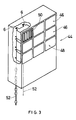
- a cabinet (44) of a video cassette dispensing machine is shown.
- the cabinet comprises a reactangular box framework providing housing for rows (46) and columns (48) of bins (50) as described with reference to Figures 1 and 2.
- the bins slide into each box frame and bins of a column are retained in position by locking rods (52) running the height of the cabinet.
- each bin of column is freed or locked by axially sliding the rods of that column to the appropriate position as described with reference to Figures 1 and 2.
- the invention provides a simple and compact storage and dispensing means.
Abstract
Description
- THIS INVENTION relates to storage and dispensing means for cassette dispensing machines.
- Particularly this invention relates to the means for holding the cassettes in a dispensing machine and for releasing them for access by a user. A wide variety of such means are known, including tilting doors and pivoting doors which open to allow access to a cupboard-like compartment, and carousel-type means by which the tapes are held in a drum magazine.
- It is a object of this invention to provide a storage and dispensing means for cassette dispensing machines, which will operate and be effective in as a storage medium.
- In accordance with this invention there is provided storage and dispensing means comprising a bin having a plurality of sliding compartments each arranged to receive a tape cassette side by side therein, the compartments being slidable in their own planes between a closed position within the bin in which the compartment interior is inaccessible for removal of a cassette, and a position extended from a side of the bin in which the compartments are accessible for removal and insertion of a cassette.
- A feature of the invention provides for compartments to have a side opening therein which is accessible for removal and insertion of a cassette when the cassette is in the extended position, and inaccessible when within the bin by reason of the proximity of a sufficiently closed side of an adjoining compartment.
- Preferably the side opening is in a major side of the compartment, and the major side opposite the open side has sufficient opening therein to allow a user to push a cassette out of the open side of the compartment from the said opposite side.
- There is also provided for each compartment to be retained in its closed position against a biasing force by a locking pin, mounted on the back of the bin, and further for the compartments to have runners extending rearwardly from the upper and lower sides through openings in the back of the bin.
- The runners and the upper and lower edges of the compartments may slide between pairs of ridges in the upper and lower bin surface, and the runners have clips on the rear side of the bin arranged for preventing removal of the compartment from the front side of the bin and for determining the extent of extension of the compartments out of the bin.
- Further, preferably the compartments have openings in their rear sides arranged to allow access between cassette recognition means at the bin rear and a cassette in a compartment in use, and the compartments have formations arranged to locate a cassette in a predetermined position therein.
- A locking pin may be provided to be operable to extend into and retract from a co-operating hole in a runner of the compartment. The locking pin preferably is part of a solenoid, and the rear of the pin is arranged to activate a signalling switch when in a retracted position.
- The biasing means for each compartment may be a leaf spring mounted on the inside rear surface of the bin in the length of the compartment and arranged to react against the rear sides of the compartment.
- Preferably the compartment is of transparent material.
- The bin may have an electronics printed circuit board mounted on its outside rear surface, carrying electronic circuiting for operating each locking pin on the bin.
- A particular feature of the invention provides for the bin to have mounting formations exdtending rearwardly from the upper and lower bin sides, and being arranged to mount the bin in a housing framework of the tape cassette dispensing machine.
- The mounting formations are two tongues extending from each of the upper and lower bin sides forming two pairs of tongues operatively one above the other, each tongue having an opening through it with a slot extending from the opening through the rear edge.
- For mounting the bin in a framework, there is provided a locking rod for each pair of mounting tongues, each rod having two spaced apart thickened portions and being arranged to allow the narrow portion to be transversely insertable into the openings of a pair through the slots and being slidable to have the thickened portion within the opening in which position the slots are too narrow to allow transverse withdrawal through the slots.
- The invention extends to a tape cassette dispensing machine comprising a framework fitted with rows and columns of storage and dispensing means as defined above, there being a locking rod for each column of bins.
- A preferred embodiment of the invention is described below by way of example only, and with reference to the accompanying drawings, in which:
- Figure 1 is an isometric view of a bin and compartment according to the invention;
- Figure 2 is a side view of the embodiment of Figure 1; and,
- Figure 3 is an isometric view of a tape cassette dispensing machine fitted with the embodiment of Figures 1 and 2.
- Referring to Figures 1 and 2, a bin (1) is rectangular in shape having two opposite major sides with one being a rear side (2) and the other a front side (3) which is open. The top and bottom sides (4) and (5) of the bin each have two rearwardly projecting co-planar tongues (6), with openings (7) therein with slots (8) running from the openings to the rearmost edges of the tongues. The tongues form two vertically aligned upper and lower pairs (9).
- The bin has spaced apart ribs (10) on the inside upper and lower surfaces to act as guides for receiving slidable compartments (11) in side-by-side manner along the length of the bin.
- Each compartment (11) is rectangular and of a size that will enable it to receive a video tape cassette (not shown) neatly therein with a pin (12) locating one of the spools of the tape. The compartment is of clear plastics material, having one major side (14) open and having a central opening (16) in the other major side which carries the pin (12). Top and bottom runners (18) are provided on the compartment (11), and these extend rearwardly from and co-planarly with the top and bottom ends of the compartment, and pass through slots (20) in the top and bottom of the rear of the bin, to enable the cassette compartment to slide in and out of the bin between the spaced apart guide ribs (10) with the runners (18) still retained within their slots (20). The runners (18) are provided with clip formations (22) to prevent the compartment from being withdrawn completely from the bin. A suitable handle (24) is provided on the front edge of the compartment, and an opening (26) is provided in the central portion of the rear edge of the compartment, to allow for electronic interaction between means for recognising the presence of a cassette, and the cassette itself when located in the compartment. A wide variety of such means are known in the art.
- A leaf spring (28) is located at the rear of the bin opposite the position and in the length of each of the compartments, so that a compartment can be slid closed against the spring biasing (28), to having its front edge flush with the bin. A solenoid pin hole (30) in the bottom runner of each is engagable by a solenoid pin (32) (Figure 2) moving under force of gravity, as the compartment is pushed closed. The compartment is thus locked in the closed position inside the bin. The solenoid pin (32) runs through the length of a solenoid (34), and when the solenoid is activated to retract the pin upwardly it releases the compartment under spring biasing to slide out of the bin. Simultaneously the top end (36) of the retracted pin operates a microswitch (38), to provide a feedback electrical signal to the dispensing machine control means indicating that release of the particular compartment has taken place. The microswitch (38) is mounted to a printed circuit board (39) fitted against the outside rear of the bin.
- Locking rods (40) are provided and they pass through the openings (7) of each pair (9) of top and bottom tongues (6), and have outwardly stepped diametrical sections (42) which fit neatly within the openings (7) of each pair, but which are too large to slide transversely out of the slots (8). Thus when the rods are shifted axially to have the thinner portion of the rods located in the opening (7), the bin can be transversely retracted from any cabinet holding it, with the rods sliding out of the slots (8).
- A cassette can be located inside the compartment quite conveniently through the open major side thereof, and removed by pushing a finger through the central opening (16) in the opposite compartment side, to push the cassette out through the opposite open side. The compartment is conveniently slid into the bin whether empty or closed, to have the solenoid pin lock under gravity in the pin opening. It will be appreciated that when the bin is fully fitted with compartment (11), no access to the compartment contents is possible.
- Preferably the compartment upper and lower edges are tapered towards each other very slightly from front to rear to facilitate the slidability within the bin.
- Referring to Figure 3, a cabinet (44) of a video cassette dispensing machine is shown. the cabinet comprises a reactangular box framework providing housing for rows (46) and columns (48) of bins (50) as described with reference to Figures 1 and 2. The bins slide into each box frame and bins of a column are retained in position by locking rods (52) running the height of the cabinet. Thus each bin of column is freed or locked by axially sliding the rods of that column to the appropriate position as described with reference to Figures 1 and 2.
- It is considered that the invention provides a simple and compact storage and dispensing means.
Claims (20)
Applications Claiming Priority (2)
| Application Number | Priority Date | Filing Date | Title |
|---|---|---|---|
| ZA864044 | 1986-05-30 | ||
| ZA864044 | 1986-05-30 |
Publications (3)
| Publication Number | Publication Date |
|---|---|
| EP0247876A2 true EP0247876A2 (en) | 1987-12-02 |
| EP0247876A3 EP0247876A3 (en) | 1989-02-01 |
| EP0247876B1 EP0247876B1 (en) | 1992-05-06 |
Family
ID=25578424
Family Applications (1)
| Application Number | Title | Priority Date | Filing Date |
|---|---|---|---|
| EP87304738A Expired - Lifetime EP0247876B1 (en) | 1986-05-30 | 1987-05-28 | Storage and dispensing means |
Country Status (4)
| Country | Link |
|---|---|
| US (1) | US4821917A (en) |
| EP (1) | EP0247876B1 (en) |
| AU (1) | AU601189B2 (en) |
| DE (1) | DE3778757D1 (en) |
Cited By (11)
| Publication number | Priority date | Publication date | Assignee | Title |
|---|---|---|---|---|
| US5038235A (en) * | 1988-06-17 | 1991-08-06 | Matsushita Electric Industrial Co., Ltd. | Superposed tape cassette storage racks with pusher unit facilitating tape withdrawal |
| FR2662293A1 (en) * | 1990-05-16 | 1991-11-22 | Technicatome | Modular system for consulting information carriers such as discs or cassettes |
| EP0619713A4 (en) * | 1991-04-03 | 1994-06-13 | Engineered Data Products Inc | High-density storage rack system for magnetic data storage tape cartridges. |
| GB2313038B (en) * | 1996-05-13 | 2000-04-05 | Core Techn Inc | Apparatus for media storage |
| EP2363798A1 (en) * | 2004-04-15 | 2011-09-07 | Redbox Automated Retail, LLC | Article dispensing system and method for same |
| US9286617B2 (en) | 2011-08-12 | 2016-03-15 | Redbox Automated Retail, Llc | System and method for applying parental control limits from content providers to media content |
| US9489691B2 (en) | 2009-09-05 | 2016-11-08 | Redbox Automated Retail, Llc | Article vending machine and method for exchanging an inoperable article for an operable article |
| US9524368B2 (en) | 2004-04-15 | 2016-12-20 | Redbox Automated Retail, Llc | System and method for communicating vending information |
| US9542661B2 (en) | 2009-09-05 | 2017-01-10 | Redbox Automated Retail, Llc | Article vending machine and method for exchanging an inoperable article for an operable article |
| US9582954B2 (en) | 2010-08-23 | 2017-02-28 | Redbox Automated Retail, Llc | Article vending machine and method for authenticating received articles |
| US9785996B2 (en) | 2011-06-14 | 2017-10-10 | Redbox Automated Retail, Llc | System and method for substituting a media article with alternative media |
Families Citing this family (17)
| Publication number | Priority date | Publication date | Assignee | Title |
|---|---|---|---|---|
| US5370265A (en) * | 1991-02-20 | 1994-12-06 | Retail Holdings Limited | Display device |
| US5533606A (en) * | 1994-09-13 | 1996-07-09 | Yuyama; Shoji | Apparatus for storing and transporting drugs |
| US20040193310A1 (en) * | 2000-12-19 | 2004-09-30 | Clark Claude L. | Removing small items from a cartridge based restricted access dispenser system |
| US6814256B2 (en) * | 2000-12-19 | 2004-11-09 | Clark Claude L | Cartridge based small item restricted access dispenser system |
| US6824009B2 (en) * | 2003-02-26 | 2004-11-30 | Rtc Industries, Inc. | Merchandise self-facing system with interlocking pushers |
| US7447605B2 (en) * | 2004-04-15 | 2008-11-04 | Redbox Automated Retail, Llc | System and method for calibrating a vending apparatus |
| US7584869B2 (en) | 2004-04-15 | 2009-09-08 | Redbox Automated Retail, Llc | Article dispensing system and method for same |
| US8060247B2 (en) | 2005-04-22 | 2011-11-15 | Redbox Automated Retail, Llc | System and method for communicating secondary vending options |
| US8251629B2 (en) * | 2007-02-09 | 2012-08-28 | Cerner Innovation, Inc. | Medication dispensing apparatus |
| US9886809B2 (en) | 2007-09-28 | 2018-02-06 | Redbox Automated Retail, Llc | Article dispensing machine and method for auditing inventory while article dispensing machine remains operational |
| US8712872B2 (en) | 2012-03-07 | 2014-04-29 | Redbox Automated Retail, Llc | System and method for optimizing utilization of inventory space for dispensable articles |
| US8768789B2 (en) | 2012-03-07 | 2014-07-01 | Redbox Automated Retail, Llc | System and method for optimizing utilization of inventory space for dispensable articles |
| US20120012606A1 (en) | 2010-07-14 | 2012-01-19 | Mark Longley | Automated pharmacy system for dispensing unit doses of pharmaceuticals and the like |
| US9569911B2 (en) | 2010-08-23 | 2017-02-14 | Redbox Automated Retail, Llc | Secondary media return system and method |
| US9495465B2 (en) | 2011-07-20 | 2016-11-15 | Redbox Automated Retail, Llc | System and method for providing the identification of geographically closest article dispensing machines |
| CA2843589A1 (en) | 2011-08-02 | 2013-02-07 | Redbox Automated Retail, Llc | System and method for generating notifications related to new media |
| US9747253B2 (en) | 2012-06-05 | 2017-08-29 | Redbox Automated Retail, Llc | System and method for simultaneous article retrieval and transaction validation |
Citations (6)
| Publication number | Priority date | Publication date | Assignee | Title |
|---|---|---|---|---|
| GB1475988A (en) * | 1974-06-10 | 1977-06-10 | Emi Ltd | Boxes |
| US4235490A (en) * | 1978-12-26 | 1980-11-25 | Le-Bo Products Company, Inc. | Video cassette storage and ejection device |
| US4270817A (en) * | 1979-02-23 | 1981-06-02 | Mcrae William P | Cassette storage and dispensing device |
| EP0086275A1 (en) * | 1982-01-20 | 1983-08-24 | idn inventions and development of novelties ag | Storage container for magnetic-tape cassettes or other recording media |
| EP0134279A1 (en) * | 1983-08-29 | 1985-03-20 | idn inventions and development of novelties ag | Storage container for magnetic tape cassettes |
| EP0141112A1 (en) * | 1983-08-29 | 1985-05-15 | idn inventions and development of novelties ag | Storage arrangement for compact cassettes or compact discs |
Family Cites Families (13)
| Publication number | Priority date | Publication date | Assignee | Title |
|---|---|---|---|---|
| US428941A (en) * | 1890-05-27 | Cabinet for paper-files | ||
| US1268141A (en) * | 1918-06-04 | Brunswick Balke Collender Co | Vertical file for talking-machines. | |
| FR408257A (en) * | ||||
| US535782A (en) * | 1895-03-12 | Edmund w | ||
| GB190211797A (en) * | 1902-05-24 | 1903-04-02 | Eyre Crowe | Improvements in Locking Apparatus for Simultaneously Securing a Number of Drawers. |
| US2905926A (en) * | 1954-01-28 | 1959-09-22 | Douglas G Aid | Automatic charging system |
| US3749279A (en) * | 1972-01-21 | 1973-07-31 | Captain Int Ind Ltd | Apparatus for dispensing articles and registering charges therefor |
| BE780968A (en) * | 1972-03-21 | 1972-07-17 | Cogebi | METHOD FOR STORAGE OF CASSETTES AND SUITABLE HOLDER. |
| BE823527A (en) * | 1974-12-18 | 1975-04-16 | CASSETTE LOCKING SYSTEM IN A STORAGE MAGAZINE | |
| DE2521371C3 (en) * | 1975-05-14 | 1978-09-14 | Idn Inventions And Development Of Novelties Ag, Lenzerheide (Schweiz) | Container to hold a standard magnetic tape cassette |
| JPS5835773A (en) * | 1981-08-25 | 1983-03-02 | Kojima Press Co Ltd | Cassette containing box |
| US4598810A (en) * | 1984-04-17 | 1986-07-08 | Abm Industries, Inc. | Apparatus and method for vending and accepting return of re-usable articles |
| US4600107A (en) * | 1985-08-19 | 1986-07-15 | Engineered Data Products, Inc. | Tape cartridge storage system |
-
1987
- 1987-05-28 DE DE8787304738T patent/DE3778757D1/en not_active Expired - Fee Related
- 1987-05-28 EP EP87304738A patent/EP0247876B1/en not_active Expired - Lifetime
- 1987-05-28 US US07/055,167 patent/US4821917A/en not_active Expired - Fee Related
- 1987-06-01 AU AU73691/87A patent/AU601189B2/en not_active Ceased
Patent Citations (6)
| Publication number | Priority date | Publication date | Assignee | Title |
|---|---|---|---|---|
| GB1475988A (en) * | 1974-06-10 | 1977-06-10 | Emi Ltd | Boxes |
| US4235490A (en) * | 1978-12-26 | 1980-11-25 | Le-Bo Products Company, Inc. | Video cassette storage and ejection device |
| US4270817A (en) * | 1979-02-23 | 1981-06-02 | Mcrae William P | Cassette storage and dispensing device |
| EP0086275A1 (en) * | 1982-01-20 | 1983-08-24 | idn inventions and development of novelties ag | Storage container for magnetic-tape cassettes or other recording media |
| EP0134279A1 (en) * | 1983-08-29 | 1985-03-20 | idn inventions and development of novelties ag | Storage container for magnetic tape cassettes |
| EP0141112A1 (en) * | 1983-08-29 | 1985-05-15 | idn inventions and development of novelties ag | Storage arrangement for compact cassettes or compact discs |
Cited By (17)
| Publication number | Priority date | Publication date | Assignee | Title |
|---|---|---|---|---|
| US5038235A (en) * | 1988-06-17 | 1991-08-06 | Matsushita Electric Industrial Co., Ltd. | Superposed tape cassette storage racks with pusher unit facilitating tape withdrawal |
| FR2662293A1 (en) * | 1990-05-16 | 1991-11-22 | Technicatome | Modular system for consulting information carriers such as discs or cassettes |
| EP0619713A4 (en) * | 1991-04-03 | 1994-06-13 | Engineered Data Products Inc | High-density storage rack system for magnetic data storage tape cartridges. |
| EP0619713A1 (en) * | 1991-04-03 | 1994-10-19 | Engineered Data Products, Inc. | High-density storage rack system for magnetic data storage tape cartridges |
| GB2313038B (en) * | 1996-05-13 | 2000-04-05 | Core Techn Inc | Apparatus for media storage |
| US9524368B2 (en) | 2004-04-15 | 2016-12-20 | Redbox Automated Retail, Llc | System and method for communicating vending information |
| EP2363798A1 (en) * | 2004-04-15 | 2011-09-07 | Redbox Automated Retail, LLC | Article dispensing system and method for same |
| US9558316B2 (en) | 2004-04-15 | 2017-01-31 | Redbox Automated Retail, Llc | System and method for vending vendible media products |
| US9865003B2 (en) | 2004-04-15 | 2018-01-09 | Redbox Automated Retail, Llc | System and method for vending vendible media products |
| US10402778B2 (en) | 2005-04-22 | 2019-09-03 | Redbox Automated Retail, Llc | System and method for vending vendible media products |
| US9489691B2 (en) | 2009-09-05 | 2016-11-08 | Redbox Automated Retail, Llc | Article vending machine and method for exchanging an inoperable article for an operable article |
| US9542661B2 (en) | 2009-09-05 | 2017-01-10 | Redbox Automated Retail, Llc | Article vending machine and method for exchanging an inoperable article for an operable article |
| US9830583B2 (en) | 2009-09-05 | 2017-11-28 | Redbox Automated Retail, Llc | Article vending machine and method for exchanging an inoperable article for an operable article |
| US9582954B2 (en) | 2010-08-23 | 2017-02-28 | Redbox Automated Retail, Llc | Article vending machine and method for authenticating received articles |
| US9785996B2 (en) | 2011-06-14 | 2017-10-10 | Redbox Automated Retail, Llc | System and method for substituting a media article with alternative media |
| US9286617B2 (en) | 2011-08-12 | 2016-03-15 | Redbox Automated Retail, Llc | System and method for applying parental control limits from content providers to media content |
| US9615134B2 (en) | 2011-08-12 | 2017-04-04 | Redbox Automated Retail, Llc | System and method for applying parental control limits from content providers to media content |
Also Published As
| Publication number | Publication date |
|---|---|
| EP0247876A3 (en) | 1989-02-01 |
| AU7369187A (en) | 1987-12-03 |
| DE3778757D1 (en) | 1992-06-11 |
| US4821917A (en) | 1989-04-18 |
| EP0247876B1 (en) | 1992-05-06 |
| AU601189B2 (en) | 1990-09-06 |
Similar Documents
| Publication | Publication Date | Title |
|---|---|---|
| US4821917A (en) | Storage and dispensing means | |
| US5097946A (en) | Storage unit for compact discs and the like | |
| US5231552A (en) | Magazine and receiver for media cartridge loader | |
| US4702533A (en) | Method and device for storing flat recording media | |
| US5432673A (en) | Electronic apparatus with storing section and ejector for storing and ejecting card-like electronic member | |
| US3975071A (en) | File cabinet construction | |
| US4119200A (en) | Tape cassette holder | |
| EP0082505B1 (en) | Cartridge receiving apparatus | |
| ES263565U (en) | Drawer unit for storing cases normally containing magnetic tape cassettes | |
| EP0536785B1 (en) | Multi-stage storage case for cassettes or cassette blocks | |
| US4401350A (en) | Modular storage system | |
| US5867458A (en) | Magazine for holding computer data storage cartridges | |
| US4597614A (en) | Storage/dispenser rack for rectangular articles | |
| KR910008615A (en) | Vending Machine for Newspapers and Magazines | |
| GB1573880A (en) | Container for tape cassette | |
| US5320540A (en) | Connector apparatus | |
| EP0081023A1 (en) | Device for storing and dispensing magnetic tape cassettes | |
| US5537371A (en) | Disk play-back device with removable disk magazines | |
| GB2194510A (en) | Storage containers | |
| JPS63500371A (en) | Cassette tape and compact disc storage | |
| US4076352A (en) | Sliding drawer | |
| US5139320A (en) | Tape storage device and system | |
| HUT63709A (en) | Storing device for record carriers | |
| US6082836A (en) | Compact disc case and shelving unit therefore | |
| KR910008242Y1 (en) | Computer aseembler with diskette keeping box |
Legal Events
| Date | Code | Title | Description |
|---|---|---|---|
| PUAI | Public reference made under article 153(3) epc to a published international application that has entered the european phase |
Free format text: ORIGINAL CODE: 0009012 |
|
| AK | Designated contracting states |
Kind code of ref document: A2 Designated state(s): DE FR GB |
|
| PUAL | Search report despatched |
Free format text: ORIGINAL CODE: 0009013 |
|
| AK | Designated contracting states |
Kind code of ref document: A3 Designated state(s): DE FR GB |
|
| 17P | Request for examination filed |
Effective date: 19890901 |
|
| 17Q | First examination report despatched |
Effective date: 19901205 |
|
| GRAA | (expected) grant |
Free format text: ORIGINAL CODE: 0009210 |
|
| AK | Designated contracting states |
Kind code of ref document: B1 Designated state(s): DE FR GB |
|
| REF | Corresponds to: |
Ref document number: 3778757 Country of ref document: DE Date of ref document: 19920611 |
|
| ET | Fr: translation filed | ||
| RAP2 | Party data changed (patent owner data changed or rights of a patent transferred) |
Owner name: KEYOSK CORPORATION |
|
| PGFP | Annual fee paid to national office [announced via postgrant information from national office to epo] |
Ref country code: DE Payment date: 19920730 Year of fee payment: 6 |
|
| PGFP | Annual fee paid to national office [announced via postgrant information from national office to epo] |
Ref country code: GB Payment date: 19920731 Year of fee payment: 6 |
|
| PGFP | Annual fee paid to national office [announced via postgrant information from national office to epo] |
Ref country code: FR Payment date: 19920827 Year of fee payment: 6 |
|
| PLBE | No opposition filed within time limit |
Free format text: ORIGINAL CODE: 0009261 |
|
| STAA | Information on the status of an ep patent application or granted ep patent |
Free format text: STATUS: NO OPPOSITION FILED WITHIN TIME LIMIT |
|
| 26N | No opposition filed | ||
| PG25 | Lapsed in a contracting state [announced via postgrant information from national office to epo] |
Ref country code: GB Effective date: 19930528 |
|
| GBPC | Gb: european patent ceased through non-payment of renewal fee |
Effective date: 19930528 |
|
| PG25 | Lapsed in a contracting state [announced via postgrant information from national office to epo] |
Ref country code: FR Effective date: 19940131 |
|
| PG25 | Lapsed in a contracting state [announced via postgrant information from national office to epo] |
Ref country code: DE Effective date: 19940201 |
|
| REG | Reference to a national code |
Ref country code: FR Ref legal event code: ST |