EP0248444A2 - Tracking servo system for an information recording disc player - Google Patents
Tracking servo system for an information recording disc player Download PDFInfo
- Publication number
- EP0248444A2 EP0248444A2 EP87108179A EP87108179A EP0248444A2 EP 0248444 A2 EP0248444 A2 EP 0248444A2 EP 87108179 A EP87108179 A EP 87108179A EP 87108179 A EP87108179 A EP 87108179A EP 0248444 A2 EP0248444 A2 EP 0248444A2
- Authority
- EP
- European Patent Office
- Prior art keywords
- equalizing
- error signal
- tracking error
- loop
- tracking
- Prior art date
- Legal status (The legal status is an assumption and is not a legal conclusion. Google has not performed a legal analysis and makes no representation as to the accuracy of the status listed.)
- Granted
Links
Images


Classifications
-
- G—PHYSICS
- G11—INFORMATION STORAGE
- G11B—INFORMATION STORAGE BASED ON RELATIVE MOVEMENT BETWEEN RECORD CARRIER AND TRANSDUCER
- G11B7/00—Recording or reproducing by optical means, e.g. recording using a thermal beam of optical radiation by modifying optical properties or the physical structure, reproducing using an optical beam at lower power by sensing optical properties; Record carriers therefor
- G11B7/08—Disposition or mounting of heads or light sources relatively to record carriers
- G11B7/085—Disposition or mounting of heads or light sources relatively to record carriers with provision for moving the light beam into, or out of, its operative position or across tracks, otherwise than during the transducing operation, e.g. for adjustment or preliminary positioning or track change or selection
- G11B7/08505—Methods for track change, selection or preliminary positioning by moving the head
- G11B7/08517—Methods for track change, selection or preliminary positioning by moving the head with tracking pull-in only
-
- Y—GENERAL TAGGING OF NEW TECHNOLOGICAL DEVELOPMENTS; GENERAL TAGGING OF CROSS-SECTIONAL TECHNOLOGIES SPANNING OVER SEVERAL SECTIONS OF THE IPC; TECHNICAL SUBJECTS COVERED BY FORMER USPC CROSS-REFERENCE ART COLLECTIONS [XRACs] AND DIGESTS
- Y10—TECHNICAL SUBJECTS COVERED BY FORMER USPC
- Y10S—TECHNICAL SUBJECTS COVERED BY FORMER USPC CROSS-REFERENCE ART COLLECTIONS [XRACs] AND DIGESTS
- Y10S358/00—Facsimile and static presentation processing
- Y10S358/907—Track skippers, i.e. "groove skippers"
Definitions
- the present invention relates to a tracking servo system for une in an information recording disc playing system.
- a tracking servo system is indispensable in a system for playing an information recording disc such as a video disc or a digital audio disc (hereinafter, simply referred to as a disc) in order to control the position of the information reading light spot so that it always accurately traces a recording track formed on the disc even if the disc is slightly eccentric.
- an information recording disc such as a video disc or a digital audio disc (hereinafter, simply referred to as a disc) in order to control the position of the information reading light spot so that it always accurately traces a recording track formed on the disc even if the disc is slightly eccentric.
- the tracking servo system forms the so called closed loop control system in which a tracking error signal corresponding to an amount of deviation of the information reading light spot with respect to the recording track of the disc is generated and an actuator for deflecting the information reading spot in a radial direction of the disc is driven in accordance with the tracking error signal, thereby to control the position of the information reading light spot with respect to the recording track.
- control operation is performed such that the servo loop is opened and jump pulses are applied to the tracking actuator, and subsequently the servo loop is closed at a suitable timing, so that the servo loop is locked in quickly.
- an equalizing circuit capable of a proportional integral differential (PID) operation is incorporated in the servo loop, and the stabilization of the servo loop is attained by the operation of the equalizing circuit.
- PID proportional integral differential
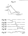
- An example of the gain and phase characteristics of the equalizing circuit is illustrated in Fig. 4 as servo open loop characteristics.
- the compensation operation of the equalizer is such that the gain at the low frequency range is boosted by an integration coefficient so as to improve the traceability of the pickup against the eccentricity of the disc.
- the phase advance is compensated for by means of the differential coefficient.
- the compensation operation is attained primarily by the integration component.
- the tracking error signal after passing through the equalizing circuit effects an acceleration operation to the actuator during a first half period of a track tack jump operation shown as a period A in Fig. 2B, and a deceleration operation to the actuator during a last half period of the track jump operation shown as a period B in Fig. 2B.
- An object of the present invention is therefore to provide a tracking servo system in which the lock in of the servo loop is stably and certainly performed at the time of the track jump operation.
- the equalizing characteristic of the equalizer is changed for a predetermined time period after the closure of the servo loop during a track jump operation. More particularly, in an embodiment of the present invention, the integration and differential coefficients which determine the chatacteristic of the equalizer for compensating the frequency characteristic of the tracking error signal are made variable, and the integration coefficient is made small and the differential coefficient is made large for a predetermined time period after the closing of the servo loop during the track jump operation.
- Fig. l is a block diagram showing an embodiment of the tracking servo system according to the present invention.
- three light spots obtained by converging a laser beam i.e. a light spot Sl for reading information and a pair of light spots S2 and S3 for sensing tracking information, which are preceding and following the light spot Sl respectively while a relative movement between the light spots and the disc occurs, are irradiated from a pickup (not shown) against a recording track T of the disc in such a manner as shown in Fig. l.
- the refelection of these light spots are received by photoelectric converting units l, 2 and 3 incorporated in the pickup.
- the photoelectric converting unit l is of a quadrant form which consists of four independent light receiving elements bounded by two boundary lines crossing sustantially at right angles with each other in the light receiving surface. A summation of output signals of these four light receiving elements forms a playback RF (Radio Frequency) signal.
- a pair of output signals of the photo electric converting units 2 and 3 are supplied to a differential amplifier 4 in which a signal (S2-S3) indicative of a difference between the output signals of the photoelectric converting units 2 and 3 is generated, and the signal (S2-S3) forms the tracking error signal.
- the tracking error signal (S2-S3) will have a sinusoidal waveform as shown in Fig. 2B.
- the level of the tracking signal (S2-S3) becomes proportional to the deviation of the position of the light spot Sl for reading the information from the recording track T, and zero-crossing points of the tracking error signal(S2-S3) correspond to a position of each recording track T (Tl or T2) and a position between the recording tracks Tl and T2.
- the tracking error signal is supplied to an error amplifier 5 in which it is amplified and in turn supplied to an A/D (Analog to Digital) converter 6, a zero-crossing detection circuit 7 and a peak detection circuit 8.
- A/D converter 6 the tracking error signal is converted into digital form, and supplied to a digital equalizer 9in which its frequency characteristic is compensated for, and supplied to a D/A (digital to Analog) converter l0 in which the tracking error signal in digital form is converted into analog form once more, and in turn supplied to a close contact lla of a loop switch ll.
- An output signal of the loop switch is supplied to an actuator l3 of the pickup through a drive circuit l2.
- the actuator l3 is operative to deflect the light spot Sl in the radial direction of the disc so that the light spot Sl for reading information accurately traces the recording track T.
- the tracking servo loop is formed by the above described elements.
- the switching operation of the loop switch ll is controlled by means of a switch control circuit l4, and the servo loop closes when a movable contact of the loop switch ll is positioned at the close contact lla.
- a switch control circuit l4 Under the open loop condition in which the movable contact of the loop switch ll is positioned at an open contact llb, jump pulses of negative polarity for example and brake pulses of positive polarity for example are generated by a pulse generating circuit l5 at suitable intervals and supplied to the actuator l3.
- the track jump operation is performed in this way.
- the intervals or timings of the generation of jump pulses and brake pulses are controllted by a controller l6.
- the zero-crossing detection circuit 7 detects the zero-crossing at the transition of the tracking error signal from positive to negative polarity, and supplies a detection output signal to the controller l6.
- the peak detection circuit 8 detects a state in which the tracking error signal has attained a negative peak level, and supplies a detection output signal to the controller l6.
- the controller l6 omprises a microprocessor and peripheral elements.
- the controller l6 supplies a change-over timing signal for the loop switch ll to the switch control circuit l4, and timing signals for the generation of the jump pulses and the brake pulses to the pulse generating circuit l5 in accordance with a jump command signal from the outside (such as a control part of the disc playing system) and the detection output signals of the zero-crossing detection circuit 7 and the peak detection circuit 8.
- the digital equalizer 9 effects compensation operations corresponding to proportional (P), integral (I), and differential (D) components of an input signal waveform.
- Fig. 3 shows an example of the construction of this digital equalizer 9, which is known in the art.
- K P , K I , K D , and K O represent the proportional coefficient, the integration coefficient, differentiation coefficient, and the incomplete integration coeeficient respectively.
- Z ⁇ 1 represents a previous sampling value.
- Fig. 4 shows an open loop characteristic of the tracking servo system.
- the differential coefficient K D bears the compensation operation of the phase advance in the high frequency range.
- the integration coefficient K I bears the compensation operation of of the gain boost in the low frequency range.
- This digital equalizer 9 is constructed so that both of the integration coefficient K I and the differential coefficient K D determining the equalizing characteristic are variable between two values. More specifically, the integration coefficient K I and the differential coeffocient K D respectively have two values of K I1 and K D1 by which the integration component plays a primary control part, and K I2 ( ⁇ K I1 ) and K D2 (> K D1 ) by which the differential component plays the primary control part.
- a K I , K D control circuit l7 is operated to select the coefficient values K I1 and K D1 during the normal operation, and the coefficient values K I2 and K D2 during a predetermined time period (described later) at the time of a track jump operation.
- the controller l6 When the jump command is supplied to the contorller l6 from the outside, the controller l6 operates the switch control circuit l4 to change over the switch position of the loop switch ll to the open contact llb, and supplies a command to the pulse generating circuit l5 so that it generates a negative jump pulse (Fig. 5A).
- Fig. 5A the pulse generating circuit l5 so that it generates a negative jump pulse
- the signal level of the tracking error signal varies, as shown in Fig. 2B, in the form of a sinusoidal wave in accordance with the movement of the information reading spot Sl with respect to the recording track T.
- the zero-crossing detection circuit 7 generates an output signal (Fig. 5B) having the high level immediately after the extinction of the jump pulse (Fig. 5A), and a transition of the output signal (Fig. 5B) from the high level to the low level occurs when the zero-crossing of the tracking error signal occurs.
- the timing of the transition of the output signal (Fig. 5B) represents the timing of the detection of the zero-crossing.
- the controller supplies a command to the pulse generation circuit l5 so that it generates a positive brake pulse (Fig. 5C).
- This brake pulse (Fig. 5C) is supplied to the acturator l3, to slow down the speed of the movement of the information reading point Sl.
- the peak detection circuit 8 generates an output signal (Fig. 5D) of the high level immediately after the extinction of the brake pulse (Fig. 5C), and a transition of the output signal (Fig. 5D) of the peak detection circuit 8 from the high level to the low level occurs when the negative peak of the tracking error signal is detected by the peak detection circuit 8.
- the timing of this transition of the output signal (Fig. 5D) of the peak detection circuit 8 represents the timing of the detection of the peak.
- the controller l6 operates the switch control circuit ll to switch over the loop switch ll to the close contact lla.
- the controller l6 supplies a swich-over control signal (Fig. 5E) to the K I , K D control circuit l7, so that the integration and differential coefficients K I and K D of the digital equalizer 9 are switched from values K I1 and K D1 to values K I2 and K D2 .
- the equalizer 9 will have the integration coefficient K I smaller than that in the normal playback operation and the differential coefficient K D larger than that in the normal playback operation.
- the differential component plays the primary part of the compensation characteristic under this condition.
- the waveform of the signal supplied to the actuator l3 is shown in Fig. 5F.
- the actuator is supplied with the tracking error signal at first.
- the jump pulse of the negative porality and having a predetermined duration is supplied to the actuator.
- the brake pulse of the positive polarity is supplied to the actuator when the zero-crossing of the tracking error signal is detected.
- the tracking error signal is again supplied to the actuator l3 and the equaliziing characteristic of the digital equalizer 9 is changed when the negative peak of the tracking error signal signal detected by the peak detector 8.
- T a in which the equalizing characteristic is changed from a normal characteristic the lock in of the servo loop occurs.
- the tracking error signal after passing through the equalizer 9 causes the deceleration operation against the actuator l3 during periods C and E shown in Fig. 2B, and causes the acceleration operation against the actuator l3 during a period D shown in Fig. 2B. Therefore, by switching the integration and differential coefficients K I and K D of the equalizer 9 to the values K I2 and K D2 by which the differential component plays a primary part of the compensation operation at the timing of the detection of the peak value, the lock in of the servo loop will take place while the deceleration force is working on the actuator l3.
- the stability of the lock in of the servo loop is increased.
- the gain boost effect for the low frequency range is reduced since the integration coefficient K I is made small.
- the loop gain in the low frequency range is reduced as compared with the normal period as illustrated by the dashed line in Fig. 4.
- the reduction in the gain in the low frequency range has practically no effect on the operation of the system.
- the solid line illustrates the characteristic in the normal playback period.
- the system is constructed such that the integration coefficient of the equalizer is made smaller and the differential coefficient of the equalizer is made larger during a predetermined time period after the closing of the servo loop at a track jump operation, as compared with the normal playback period.
- the servo loop can be locked in when the decelerating force is exerted on the actuator. In this way, the lock in of the servo loop in the track jump operation is attained in the stable and certain manner.
Abstract
Description
- The present invention relates to a tracking servo system for une in an information recording disc playing system.
- A tracking servo system is indispensable in a system for playing an information recording disc such as a video disc or a digital audio disc (hereinafter, simply referred to as a disc) in order to control the position of the information reading light spot so that it always accurately traces a recording track formed on the disc even if the disc is slightly eccentric.
- The tracking servo system forms the so called closed loop control system in which a tracking error signal corresponding to an amount of deviation of the information reading light spot with respect to the recording track of the disc is generated and an actuator for deflecting the information reading spot in a radial direction of the disc is driven in accordance with the tracking error signal, thereby to control the position of the information reading light spot with respect to the recording track.
- Furthermore, in such a servo system, during a track jump operation in which the information reading point is moved across the tracks the control operation is performed such that the servo loop is opened and jump pulses are applied to the tracking actuator, and subsequently the servo loop is closed at a suitable timing, so that the servo loop is locked in quickly.
- In such a tracking servo system, an equalizing circuit capable of a proportional integral differential (PID) operation is incorporated in the servo loop, and the stabilization of the servo loop is attained by the operation of the equalizing circuit. An example of the gain and phase characteristics of the equalizing circuit is illustrated in Fig. 4 as servo open loop characteristics. As shown, the compensation operation of the equalizer is such that the gain at the low frequency range is boosted by an integration coefficient so as to improve the traceability of the pickup against the eccentricity of the disc. Furthermore, the phase advance is compensated for by means of the differential coefficient. However, the compensation operation is attained primarily by the integration component.
- With this type of control system in which the integration component is principal, if it is assumed that the light spot Sl for reading information is moved while the tracking servo loop is closed, the tracking error signal after passing through the equalizing circuit effects an acceleration operation to the actuator during a first half period of a track tack jump operation shown as a period A in Fig. 2B, and a deceleration operation to the actuator during a last half period of the track jump operation shown as a period B in Fig. 2B. This results in that the lock in of the servo loop is performed during the acceleration drive of the actuator. However, this will cause a large overshoot, and the lock in of the servo system will become unstable.
- An object of the present invention is therefore to provide a tracking servo system in which the lock in of the servo loop is stably and certainly performed at the time of the track jump operation.
- In the tracking servo system according to the present invention, the equalizing characteristic of the equalizer is changed for a predetermined time period after the closure of the servo loop during a track jump operation. More particularly, in an embodiment of the present invention, the integration and differential coefficients which determine the chatacteristic of the equalizer for compensating the frequency characteristic of the tracking error signal are made variable, and the integration coefficient is made small and the differential coefficient is made large for a predetermined time period after the closing of the servo loop during the track jump operation.
-
- Fig. l is a block diagram showing an embodiment of the tracking servo system according to the present invention;
- Figs. 2A and 2B are diagrams showing the relationship between the position of the light spot for reading the information and the tracking error signal;
- Fig. 3 is a block diagram showing an example of the construction of the digital equalizer incorporated in the system shown in Fig. l;
- Fig. 4 is a diagram showing an open loop characteristic of the tracking servo system; and
- Figs. 5A through 5F are timing charts illustrating the waveforms of signals at various point in the tracking servo system shown in Fig. l
- Fig. l is a block diagram showing an embodiment of the tracking servo system according to the present invention.
- As shown, three light spots obtained by converging a laser beam, i.e. a light spot Sl for reading information and a pair of light spots S2 and S3 for sensing tracking information, which are preceding and following the light spot Sl respectively while a relative movement between the light spots and the disc occurs, are irradiated from a pickup (not shown) against a recording track T of the disc in such a manner as shown in Fig. l. The refelection of these light spots are received by photoelectric converting units l, 2 and 3 incorporated in the pickup.
- The photoelectric converting unit l is of a quadrant form which consists of four independent light receiving elements bounded by two boundary lines crossing sustantially at right angles with each other in the light receiving surface. A summation of output signals of these four light receiving elements forms a playback RF (Radio Frequency) signal. On the other hand, a pair of output signals of the photo
electric converting units differential amplifier 4 in which a signal (S2-S3) indicative of a difference between the output signals of thephotoelectric converting units - The tracking error signal is supplied to an
error amplifier 5 in which it is amplified and in turn supplied to an A/D (Analog to Digital)converter 6, a zero-crossing detection circuit 7 and apeak detection circuit 8. At the A/D converter 6, the tracking error signal is converted into digital form, and supplied to a digital equalizer 9in which its frequency characteristic is compensated for, and supplied to a D/A (digital to Analog) converter l0 in which the tracking error signal in digital form is converted into analog form once more, and in turn supplied to a close contact lla of a loop switch ll. An output signal of the loop switch is supplied to an actuator l3 of the pickup through a drive circuit l2. The actuator l3 is operative to deflect the light spot Sl in the radial direction of the disc so that the light spot Sl for reading information accurately traces the recording track T. The tracking servo loop is formed by the above described elements. - The switching operation of the loop switch ll is controlled by means of a switch control circuit l4, and the servo loop closes when a movable contact of the loop switch ll is positioned at the close contact lla. Under the open loop condition in which the movable contact of the loop switch ll is positioned at an open contact llb, jump pulses of negative polarity for example and brake pulses of positive polarity for example are generated by a pulse generating circuit l5 at suitable intervals and supplied to the actuator l3. The track jump operation is performed in this way. The intervals or timings of the generation of jump pulses and brake pulses are controllted by a controller l6.
- As shown in Fig. 2B, the zero-
crossing detection circuit 7 detects the zero-crossing at the transition of the tracking error signal from positive to negative polarity, and supplies a detection output signal to the controller l6. On the other hand, thepeak detection circuit 8 detects a state in which the tracking error signal has attained a negative peak level, and supplies a detection output signal to the controller l6. As the zero-crossing detection circuit 7 and thepeak detection circuit 8, commercially available circuits having known circuit construction can be used. The controller l6 omprises a microprocessor and peripheral elements. At the track jump operation, the controller l6 supplies a change-over timing signal for the loop switch ll to the switch control circuit l4, and timing signals for the generation of the jump pulses and the brake pulses to the pulse generating circuit l5 in accordance with a jump command signal from the outside (such as a control part of the disc playing system) and the detection output signals of the zero-crossing detection circuit 7 and thepeak detection circuit 8. - The
digital equalizer 9 effects compensation operations corresponding to proportional (P), integral (I), and differential (D) components of an input signal waveform. - Fig. 3 shows an example of the construction of this
digital equalizer 9, which is known in the art. In Fig. 3, KP, KI, KD, and KO represent the proportional coefficient, the integration coefficient, differentiation coefficient, and the incomplete integration coeeficient respectively. Z⁻¹ represents a previous sampling value. - If the input signal, the output signal, and the equalizing characteristic are expressed by X(z), Y(z), and EQ(z) respectively, the relation between the input signal and the output signal can be expressed by:
Y(Z) = EQ (Z)· X(Z)
where EQ (Z) is further expressed by the following equation:
EQ(Z) = KP + KD· (l-Z⁻¹) + KI/(l-KO· Z⁻¹)
- Fig. 4 shows an open loop characteristic of the tracking servo system. In this characteristic, the differential coefficient KD bears the compensation operation of the phase advance in the high frequency range. On the other hand, the integration coefficient KI bears the compensation operation of of the gain boost in the low frequency range.
- This
digital equalizer 9 is constructed so that both of the integration coefficient KI and the differential coefficient KD determining the equalizing characteristic are variable between two values. More specifically, the integration coefficient KI and the differential coeffocient KD respectively have two values of KI1 and KD1 by which the integration component plays a primary control part, and KI2 (< KI1) and KD2 (> KD1) by which the differential component plays the primary control part. In accordance with a command from the controller l6, a KI, KD control circuit l7 is operated to select the coefficient values KI1 and KD1 during the normal operation, and the coefficient values KI2 and KD2 during a predetermined time period (described later) at the time of a track jump operation. - The operation of the circuit constructed as described above, at the time of the track jump operation will be described with reference to timing charts of Figs. 5A through 5F hereinafter.
- When the jump command is supplied to the contorller l6 from the outside, the controller l6 operates the switch control circuit l4 to change over the switch position of the loop switch ll to the open contact llb, and supplies a command to the pulse generating circuit l5 so that it generates a negative jump pulse (Fig. 5A). By this operation, as shown in Fig. 2A, the information reading spot Sl moves from the track Tl toward the track T2. While this movement of the information reading point occurs, the signal level of the tracking error signal varies, as shown in Fig. 2B, in the form of a sinusoidal wave in accordance with the movement of the information reading spot Sl with respect to the recording track T.
- The zero-crossing
detection circuit 7 generates an output signal (Fig. 5B) having the high level immediately after the extinction of the jump pulse (Fig. 5A), and a transition of the output signal (Fig. 5B) from the high level to the low level occurs when the zero-crossing of the tracking error signal occurs. Thus, the timing of the transition of the output signal (Fig. 5B) represents the timing of the detection of the zero-crossing. In response to the transition of the output signal (Fig. 5B) of the zero-crossingdetection circuit 7 which represents the timing of the detection of the zero-crossing, the controller supplies a command to the pulse generation circuit l5 so that it generates a positive brake pulse (Fig. 5C). This brake pulse (Fig. 5C) is supplied to the acturator l3, to slow down the speed of the movement of the information reading point Sl. - The
peak detection circuit 8 generates an output signal (Fig. 5D) of the high level immediately after the extinction of the brake pulse (Fig. 5C), and a transition of the output signal (Fig. 5D) of thepeak detection circuit 8 from the high level to the low level occurs when the negative peak of the tracking error signal is detected by thepeak detection circuit 8. The timing of this transition of the output signal (Fig. 5D) of thepeak detection circuit 8 represents the timing of the detection of the peak. In response to the transition of the output signal (Fig. 5D) of thepeak detection circuit 8 representing the detection of the peak, the controller l6 operates the switch control circuit ll to switch over the loop switch ll to the close contact lla. Moreover, a predetermined time period Ta from this time point, the controller l6 supplies a swich-over control signal (Fig. 5E) to the KI, KD control circuit l7, so that the integration and differential coefficients KI and KD of thedigital equalizer 9 are switched from values KI1 and KD1to values KI2 and KD2. By this operation, theequalizer 9 will have the integration coefficient KI smaller than that in the normal playback operation and the differential coefficient KD larger than that in the normal playback operation. Thus, the differential component plays the primary part of the compensation characteristic under this condition. - The waveform of the signal supplied to the actuator l3 is shown in Fig. 5F. As shown, the actuator is supplied with the tracking error signal at first. When a jump command is supplied to the controller, the jump pulse of the negative porality and having a predetermined duration is supplied to the actuator. Subsequently, the brake pulse of the positive polarity is supplied to the actuator when the zero-crossing of the tracking error signal is detected. After the extinction of the brake pulse, the tracking error signal is again supplied to the actuator l3 and the equaliziing characteristic of the
digital equalizer 9 is changed when the negative peak of the tracking error signal signal detected by thepeak detector 8. Within the time period Ta in which the equalizing characteristic is changed from a normal characteristic, the lock in of the servo loop occurs. - In the control system in which the differential component is principal as in the state explained above, if it is assumed that the light spot Sl for reading information is moved while the tracking servo loop is closed, the tracking error signal after passing through the
equalizer 9 causes the deceleration operation against the actuator l3 during periods C and E shown in Fig. 2B, and causes the acceleration operation against the actuator l3 during a period D shown in Fig. 2B. Therefore, by switching the integration and differential coefficients KI and KD of theequalizer 9 to the values KI2 and KD2 by which the differential component plays a primary part of the compensation operation at the timing of the detection of the peak value, the lock in of the servo loop will take place while the deceleration force is working on the actuator l3. Thus, the stability of the lock in of the servo loop is increased. Under this condition, the gain boost effect for the low frequency range is reduced since the integration coefficient KI is made small. This means that the loop gain in the low frequency range is reduced as compared with the normal period as illustrated by the dashed line in Fig. 4. However, since the time required for the lock in of the servo loop is relatively short, the reduction in the gain in the low frequency range has practically no effect on the operation of the system. In Fig. 4, the solid line illustrates the characteristic in the normal playback period. - When the aforementioned predetermiend time period has elapsed, the integration and differential coefficients KI and KD of the digital equalizer are reverted to the values KI1 and KD1 respectively, so that the control operation in which the integration component plays the primary part. Thus, the traceability of the pickup against the eccentricity of the disc is assured.
- It will be appreciated from the foregoing, according to the present invention, the system is constructed such that the integration coefficient of the equalizer is made smaller and the differential coefficient of the equalizer is made larger during a predetermined time period after the closing of the servo loop at a track jump operation, as compared with the normal playback period. Thus, the servo loop can be locked in when the decelerating force is exerted on the actuator. In this way, the lock in of the servo loop in the track jump operation is attained in the stable and certain manner.
Claims (4)
tracking error signal generating means for generating a tracking error signal in accordance with an amount of shift of an information reading spot of said pickup with respect to a recording track formed on said disc, in a radial direction of said disc;
drive means for deflecting said information reading spot in said radial direction of said disc;
equalizing means connected to said tracking error signal generating means for compensating a frequency characteristic of said tracking error signal and producing an output signal;
loop switch disposed between said equalizing means and said drive means for switching the transmission of said output signal of said equalizing means to said drive means; and
control means for stopping the transmission of said output signal of said equalizing means to said drive means in response to a jump command for a track jump operation by which said information reading spot moves from a recording track section to another recording track section, and for resuming the transmission of said output signal of said equalizing means to close a servo loop at a desirable timing during said track jump operation, wherein said control means is further operative to change an equalizing characteristic of said equalizing means for a predetermined time period after the resumption of the transmission of said output signal of said equalizing means to close said servo loop.
Applications Claiming Priority (2)
| Application Number | Priority Date | Filing Date | Title |
|---|---|---|---|
| JP61131551A JPH0679420B2 (en) | 1986-06-06 | 1986-06-06 | Tracking servo device |
| JP131551/86 | 1986-06-06 |
Publications (4)
| Publication Number | Publication Date |
|---|---|
| EP0248444A2 true EP0248444A2 (en) | 1987-12-09 |
| EP0248444A3 EP0248444A3 (en) | 1989-07-26 |
| EP0248444B1 EP0248444B1 (en) | 1993-02-10 |
| EP0248444B2 EP0248444B2 (en) | 1998-07-29 |
Family
ID=15060719
Family Applications (1)
| Application Number | Title | Priority Date | Filing Date |
|---|---|---|---|
| EP87108179A Expired - Lifetime EP0248444B2 (en) | 1986-06-06 | 1987-06-05 | Tracking servo system for an information recording disc player |
Country Status (4)
| Country | Link |
|---|---|
| US (1) | US4817073A (en) |
| EP (1) | EP0248444B2 (en) |
| JP (1) | JPH0679420B2 (en) |
| DE (1) | DE3784100T3 (en) |
Cited By (3)
| Publication number | Priority date | Publication date | Assignee | Title |
|---|---|---|---|---|
| EP0359368A1 (en) * | 1988-09-13 | 1990-03-21 | Pioneer Electronic Corporation | Tracking servo system |
| EP0364085A2 (en) * | 1988-10-11 | 1990-04-18 | Pioneer Electronic Corporation | Tracking servo apparatus |
| EP0471917A2 (en) * | 1990-07-20 | 1992-02-26 | Pioneer Electronic Corporation | Tracking servo system |
Families Citing this family (25)
| Publication number | Priority date | Publication date | Assignee | Title |
|---|---|---|---|---|
| US5184338A (en) * | 1987-06-25 | 1993-02-02 | Mitsubishi Denki Kabushiki Kaisha | Optical disc system with improved track jumping operation |
| JPS648563A (en) * | 1987-06-30 | 1989-01-12 | Toshiba Corp | Track counter |
| JPS6460879A (en) * | 1987-09-01 | 1989-03-07 | Pioneer Electronic Corp | Scanning method in disk player |
| DE3732916A1 (en) * | 1987-09-30 | 1989-04-20 | Thomson Brandt Gmbh | DEVICE FOR PLAYING BACK DATA |
| JP2546882B2 (en) * | 1988-09-16 | 1996-10-23 | パイオニア株式会社 | Tracking servo device |
| JPH0782721B2 (en) * | 1988-10-05 | 1995-09-06 | パイオニア株式会社 | Servo device for disc player |
| JP2646130B2 (en) * | 1989-03-13 | 1997-08-25 | パイオニア株式会社 | Track jump drive |
| JP2745665B2 (en) * | 1989-04-14 | 1998-04-28 | ソニー株式会社 | Detrack detection method for optical recording / reproducing device |
| JP2836756B2 (en) * | 1990-04-19 | 1998-12-14 | オリンパス光学工業株式会社 | Track jump control device for optical information recording / reproducing device |
| JP2931042B2 (en) * | 1990-05-28 | 1999-08-09 | パイオニア株式会社 | Optical disc playback device |
| JPH0460974A (en) * | 1990-06-26 | 1992-02-26 | Pioneer Electron Corp | Tracking servo device |
| KR100272118B1 (en) * | 1991-11-06 | 2000-11-15 | 이데이 노부유끼 | Optical disk player and tracking servo circuit with digital servo control circuit |
| JPH05307848A (en) * | 1992-05-01 | 1993-11-19 | Ricoh Co Ltd | Closed loop system and servo device for optical disk device |
| JPH0652556A (en) * | 1992-07-29 | 1994-02-25 | Mitsumi Electric Co Ltd | Pickup driving system of optical disk device |
| JPH06162544A (en) * | 1992-11-13 | 1994-06-10 | Sony Corp | Tracking servo circuit |
| JPH07129973A (en) * | 1993-10-29 | 1995-05-19 | Pioneer Electron Corp | Tracking device of sampled servo system |
| US5446716A (en) * | 1994-01-10 | 1995-08-29 | Eastman Kodak Company | Laser power control in an optical recording system to compensate for multiple system degradations |
| JPH0814868A (en) * | 1994-06-27 | 1996-01-19 | Sony Corp | Device for inspecting outer surface of disc-like recording medium |
| US6741416B2 (en) * | 1999-12-16 | 2004-05-25 | Matsushita Electric Industrial Co., Ltd. | Tracking signal generating device and method, and magnetic recording/reproducing system |
| JP2001307346A (en) * | 2000-04-24 | 2001-11-02 | Pioneer Electronic Corp | Servo controller of optical disk player |
| JP4543244B2 (en) * | 2001-02-20 | 2010-09-15 | 船井電機株式会社 | Track jump control device and track jump method |
| KR100878524B1 (en) * | 2002-05-21 | 2009-01-13 | 삼성전자주식회사 | Apparatus and method for updating filter tap coefficients of an equalizer |
| TWI257621B (en) * | 2003-09-30 | 2006-07-01 | Mediatek Inc | Track locking method and apparatus for optical disk device |
| JP2005203057A (en) * | 2004-01-19 | 2005-07-28 | Funai Electric Co Ltd | Recording reproducing device for optical disc |
| JPWO2005083883A1 (en) * | 2004-03-02 | 2007-11-29 | ローム株式会社 | Waveform equalizer and information reproducing apparatus having the same |
Citations (7)
| Publication number | Priority date | Publication date | Assignee | Title |
|---|---|---|---|---|
| US4332022A (en) * | 1978-03-27 | 1982-05-25 | Discovision Associates | Tracking system and method for video disc player |
| JPS59152567A (en) * | 1983-02-21 | 1984-08-31 | Toshiba Corp | Disk record reproducer |
| JPS60258775A (en) * | 1984-06-06 | 1985-12-20 | Toshiba Corp | Tracking control circuit of disc reproducing device |
| JPS618740A (en) * | 1984-06-20 | 1986-01-16 | Fujitsu Ltd | Track jump control circuit |
| JPS6129424A (en) * | 1984-06-15 | 1986-02-10 | Olympus Optical Co Ltd | Optical information recording and reproducing device |
| JPS6180529A (en) * | 1984-09-26 | 1986-04-24 | Fujitsu Ltd | Track servo system |
| JPS61133046A (en) * | 1984-12-03 | 1986-06-20 | Fujitsu General Ltd | Tracking servo circuit |
Family Cites Families (4)
| Publication number | Priority date | Publication date | Assignee | Title |
|---|---|---|---|---|
| JPS592240A (en) * | 1982-06-25 | 1984-01-07 | Pioneer Electronic Corp | Tracking servo device |
| US4677602A (en) * | 1983-04-05 | 1987-06-30 | Pioneer Electronic Corporation | Device for controlling recording track jump operations with over-run correction |
| JPS6045984A (en) * | 1983-08-22 | 1985-03-12 | Sony Corp | Optical recording/reproducing device |
| JPS61977A (en) * | 1984-06-13 | 1986-01-06 | Pioneer Electronic Corp | Tracking servo device |
-
1986
- 1986-06-06 JP JP61131551A patent/JPH0679420B2/en not_active Expired - Fee Related
-
1987
- 1987-06-04 US US07/058,144 patent/US4817073A/en not_active Expired - Lifetime
- 1987-06-05 DE DE3784100T patent/DE3784100T3/en not_active Expired - Fee Related
- 1987-06-05 EP EP87108179A patent/EP0248444B2/en not_active Expired - Lifetime
Patent Citations (7)
| Publication number | Priority date | Publication date | Assignee | Title |
|---|---|---|---|---|
| US4332022A (en) * | 1978-03-27 | 1982-05-25 | Discovision Associates | Tracking system and method for video disc player |
| JPS59152567A (en) * | 1983-02-21 | 1984-08-31 | Toshiba Corp | Disk record reproducer |
| JPS60258775A (en) * | 1984-06-06 | 1985-12-20 | Toshiba Corp | Tracking control circuit of disc reproducing device |
| JPS6129424A (en) * | 1984-06-15 | 1986-02-10 | Olympus Optical Co Ltd | Optical information recording and reproducing device |
| JPS618740A (en) * | 1984-06-20 | 1986-01-16 | Fujitsu Ltd | Track jump control circuit |
| JPS6180529A (en) * | 1984-09-26 | 1986-04-24 | Fujitsu Ltd | Track servo system |
| JPS61133046A (en) * | 1984-12-03 | 1986-06-20 | Fujitsu General Ltd | Tracking servo circuit |
Non-Patent Citations (7)
| Title |
|---|
| PATENT ABSTRACTS OF JAPAN, vol. 10, no. 140 (P-458)[2197] 23 May 1986; & JP-A-60 258 775 (TOSHIBA K.K.) * |
| PATENT ABSTRACTS OF JAPAN, vol. 10, no. 154, (P-463)[2210] 04 June 1986; & JP-A-61 008 740 (FUJITSU K.K.) * |
| PATENT ABSTRACTS OF JAPAN, vol. 10, no. 327 (P-513)[2383] 07 November 1986; & JP-A-61 133 046 (FUJITSU GENERAL LTD) * |
| PATENT ABSTRACTS OF JAPAN, vol. 9, no. 2 (P-325)[1725] 08 January 1985; & JP-A-59 152 567 (TOSHIBA K.K.) * |
| PATENT ABSTRACTS OF JAPAN, Vol.10, no. 180, (P-471)[2236] June 24, 1986; & JP-A-61 029 424 (OLYMPUS OPTICAL CO LTD) * |
| PATENT ABSTRACTS OF JAPAN, Vol.10, no. 254, (P-492)[2310] August 30, 1986; & JP-A-61 080 529 (FUJITSU LTD.) * |
| RESEARCH DISCLOSURE, no. 248, December 1984, Emsworth, Hampshire, Great-Britain; page 588 - 589; Art. Nr. 24809: "Single Track Step" * |
Cited By (5)
| Publication number | Priority date | Publication date | Assignee | Title |
|---|---|---|---|---|
| EP0359368A1 (en) * | 1988-09-13 | 1990-03-21 | Pioneer Electronic Corporation | Tracking servo system |
| EP0364085A2 (en) * | 1988-10-11 | 1990-04-18 | Pioneer Electronic Corporation | Tracking servo apparatus |
| EP0364085A3 (en) * | 1988-10-11 | 1990-06-13 | Pioneer Electronic Corporation | Tracking servo apparatus |
| EP0471917A2 (en) * | 1990-07-20 | 1992-02-26 | Pioneer Electronic Corporation | Tracking servo system |
| EP0471917A3 (en) * | 1990-07-20 | 1992-10-21 | Pioneer Electronic Corporation | Tracking servo system |
Also Published As
| Publication number | Publication date |
|---|---|
| EP0248444B2 (en) | 1998-07-29 |
| US4817073A (en) | 1989-03-28 |
| DE3784100T2 (en) | 1993-05-27 |
| JPS62287485A (en) | 1987-12-14 |
| DE3784100D1 (en) | 1993-03-25 |
| DE3784100T3 (en) | 1998-10-29 |
| JPH0679420B2 (en) | 1994-10-05 |
| EP0248444A3 (en) | 1989-07-26 |
| EP0248444B1 (en) | 1993-02-10 |
Similar Documents
| Publication | Publication Date | Title |
|---|---|---|
| US4817073A (en) | Tracking servo system for an information recording disc player | |
| US4835752A (en) | Device for driving and controlling optical head for use in optical disk system | |
| US4613963A (en) | Tracking-servo device | |
| JP2009004095A (en) | Optical disk drive storage system, method for controlling movement of optical lead head, and sliding mode controller | |
| US4786849A (en) | Offset compensating circuit in fine control servo device | |
| EP0359368B1 (en) | Tracking servo system | |
| US4698795A (en) | Tracking servo device | |
| EP0464986B1 (en) | Tracking servo apparatus | |
| JPS63131332A (en) | Tracking controller for optical pickup | |
| US5148425A (en) | Overshoot minimizing tracking servo apparatus | |
| JP2661291B2 (en) | Focus control retractor | |
| JPH0682470B2 (en) | Information recording medium track position control device for recording device | |
| JPH09167357A (en) | Track jump controller for optical recording and reproducing device | |
| JP2718053B2 (en) | Focus servo gain adjustment device | |
| JPS62277629A (en) | Tracking servo pull-in method | |
| US6345019B1 (en) | Disk drive system with releasing apparatus | |
| KR950024161A (en) | Tracking pull-in method and apparatus in optical disk system | |
| JPH03209633A (en) | Method and device for leading focus control | |
| US20030133370A1 (en) | Method and reproducing apparatus for performing an actuator jump operation | |
| JP2596013B2 (en) | Optical disk recording and playback device | |
| JPH0237579A (en) | Access speed detector for optical recording and/or reproducing device | |
| JPH0294081A (en) | Servo device for disk player | |
| JPH05166203A (en) | Automatic gain adjusting device for servo error signal | |
| JPH0434775A (en) | Track jump controller for information recording and reproducing device | |
| JPH0540525A (en) | Digital servo device |
Legal Events
| Date | Code | Title | Description |
|---|---|---|---|
| PUAI | Public reference made under article 153(3) epc to a published international application that has entered the european phase |
Free format text: ORIGINAL CODE: 0009012 |
|
| AK | Designated contracting states |
Kind code of ref document: A2 Designated state(s): DE FR GB NL |
|
| PUAL | Search report despatched |
Free format text: ORIGINAL CODE: 0009013 |
|
| AK | Designated contracting states |
Kind code of ref document: A3 Designated state(s): DE FR GB NL |
|
| 17P | Request for examination filed |
Effective date: 19890908 |
|
| 17Q | First examination report despatched |
Effective date: 19910212 |
|
| GRAA | (expected) grant |
Free format text: ORIGINAL CODE: 0009210 |
|
| AK | Designated contracting states |
Kind code of ref document: B1 Designated state(s): DE FR GB NL |
|
| REF | Corresponds to: |
Ref document number: 3784100 Country of ref document: DE Date of ref document: 19930325 |
|
| ET | Fr: translation filed | ||
| PLBI | Opposition filed |
Free format text: ORIGINAL CODE: 0009260 |
|
| 26 | Opposition filed |
Opponent name: INTERESSENGEMEINSCHAFT FUER RUNDFUNKSCHUTZRECHTE E Effective date: 19931110 |
|
| NLR1 | Nl: opposition has been filed with the epo |
Opponent name: INTERESSENGEMEINSCHAFT FUER RUNDFUNKSCHUTZRECHTE E |
|
| REG | Reference to a national code |
Ref country code: GB Ref legal event code: 746 Effective date: 19950509 |
|
| PLAB | Opposition data, opponent's data or that of the opponent's representative modified |
Free format text: ORIGINAL CODE: 0009299OPPO |
|
| R26 | Opposition filed (corrected) |
Opponent name: INTERESSENGEMEINSCHAFT FUER RUNDFUNKSCHUTZRECHTE E Effective date: 19931110 |
|
| REG | Reference to a national code |
Ref country code: FR Ref legal event code: D6 |
|
| NLR1 | Nl: opposition has been filed with the epo |
Opponent name: INTERESSENGEMEINSCHAFT FUER RUNDFUNKSCHUTZRECHTE E |
|
| APAC | Appeal dossier modified |
Free format text: ORIGINAL CODE: EPIDOS NOAPO |
|
| PLAW | Interlocutory decision in opposition |
Free format text: ORIGINAL CODE: EPIDOS IDOP |
|
| PUAH | Patent maintained in amended form |
Free format text: ORIGINAL CODE: 0009272 |
|
| STAA | Information on the status of an ep patent application or granted ep patent |
Free format text: STATUS: PATENT MAINTAINED AS AMENDED |
|
| 27A | Patent maintained in amended form |
Effective date: 19980729 |
|
| AK | Designated contracting states |
Kind code of ref document: B2 Designated state(s): DE FR GB NL |
|
| NLR2 | Nl: decision of opposition | ||
| NLR3 | Nl: receipt of modified translations in the netherlands language after an opposition procedure | ||
| ET3 | Fr: translation filed ** decision concerning opposition | ||
| REG | Reference to a national code |
Ref country code: GB Ref legal event code: IF02 |
|
| PGFP | Annual fee paid to national office [announced via postgrant information from national office to epo] |
Ref country code: GB Payment date: 20050601 Year of fee payment: 19 |
|
| PGFP | Annual fee paid to national office [announced via postgrant information from national office to epo] |
Ref country code: DE Payment date: 20050602 Year of fee payment: 19 |
|
| PGFP | Annual fee paid to national office [announced via postgrant information from national office to epo] |
Ref country code: NL Payment date: 20050605 Year of fee payment: 19 |
|
| PGFP | Annual fee paid to national office [announced via postgrant information from national office to epo] |
Ref country code: FR Payment date: 20050608 Year of fee payment: 19 |
|
| APAH | Appeal reference modified |
Free format text: ORIGINAL CODE: EPIDOSCREFNO |
|
| PG25 | Lapsed in a contracting state [announced via postgrant information from national office to epo] |
Ref country code: GB Free format text: LAPSE BECAUSE OF NON-PAYMENT OF DUE FEES Effective date: 20060605 |
|
| PG25 | Lapsed in a contracting state [announced via postgrant information from national office to epo] |
Ref country code: NL Free format text: LAPSE BECAUSE OF NON-PAYMENT OF DUE FEES Effective date: 20070101 |
|
| PG25 | Lapsed in a contracting state [announced via postgrant information from national office to epo] |
Ref country code: DE Free format text: LAPSE BECAUSE OF NON-PAYMENT OF DUE FEES Effective date: 20070103 |
|
| GBPC | Gb: european patent ceased through non-payment of renewal fee |
Effective date: 20060605 |
|
| NLV4 | Nl: lapsed or anulled due to non-payment of the annual fee |
Effective date: 20070101 |
|
| REG | Reference to a national code |
Ref country code: FR Ref legal event code: ST Effective date: 20070228 |
|
| PG25 | Lapsed in a contracting state [announced via postgrant information from national office to epo] |
Ref country code: FR Free format text: LAPSE BECAUSE OF NON-PAYMENT OF DUE FEES Effective date: 20060630 |