EP0248616A2 - Picture printing apparatus - Google Patents
Picture printing apparatus Download PDFInfo
- Publication number
- EP0248616A2 EP0248616A2 EP87304815A EP87304815A EP0248616A2 EP 0248616 A2 EP0248616 A2 EP 0248616A2 EP 87304815 A EP87304815 A EP 87304815A EP 87304815 A EP87304815 A EP 87304815A EP 0248616 A2 EP0248616 A2 EP 0248616A2
- Authority
- EP
- European Patent Office
- Prior art keywords
- dot
- picture
- binary
- multivalence
- printing
- Prior art date
- Legal status (The legal status is an assumption and is not a legal conclusion. Google has not performed a legal analysis and makes no representation as to the accuracy of the status listed.)
- Withdrawn
Links
Images


Classifications
-
- H—ELECTRICITY
- H04—ELECTRIC COMMUNICATION TECHNIQUE
- H04N—PICTORIAL COMMUNICATION, e.g. TELEVISION
- H04N1/00—Scanning, transmission or reproduction of documents or the like, e.g. facsimile transmission; Details thereof
- H04N1/40—Picture signal circuits
- H04N1/403—Discrimination between the two tones in the picture signal of a two-tone original
-
- H—ELECTRICITY
- H04—ELECTRIC COMMUNICATION TECHNIQUE
- H04N—PICTORIAL COMMUNICATION, e.g. TELEVISION
- H04N1/00—Scanning, transmission or reproduction of documents or the like, e.g. facsimile transmission; Details thereof
- H04N1/40—Picture signal circuits
- H04N1/40062—Discrimination between different image types, e.g. two-tone, continuous tone
-
- H—ELECTRICITY
- H04—ELECTRIC COMMUNICATION TECHNIQUE
- H04N—PICTORIAL COMMUNICATION, e.g. TELEVISION
- H04N1/00—Scanning, transmission or reproduction of documents or the like, e.g. facsimile transmission; Details thereof
- H04N1/40—Picture signal circuits
- H04N1/40087—Multi-toning, i.e. converting a continuous-tone signal for reproduction with more than two discrete brightnesses or optical densities, e.g. dots of grey and black inks on white paper
-
- H—ELECTRICITY
- H04—ELECTRIC COMMUNICATION TECHNIQUE
- H04N—PICTORIAL COMMUNICATION, e.g. TELEVISION
- H04N1/00—Scanning, transmission or reproduction of documents or the like, e.g. facsimile transmission; Details thereof
- H04N1/40—Picture signal circuits
- H04N1/405—Halftoning, i.e. converting the picture signal of a continuous-tone original into a corresponding signal showing only two levels
- H04N1/4051—Halftoning, i.e. converting the picture signal of a continuous-tone original into a corresponding signal showing only two levels producing a dispersed dots halftone pattern, the dots having substantially the same size
Definitions
- This invention relates to a picture printing apparatus, and more particularly to a picture printing apparatus wherein the picture is printed based upon the features of an original picture.
- a thermal transfer printing system is a transfer system which transfers the ink of an inkfilm coated with thermal melting or thermal sublimating ink to the printing paper by a thermal head.
- the thermal head is heated by applying power to a thermal resistance element.
- a thermal transfer printing system using the thermal melting ink is suitable particularly for binary images having only "1" and "0" concentration levels.
- concentration modulation technique For multivalence pictures, a special concentration modulation technique is necessary.
- concentration modulation technique a pseudo halftone printing system for expressing the halftone picture has been attempted by modifying dot density or the ink occupation ratio over a constant area. This is a system widely used to display the gradations with a dot printer that has only the - binary concentration expression ability. Typical examples of this method include the dither method, fixed concentration pattern method and multivalence concentration pattern method.
- the concentration level of dots in portions of the original picture are compared with threshold levels corresponding to the location of those portions.
- the dots of a given portion are only printed when the threshold level is exceeded.
- the dither method is a method to make multivalence pictures in a binary way using threshold patterns (shown in Fig.l), and the thermal energy supplied to every dot is the same. Therefore this dither method prints a picture in accordance with a variable : gradation by controlling the number of printing dots and the ink occupation ratio in a given part of the picture.
- dots are printed according to the element pattern shown in Fig.2 based on the dot concentration of the corresponding picture element of the original picture.
- a multivalence concentration pattern method has been developed by the present inventors, as described in U.S. Patent Application S.N.821,954.
- the dither method and the fixed concentration pattern method it is difficult to obtain clear and natural pictures taking into account the visual characteristics of the human being.
- discontinuities of gradation are formed in the medium and high concentration areas , uneveness results from unstable ink adhesion in the low and medium concentration areas,and so on.
- the thermal storage effect of the thermal head that was considered conventionally to be a hindrance in producing good prints, can be positively utilized, and smooth pictures of high quality can be produced with a stabilized gradation .
- This multivalence concentration pattern method utilizes three dot patterns "A",”B”and “C”, corresponding to the low, medium and high concentration levels, respectively, and also corresponding to the energy areas supplied to the thermal head.
- the energy areas are mutually related to the printing concentration.
- the low concentration fixed pattern "A” is an isolated dot pattern formed by isolating one dot in a picture element, and the gradations in the low concentration area are expressed by modulating the printing energy ( energy supplied to the thermal head) and changing the dot size.
- the medium concentration fixed pattern "B” is a stripe shaped pattern extending in the relative transfer direction (subscanning direction) between the thermal head and printing paper, and the gradations in the medium concentration area are expressed by changing the stripe width by the energy supplied to the thermal head.
- the high concentration fixed pattern "C” is an L-shaped pattern combined with a white section of dimension 2 x 2, and the gradations of high concentration are expressed by changing the size of the white section in proportion to the remainding portion of the L-shaped dot pattern.
- Either the multivalence concentration pattern method or the fixed concentration pattern method may be used for good quality printing of multivalence pictures, but if the multivalence pattern method is used for printing binary pictures, poor quality pictures result because the matrix is enlarged. For this reason, mixed multivalence and binary pictures cannot be printed clearly, because the binary portion has such a low resolution.
- a picture printing apparatus for reproducing an original image comprises means for detecting the picture signal from each of a plurality of individual areas on the original image, each area being divided into a plurality of dot segments; means for generating a multivalence concentration pattern including a variable dot value corresponding to each dot segment of the original image in response to the detecting means; means responsive to the detecting means for generating a binary pattern including one of two fixed dot values corresponding to each dot segment of the original image; means for selecting the dot value from one of the binary and multivalence patterns corresponding to each individual dot segment to be printed; and means for printing dots in the dot segments corresponding to the selected dot values in response to the selecting means for reproducing the original image.
- a picture printing apparatus for reproducing an original color image based comprises means for detecting the picture signal from each of a plurality of individual areas on the original image, each area being divided into a plurality of dot segments, including a high resolution sensor and a low resolution sensor; means for generating a multivalence concentration pattern including a variable dot value corresponding to each dot segment of the original image in response to the low resolution sensor; means responsive to the low resolution sensor for generating a binary pattern including one of two fixed dot values corresponding to each dot segment of the original image; means responsive to the high resolution sensor for selecting the dot value from one of the binary and multivalence patterns corresponding to each individual dot segment to be printed; and means for printing dots in the dot segments corresponding to the selected dot values in response to the selecting means.
- the apparatus of the present ivention includes a CPU 1, used to control the whole unit, a print control circuit 15 and a timing circuit 16.
- a picture reader 2 generates picture signals by reading pictures (original pictures) including the halftone portions thereof. Picture signals are converted and output as multivalence digital signals (for example,expressed as 8 bits per picture element).
- a frame memory 3 stores the picture signals generated by the picture reader 2. The frame memory 3_is not required in case the picture read operation and printing output operation are not separated in terms of the time.
- the output of the frame memory 3 is input into a multivalence concentration pattern generation circuit 6 through an averaging circuit 4 and a line memory 5, and signals for multivalence picture printing are generated.
- the averaging circuit 4 is a circuit to carry out the averaging processing of M X M corresponding to M X N dots of the multivalence concentration pattern matrix size on the multivalence picture signal data from the frame memory 5. This averaged data is transferred one line at a time to the line memory 5 (portion of N lines before averaging).
- the multivalence concentration pattern generation circuit 6 generates signals for multivalence picture printing of the multivalence concentration patterns composed of matrices of M X N dots, employing the data in this portion of one line.
- These signals for multivalence picture printing enlarge the pattern size to M times in the main scanning direction, and to N times in the subscanning direction (N lines), respectively, against the multivalence picture signals input into the multivalence concentration pattern generation circuit 6. Therefore, averaged multivalence picture signals are supplied to the line memory 5 from the averaging circuit 4 one line at a time.
- the multivalence concentration pattern generation circuit 6 is controlled by a matrix address generation circuit 7.
- a dither/binary circuit 8 carrys out the dither processing and binary processing for picture signals output from the frame memory 3, and generates dither picture signals and_binary picture signals.
- the output signals of the frame memory 3 are applied to picture type judgement circuit 10 through a filter circuit 9.
- the picture type judgement circuit 10 determines whether the input picture is a multivalence picture or a binary picture. There are cases when this judgement cannot be made, and in such cases, the judgement circuit 10 outputs a different signal corresponding to this condition.
- a multivalence, binary and dither switching circuit 11 switches the printing picture mode on the basis of the judgement result of the picture type judgement circuit 10.
- the judgement result of the judgement circuit 10 indicates a multivalent picture
- signals for multivalence picture recording from the multivalence concentration pattern generation circuit 6 are output.
- the judgement result indcates binary pictures binary picture signals from the dither/binary circuit 8 are output after being individually modulated.
- the judgement result indefinite (no judgement) dither picture signals from the dither/binary circuit 8 are output after being modulated.
- the multivalence, binary and dither switching circuit 11 carries out its switching dot by dot.
- Fig. 6 shows this aspect.
- FIG. 6 (a) shows the data of signals for multivalence picture printing, after conversion to multivalence concentration patterns in the multivalence concentration pattern generation circuit 6, and Fig 6 (b) and Fig 6 (c) show the data of dither pictures and binary pictures obtained in the dither/binary circuit 8, respectively.
- Fig. 6 (d) is an example of the judgement output in the picture type judgement circuit 10.
- "A” shows the judgement result for multivalence pictures, "B” for indefinite (no judgement), and "C” for binary pictures, respectively.
- the multivalence, binary and dither switching circuit 11 switches printing output pictures in accordance with this judgement result, and this switching can be changed as shown in Figs. 6 (e) and (f) whether binary pictures or multivalence concentration pictures are present.
- a binary and dither picture concentration generation circuit 12 generates signals corresponding to the necessary printing energy (supplying energy of the thermal head) so that printed dots are of a proper size.
- the expressions 5 on the pattern shown in Fig. 6 correspond to the printing concentration of binary pictures.
- Signals for multivalence picture printing thus output from the multivalence, binary and dither switching circuit 11 are supplied to a thermal head drive circuit 13.
- the thermal head drive circuit 13 converts the multivalence concentration patterns given by signals for multivalence picture printing to the pulse width of pulses to drive the thermal head in the thermal transfer printer 14.
- the drive circiut 13 also controls the supply of energy to the thermal head.
- the printing control circuit 15 controls the thermal transfer printer 14, and accurately carries out the transport, control, etc. of the ink ribbon, printing paper, etc. by the commands from the CPU 1.
- a timing circuit 16 generates synchronous signals of one line that are required in case the data of picture signals is transferred, and supplies the synchronous signals to the required circuit. For example, the timing circuit may act as a timing clock for data transfer.
- Fig. 7 is a timing chart to show the operation of the present embodiment, and one cycle of dot clock corresponds to the printing time of one dot by the thermal head. Multivalence picture signals are switched once in four cycles of dot clock. In the meantime, the multivalence concentration pattern generation circuit 6 is controlled by the matrix address generation circuit 7, and signals for multivalence picture printing of four dots are generated. On the other hand, binary picture signals and dither picture signals from the dither/binary circuit 8 are input as data corresponding to one dot, and the printing energy given to each dot of signals for multivalence picture printing is modulated by this binary picture signal.
- the dither/binary circuit 8 carrys out the dither application processing and binary application processing for picture signals from the frame memory 3 and generates dither picture signals and binary picture signals.
- Fig. 8 The specific configuration of the dither/binary circuit 8 is shown in Fig. 8.
- the multivalence picture signal data read from the frame memory 3 shown in Fig. 5 is input into a dither matrix table ROM 31 and a comparator 33.
- the R O M 31 is controlled by a matrix position counter 32 for matrix position setting.
- ROM 31 modulates the picture signal data input by dither patterns composed of M x N matrices, and outputs dither picture signals as data arrays of one bit.
- the M x N matrix size at the time of this dither application may be the same as the M x N of matrix size of multivalence concentration patterns.
- the comparator 33 receives the picture signal data from the frame memory 3 at the threshold level (binary application level).
- the - threshold level is determined by the binary level setting circuit 34.
- Comparator 33 also outputs binary picture signals composed of data arrays of one bit. Further, it is also possible to vary the tone or concentration of the binary processing by changing the set level of the binary signal.
- Fig. 9 shows in detail the configurations of filter circuit 9 and picture type judgement circuit 10.
- Three dot portions of the multivalence picture signal data from the frame memory 3 are added in the sub scanning direction and three dot portions are added in the main scanning direction, totaling nine dot portions of a picture element. That is to say, the multivalence picture signal data in a portion of two lines is held by the line delay circuits 42a and 42b through the line switching circuit 41. These are added by the adder 43a, and this addition result and the multivalence picture data in the a portion of another line (output of the delay circuit 44a) are added by the adder 43b.
- a mean value for each picture is read from the ROM 45 based upon the total added result for eacn successiive nine dot matrix.
- the mean value added from the ROM 45 is the binary complement of 1/9 of the added result.
- a high-pass component of the original picture signal is used to judge the type of the picture.
- the highpass component is extracted by adding the averaged picture signal data (output of the ROM45) and the original picture signal data (output of the delay circuit 44b) with the adder 43(e).
- the addition by the adder 43(e) is synchronized in accordance with the delay circuits 44(a) and 44(b).
- the high-pass component of the averaged value of nine dot portions from the filter circuit 9 is input into the picture type judgement circuit 10. After being applied to the binary application circuit 46, the signal is consecutively delayed by the line delay circuits 48a to 48c through the line switching circuit 47. The data of nine dot portions, which includes data on three dots output from each of the line delay circuits 48a to 48c, is input into the judgement ROM 49, and the judgement of multivalence, binary or indefinite is carried out.
- the operation of the judgement ROM 49 is explained. Examination was made of the distribution of binary Laplacian and dot picture. The results were obtained as shown in Fig.10.
- the abscissa represents the arrangement of binary Laplacian signals in a matrix of 3 x 3 and the ordinate represents the frequency with which the arrangement of binary Laplacian signals occurs.
- the arrangement of binary Laplacian signals consists of nine bits of data whose MSB and LSB correspond to ill and 133 in the 3 x 3 matrix shown in Fig.11, respectively. For example,where only the binary Laplacian signal corresponding to ill is 1, the nine bit data is given by "100000000".
- the filter circuit 9 the Laplacian signals are binary encoded and the address signal indicating the distribution of binary Laplacian signals in the 3 x 3 pixel array is applied to the ROM 49.
- the contents of the ROM 49 are determined by comparing the normal appearance frequencies of binary Laplacian signals for letter-like pictures and dot-like pictures,and for example, determining the difference between those frequencies.
- one pattern is assigned as a letter-like picture defined by the code "1I”. Where it is determined that the frequency for dot-like pictures is greater, the code "00" is assigned.
- the pattern is assigned as a "no judgement" picture with a code "10" or "01".
- the code "10" is assigned when the appearance frequency of the binary Laplacian signal pattern for letter-like pictures is largest, and the code "01" is assigned when the dot-like picture frequency is largest.
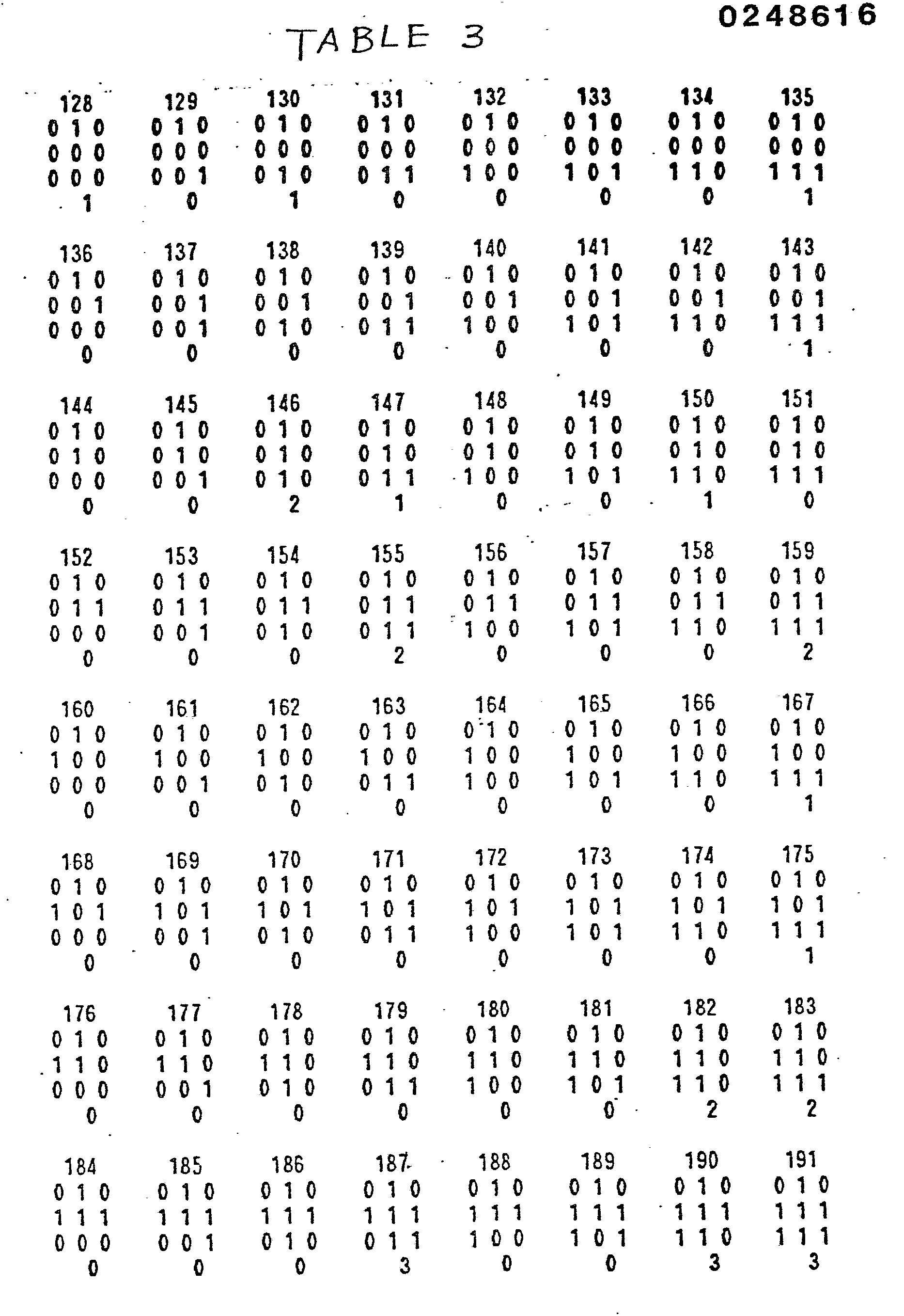
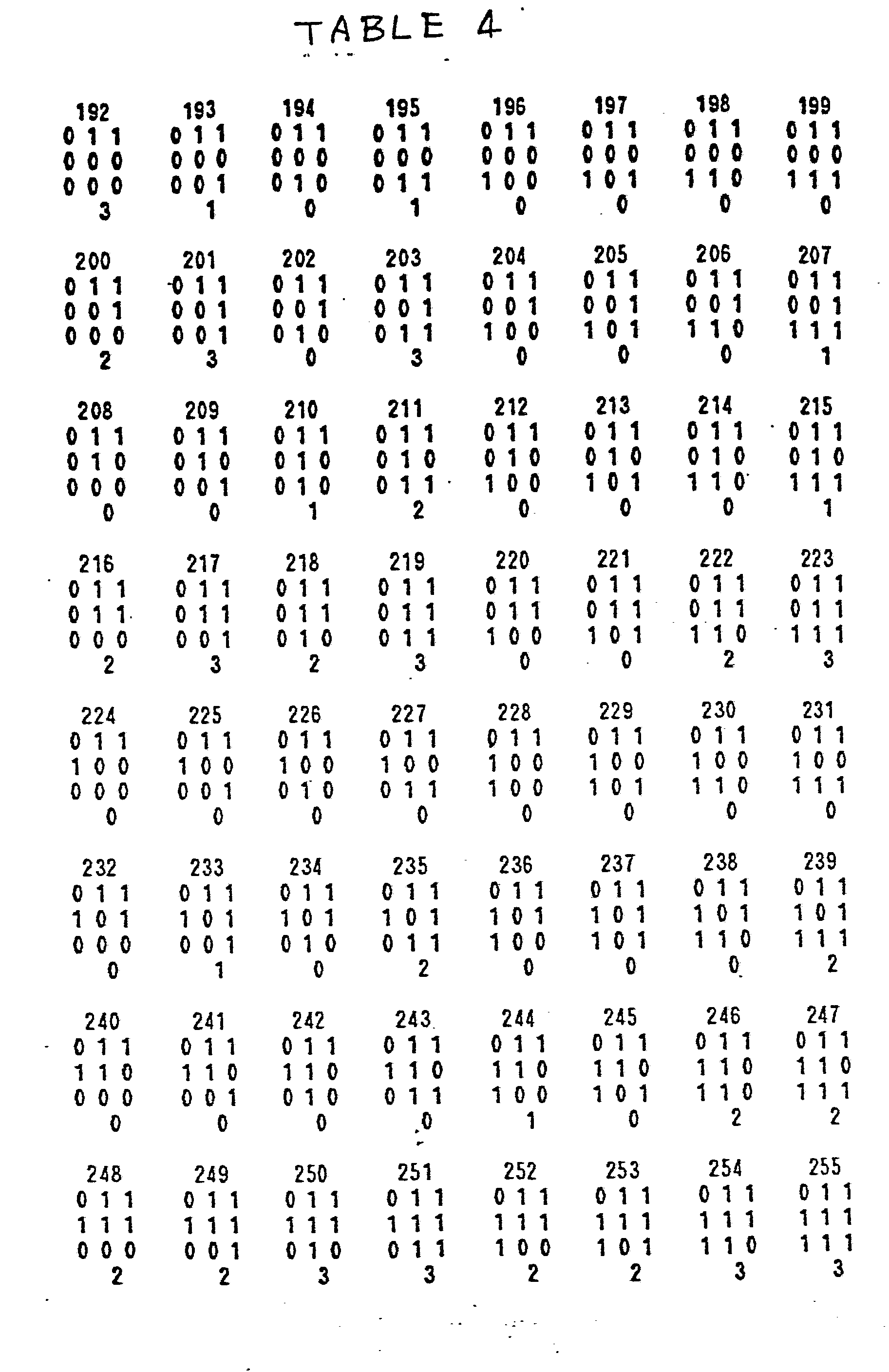
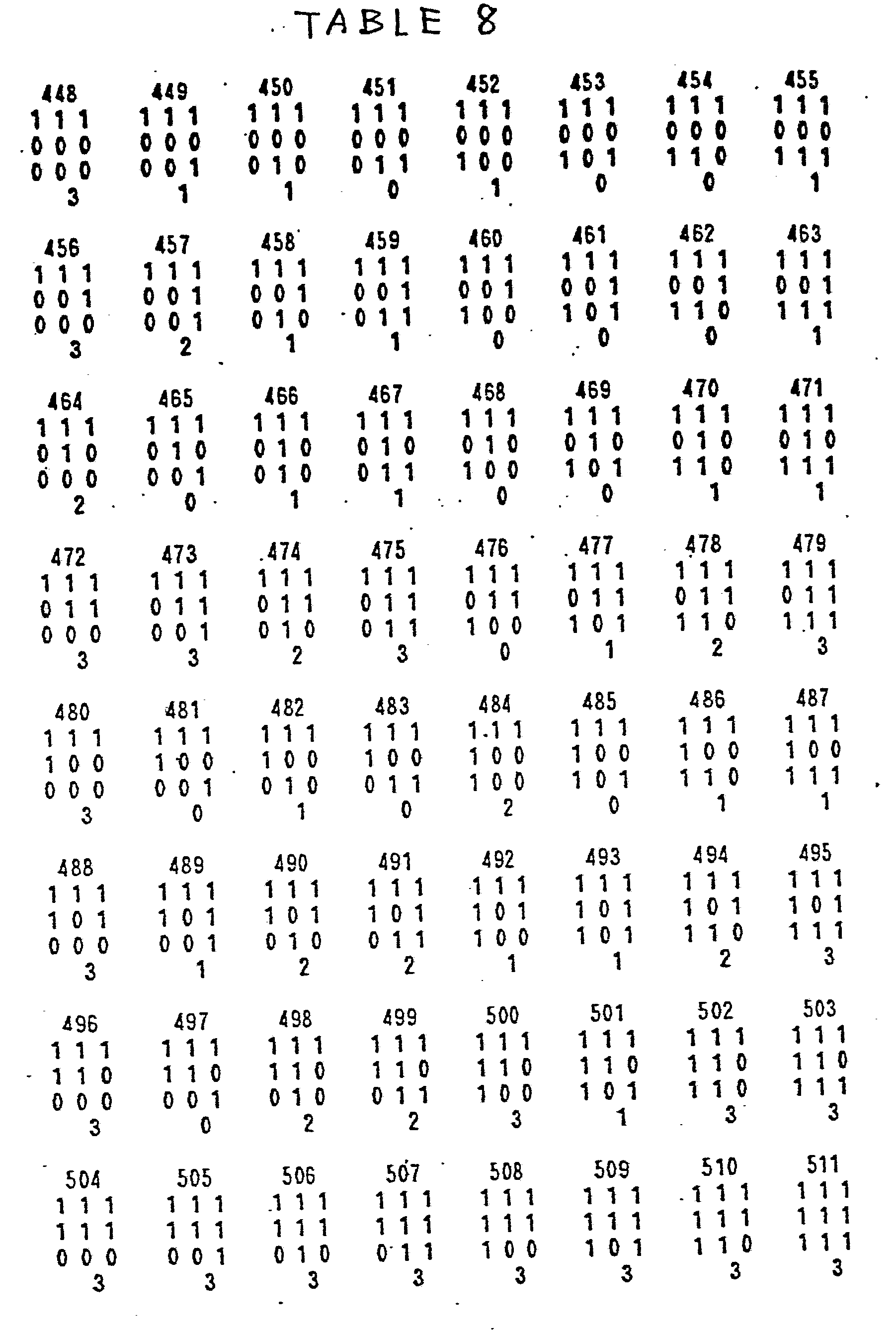
- tables 1 to 8 show the binary Laplacian signal patterns in which the address numbers and the binary Laplacian signal patterns are indicated by "0","1” patterns, and the results of judgement (the contents of the ROM49 ) are indicated by “0” (corresponding to above-mentioned code “00") "1” (corresponding to above-mentioned code “01”), "2” (corresponding to above-mentioned code “10”), and "3” (corresponding, to above-mentioned code “11”).
- the code “0” expresses the multivalence picture
- 3 expresses the binary picture
- "1" or "2” express the "no judgement" picture.
- the printing mode setting signal a control signal from the CPU 1
- the judgement ROM 49 With this signal,"the judgement level can be changed and the judgement result of multivalence pictures, binary pictures, etc. can be forcibly output irrespective of the type of original picture.
- the present invention is not limited to the said embodiment, but it is also possible to substitute- ROM pattern table 60, as shown in Fig. 14 for the multivalence, binary and dither switching circuit 11 and the binary and dither picture concentration generation circuit 12 in Fig. 5.
- An X counter 61 and a Y counter 62 generate the address data both in t-he X direction and in the. Y direction Signals, for multivalence picture printing from these and the multivalence picture signal from the multivalence concentration pattern generation circuit 6, binary picture signals and dither picture signals from the dither/binary application circuit 8 and judgement signals from the picture type judgement circuit 10 are given to the ROM pattern table 60 as address inputs.
- binary picture signals may be used the detection of edge section as to multivalence picture signals, detection of thin lines, characters, etc. in the said embodiment the printing of multivalence pictures is divided by the multivalence concentration pattern method employing Figs. 3 and 4. that is to say, the concentration level range of multivalence picture signals is divided into - part concentration areas, fixed patterns are selected according to the existence of multivalence picture signals in which part concentration areas, and the printing energy given to dots to constitute selected fixed patterns was carried out by the method to modulate according to the concentration level of multivalence picture signals. It is also effective in case the fixed concentration pattern method as shown in Fig. 2, that is to say, the concentration pattern method employing corresponding patterns one by one at the gradation level of multivalence pictures as fixed patterns was employed.
- a dither matrix may be converted to a multivalence concentration pattern, and in that case the quality of the picture is maintained whether the switching in the multivalence, binary and dither switching circuit 11 is carried out dot by dot, picture element by picture element or in larger units.
- a judgement must be carried out on the basis of picture signals by a monochrome image sensor and a color image sensor (high resolution) in the picture reader.
- a color line image sensor 71 having low resolution and a monochrome (black and white) image sensor 72 having high resolution form the as color picture reader.
- the resolution of the color image sensor 71 is determined by the matrix size of the picture printing apparatus including the thermal head 80.
- the color picture signals read by this color image sensor 71 are input into the picture processing means 100 after having been converted to multivalence . digital signals (for example, expressed in eight bits) by an A/D converter 73a.
- a shading correction circuit 74a is a circuit to compensate for the hue, concentration, etc.
- a filtering circuit 76a is a circuit with low-pass characteristics to eliminate high-pass components unnecessary for the colors picture printing and to smooth half tone pictures.
- the monochrome image sensor 72 having high resolution has been installed in the layout as shown in Fig.. 16(a) to read the same line as the color image sensor 71.
- the resolution ratio between this monochrome image sensor 72 and f the color image sensor 71 of low resolution is 1 : 3.
- the resolution of the monochrome image sensor is three times higher than the resolution of the color image sensor 71. This is because the color image sensor 71 is required to read portions of three colors from same number of dots.
- Monochrome picture signals read by the monochrome image sensor 72 of high resolution are corrected by the shading correction circuit 74b through the A/D converter 73b, similarly to color picture signals from the color image sensor 71, and are input to the filtering circuit 76b.
- the filtering circuit 76b has a high-pass characteristic different from the filtering circuit 76a, and passes sharp variations of input picture signals.
- the output of this filtering circuit 76b is utilized in the binary judgement circuit 77 in the next stage as an edge detection signal for binary pictures.
- the binary judgement circuit 77 determines which portions of a picture are multivalenct and which portions are binary from the output of the filtering circuit 76b, and generates a switching signal for multivalence/binary printing.
- a color conversion circuit 78 converts three-color (for example, R, G and B) picture signals read by the color image sensor 71 to the four -colors of yellow, magenta, cyan and black necessary for the thermal copy printing. Also, the circuit 78 determines the binary picture concentration and color determination in the areas judged as binary.
- the multivalence pattern printing circuit 79 converts the data of multivalence picture signals to multivalence patterns of N x M.
- the circuit 79 also converts the multivalence patterns to corresponding printing pulse widths.
- the pulse widths correspond to values of printing energy.
- the thermal head in the color picture printing means is driven in response to this pulse width, and carries out the thermal copy printing.
- this multivalence pattern printing circuit 79 is used for printing mixed multivalence/binary pictures.
- the circuit 79 divides the concentration level range of multivalence picture signals into partial concentration areas, for example, low-concentration area, medium- concentration area and high-concentration area, employs three fixed patterns "A” to "C” in correspondence with these partial concentration areas, and modulates the printing energy for each dot composing the fixed patterns "A” to “C” according to the concentration level of the multivalence picture signals.
- the printing energy for each dot is individually modulated according to the binary picture signal.
- a switching circuit 84 switches and .. - outputs the output of the color image sensor and the output of the monochrome image sensor 72.
- An A/D converter 85, a shading correction circuit 86, a matrix circuit 87 and a filtering circuit 88 are commonly employed both for color picture processing and monochrome picture processing.
- one dimensional image sensors 71 and 72 were utilized. However, a two dimensional image sensor may be substituted.
Abstract
Description
- This invention relates to a picture printing apparatus, and more particularly to a picture printing apparatus wherein the picture is printed based upon the features of an original picture.
- .A thermal transfer printing system is a transfer system which transfers the ink of an inkfilm coated with thermal melting or thermal sublimating ink to the printing paper by a thermal head. The thermal head is heated by applying power to a thermal resistance element. A thermal transfer printing system using the thermal melting ink is suitable particularly for binary images having only "1" and "0" concentration levels. For multivalence pictures, a special concentration modulation technique is necessary. For this concentration modulation technique, a pseudo halftone printing system for expressing the halftone picture has been attempted by modifying dot density or the ink occupation ratio over a constant area. This is a system widely used to display the gradations with a dot printer that has only the - binary concentration expression ability. Typical examples of this method include the dither method, fixed concentration pattern method and multivalence concentration pattern method.
- With the dither method, the concentration level of dots in portions of the original picture are compared with threshold levels corresponding to the location of those portions. The dots of a given portion are only printed when the threshold level is exceeded. The dither method is a method to make multivalence pictures in a binary way using threshold patterns (shown in Fig.l), and the thermal energy supplied to every dot is the same. Therefore this dither method prints a picture in accordance with a variable : gradation by controlling the number of printing dots and the ink occupation ratio in a given part of the picture.
- With the fixed concentration pattern method, dots are printed according to the element pattern shown in Fig.2 based on the dot concentration of the corresponding picture element of the original picture.
- A multivalence concentration pattern method has been developed by the present inventors, as described in U.S. Patent Application S.N.821,954. With the dither method and the fixed concentration pattern method, it is difficult to obtain clear and natural pictures taking into account the visual characteristics of the human being. Further, owing to the adverse influence of the thermal storage effect in the thermal head, discontinuities of gradation are formed in the medium and high concentration areas , uneveness results from unstable ink adhesion in the low and medium concentration areas,and so on.
- According to this multivalence concentration pattern method developed by the present inventors, the thermal storage effect of the thermal head that was considered conventionally to be a hindrance in producing good prints, can be positively utilized, and smooth pictures of high quality can be produced with a stabilized gradation .
- This multivalence concentration pattern method utilizes three dot patterns "A","B"and "C", corresponding to the low, medium and high concentration levels, respectively, and also corresponding to the energy areas supplied to the thermal head. The energy areas are mutually related to the printing concentration.
- For example,as shown in Figs. 3 and 4, the low concentration fixed pattern "A" is an isolated dot pattern formed by isolating one dot in a picture element, and the gradations in the low concentration area are expressed by modulating the printing energy ( energy supplied to the thermal head) and changing the dot size. The medium concentration fixed pattern "B" is a stripe shaped pattern extending in the relative transfer direction (subscanning direction) between the thermal head and printing paper, and the gradations in the medium concentration area are expressed by changing the stripe width by the energy supplied to the thermal head. Furthermore, the high concentration fixed pattern "C" is an L-shaped pattern combined with a white section of dimension 2 x 2, and the gradations of high concentration are expressed by changing the size of the white section in proportion to the remainding portion of the L-shaped dot pattern.
- The concept of this multivalence concentration method was disclosed by the present inventors in Proceedings of 3rd Japanese Symposium on Non-Impact Printing Technologies Symposium, reporting the results of the Symposium held on July 24 and 25, 1986.
- Either the multivalence concentration pattern method or the fixed concentration pattern method may be used for good quality printing of multivalence pictures, but if the multivalence pattern method is used for printing binary pictures, poor quality pictures result because the matrix is enlarged. For this reason, mixed multivalence and binary pictures cannot be printed clearly, because the binary portion has such a low resolution.
- Thus, there is a problem of decreased resolution when binary pictures are printed by using the fixed concentration pattern method or the multivalence concentration pattern method.
- Another printing method was proposed in Laid Open Japanese Application No.1986-82577 for printing mixed pictures of the multivalence and binary type. In this system,pictures are printed by either the binary printing method or the dither method, or a combination of the two, with halftone pictures being printed by the dither method. All gradational parts are printed by the dither method. Thus, due to the influence of the thermal storage effect in the medium and high concentration areas, all of the adverse effects described previously are encountered.
- It is an object of the present invention to provide a new and improved printing apparatus particularly suitable for printing pictures with mixed binary picture elements and halftone picture elements.
- According to a first aspect of the present invention, a picture printing apparatus for reproducing an original image comprises means for detecting the picture signal from each of a plurality of individual areas on the original image, each area being divided into a plurality of dot segments; means for generating a multivalence concentration pattern including a variable dot value corresponding to each dot segment of the original image in response to the detecting means; means responsive to the detecting means for generating a binary pattern including one of two fixed dot values corresponding to each dot segment of the original image; means for selecting the dot value from one of the binary and multivalence patterns corresponding to each individual dot segment to be printed; and means for printing dots in the dot segments corresponding to the selected dot values in response to the selecting means for reproducing the original image.
- According to a second aspect of the present invention, a picture printing apparatus for reproducing an original color image based comprises means for detecting the picture signal from each of a plurality of individual areas on the original image, each area being divided into a plurality of dot segments, including a high resolution sensor and a low resolution sensor; means for generating a multivalence concentration pattern including a variable dot value corresponding to each dot segment of the original image in response to the low resolution sensor; means responsive to the low resolution sensor for generating a binary pattern including one of two fixed dot values corresponding to each dot segment of the original image; means responsive to the high resolution sensor for selecting the dot value from one of the binary and multivalence patterns corresponding to each individual dot segment to be printed; and means for printing dots in the dot segments corresponding to the selected dot values in response to the selecting means.
- In order that the invention may be more readily understood, it will now be described, by way of example only, with reference to the accompanying drawings, in which:-
- Figures 1 to 4 illustrate prior art printing systems;
- Figure 5 is a block diagram of an embodiment of the present invention;
- Figure 6 illustrates dot patterns of an embodiment of the present invention;
- Fig. 7 is a time chart to explain the operation of the present invention;
- Figs. 8 and 9 are detailed block diagrams of the main portion of the embodiment of Fig. 5;
- Fig. 10 is Laplacian signal analysis chart of the
ROM 49 of Fig.9; - Fig. 11 is a typical dot matrix pattern used in this invention;
- Figs. 12 and 13 show examples of dot print patterns of the invention;
- Fig. 14 is a detailed block diagram of the main portion of the embodiment of Fig. 5;
- Fig. 15 is a block diagram of the another embodiment of the present invention;
- Fig. 16 shows the operation of the embodiment of Fig. 15;
- Fig. 17 is a block diagram of a further embodiment of the present invention.
- As illustrated in Fig. 5, the apparatus of the present ivention includes a
CPU 1, used to control the whole unit, aprint control circuit 15 and atiming circuit 16. Apicture reader 2 generates picture signals by reading pictures (original pictures) including the halftone portions thereof. Picture signals are converted and output as multivalence digital signals (for example,expressed as 8 bits per picture element). Aframe memory 3 stores the picture signals generated by thepicture reader 2. The frame memory 3_is not required in case the picture read operation and printing output operation are not separated in terms of the time. - The output of the
frame memory 3 is input into a multivalence concentrationpattern generation circuit 6 through anaveraging circuit 4 and aline memory 5, and signals for multivalence picture printing are generated. That is to say, theaveraging circuit 4 is a circuit to carry out the averaging processing of M X M corresponding to M X N dots of the multivalence concentration pattern matrix size on the multivalence picture signal data from theframe memory 5. This averaged data is transferred one line at a time to the line memory 5 (portion of N lines before averaging). The multivalence concentrationpattern generation circuit 6 generates signals for multivalence picture printing of the multivalence concentration patterns composed of matrices of M X N dots, employing the data in this portion of one line. These signals for multivalence picture printing enlarge the pattern size to M times in the main scanning direction, and to N times in the subscanning direction (N lines), respectively, against the multivalence picture signals input into the multivalence concentrationpattern generation circuit 6. Therefore, averaged multivalence picture signals are supplied to theline memory 5 from theaveraging circuit 4 one line at a time. The multivalence concentrationpattern generation circuit 6 is controlled by a matrixaddress generation circuit 7. - A dither/
binary circuit 8 carrys out the dither processing and binary processing for picture signals output from theframe memory 3, and generates dither picture signals and_binary picture signals. - The output signals of the
frame memory 3 are applied to picturetype judgement circuit 10 through afilter circuit 9. The picturetype judgement circuit 10 determines whether the input picture is a multivalence picture or a binary picture. There are cases when this judgement cannot be made, and in such cases, thejudgement circuit 10 outputs a different signal corresponding to this condition. - A multivalence, binary and
dither switching circuit 11 switches the printing picture mode on the basis of the judgement result of the picturetype judgement circuit 10. In case the judgement result of thejudgement circuit 10 indicates a multivalent picture, signals for multivalence picture recording from the multivalence concentrationpattern generation circuit 6 are output. Further, in case the judgement result indcates binary pictures, binary picture signals from the dither/binary circuit 8 are output after being individually modulated. Further, in case the judgement result is indefinite (no judgement), dither picture signals from the dither/binary circuit 8 are output after being modulated. The multivalence, binary anddither switching circuit 11 carries out its switching dot by dot. Fig. 6 shows this aspect. Fig. 6 (a) shows the data of signals for multivalence picture printing, after conversion to multivalence concentration patterns in the multivalence concentrationpattern generation circuit 6, and Fig 6 (b) and Fig 6 (c) show the data of dither pictures and binary pictures obtained in the dither/binary circuit 8, respectively. Further, Fig. 6 (d) is an example of the judgement output in the picturetype judgement circuit 10. "A" shows the judgement result for multivalence pictures, "B" for indefinite (no judgement), and "C" for binary pictures, respectively. The multivalence, binary anddither switching circuit 11 switches printing output pictures in accordance with this judgement result, and this switching can be changed as shown in Figs. 6 (e) and (f) whether binary pictures or multivalence concentration pictures are present. - A binary and dither picture
concentration generation circuit 12 generates signals corresponding to the necessary printing energy (supplying energy of the thermal head) so that printed dots are of a proper size. Theexpressions ⑤ on the pattern shown in Fig. 6 correspond to the printing concentration of binary pictures. - Signals for multivalence picture printing thus output from the multivalence, binary and
dither switching circuit 11 are supplied to a thermalhead drive circuit 13. The thermalhead drive circuit 13 converts the multivalence concentration patterns given by signals for multivalence picture printing to the pulse width of pulses to drive the thermal head in thethermal transfer printer 14. Thedrive circiut 13 also controls the supply of energy to the thermal head. Theprinting control circuit 15 controls thethermal transfer printer 14, and accurately carries out the transport, control, etc. of the ink ribbon, printing paper, etc. by the commands from theCPU 1. Atiming circuit 16 generates synchronous signals of one line that are required in case the data of picture signals is transferred, and supplies the synchronous signals to the required circuit. For example, the timing circuit may act as a timing clock for data transfer. - Fig. 7 is a timing chart to show the operation of the present embodiment, and one cycle of dot clock corresponds to the printing time of one dot by the thermal head. Multivalence picture signals are switched once in four cycles of dot clock. In the meantime, the multivalence concentration
pattern generation circuit 6 is controlled by the matrixaddress generation circuit 7, and signals for multivalence picture printing of four dots are generated. On the other hand, binary picture signals and dither picture signals from the dither/binary circuit 8 are input as data corresponding to one dot, and the printing energy given to each dot of signals for multivalence picture printing is modulated by this binary picture signal. That is to say, among systems of signals for multivalence picture printing, the printing energy that binary picture signals and dither picture signals give to dots of "1' is demodulated, as shown in Fig. 6 (e) or (f), and finally theprinting signal output - In this way, it is possible to print mixed multivalent and binary pictures by the multivalence concentration pattern method and the binary method corresponding to one dot of thermal head per picture element.
- The dither/
binary circuit 8 carrys out the dither application processing and binary application processing for picture signals from theframe memory 3 and generates dither picture signals and binary picture signals. - The specific configuration of the dither/
binary circuit 8 is shown in Fig. 8. In Fig. 8, the multivalence picture signal data read from theframe memory 3 shown in Fig. 5 is input into a dithermatrix table ROM 31 and acomparator 33. The ROM 31 is controlled by amatrix position counter 32 for matrix position setting.ROM 31 modulates the picture signal data input by dither patterns composed of M x N matrices, and outputs dither picture signals as data arrays of one bit. In addition, the M x N matrix size at the time of this dither application may be the same as the M x N of matrix size of multivalence concentration patterns. Thecomparator 33 receives the picture signal data from theframe memory 3 at the threshold level (binary application level).The - threshold level is determined by the binarylevel setting circuit 34.Comparator 33 also outputs binary picture signals composed of data arrays of one bit. Further, it is also possible to vary the tone or concentration of the binary processing by changing the set level of the binary signal. - Fig. 9 shows in detail the configurations of
filter circuit 9 and picturetype judgement circuit 10. Three dot portions of the multivalence picture signal data from theframe memory 3 are added in the sub scanning direction and three dot portions are added in the main scanning direction, totaling nine dot portions of a picture element. That is to say, the multivalence picture signal data in a portion of two lines is held by theline delay circuits 42a and 42b through theline switching circuit 41. These are added by the adder 43a, and this addition result and the multivalence picture data in the a portion of another line (output of the delay circuit 44a) are added by theadder 43b. The results for each of these additions are consecutively delayed by the delay circuits 44c to 44e, and the output of these delay circuits 44c to 44e is added by the adders 43c and 43d, resulting in a total value for each successive nine dot matrix series. - A mean value for each picture is read from the
ROM 45 based upon the total added result for eacn successiive nine dot matrix. The mean value added from theROM 45 is the binary complement of 1/9 of the added result. A high-pass component of the original picture signal is used to judge the type of the picture. The highpass component is extracted by adding the averaged picture signal data (output of the ROM45) and the original picture signal data (output of the delay circuit 44b) with the adder 43(e). The addition by the adder 43(e) is synchronized in accordance with the delay circuits 44(a) and 44(b). - The high-pass component of the averaged value of nine dot portions from the
filter circuit 9 is input into the picturetype judgement circuit 10. After being applied to thebinary application circuit 46, the signal is consecutively delayed by the line delay circuits 48a to 48c through theline switching circuit 47. The data of nine dot portions, which includes data on three dots output from each of the line delay circuits 48a to 48c, is input into thejudgement ROM 49, and the judgement of multivalence, binary or indefinite is carried out. - Next,the operation of the
judgement ROM 49 is explained. Examination was made of the distribution of binary Laplacian and dot picture. The results were obtained as shown in Fig.10. In this Figure,the abscissa represents the arrangement of binary Laplacian signals in a matrix of 3 x 3 and the ordinate represents the frequency with which the arrangement of binary Laplacian signals occurs. The arrangement of binary Laplacian signals consists of nine bits of data whose MSB and LSB correspond to ill and 133 in the 3 x 3 matrix shown in Fig.11, respectively. For example,where only the binary Laplacian signal corresponding to ill is 1, the nine bit data is given by "100000000". At the left end of the abscissa, all binary Laplacian signals for the 3 x 3 matrix are 0 and, at the right end thereof, all binary Laplacian signals are 1. As seen from the result shown in Fig. 10(a) in the case of character pictures,such patterns of binary Laplacian signals as shown in Fig.12 (a), (b) and (c) appear with a higher frequency. In this case,there is a tendency that not only white dots, but also black dots, are arranged side by side to some extent. This tendency coincides with the qualitative tendency of a character pattern. - On the other hand-, the result shown in Fig.11(b) typicallyis obtained with respect to dot pictures. As seen,such patterns of binary Laplacian signals as shown in Figs.l3(a),13(b) and 13(c) appear with a higher frequency. This indicates the qualitative tendency of dot pictures, where neither white dots nor black dots are normally continuously arranged but have a more periodic pattern. In Figs.12 and 13, portions where oblique lines are drawn each represent the binary Laplacian signal of "1" and portions where no lines are drawn each represent the binary Laplacian signal of "I", and portions where no lines are drawn each represent the binary Laplacian signal of "0".
- Accordingly, discrimination of the type of input pictures becomes possible by examining the magnitude of Laplacian signals and the distribution of binary Laplacian signals. For this reason, in the
filter circuit 9, the Laplacian signals are binary encoded and the address signal indicating the distribution of binary Laplacian signals in the 3 x 3 pixel array is applied to theROM 49. - The contents of the
ROM 49 are determined by comparing the normal appearance frequencies of binary Laplacian signals for letter-like pictures and dot-like pictures,and for example, determining the difference between those frequencies. In cases where the appearance frequency for letter-like pictures is greater than for dot-like pictures, one pattern is assigned as a letter-like picture defined by the code "1I". Where it is determined that the frequency for dot-like pictures is greater, the code "00" is assigned. When the difference does not exceed specified level,the pattern is assigned as a "no judgement" picture with a code "10" or "01". The code "10" is assigned when the appearance frequency of the binary Laplacian signal pattern for letter-like pictures is largest, and the code "01" is assigned when the dot-like picture frequency is largest. - Next, tables 1 to 8 show the binary Laplacian signal patterns in which the address numbers and the binary Laplacian signal patterns are indicated by "0","1" patterns, and the results of judgement (the contents of the ROM49 ) are indicated by "0" (corresponding to above-mentioned code "00") "1" (corresponding to above-mentioned code "01"), "2" (corresponding to above-mentioned code "10"), and "3" (corresponding, to above-mentioned code "11"). Thus,the code "0" expresses the multivalence picture,"3" expresses the binary picture and "1" or "2" express the "no judgement" picture.


- Further, the printing mode setting signal, a control signal from the
CPU 1, is input into thejudgement ROM 49. With this signal,"the judgement level can be changed and the judgement result of multivalence pictures, binary pictures, etc. can be forcibly output irrespective of the type of original picture. - In addition, the present invention is not limited to the said embodiment, but it is also possible to substitute- ROM pattern table 60, as shown in Fig. 14 for the multivalence, binary and
dither switching circuit 11 and the binary and dither pictureconcentration generation circuit 12 in Fig. 5. AnX counter 61 and aY counter 62 generate the address data both in t-he X direction and in the. Y direction Signals, for multivalence picture printing from these and the multivalence picture signal from the multivalence concentrationpattern generation circuit 6, binary picture signals and dither picture signals from the dither/binary application circuit 8 and judgement signals from the picturetype judgement circuit 10 are given to the ROM pattern table 60 as address inputs. In addition, it is also possible to combine the multivalence concentrationpattern generation circuit 6 and picturetype judgement circuit 10 into the ROM pattern table 60. - Further, binary picture signals may be used the detection of edge section as to multivalence picture signals, detection of thin lines, characters, etc. in the said embodiment the printing of multivalence pictures is divided by the multivalence concentration pattern method employing Figs. 3 and 4. that is to say, the concentration level range of multivalence picture signals is divided into - part concentration areas, fixed patterns are selected according to the existence of multivalence picture signals in which part concentration areas, and the printing energy given to dots to constitute selected fixed patterns was carried out by the method to modulate according to the concentration level of multivalence picture signals. It is also effective in case the fixed concentration pattern method as shown in Fig. 2, that is to say, the concentration pattern method employing corresponding patterns one by one at the gradation level of multivalence pictures as fixed patterns was employed.
- In case of the fixed concentration pattern method, since the print.ing energy of each dot only takes the binary ,value, the binary and dither picture
concentration generation circuit 12 in Fig.5 becomes unnecessary. - Further, a dither matrix may be converted to a multivalence concentration pattern, and in that case the quality of the picture is maintained whether the switching in the multivalence, binary and
dither switching circuit 11 is carried out dot by dot, picture element by picture element or in larger units. - When color pictures are read by the
picture reader 2, a judgement must be carried out on the basis of picture signals by a monochrome image sensor and a color image sensor (high resolution) in the picture reader.As shown in Fig. 15, a colorline image sensor 71 having low resolution and a monochrome (black and white)image sensor 72 having high resolution form the as color picture reader. The resolution of thecolor image sensor 71 is determined by the matrix size of the picture printing apparatus including thethermal head 80. The color picture signals read by thiscolor image sensor 71 are input into the picture processing means 100 after having been converted to multivalence . digital signals (for example, expressed in eight bits) by an A/D converter 73a. - In the picture processing means 100, first the illumination unevenness on the copy surface and sensitivity unevenness of the
color image sensor 71 are corrected by ashading correction circuit 74a. Amatrix circuit 75 is a circuit to compensate for the hue, concentration, etc. A filtering circuit 76a is a circuit with low-pass characteristics to eliminate high-pass components unnecessary for the colors picture printing and to smooth half tone pictures. - The
monochrome image sensor 72 having high resolution has been installed in the layout as shown in Fig.. 16(a) to read the same line as thecolor image sensor 71. The resolution ratio between thismonochrome image sensor 72 and f thecolor image sensor 71 of low resolution is 1 : 3. Thus, if the number of dots of the monochrome image sensor is the same as the total number of dots of thecolor image sensor 71,the resolution of the monochrome image sensor is three times higher than the resolution of thecolor image sensor 71. This is because thecolor image sensor 71 is required to read portions of three colors from same number of dots. - Monochrome picture signals read by the
monochrome image sensor 72 of high resolution are corrected by the shading correction circuit 74b through the A/D converter 73b, similarly to color picture signals from thecolor image sensor 71, and are input to the filtering circuit 76b. The filtering circuit 76b has a high-pass characteristic different from the filtering circuit 76a, and passes sharp variations of input picture signals. The output of this filtering circuit 76b is utilized in thebinary judgement circuit 77 in the next stage as an edge detection signal for binary pictures. Thebinary judgement circuit 77 determines which portions of a picture are multivalenct and which portions are binary from the output of the filtering circuit 76b, and generates a switching signal for multivalence/binary printing. - A
color conversion circuit 78 converts three-color (for example, R, G and B) picture signals read by thecolor image sensor 71 to the four -colors of yellow, magenta, cyan and black necessary for the thermal copy printing. Also, thecircuit 78 determines the binary picture concentration and color determination in the areas judged as binary. - The multivalence
pattern printing circuit 79 converts the data of multivalence picture signals to multivalence patterns of N x M. Thecircuit 79 also converts the multivalence patterns to corresponding printing pulse widths. The pulse widths correspond to values of printing energy. The thermal head in the color picture printing means is driven in response to this pulse width, and carries out the thermal copy printing. - Further, this multivalence
pattern printing circuit 79 is used for printing mixed multivalence/binary pictures. Thecircuit 79 divides the concentration level range of multivalence picture signals into partial concentration areas, for example, low-concentration area, medium- concentration area and high-concentration area, employs three fixed patterns "A" to "C" in correspondence with these partial concentration areas, and modulates the printing energy for each dot composing the fixed patterns "A" to "C" according to the concentration level of the multivalence picture signals. - In the case of binary pictures, the printing energy for each dot is individually modulated according to the binary picture signal.
- Thus, in this embodiment the color picture processing system and monochrome picture processing system were separate. As shown in Fig. 17, it is also possible to combine these two processing systems in a color- copying machine. In Fig. 17 a
switching circuit 84 switches and .. - outputs the output of the color image sensor and the output of themonochrome image sensor 72. An A/D converter 85, a shading correction circuit 86, amatrix circuit 87 and afiltering circuit 88 are commonly employed both for color picture processing and monochrome picture processing. - Further, in this embodiment one
dimensional image sensors - Further, in this embodiment it was judged whether images were multivalent or binary, and color picture signals were generated on the basis of that judgment. However, for example, edge detection of pictures may be carried out on the basis of picture signals from the monochrome image sensor, while color picture signals to generate an image with monochrome-generated edge emphasis treatment. In above-mentioned embodiment shown in Figs.16 and 17, the results of judgement are only binary or multivalent, because unjustiable picture is provided the dither method described in Fig. 5.
Claims (3)
Applications Claiming Priority (4)
| Application Number | Priority Date | Filing Date | Title |
|---|---|---|---|
| JP127617/86 | 1986-06-02 | ||
| JP61127617A JPS62284577A (en) | 1986-06-02 | 1986-06-02 | Color image processor |
| JP61303672A JPS63157558A (en) | 1986-12-22 | 1986-12-22 | Image recorder |
| JP303672/86 | 1986-12-22 |
Publications (2)
| Publication Number | Publication Date |
|---|---|
| EP0248616A2 true EP0248616A2 (en) | 1987-12-09 |
| EP0248616A3 EP0248616A3 (en) | 1990-03-07 |
Family
ID=26463531
Family Applications (1)
| Application Number | Title | Priority Date | Filing Date |
|---|---|---|---|
| EP87304815A Withdrawn EP0248616A3 (en) | 1986-06-02 | 1987-06-01 | Picture printing apparatus |
Country Status (1)
| Country | Link |
|---|---|
| EP (1) | EP0248616A3 (en) |
Cited By (9)
| Publication number | Priority date | Publication date | Assignee | Title |
|---|---|---|---|---|
| EP0336403A2 (en) * | 1988-04-06 | 1989-10-11 | Canon Kabushiki Kaisha | Image reading apparatus |
| EP0356225A2 (en) * | 1988-08-24 | 1990-02-28 | Canon Kabushiki Kaisha | Image processing apparatus |
| EP0382580A2 (en) * | 1989-02-10 | 1990-08-16 | Canon Kabushiki Kaisha | Image processing apparatus |
| WO1991009489A2 (en) * | 1989-12-14 | 1991-06-27 | Eastman Kodak Company | Mixed matrix image processing for rendering halftone images with variable dot sizes |
| US5121446A (en) * | 1989-02-10 | 1992-06-09 | Canon Kabushiki Kaisha | Image processing apparatus capable of obtaining multi-level data |
| EP0501767A2 (en) * | 1991-02-26 | 1992-09-02 | Matsushita Graphic Communication Systems, Inc. | Facsimile apparatus determining type of received image to select printing device |
| US5198910A (en) * | 1989-12-14 | 1993-03-30 | Eastman Kodak Company | Mixed matrix image processing for rendering halftone images with variable dot sizes |
| WO1993026116A2 (en) * | 1992-06-05 | 1993-12-23 | Eastman Kodak Company | Method and apparatus for reproducing an image with gray level printing |
| EP0579177A2 (en) * | 1992-07-13 | 1994-01-19 | Mita Industrial Co., Ltd. | Color image processing apparatus |
Citations (3)
| Publication number | Priority date | Publication date | Assignee | Title |
|---|---|---|---|---|
| US4194221A (en) * | 1978-12-26 | 1980-03-18 | Xerox Corporation | Automatic multimode continuous halftone line copy reproduction |
| JPS57193376A (en) * | 1981-05-23 | 1982-11-27 | Nippon Telegr & Teleph Corp <Ntt> | Character and halftone image recording system |
| US4467195A (en) * | 1977-12-08 | 1984-08-21 | Canon Kabushiki Kaisha | Information detecting apparatus |
-
1987
- 1987-06-01 EP EP87304815A patent/EP0248616A3/en not_active Withdrawn
Patent Citations (3)
| Publication number | Priority date | Publication date | Assignee | Title |
|---|---|---|---|---|
| US4467195A (en) * | 1977-12-08 | 1984-08-21 | Canon Kabushiki Kaisha | Information detecting apparatus |
| US4194221A (en) * | 1978-12-26 | 1980-03-18 | Xerox Corporation | Automatic multimode continuous halftone line copy reproduction |
| JPS57193376A (en) * | 1981-05-23 | 1982-11-27 | Nippon Telegr & Teleph Corp <Ntt> | Character and halftone image recording system |
Non-Patent Citations (2)
| Title |
|---|
| IEEE TRANSACTIONS ON ELECTRON DEVICES, vol. ED-30, no. 8, August 1983, pages 898-904, IEEE, New York, US; Y. TOKUNAGA et al.: New gray-scale printing method using a thermal printer" * |
| PATENT ABSTRACTS OF JAPAN, vol. 7, no. 44 (M-195)[1189], 22nd February 1983; & JP-A-57 193 376 (NIPPON DENSHIN DENWA KOSHA) 27-11-1982 * |
Cited By (19)
| Publication number | Priority date | Publication date | Assignee | Title |
|---|---|---|---|---|
| EP0336403A3 (en) * | 1988-04-06 | 1991-07-17 | Canon Kabushiki Kaisha | Image reading apparatus |
| EP0336403A2 (en) * | 1988-04-06 | 1989-10-11 | Canon Kabushiki Kaisha | Image reading apparatus |
| US5488673A (en) * | 1988-08-24 | 1996-01-30 | Canon Kabushiki Kaisha | Image processing with fixed or variable threshold |
| EP0356225A2 (en) * | 1988-08-24 | 1990-02-28 | Canon Kabushiki Kaisha | Image processing apparatus |
| EP0356225A3 (en) * | 1988-08-24 | 1992-12-09 | Canon Kabushiki Kaisha | Image processing apparatus |
| EP0730369A1 (en) * | 1988-08-24 | 1996-09-04 | Canon Kabushiki Kaisha | Image processing apparatus |
| EP0382580A2 (en) * | 1989-02-10 | 1990-08-16 | Canon Kabushiki Kaisha | Image processing apparatus |
| EP0382580A3 (en) * | 1989-02-10 | 1991-10-02 | Canon Kabushiki Kaisha | Image processing apparatus |
| US5121446A (en) * | 1989-02-10 | 1992-06-09 | Canon Kabushiki Kaisha | Image processing apparatus capable of obtaining multi-level data |
| WO1991009489A2 (en) * | 1989-12-14 | 1991-06-27 | Eastman Kodak Company | Mixed matrix image processing for rendering halftone images with variable dot sizes |
| WO1991009489A3 (en) * | 1989-12-14 | 1991-08-22 | Eastman Kodak Co | Mixed matrix image processing for rendering halftone images with variable dot sizes |
| US5198910A (en) * | 1989-12-14 | 1993-03-30 | Eastman Kodak Company | Mixed matrix image processing for rendering halftone images with variable dot sizes |
| EP0501767A2 (en) * | 1991-02-26 | 1992-09-02 | Matsushita Graphic Communication Systems, Inc. | Facsimile apparatus determining type of received image to select printing device |
| EP0501767A3 (en) * | 1991-02-26 | 1993-03-17 | Fujitsu Limited | Facsimile apparatus determining type of received image to select printing device |
| WO1993026116A3 (en) * | 1992-06-05 | 1994-04-14 | Eastman Kodak Co | Method and apparatus for reproducing an image with gray level printing |
| WO1993026116A2 (en) * | 1992-06-05 | 1993-12-23 | Eastman Kodak Company | Method and apparatus for reproducing an image with gray level printing |
| EP0579177A2 (en) * | 1992-07-13 | 1994-01-19 | Mita Industrial Co., Ltd. | Color image processing apparatus |
| EP0579177A3 (en) * | 1992-07-13 | 1994-03-16 | Mita Industrial Co Ltd | |
| US5515096A (en) * | 1992-07-13 | 1996-05-07 | Mita Industrial Co., Ltd. | Color image processing apparatus with processing means for selectively adjusting color image data to increase black color density and reduce the density of other colors |
Also Published As
| Publication number | Publication date |
|---|---|
| EP0248616A3 (en) | 1990-03-07 |
Similar Documents
| Publication | Publication Date | Title |
|---|---|---|
| US5325211A (en) | Error diffusion with output and input based feedback | |
| EP0369778B1 (en) | Image recording apparatus | |
| EP0533411A2 (en) | Color printing yielding a dense black image | |
| US5175635A (en) | Picture printing apparatus using multivalued patterns, binary patterns and dither patterns selectively | |
| JPH10334228A (en) | Method for improving resolution of raster image | |
| US5252986A (en) | Image processing method for superposing plural dots on a recording medium at a predetermined interval and apparatus utilizing same | |
| US6069636A (en) | Embedding information into images by varying pixel parameters | |
| US5565907A (en) | Image forming apparatus capable of producing high quality halftone images | |
| EP0987879B1 (en) | Methods of gradation control and picture quality improvement in thermal printer | |
| EP0342853A1 (en) | Electronic print dot generation | |
| JPH08116464A (en) | Colored picture processing and picture processor | |
| US6842268B1 (en) | Printing of digital color images with locally adjusted half-toning | |
| EP0248616A2 (en) | Picture printing apparatus | |
| EP0694868B1 (en) | Imaging apparatus with toner saving means | |
| EP0292292B1 (en) | Image processing apparatus | |
| US5303069A (en) | Method for producing a multitone image | |
| EP0261801A2 (en) | Color image recording apparatus | |
| US6002841A (en) | Apparatus and method for processing image which adds identification information to be easily decipherable in high resolution image | |
| JPH0720199B2 (en) | Image processing device | |
| JPS60141585A (en) | Color image forming method | |
| JP2996523B2 (en) | Image processing method | |
| JP3251348B2 (en) | Image processing apparatus and image processing method | |
| JP3030965B2 (en) | Halftone color image reproduction method and apparatus | |
| JP3604806B2 (en) | Recording device and recording method | |
| JP3489288B2 (en) | Image processing method and image processing apparatus |
Legal Events
| Date | Code | Title | Description |
|---|---|---|---|
| PUAI | Public reference made under article 153(3) epc to a published international application that has entered the european phase |
Free format text: ORIGINAL CODE: 0009012 |
|
| 17P | Request for examination filed |
Effective date: 19870623 |
|
| AK | Designated contracting states |
Kind code of ref document: A2 Designated state(s): DE FR GB |
|
| PUAL | Search report despatched |
Free format text: ORIGINAL CODE: 0009013 |
|
| AK | Designated contracting states |
Kind code of ref document: A3 Designated state(s): DE FR GB |
|
| 17Q | First examination report despatched |
Effective date: 19920323 |
|
| STAA | Information on the status of an ep patent application or granted ep patent |
Free format text: STATUS: THE APPLICATION IS DEEMED TO BE WITHDRAWN |
|
| 18D | Application deemed to be withdrawn |
Effective date: 19920804 |
|
| RIN1 | Information on inventor provided before grant (corrected) |
Inventor name: MATSUI, TOSHIKAZU Inventor name: YAMADA, KIYOSHI Inventor name: HIRAHARA, SHUZO Inventor name: HIGUCHI, KAZUHIKO |