EP0248627A2 - Instrument for monitoring foetal heart rate - Google Patents
Instrument for monitoring foetal heart rate Download PDFInfo
- Publication number
- EP0248627A2 EP0248627A2 EP87304839A EP87304839A EP0248627A2 EP 0248627 A2 EP0248627 A2 EP 0248627A2 EP 87304839 A EP87304839 A EP 87304839A EP 87304839 A EP87304839 A EP 87304839A EP 0248627 A2 EP0248627 A2 EP 0248627A2
- Authority
- EP
- European Patent Office
- Prior art keywords
- instrument
- head member
- needle
- foetal
- monitoring
- Prior art date
- Legal status (The legal status is an assumption and is not a legal conclusion. Google has not performed a legal analysis and makes no representation as to the accuracy of the status listed.)
- Withdrawn
Links
Images


Classifications
-
- A—HUMAN NECESSITIES
- A61—MEDICAL OR VETERINARY SCIENCE; HYGIENE
- A61B—DIAGNOSIS; SURGERY; IDENTIFICATION
- A61B5/00—Measuring for diagnostic purposes; Identification of persons
- A61B5/43—Detecting, measuring or recording for evaluating the reproductive systems
- A61B5/4306—Detecting, measuring or recording for evaluating the reproductive systems for evaluating the female reproductive systems, e.g. gynaecological evaluations
- A61B5/4343—Pregnancy and labour monitoring, e.g. for labour onset detection
- A61B5/4362—Assessing foetal parameters
-
- A—HUMAN NECESSITIES
- A61—MEDICAL OR VETERINARY SCIENCE; HYGIENE
- A61B—DIAGNOSIS; SURGERY; IDENTIFICATION
- A61B5/00—Measuring for diagnostic purposes; Identification of persons
- A61B5/24—Detecting, measuring or recording bioelectric or biomagnetic signals of the body or parts thereof
- A61B5/25—Bioelectric electrodes therefor
- A61B5/279—Bioelectric electrodes therefor specially adapted for particular uses
- A61B5/28—Bioelectric electrodes therefor specially adapted for particular uses for electrocardiography [ECG]
- A61B5/283—Invasive
- A61B5/288—Invasive for foetal cardiography, e.g. scalp electrodes
Definitions
- This invention relates to an instrument especially but not exclusively for monitoring foetal heart rate.
- the first successful device for monitoring foetal heart rate took the form of an insulated suture clip which could be attached to the foetal head and complete an electrical circuit with a second electrode in contact with the mother.
- Later inventions included providing the instrument's leading end with a helical electrode or pair of electrodes, which attached to the baby's head by rotation of a handle which was attached to the electrode. Over-rotation could in some cases cause the baby's scalp to be traumatised, and result in difficult removal of the electrode.
- Another device included a single arcuate needle electrode which was movable to emerge from or retract into a housing forming the active head of the device.
- an instrument for monitoring foetal heart rate comprising a body having a head member for application to the foetal scalp, an electrically conductive needle extending from the head member for penetration of the foetal scalp, a first electrical conductor extending from the needle for connection to monitoring equipment, a second electrical conductor for connection to monitoring equipment, said second conductor being insulated from the first conductor and extending from a terminal external of the body for contacting the mother in use, characterised in that the head member is flexible and the needle movable therewith, and actuating means are provided for flexing the head member.
- biassing means are provided on the head member, to bias said head member towards a preselected attitude.
- the biassing means may for example comprise a resilient membrane which engages the head member and is distorted when the head member is moved from said preselected attitude.
- the actuating means is in the form of a telescopic arrangement of members, the members being connected with different regions of the head member for flexing said head member.
- the head member comprises first and second portions which are hingedly connected to one another.
- the needle is arcuate and centred on the axis of the hinge connection between the first and second portions of the head member.
- the instrument of this embodiment of the invention has a tubular main shaft 1 of flexible plastics with a head portion 2 at its leading end 3 and a plunger 4 at its trailing end 5.
- a pair of mutually insulated electrical wires 6, 7 are carried within the bore 8 of the main shaft 1, one of the wires 6 connecting to a pair of electrodes 9, 10 of arcuate form in the head portion 2, the other wire 7 connecting to an electrode sheath 11 of coiled wire on the exterior of the main shaft 1.
- the wires 6, 7 emerge from the bore 8 at the trailing end 5 through a small bite (not shown), this end being encircled by a tube of plastic 12 with corresponding bite 13 and its cut end being plugged with a rubber stopper 14.
- the main shaft 1 is slidable within a handle 15 of the plunger 4.
- the handle 15 consists of a tube 16 coaxial with the main shaft 1 and carries a pair of wings 17 at its base.
- the base of the head portion 2 has a cylindrical mould 22 which receives the leading end 3 of the main shaft 1.
- the cord 19 emerges through a circular aperture 23 at the top of the cylindrical mould 22 and attaches to a top jaw 24 of the head portion 2.
- the arcuate electrodes 9, 10 extend rigidly from the top jaw 24 and a bottom jaw 25 of the head portion 2 respectively, protruding through small perforations 26 in a rubber membrane 27 that is glued taut over a face of the head portion 2.
- the top and bottom jaws 24, 26 are connected through a hinge 28.
- the wires 6, 7 are connected to monitoring equipment and the instrument is passed along the mother's vagina until the electrodes 9, 10 and head member 2 rest against the scalp of the foetus.
- the handle 15 is slid down over the trailing end 5 of the main shaft 1, hence pulling the cord 19 which results in the top jaw 24 pivoting relative to the bottom jaw 25 against the resistance of the rubber membrane 27.
- the membrane 27 is then in a stretched condition. With the head portion 2 pressed against the foetal scalp the plunger 4 is released and the elasticity of the rubber membrane 27 pulls the jaws 24, 25 together, causing the electrodes 9, 10 to penetrate the scalp and closely pass one another, forming a closed loop through the skin.
- the electrode sheath 11 is constantly in contact with the mother; hence, as soon as the electrodes 9, 10 are fully inserted, monitoring can be performed.
- Figs 8 to 21 of the drawings there is shown a sec ond embodiment of an instrument of the present invention.
- This embodiment has one electrode 30 in the form of an generally semi-circular needle.
- the electrode 30 is attached to the top jaw 24 and emerges from the membrane 27 at only one point, this being perforation 26.
- the tip 31 of the electrode 30 lies adjacent the membrane 27 and, in this way, the tip 31 is shielded during insertion of the instrument into a vagina.
- the top jaw 24 is almost entirely encapsulated in an arch-shaped moulded extension 32 of the lower jaw 25, such that the hinge 28 of the jaws 24, 25 is hidden and the leading edge of the instrument is not hingedly movable, thus protecting the patient from further traumas.
- Backward facing extensions 33 of the lower jaw 25 enclose the cylindrical mould 22 holding the main shaft 1 and shield the emergent cord 19 and the back of the top jaw 24.
- the extensions 33 are serrated to give a good grip for the operator's fingers when the instrument is in use.
- the main shaft 1 terminates at its trailing end 5 in a plunger 4 comprising a handle 15 and an internal slider tube 34, the slider tube 34 being fitted as an extension to the main shaft 1 and being slidable within the handle 15.
- the cord 19 extends from the bore 8 of the main shaft 1, through a slot 35 in the slider tube 34, to a funnel-shape aperture 36 in the side of the handle 15 wherein the knotted end 18 of the cord 19 is retained.
- the handle 15 is moved along the main shaft 1 to open or close the hingedly connected jaws 24,25.
Abstract
Description
- This invention relates to an instrument especially but not exclusively for monitoring foetal heart rate.
- During delivery monitoring of foetal heart rate is routine as it helps provide a complete birth record. However, the monitoring is especially important for babies at risk, as heart rate is a good indicator as to the condition of the child and the instrument therefore provides an early warning system for babies in distress.
- The first successful device for monitoring foetal heart rate took the form of an insulated suture clip which could be attached to the foetal head and complete an electrical circuit with a second electrode in contact with the mother.
- Later inventions included providing the instrument's leading end with a helical electrode or pair of electrodes, which attached to the baby's head by rotation of a handle which was attached to the electrode. Over-rotation could in some cases cause the baby's scalp to be traumatised, and result in difficult removal of the electrode.
- Another device included a single arcuate needle electrode which was movable to emerge from or retract into a housing forming the active head of the device.
- According to the present invention there is provided an instrument for monitoring foetal heart rate comprising a body having a head member for application to the foetal scalp, an electrically conductive needle extending from the head member for penetration of the foetal scalp, a first electrical conductor extending from the needle for connection to monitoring equipment, a second electrical conductor for connection to monitoring equipment, said second conductor being insulated from the first conductor and extending from a terminal external of the body for contacting the mother in use, characterised in that the head member is flexible and the needle movable therewith, and actuating means are provided for flexing the head member.
- Preferably, biassing means are provided on the head member, to bias said head member towards a preselected attitude. The biassing means may for example comprise a resilient membrane which engages the head member and is distorted when the head member is moved from said preselected attitude.
- Preferably, the actuating means is in the form of a telescopic arrangement of members, the members being connected with different regions of the head member for flexing said head member.
- Preferably, the head member comprises first and second portions which are hingedly connected to one another.
- Preferably, the needle is arcuate and centred on the axis of the hinge connection between the first and second portions of the head member.
- Embodiments of the present invention will now be described, by way of example, with reference to the accompanying drawings, in which:
- Fig. 1 is a back view of a first embodiment of an instrument according to the present invention;
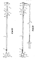
- Fig. 2 is a side view of the instrument of Fig. 1;
- Fig. 3 is a detail of Fig. 2 with the head portion in an open position;
- Fig. 4 is a perspective view of the front face of the head portion of the instrument of Figs. 1 and 2;
- Fig. 5 is a perspective view of the back face of the head portion of the instrument of Figs. 1 and 2;
- Fig. 6 is a perspective view of the trailing end of the instrument of Figs. 1 and 2;
- Fig. 7 is a sectional view corresponding to Fig. 6 with electrical wires missing;
- Fig. 8 is a side view of a second embodiment of an instrument according to the present invention;
- Fig. 9 is a front elevation of the instrument of Fig. 8;
- Fig. 10 is an enlarged view of the head portion of the instrument of Fig. 8 shown in a sectional view;
- Fig. 1 1 is a back elevation of the head portion shown in Fig. 10;
- Fig. 12 is a back elevation of a lower jaw of the head portion shown in Fig. 10;
- Fig. 13 is a plan view of the lower jaw viewed on A of Fig. 12;
- Fig. 14 is as sectional view of the lower jaw on X-X of Fig. 12;
- Fig. 15 is an end elevation of the lower jaw viewed on B on Fig. 14;
- Fig. 16 is a side elevation of a top jaw of the head portion shown in Fig. 10;
- Fig. 17 is a plan view of the top jaw viewed on A of Fig. 16;
- Fig. 18 is a back elevation of the top jaw of Fig. 16;
- Fig. 19 is an enlarged back view of the trailing end of the instrument of Fig. 9;
- Fig. 20 is a sectional side view of the plunger shown in Fig. 19; and,
- Fig. 21 is a front view of slider tube of Fig. 19.
- Referring to Figs 1 to 7 of the drawings, the instrument of this embodiment of the invention has a tubular
main shaft 1 of flexible plastics with ahead portion 2 at its leadingend 3 and aplunger 4 at itstrailing end 5. A pair of mutually insulatedelectrical wires bore 8 of themain shaft 1, one of thewires 6 connecting to a pair ofelectrodes head portion 2, theother wire 7 connecting to anelectrode sheath 11 of coiled wire on the exterior of themain shaft 1. Thewires bore 8 at thetrailing end 5 through a small bite (not shown), this end being encircled by a tube ofplastic 12 withcorresponding bite 13 and its cut end being plugged with arubber stopper 14. - The
main shaft 1 is slidable within ahandle 15 of theplunger 4. Thehandle 15 consists of atube 16 coaxial with themain shaft 1 and carries a pair ofwings 17 at its base. A knottedend 18 of acord 19, which is carried alongside thewires bore 8 of themain shaft 1, is affixed to thehandle 15, protruding through a key-hole-shaped aperture 20 in thehandle 15 and acorresponding slot 21 in themain shaft 1. - The base of the
head portion 2 has acylindrical mould 22 which receives the leadingend 3 of themain shaft 1. Thecord 19 emerges through acircular aperture 23 at the top of thecylindrical mould 22 and attaches to atop jaw 24 of thehead portion 2. Thearcuate electrodes top jaw 24 and abottom jaw 25 of thehead portion 2 respectively, protruding throughsmall perforations 26 in arubber membrane 27 that is glued taut over a face of thehead portion 2. The top andbottom jaws hinge 28. - In use, the
wires electrodes head member 2 rest against the scalp of the foetus. Thehandle 15 is slid down over the trailingend 5 of themain shaft 1, hence pulling thecord 19 which results in thetop jaw 24 pivoting relative to thebottom jaw 25 against the resistance of therubber membrane 27. Themembrane 27 is then in a stretched condition. With thehead portion 2 pressed against the foetal scalp theplunger 4 is released and the elasticity of therubber membrane 27 pulls thejaws electrodes electrode sheath 11 is constantly in contact with the mother; hence, as soon as theelectrodes - To remove the instrument, the
handle 15 is once more moved along themain shaft 1, such that thecord 19 pulls open thejaws electrodes head portion 2 is gently lifted from the baby's scalp before thehandle 15 is once more released, causing thejaws electrode 30 in the form of an generally semi-circular needle. Theelectrode 30 is attached to thetop jaw 24 and emerges from themembrane 27 at only one point, this beingperforation 26. In the closed jaw position, thetip 31 of theelectrode 30 lies adjacent themembrane 27 and, in this way, thetip 31 is shielded during insertion of the instrument into a vagina. - The
top jaw 24 is almost entirely encapsulated in an arch-shapedmoulded extension 32 of thelower jaw 25, such that thehinge 28 of thejaws extensions 33 of thelower jaw 25 enclose thecylindrical mould 22 holding themain shaft 1 and shield theemergent cord 19 and the back of thetop jaw 24. Theextensions 33 are serrated to give a good grip for the operator's fingers when the instrument is in use. - The
main shaft 1 terminates at itstrailing end 5 in aplunger 4 comprising ahandle 15 and aninternal slider tube 34, theslider tube 34 being fitted as an extension to themain shaft 1 and being slidable within thehandle 15. Thecord 19 extends from thebore 8 of themain shaft 1, through aslot 35 in theslider tube 34, to a funnel-shape aperture 36 in the side of thehandle 15 wherein theknotted end 18 of thecord 19 is retained. In operation, as for the first embodiment, thehandle 15 is moved along themain shaft 1 to open or close the hingedly connectedjaws - Modifications and improvements may be made without departing from the scope of the invention.
Claims (6)
Applications Claiming Priority (2)
| Application Number | Priority Date | Filing Date | Title |
|---|---|---|---|
| GB8613687 | 1986-06-05 | ||
| GB868613687A GB8613687D0 (en) | 1986-06-05 | 1986-06-05 | Instrument for monitoring foetal heart rate |
Publications (2)
| Publication Number | Publication Date |
|---|---|
| EP0248627A2 true EP0248627A2 (en) | 1987-12-09 |
| EP0248627A3 EP0248627A3 (en) | 1988-04-20 |
Family
ID=10598990
Family Applications (1)
| Application Number | Title | Priority Date | Filing Date |
|---|---|---|---|
| EP87304839A Withdrawn EP0248627A3 (en) | 1986-06-05 | 1987-06-01 | Instrument for monitoring foetal heart rate |
Country Status (2)
| Country | Link |
|---|---|
| EP (1) | EP0248627A3 (en) |
| GB (1) | GB8613687D0 (en) |
Cited By (3)
| Publication number | Priority date | Publication date | Assignee | Title |
|---|---|---|---|---|
| EP0377432A1 (en) * | 1989-01-05 | 1990-07-11 | Abbott Laboratories | Tool for placement of a monitoring probe in the scalp of a fetus |
| US5474065A (en) * | 1994-04-04 | 1995-12-12 | Graphic Controls Corporation | Non-invasive fetal probe |
| US5833622A (en) * | 1994-04-04 | 1998-11-10 | Graphic Controls Corporation | Non-invasive fetal probe having improved mechanical and electrical properties |
Citations (4)
| Publication number | Priority date | Publication date | Assignee | Title |
|---|---|---|---|---|
| GB1523263A (en) * | 1977-02-09 | 1978-08-31 | Copeland J | Foetal scalp electrodes |
| EP0004510A1 (en) * | 1978-03-23 | 1979-10-03 | ANVAR Agence Nationale de Valorisation de la Recherche | Measuring device for physiological signals to be placed on or inside a part of the body |
| EP0007702A1 (en) * | 1978-06-21 | 1980-02-06 | Theodore Chester Neward | Apparatus for use in physiological monitoring |
| US4304453A (en) * | 1979-10-26 | 1981-12-08 | Harco Electronics Limited | Articulable article clamp |
-
1986
- 1986-06-05 GB GB868613687A patent/GB8613687D0/en active Pending
-
1987
- 1987-06-01 EP EP87304839A patent/EP0248627A3/en not_active Withdrawn
Patent Citations (4)
| Publication number | Priority date | Publication date | Assignee | Title |
|---|---|---|---|---|
| GB1523263A (en) * | 1977-02-09 | 1978-08-31 | Copeland J | Foetal scalp electrodes |
| EP0004510A1 (en) * | 1978-03-23 | 1979-10-03 | ANVAR Agence Nationale de Valorisation de la Recherche | Measuring device for physiological signals to be placed on or inside a part of the body |
| EP0007702A1 (en) * | 1978-06-21 | 1980-02-06 | Theodore Chester Neward | Apparatus for use in physiological monitoring |
| US4304453A (en) * | 1979-10-26 | 1981-12-08 | Harco Electronics Limited | Articulable article clamp |
Non-Patent Citations (1)
| Title |
|---|
| AMERICAN JOURNAL OF OBSTETRICS AND GYNECOLOGY, vol. 86, no. 6, 15th July 1963, pages 772-784; E.H. HON: "Instrumentation of fetal heart rate and fetal electrocardiography" * |
Cited By (4)
| Publication number | Priority date | Publication date | Assignee | Title |
|---|---|---|---|---|
| EP0377432A1 (en) * | 1989-01-05 | 1990-07-11 | Abbott Laboratories | Tool for placement of a monitoring probe in the scalp of a fetus |
| US5474065A (en) * | 1994-04-04 | 1995-12-12 | Graphic Controls Corporation | Non-invasive fetal probe |
| US5665477A (en) * | 1994-04-04 | 1997-09-09 | Graphic Controls Corporation | Hydrogel adhesive for attaching medical device to patient |
| US5833622A (en) * | 1994-04-04 | 1998-11-10 | Graphic Controls Corporation | Non-invasive fetal probe having improved mechanical and electrical properties |
Also Published As
| Publication number | Publication date |
|---|---|
| GB8613687D0 (en) | 1986-07-09 |
| EP0248627A3 (en) | 1988-04-20 |
Similar Documents
| Publication | Publication Date | Title |
|---|---|---|
| US5632274A (en) | Connection arrangement for monitoring fetal heart rate | |
| US3827428A (en) | Bipolar electrode structure for monitoring fetal heartbeat and the like | |
| EP0099077B1 (en) | Fetal electrode apparatus | |
| US4076028A (en) | Forceps spacing device | |
| US4702256A (en) | Electrical connector for a disposable electrode | |
| US5944562A (en) | Clasp structure for biomedical electrodes | |
| US6363272B1 (en) | Connector for fetal probe | |
| US3533403A (en) | Combination heart catheter and electrode | |
| US3463152A (en) | Catheter placement unit | |
| US6973341B2 (en) | Noninvasive, intrauterine fetal ECG strip electrode | |
| US4072388A (en) | Anti-snag device for electrode lead clips | |
| US3580242A (en) | Fetal scalp electrode unit | |
| EP0393279A2 (en) | Polypectome snare with bipolar electrodes | |
| JPH09206285A (en) | Catheter set that can be connected to ecg | |
| US2894512A (en) | Epilation device | |
| US4220387A (en) | Medical clip | |
| US3989038A (en) | Fetal electrode and biopsy device | |
| US4913151A (en) | Tool for placement of a monitoring probe in the scalp of a fetus | |
| US4254764A (en) | Clip electrode | |
| US3800784A (en) | Medical instrument for examining a fetus during delivery | |
| EP0248627A2 (en) | Instrument for monitoring foetal heart rate | |
| US5413590A (en) | Skin treatment device | |
| US3910271A (en) | Method of making a bipolar electrode structure | |
| US5377677A (en) | Packaging system for a fetal electrode | |
| US3986497A (en) | Electrode wire clamp |
Legal Events
| Date | Code | Title | Description |
|---|---|---|---|
| PUAI | Public reference made under article 153(3) epc to a published international application that has entered the european phase |
Free format text: ORIGINAL CODE: 0009012 |
|
| AK | Designated contracting states |
Kind code of ref document: A2 Designated state(s): DE FR GB IT |
|
| PUAL | Search report despatched |
Free format text: ORIGINAL CODE: 0009013 |
|
| AK | Designated contracting states |
Kind code of ref document: A3 Designated state(s): DE FR GB IT |
|
| STAA | Information on the status of an ep patent application or granted ep patent |
Free format text: STATUS: THE APPLICATION IS DEEMED TO BE WITHDRAWN |
|
| 18D | Application deemed to be withdrawn |
Effective date: 19881021 |
|
| RIN1 | Information on inventor provided before grant (corrected) |
Inventor name: MEREDITH, HADYN GWYN Inventor name: FULLER, PETER BRIAN |