EP0249948A2 - Image information processing apparatus - Google Patents
Image information processing apparatus Download PDFInfo
- Publication number
- EP0249948A2 EP0249948A2 EP87108669A EP87108669A EP0249948A2 EP 0249948 A2 EP0249948 A2 EP 0249948A2 EP 87108669 A EP87108669 A EP 87108669A EP 87108669 A EP87108669 A EP 87108669A EP 0249948 A2 EP0249948 A2 EP 0249948A2
- Authority
- EP
- European Patent Office
- Prior art keywords
- image information
- pixel density
- pixels
- pixel
- terized
- Prior art date
- Legal status (The legal status is an assumption and is not a legal conclusion. Google has not performed a legal analysis and makes no representation as to the accuracy of the status listed.)
- Granted
Links
Images

Classifications
-
- H—ELECTRICITY
- H04—ELECTRIC COMMUNICATION TECHNIQUE
- H04N—PICTORIAL COMMUNICATION, e.g. TELEVISION
- H04N1/00—Scanning, transmission or reproduction of documents or the like, e.g. facsimile transmission; Details thereof
- H04N1/32—Circuits or arrangements for control or supervision between transmitter and receiver or between image input and image output device, e.g. between a still-image camera and its memory or between a still-image camera and a printer device
- H04N1/32101—Display, printing, storage or transmission of additional information, e.g. ID code, date and time or title
- H04N1/32106—Display, printing, storage or transmission of additional information, e.g. ID code, date and time or title separate from the image data, e.g. in a different computer file
- H04N1/32122—Display, printing, storage or transmission of additional information, e.g. ID code, date and time or title separate from the image data, e.g. in a different computer file in a separate device, e.g. in a memory or on a display separate from image data
-
- H—ELECTRICITY
- H04—ELECTRIC COMMUNICATION TECHNIQUE
- H04N—PICTORIAL COMMUNICATION, e.g. TELEVISION
- H04N1/00—Scanning, transmission or reproduction of documents or the like, e.g. facsimile transmission; Details thereof
- H04N1/40—Picture signal circuits
- H04N1/40068—Modification of image resolution, i.e. determining the values of picture elements at new relative positions
-
- H—ELECTRICITY
- H04—ELECTRIC COMMUNICATION TECHNIQUE
- H04N—PICTORIAL COMMUNICATION, e.g. TELEVISION
- H04N2201/00—Indexing scheme relating to scanning, transmission or reproduction of documents or the like, and to details thereof
- H04N2201/32—Circuits or arrangements for control or supervision between transmitter and receiver or between image input and image output device, e.g. between a still-image camera and its memory or between a still-image camera and a printer device
- H04N2201/3201—Display, printing, storage or transmission of additional information, e.g. ID code, date and time or title
- H04N2201/3225—Display, printing, storage or transmission of additional information, e.g. ID code, date and time or title of data relating to an image, a page or a document
- H04N2201/3243—Display, printing, storage or transmission of additional information, e.g. ID code, date and time or title of data relating to an image, a page or a document of type information, e.g. handwritten or text document
-
- H—ELECTRICITY
- H04—ELECTRIC COMMUNICATION TECHNIQUE
- H04N—PICTORIAL COMMUNICATION, e.g. TELEVISION
- H04N2201/00—Indexing scheme relating to scanning, transmission or reproduction of documents or the like, and to details thereof
- H04N2201/32—Circuits or arrangements for control or supervision between transmitter and receiver or between image input and image output device, e.g. between a still-image camera and its memory or between a still-image camera and a printer device
- H04N2201/3201—Display, printing, storage or transmission of additional information, e.g. ID code, date and time or title
- H04N2201/3225—Display, printing, storage or transmission of additional information, e.g. ID code, date and time or title of data relating to an image, a page or a document
- H04N2201/3254—Orientation, e.g. landscape or portrait; Location or order of the image data, e.g. in memory
Definitions
- the present invention relates to an image information processing apparatus, such as an electronic filing apparatus which stores a vast amount of image information and performs retrieval or edition of the stored image information.
- an electronic filing apparatus for use as an image information processing apparatus to process a vast amount of image information such as documents.
- This electronic filing apparatus reads a vast amount of such image information by means of optical, two-dimensional scanning, and sequentially stores the image information on, for example, an optical disk, and stores retrieval data for each item of the image information on, for example, a magnetic disk.
- the electronic filing apparatus retrieves the image information stored in the optical disk and provides a visual output of the information, by means of an output device such as a cathode ray tube display device (hereinafter referred to as CRT display device) or a recording device.
- CTR display device cathode ray tube display device
- this type of filing apparatus can be applied to a system which comprises a plurality of terminals for performing inputting, retrieval, and editing of image information, all of which are coupled on-line to an electronic filing apparatus (host machine) which stores all the image information processed by the terminals, or to a system in which host machines located in separate departments are coupled on-line to one another, so that one host machine can retrieve image information stored in another machine, when needed.
- host machine electronic filing apparatus
- Conventional terminals and electronic filing apparatuses are coupled to input/output devices for image information, such as a scanner, a facsimile, and a printer, which have a pixel density (or resolution) of 8 pixels/mm ⁇ 7.7 pixels/mm (main-scanning direction ⁇ sub-scanning direction) or l8 pixels/mm ⁇ l5.4 pixels/mm (main-scanning direction ⁇ sub-scanning direction).
- the electronic filing apparatus is designed to process only image information with 8 pixels/mm ⁇ 7.7 pixels/mm or l6 pixels/mm ⁇ l5.4 pixels/mm, which matches the pixel density of the input/output devices.
- image information may have various types of pixel densities: they may be reproduced in the form of pixels/mm or pixels/inch, or may differ in the number of pixels per mm or inch, for example, 8 pixels/mm, l6 pixels/mm, 200 pixels/inch, or 400 pixels/inch. Therefore, it is likely that image information with different pixel densities are transferred between input/output devices with different pixel densities.
- a apparatus which stores image information with a pixel density of 8 pixels/mm ⁇ 7.7 pixels/mm is coupled on-line to another apparatus which stores image information with a pixel density of 200 pixels/inch ⁇ 200 pixels/inch.
- the output image information differs from the original (proper) image information, and is deformed such that the output image information has a reduced size for the main-scanning direction and a increased size for the sub-scanning direction than the original.
- the output image information differs from the original (proper) image information and is distorted such that the output image information has an increased size, with respect to the main-scanning direction, and a reduced size, with respect to the sub-scanning direction, than the original.
- an apparatus which is correctly displaying image information (destination pasting image) with a pixel density of, for example, 400 pixels/inch ⁇ 400 pixels/inch retrieves image information (source image) with a pixel density of l6 pixels/mm ⁇ l5.4 pixels/mm and is pasted on the destination pasting image, the image information to be pasted or the source image would be distorted on the destination pasting image.
- an object of this invention to provide an image information processing apparatus which overcomes the conventional problem of inaccurate reproduction of the original image information when image information with different pixel densities is processed simultaneously, and can accurately reproduce the original image information without distortion, even when image information with different pixel densities is involved.
- the image information processing apparatus of this invention comprises means for supplying image information of various pixel densities, means for outputting the image information supplied from said supplying means, said outputting means having a predetermined pixel density, means for storing pixel density conversion factors, and means for reading the pixel density conversion factor corresponding to pixel density of image information supplied from said supplying means and the pixel density of said outputting means from said storage means, and for converting pixel density of image information supplied from said supplying means into the pixel density of said outputting means according to said read pixel density conversion factor.
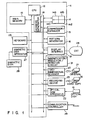
- FIG. l shows the arrangement of an electronic filing apparatus as an example of an image information processing apparatus embodying this invention.
- a main controller ll comprises a CPU (central processing unit) l2, a main memory l3, a buffer memory l4, a compressor/expander l5, a pattern generator l6, a display interface l7, and an address generator l8.
- CPU l2 controls the overall apparatus.
- Main memory l3 stores input retrieval codes, etc.
- Buffer memory l4 has a memory capacity corresponding to image information for several A4-size pages, and has memory areas l4a, l4b, l4c, and l4d provided for a maximum of four windows which may be opened on a CRT display device 24, respectively.
- Compressor/expander l5 compresses image information (or decreases its redundancy) and expands it (or restores the decreased redundancy to the original one).
- Pattern generator l6 stores pattern data such as characters and symbols.
- Display interface l7 executes display control of CRT display device 24.
- Address generator l8 controls access to display memories (not shown) provided in buffer memory l4 and display interface l7.
- Main controller ll is coupled to a scanner 20, an optical disk apparatus 22, a keyboard 23, CRT display device 24 as an output device, a recording device also as an output device, a magnetic disk apparatus 27, a communication controller 29, and a magnification/reduction/rotation circuit 3l as a conversion unit.
- Scanner 20 may be a two-dimensional scanner, which two-dimensionally scans an original (document) 2l by means of a laser beam, to provide an electric signal corresponding to the image information on the original.
- Optical disk apparatus 22 sequentially stores or writes, onto an optical disk l9, image information which is scanned by two-dimensional scanner 20 and supplied via main controller ll, or reads out image information from optical disk l9.
- Keyboard 23 is for entering a specific retrieval code for each image information and various operation commands.
- CRT display device 24 displays image information which has been scanned by two-dimensional scanner 20 and supplied via main controller ll, or image information which has been read out from optical disk apparatus 22 and then supplied via main controller ll.
- CRT display device 24 and display interface l7 of main controller ll constitute an image information display apparatus.
- CRT display device 24 is capable of simultaneously displaying four documents (image information through a maximum of four windows, so that magnification, reduction, rotation, and scrolling of image information can be carried out for each window.
- Recording device 25 provides a hard copy 26 of image information which is supplied via controller ll, for example, after it is scanned by two-dimensional scanner 20 or after it is read out from optical disk apparatus 22.
- Magnetic disk apparatus 27 stores a retrieval code and retrieval data, entered via keyboard 23, on a magnetic disk 28 for each item of image information.
- the retrieval data includes an image information number or a part number ("part” means a partial image, i.e., part of a document as a mass of image) for each item of image information associated with the retrieval code, the size, direction, pixel density, and compressing mode of the image information associated with the image information number or part number, and a memory address on optical disk l9 where this image information is stored.
- Communication controller 29 is coupled via a communication line to the communication controller of each terminal (not shown) or to another electronic filing apparatus, and transmits image information requested for retrieval or edition to the requesting terminal or electronic filing apparatus.
- Communication controller 29 also receives a process request and transfers stored image information and its retrieval code or the retrieval code for retrieving image information to be edited, to main controller ll.
- Magnification/reduction/rotation circuit 3l executes magnification, reduction, and rotation of image information, and when the output of image information is provided by CRT display device 24 or recording device 25 (both serving as an output device), this circuit also converts the pixel density of the image information according to the conversion factor which is associated with the pixel density of the image information, and the pixel density of the selected output device or the pixel density of the destination image subjected to an image editing process.
- CPU l2 performs on-line image information retrieval using the data (retrieval code) which corresponds to a requested retrieval or edition and is supplied from communication controller 29.
- CPU l2 finds the desired image information, it transmits an "image-found signal” and the image information to the requesting terminal or electronic filing apparatus via communication controller 29.
- CPU l2 transmits an "image-not-found signal" to the requesting unit.
- CPU l2 causes optical disk apparatus 22 to store the image information onto optical disk l9.
- CPU l2 also executes an operation according to a process request entered via keyboard 23 by an operator.
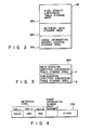
- magnetic disk 28 includes a pixel density conversion table storage area 28a, a retrieval data storage area 28b, and an image information memory address storage area 28c.
- Pixel density conversion table storage area 28a contains conversion factors which are associated with the pixel density of image information and the pixel densities of output devices, such as CRT display device 24 and recording device 25, or the pixel density of a destination image in an image editing operation.
- Retrieval data storage area 28b contains a retrieval code and the image information number of the image information associated with this code, or the part number of partial image information (i.e., part image information) associated with the code for each optical disk.
- Image information memory address storage area 28c stores a memory address of each item of image information for every image information number or part number.
- pixel density conversion table storage area 28a includes a main-scanning direction conversion table storage area A and a sub-scanning direction conversion table storage area B.
- Main-scanning direction conversion table storage area A stores conversion factors for converting a pixel density with respect to the main-scanning (vertical) direction
- sub-scanning direction conversion table storage area B stores conversion factors with respect to the sub-scanning (horizontal) direction.
- main-scanning direction conversion table storage area A stores conversion factors which are associated with the pixel density of image information (conversion source or transfer source) in the main-scanning direction and the pixel densities of output devices, such as CRT display device 24 and recording device 25 (conversion destination) or the pixel density of a destination image for an image editing operation (see Table l below).
- conversion factors which are associated with the pixel density of image information (conversion source or transfer source) in the main-scanning direction and the pixel densities of output devices, such as CRT display device 24 and recording device 25 (conversion destination) or the pixel density of a destination image for an image editing operation (see Table l below).
- the source image information is converted using a conversion factor of 2.00, 0.98, or l.97, respectively.
- image information with a pixel density of l6 pixels/mm as destination image information with a pixel density of 8 pixels/mm, 200 pixels/inch, or 400 pixels/inch
- the source image information is converted using a conversion factor of 0.50, 0.49, or 0.98, respectively.
- image information with a pixel density of 200 pixels/inch or 400 pixels/inch is converted so as to have an appropriate pixel density, by use of Table l.
- Sub-scanning direction conversion table storage area B stores conversion factors which are associated with the pixel density of image information (conversion source or transfer source) in the sub-scanning direction and the pixel densities of output devices, such as CRT display device 24 and recording device 25 (conversion destination) or the pixel density of a destination image for an image editing operation (see Table 2 below).
- the source image information is converted using a conversion factor of 0.98, l.02, l.96, 2.03, or 2.00, respectively.
- image information with a pixel density of 400 pixels/inch as destination image information with a pixel density of 7.7 pixels/mm, 8 pixels/mm, l5.4 pixels/mm, l6 pixels/mm, or 200 pixels/inch
- the source image information is converted using a conversion factor of 0.49, 0.5l, 0.98, l.02, or 0.50, respectively.
- image information with a pixel density of 7.7 pixels/mm, 8 pixels/mm, l5.4 pixels/mm, or l6 pixels/mm is converted so as to have an appropriate pixel density, by use of Table 2.
- retrieval data storage area 28b stores a retrieval code including a plurality of retrieval keys, and an image information number (direct number), which is a specific number for each item of image information, or a part number (direct number), which is a specific number for each part image information.
- image information memory address storage area 28c stores a memory address for each item of image information which includes a size S of the image information associated with the image information number (or part number), a direction P which indicates whether the image information is written vertically (V) or horizontally (H), a pixel density D1 of the image information, with respect to the main-scanning direction, a pixel density D2 of the image information, with respect to the sub-scanning direction, an image information leading address ADR from, which the image information is stored, a compressing mode MR/MH which indicates whether the image information is compressed in the MR (Modified Read Coding) mode or the MH (Modified Hoffman Coding) mode, and a block number V indicating the amount (block size) of the stored image information.
- the electronic filing apparatus having output devices such as CRT display device 24 and recording device 25, which have a pixel density of 200 pixels/inch ⁇ 200 pixels/inch, retrieves image information from optical disk l9 which stores image information with various pixel densities.
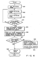
- a retrieval mode is set via keyboard 23 (step 60l) and a retrieval code is entered thereby (step 602).
- CPU l2 compares the retrieval code with retrieval codes stored in magnetic disk 28, to detect whether or not the entered code coincides with a stored code (steps 603 and 604).
- CPU l2 also supplies image information (compressed information) for each scanning line, from optical disk apparatus 22 to compressor/expander l5, where the compressed information is restored to its original form, using MR or MH inverse conversion, and then supplies the original image information to page buffer l4. Then, CPU l2 reads out the pixel densities D1 and D2 of the read-out image information from image information memory address storage area 28c, and determines whether or not the read-out pixel densities coincide with those of CRT display device 24 and recording device 25 (step 607).
- CPU l2 refers to pixel density conversion table storage area 28a and reads out the appropriate conversion factors with respect to the main-scanning and sub-scanning directions (step 609). That is, the conversion factor for the pixel density with respect to the main-scanning direction of the output devices, such as recording device 25 (conversion destination), is read out from main-scanning direction conversion table storage area A, while the conversion factor for the pixel density with respect to the sub-scanning direction is read out from sub-scanning direction conversion table storage area B.
- CPU l2 refers to pixel density conversion table storage area 28a, and reads out therefrom the conversion factors of 0.98, with respect to the main-scanning direction, and l.02, with respect to the sub-scanning direction, Which are associated with the pixel density (conversion destination) of 200 pixels/inch ⁇ 200 pixels/inch.
- the pixel density for the main-scanning direction is converted from 8 pixels/mm to 200 pixels/inch, while the pixel density with respect to the sub-scanning direction is converted from 7.7 pixels/mm to 200 pixels/inch.
- CPU l2 refers to pixel density conversion table storage area 28a, and reads out therefrom the conversion factors of 0.50 with respect to the main-scanning direction, and 0.50, with respect to the sub-scanning direction, which are associated with the pixel density (conversion destination) of 200 pixels/inch ⁇ 200 pixels/inch (step 609).
- the image information having the thus-converted pixel density is sequentially supplied to page buffer l4.
- CPU l2 causes display interface l7 to display the image information on CRT display device 24, or causes recording device 25 to provide a hard copy 26 of the image information (step 608).
- the electronic filing apparatus having output devices such as CRT display device 24 and recording device 25, which have a pixel density of l6 pixels/mm ⁇ l5.4 pixels/mm, retrieves image information from optical disk l9, which stores image information having various pixel densities.
- a retrieval mode is set via keyboard 23 and a retrieval code is entered thereby.
- CPU l2 compares the retrieval code with retrieval codes stored in magnetic disk 28, to detect whether or not the entered code coincides with a stored code.
- CPU l2 causes optical disk apparatus 22 to reproduce the image information on optical disk l9, from the address corresponding to the image information leading address ADR of the read-out memory address.
- CPU l2 also supplies image information (compressed information for each scanning line from optical disk apparatus 22 to compressor/expander l5, where the compressed information is restored to its original form, using MR or MH inverse conversion, and then supplies the original image information to page buffer l4.
- CPU l2 reads out the pixel densities D1 and D2 of the read-out image information from image information memory address storage area 28c, and determines whether or not the read-out pixel densities coincide with those of CRT display device 24 and recording device 25.
- CPU l2 refers to pixel density conversion table storage area 28a, and reads out the appropriate conversion factor for the pixel density (conversion destination), with respect to the main-scanning direction, from main-scanning direction conversion table storage area A, and reads out the appropriate conversion factor for the pixel density (conversion destination), with respect to the sub-scanning direction, from sub-scanning direction conversion table storage area B.
- CPU l2 refers to pixel density conversion table storage area 28a, and reads out therefrom the conversion factors of 2.03, with respect to the main-scanning direction, and l.96, with respect to the sub-scanning direction, which are associated with the pixel density (conversion destination) of l6 pixels/mm ⁇ l5.4 pixels/mm.
- CPU l2 refers to pixel density conversion table storage area 28a, and reads out therefrom the conversion factors of 2.00, with respect to the main-scanning direction, and 2.00, with respect to the sub-scanning direction, which are associated with the pixel density (conversion destination) of l6 pixels/mm ⁇ l5.4 pixels/mm.
- the image information having the thus-converted pixel density is sequentially supplied to page buffer l4.
- CPU l2 causes display interface l7 to display the image information on CRT display device 24, or causes recording device 25 to provide a hard copy 26 of the image information.
- the pixel density of the output device for providing the output of image information differs from that of attained image information
- the pixel density of the attained image information is converted so as to coincide with that of the output device. This ensures the proper transferring of image information and thus provides accurate reproduction of the original image information, even when the pixel density of the original image information differs from that of the output device.
- image information is retrieved from optical disk apparatus l9.
- this invention can apply to a system in which electronic filing apparatuses storing image information having different pixel densities are coupled to one another via a LAN, and the image information of one apparatus is retrieved on-line by another apparatus.
- the pixel density of the image information obtained via communication controller 29 has to be converted according to the pixel density of the retrieving apparatus.
- an electronic filing apparatus in which image information having a pixel density of 8 pixels/mm ⁇ 7.7 pixels/mm is coupled via a LAN to another electronic filing apparatus which contains image information having a pixel density of 200 pixels/inch ⁇ 200 pixels/inch.
- the conversion factors of 0.98 and l.02 associated with the the pixel density of the conversion destination, are read out from pixel density conversion table storage area 28a, in advance.
- the pixel density with respect to the main-scanning direction of the image information transmitted via communication controller 29 is converted from 8 pixels/mm to 200 pixels/inch, using the former conversion factor of 0.98, and the pixel density with respect to the sub-scanning direction is converted from 7.7 pixels/mm to 200 pixels/inch, using the latter conversion factor of l.02.
- image information having a pixel density of 8 pixels/mm ⁇ 7.7 pixels/mm as image information having a pixel density of 200 pixels/inch ⁇ 200 pixels/inch. Therefore, even when the retrieved image information is output from the output device such as recording device 25 whose pixel density differs from that of the retrieved image information, it is possible to reproduce the original image accurately, without increasing or decreasing its size.
- part image information is retrieved for an image editing operation.
- image information having a 200 pixels/inch ⁇ 200 pixels/inch pixel density is stored in an electronic filing apparatus and that part image information having this pixel density, as well as part image information having a pixel density of 8 pixels/mm ⁇ 7.7 pixels/mm are retrieved to be edited.
- pixel density conversion table storage area 28a is referred to, and the conversion factors of 0.98, with respect to the main-scanning direction, and l.02, with respect to the sub-scanning direction, are read out therefrom so as to convert the image information with the 8 pixels/mm ⁇ 7.7 pixels/mm pixel density into image information with the 200 pixels/inch ⁇ 200 pixels/inch pixel density.
- the pixel density of 8 pixels/mm with respect to the main-scanning direction and the pixel density of 7.7 pixels/mm with respect to the sub-scanning direction are both converted to pixel density of 200 pixels/inch ⁇ 200 pixels/inch.
- the image information having the converted pixel density of 200 pixels/inch ⁇ 200 pixels/inch and that originally having the 200 pixels/inch ⁇ 200 pixels/inch are displayed on the same screen of CRT display device 24.
- the original image information can be accurately reproduced, without increasing or decreasing its size. Therefore, it is possible to edit different partial image information, such as one with a pixel density of 8 pixels/mm ⁇ 7.7 pixels/mm and another with a pixel density of 200 pixels/inch ⁇ 200 pixels/inch.
- An image editing process for pasting part image information onto a pasting image can similarly be performed. Assume that part image information having a pixel density of l6 pixels/mm ⁇ l5.4 pixels/mm is retrieved and pasted onto image information (pasting image) having a pixel density of 400 pixels/inch ⁇ 400 pixels/inch. Then, pixel density conversion table storage area 28a is referred to, and the conversion factors of 0.98, with respect to the main-scanning direction, and l.02, with respect to the sub-scanning direction are read out therefrom, so as to convert the image information with the l6 pixels/mm ⁇ l5.4 pixels/mm pixel density to image information with the 400 pixels/inch ⁇ 400 pixels/inch pixel density.
- the conversion factors with respect to the pixel densities for the main-scanning and sub-scanning directions for the pasting image (destination) are attained.
- the pixel density of l6 pixels/mm with respect to the main-scanning direction is converted into 400 pixels/inch, as is also the pixel density of l5.4 pixels/mm with respect to the sub-scanning direction.
- the image information originally having a pixel density of l6 pixels/mm ⁇ l5.4 pixels/mm can be treated as the pasting image having the pixel density of 400 pixels/inch ⁇ 400 pixels/inch. Therefore, it is possible to paste image information free of any expansion or reduction in size onto the pasting image.
- part image information is what is indicated by the image information numbers (part numbers) following "l0000l,” as is shown in Fig. 5.
- the above embodiment has been explained using the case where the pixel densities of the input/output devices or terminals coupled to main controller ll are specifically given, i.e., the pixel densities of the conversion or transfer destinations are known in advance.
- this invention can also be applied in the case where various input/output devices or terminals with different pixel densities are coupled to main controller ll and it is not known in advance which input/output device or terminal is to be used.
- a connected-device managing table such as Table 3 given later, needs to be provided in another memory area of magnetic disk 28 and used to determined which input/output device or terminal is currently coupled to main controller ll, and conversion of pixel densities of image information needs to be performed based on the conversion factors associated with the pixel density of the detected device or terminal.
- the connected-device managing table stored in magnetic disk 28 includes the name of each input/output device or terminal to be coupled to main controller ll, the sizes of paper, the direction of an image, the pixel density of each device or terminal and a flag indicating the connection status thereof, with these attributes being in association with the number of each device or terminal.
- the flag is referred to determine what pixel density the input/output device or terminal currently coupled has, and based on the determination, the pixel density of image information to be treated is converted to coincide with that of the currently-coupled device. In this manner, it is possible to treat different input/output devices, such as a scanner, a facsimile and a printer, without any problems, and prevent undesirable deformation of processed image information, thus ensuring the proper expression of the original image.
- the retrieved image information is judged to have the conventional pixel density. For example, when the pixel densities corresponding to the retrieved image information stored at its memory address are only 8 pixels/mm ⁇ 8 pixels/mm and l6 pixels/mm ⁇ l5.4 pixels/mm, it would be judged that the pixel density of the retrieved image information is either 8 pixels/mm ⁇ 7.7 pixels/mm or l6 pixels/mm ⁇ l5.4 pixels/mm.
- the conversion factor which is associated with this pixel density and the pixel density of an output device, such as CRT display device 24 or recording device 25, is read out from pixel density conversion table storage area 28a.
- the pixel density of the retrieved image information either 8 pixels/mm ⁇ 7.7 pixels/mm or l6 pixels/mm ⁇ l5.4 pixels/mm is properly converted.
- the pixel density of image information can be converted into various values to provide a proper output of the image information
- this invention provides a higher resolution and a higher flexibility to deal with image information with different pixel densities and use various input/output devices, such as a scanner, a facsimile, and a printer, which have different pixel densities. Therefore, even when an output of image information needs to be provided by an input/output device whose pixel density differs from that of the image information, the original image information would not be deformed when output.
- a magnification/reduction/rotation circuit is used to convert the pixel density; however, such conversion may be performed using software instead. This eliminates the need for specific hardware and thus makes the involved apparatus more compact and reduces its manufacturing cost.
- the pixel density conversion table, the connected-device managing table and the like are stored in a magnetic disk. However, they may be provided in main memory l3 of main controller ll or another memory device.
- image information and retrieval data are stored in separate memory devices, such as optical disk l9 and magnetic disk 28, respectively.
- the data storage is not limited to this particular type; both the image information and retrieval data may be stored in the same optical disk.
- the optical disk may be separated into an internal section as a data storage area to store the retrieval data and an outer section as an image storage area to store the image information, or vice versa, as desired.
- the aforementioned embodiment has been described to perform retrieval of image information; however, it may be modified such that image information scanned by a two-dimensional scanner (an input device) and image information scanned by another two-dimensional scanner can be processed to have the same pixel density and stored into a single optical disk.
- this invention can provide an image information processing apparatus, which is capable of properly expressing the original image information without any deformation, even when image information with different pixel densities are processed together.
Abstract
Description
- The present invention relates to an image information processing apparatus, such as an electronic filing apparatus which stores a vast amount of image information and performs retrieval or edition of the stored image information.
- Recently, an electronic filing apparatus has been developed for use as an image information processing apparatus to process a vast amount of image information such as documents. This electronic filing apparatus reads a vast amount of such image information by means of optical, two-dimensional scanning, and sequentially stores the image information on, for example, an optical disk, and stores retrieval data for each item of the image information on, for example, a magnetic disk. When the retrieval data is entered, the electronic filing apparatus retrieves the image information stored in the optical disk and provides a visual output of the information, by means of an output device such as a cathode ray tube display device (hereinafter referred to as CRT display device) or a recording device. Further, this type of filing apparatus can be applied to a system which comprises a plurality of terminals for performing inputting, retrieval, and editing of image information, all of which are coupled on-line to an electronic filing apparatus (host machine) which stores all the image information processed by the terminals, or to a system in which host machines located in separate departments are coupled on-line to one another, so that one host machine can retrieve image information stored in another machine, when needed.
- However, the pixel density of image information processed by such host machines is limited. Conventional terminals and electronic filing apparatuses are coupled to input/output devices for image information, such as a scanner, a facsimile, and a printer, which have a pixel density (or resolution) of 8 pixels/mm × 7.7 pixels/mm (main-scanning direction × sub-scanning direction) or l8 pixels/mm × l5.4 pixels/mm (main-scanning direction × sub-scanning direction). Therefore, the electronic filing apparatus is designed to process only image information with 8 pixels/mm × 7.7 pixels/mm or l6 pixels/mm × l5.4 pixels/mm, which matches the pixel density of the input/output devices.
- Some recent electronic filing apparatus are, however, designed to be coupled to input/output devices having a pixel density different from that of conventional devices, in order to process image information with new pixel densities. Accordingly, image information may have various types of pixel densities: they may be reproduced in the form of pixels/mm or pixels/inch, or may differ in the number of pixels per mm or inch, for example, 8 pixels/mm, l6 pixels/mm, 200 pixels/inch, or 400 pixels/inch. Therefore, it is likely that image information with different pixel densities are transferred between input/output devices with different pixel densities. This may happen when electronic filing apparatuses storing image information with a conventional pixel density are coupled on-line to those storing image information with a new pixel density via a LAN (local area network) to provide information retrieval between these apparatuses, or when image information stored in an optical disk with one pixel density is retrieved by another apparatus with a different pixel density.
- Suppose that a apparatus which stores image information with a pixel density of 8 pixels/mm × 7.7 pixels/mm is coupled on-line to another apparatus which stores image information with a pixel density of 200 pixels/inch × 200 pixels/inch. When the image information stored in the former apparatus is retrieved by the latter apparatus, the output image information differs from the original (proper) image information, and is deformed such that the output image information has a reduced size for the main-scanning direction and a increased size for the sub-scanning direction than the original.
- When image information stored in an optical disk with a pixel density of 200 pixels/inch × 200 pixels/inch is retrieved by an apparatus which stores image information with a pixel density of 8 pixels/mm × 7.7 pixels/mm, the output image information differs from the original (proper) image information and is distorted such that the output image information has an increased size, with respect to the main-scanning direction, and a reduced size, with respect to the sub-scanning direction, than the original. Further, when an apparatus which is correctly displaying image information (destination pasting image) with a pixel density of, for example, 400 pixels/inch × 400 pixels/inch retrieves image information (source image) with a pixel density of l6 pixels/mm × l5.4 pixels/mm and is pasted on the destination pasting image, the image information to be pasted or the source image would be distorted on the destination pasting image.
- Obviously therefore, when retrieval of image information with different pixel densities is executed by means of the prior art, the original or source image information cannot be accurately reproduced.
- With the above situation in mind, it is an object of this invention to provide an image information processing apparatus which overcomes the conventional problem of inaccurate reproduction of the original image information when image information with different pixel densities is processed simultaneously, and can accurately reproduce the original image information without distortion, even when image information with different pixel densities is involved.
- To achieve this object, the image information processing apparatus of this invention comprises means for supplying image information of various pixel densities, means for outputting the image information supplied from said supplying means, said outputting means having a predetermined pixel density, means for storing pixel density conversion factors, and means for reading the pixel density conversion factor corresponding to pixel density of image information supplied from said supplying means and the pixel density of said outputting means from said storage means, and for converting pixel density of image information supplied from said supplying means into the pixel density of said outputting means according to said read pixel density conversion factor.
- This invention can be more fully understood from the following detailed description when taken in conjunction with the accompanying drawings, in which:
- Fig. l is a schematic block diagram of an electronic filing apparatus as an example of an image information processing apparatus embodying this invention;
- Fig. 2 is a diagram used to explain the storage structure l5 of a magnetic disk shown in Fig. l;
- Fig. 3 is a diagram showing an example of the contents of the pixel density conversion table storage area shown in Fig. 2;
- Fig. 4 is a diagram showing an example of the contents of the retrieval data storage area shown in Fig. 2;
- Fig. 5 is a diagram showing an example of the image information memory address storage area shown in Fig. 2; and
- Fig. 6 is a flowchart for explaining a retrieval operation.
- An embodiment of the present invention will now be explained, in conjunction with the accompanying drawings.
- Fig. l shows the arrangement of an electronic filing apparatus as an example of an image information processing apparatus embodying this invention. A main controller ll comprises a CPU (central processing unit) l2, a main memory l3, a buffer memory l4, a compressor/expander l5, a pattern generator l6, a display interface l7, and an address generator l8. CPU l2 controls the overall apparatus. Main memory l3 stores input retrieval codes, etc. Buffer memory l4 has a memory capacity corresponding to image information for several A4-size pages, and has memory areas l4a, l4b, l4c, and l4d provided for a maximum of four windows which may be opened on a
CRT display device 24, respectively. - Compressor/expander l5 compresses image information (or decreases its redundancy) and expands it (or restores the decreased redundancy to the original one). Pattern generator l6 stores pattern data such as characters and symbols. Display interface l7 executes display control of
CRT display device 24. Address generator l8 controls access to display memories (not shown) provided in buffer memory l4 and display interface l7. - Main controller ll is coupled to a
scanner 20, anoptical disk apparatus 22, akeyboard 23,CRT display device 24 as an output device, a recording device also as an output device, amagnetic disk apparatus 27, acommunication controller 29, and a magnification/reduction/rotation circuit 3l as a conversion unit.Scanner 20 may be a two-dimensional scanner, which two-dimensionally scans an original (document) 2l by means of a laser beam, to provide an electric signal corresponding to the image information on the original.Optical disk apparatus 22 sequentially stores or writes, onto an optical disk l9, image information which is scanned by two-dimensional scanner 20 and supplied via main controller ll, or reads out image information from optical disk l9.Keyboard 23 is for entering a specific retrieval code for each image information and various operation commands. -
CRT display device 24 displays image information which has been scanned by two-dimensional scanner 20 and supplied via main controller ll, or image information which has been read out fromoptical disk apparatus 22 and then supplied via main controller ll. In a broader sense,CRT display device 24 and display interface l7 of main controller ll constitute an image information display apparatus.CRT display device 24 is capable of simultaneously displaying four documents (image information through a maximum of four windows, so that magnification, reduction, rotation, and scrolling of image information can be carried out for each window.Recording device 25 provides ahard copy 26 of image information which is supplied via controller ll, for example, after it is scanned by two-dimensional scanner 20 or after it is read out fromoptical disk apparatus 22. -
Magnetic disk apparatus 27 stores a retrieval code and retrieval data, entered viakeyboard 23, on amagnetic disk 28 for each item of image information. The retrieval data includes an image information number or a part number ("part" means a partial image, i.e., part of a document as a mass of image) for each item of image information associated with the retrieval code, the size, direction, pixel density, and compressing mode of the image information associated with the image information number or part number, and a memory address on optical disk l9 where this image information is stored. -
Communication controller 29 is coupled via a communication line to the communication controller of each terminal (not shown) or to another electronic filing apparatus, and transmits image information requested for retrieval or edition to the requesting terminal or electronic filing apparatus.Communication controller 29 also receives a process request and transfers stored image information and its retrieval code or the retrieval code for retrieving image information to be edited, to main controller ll. - Magnification/reduction/rotation circuit 3l executes magnification, reduction, and rotation of image information, and when the output of image information is provided by
CRT display device 24 or recording device 25 (both serving as an output device), this circuit also converts the pixel density of the image information according to the conversion factor which is associated with the pixel density of the image information, and the pixel density of the selected output device or the pixel density of the destination image subjected to an image editing process. - CPU l2 performs on-line image information retrieval using the data (retrieval code) which corresponds to a requested retrieval or edition and is supplied from
communication controller 29. When CPU l2 finds the desired image information, it transmits an "image-found signal" and the image information to the requesting terminal or electronic filing apparatus viacommunication controller 29. When the desired image information is not found, CPU l2 transmits an "image-not-found signal" to the requesting unit. - In accordance with the image information and retrieval code from
communication controller 29, CPU l2 causesoptical disk apparatus 22 to store the image information onto optical disk l9. CPU l2 also executes an operation according to a process request entered viakeyboard 23 by an operator. - As is shown in Fig. 2,
magnetic disk 28 includes a pixel density conversion table storage area 28a, a retrievaldata storage area 28b, and an image information memory address storage area 28c. Pixel density conversion table storage area 28a contains conversion factors which are associated with the pixel density of image information and the pixel densities of output devices, such asCRT display device 24 andrecording device 25, or the pixel density of a destination image in an image editing operation. Retrievaldata storage area 28b contains a retrieval code and the image information number of the image information associated with this code, or the part number of partial image information (i.e., part image information) associated with the code for each optical disk. Image information memory address storage area 28c stores a memory address of each item of image information for every image information number or part number. - As is shown in Fig. 3, pixel density conversion table storage area 28a includes a main-scanning direction conversion table storage area A and a sub-scanning direction conversion table storage area B. Main-scanning direction conversion table storage area A stores conversion factors for converting a pixel density with respect to the main-scanning (vertical) direction, while sub-scanning direction conversion table storage area B stores conversion factors with respect to the sub-scanning (horizontal) direction. More specifically, main-scanning direction conversion table storage area A stores conversion factors which are associated with the pixel density of image information (conversion source or transfer source) in the main-scanning direction and the pixel densities of output devices, such as
CRT display device 24 and recording device 25 (conversion destination) or the pixel density of a destination image for an image editing operation (see Table l below). For example, to express image information with a pixel density of 8 pixels/mm conversion source or transfer source) as image information with a pixel density of l6 pixels/mm, 200 pixels/inch, or 400 pixels/inch (conversion destination or transfer destination), the source image information is converted using a conversion factor of 2.00, 0.98, or l.97, respectively. To express image information with a pixel density of l6 pixels/mm as destination image information with a pixel density of 8 pixels/mm, 200 pixels/inch, or 400 pixels/inch, the source image information is converted using a conversion factor of 0.50, 0.49, or 0.98, respectively. Similarly, image information with a pixel density of 200 pixels/inch or 400 pixels/inch is converted so as to have an appropriate pixel density, by use of Table l.
- Sub-scanning direction conversion table storage area B stores conversion factors which are associated with the pixel density of image information (conversion source or transfer source) in the sub-scanning direction and the pixel densities of output devices, such as
CRT display device 24 and recording device 25 (conversion destination) or the pixel density of a destination image for an image editing operation (see Table 2 below). For example, to express image information with a pixel density of 200 pixels/inch as image information with a pixel density of 7.7 pixels/mm, 8 pixels/mm, l5.4 pixels/mm, l6 pixels/mm, or 400 pixels/inch, the source image information is converted using a conversion factor of 0.98, l.02, l.96, 2.03, or 2.00, respectively. To express image information with a pixel density of 400 pixels/inch as destination image information with a pixel density of 7.7 pixels/mm, 8 pixels/mm, l5.4 pixels/mm, l6 pixels/mm, or 200 pixels/inch, the source image information is converted using a conversion factor of 0.49, 0.5l, 0.98, l.02, or 0.50, respectively. Similarly, image information with a pixel density of 7.7 pixels/mm, 8 pixels/mm, l5.4 pixels/mm, or l6 pixels/mm is converted so as to have an appropriate pixel density, by use of Table 2.
- As is shown in Fig. 4, retrieval
data storage area 28b stores a retrieval code including a plurality of retrieval keys, and an image information number (direct number), which is a specific number for each item of image information, or a part number (direct number), which is a specific number for each part image information. - As is shown in Fig. 5, image information memory address storage area 28c stores a memory address for each item of image information which includes a size S of the image information associated with the image information number (or part number), a direction P which indicates whether the image information is written vertically (V) or horizontally (H), a pixel density D₁ of the image information, with respect to the main-scanning direction, a pixel density D₂ of the image information, with respect to the sub-scanning direction, an image information leading address ADR from, which the image information is stored, a compressing mode MR/MH which indicates whether the image information is compressed in the MR (Modified Read Coding) mode or the MH (Modified Hoffman Coding) mode, and a block number V indicating the amount (block size) of the stored image information.
- The operation of the electronic filing apparatus with the aforementioned arrangement will now be explained, with reference to the flowchart of Fig. 6.
- To begin with, a case is explained in which the electronic filing apparatus having output devices such as
CRT display device 24 andrecording device 25, which have a pixel density of 200 pixels/inch × 200 pixels/inch, retrieves image information from optical disk l9 which stores image information with various pixel densities. Suppose now that a retrieval mode is set via keyboard 23 (step 60l) and a retrieval code is entered thereby (step 602). Then, CPU l2 compares the retrieval code with retrieval codes stored inmagnetic disk 28, to detect whether or not the entered code coincides with a stored code (steps 603 and 604). When a coincidence between codes is detected, the image information number (part number) associated with that code is read out from retrievaldata storage area 28b, and the memory address associated with the image information number (part number) is read out from image information memory address storage area 28c (step 805). As a result, CPU l2 causesoptical disk apparatus 22 to reproduce the image information on optical disk l9, from the address corresponding to the image information leading address ADR of the read-out memory address (step 606). CPU l2 also supplies image information (compressed information) for each scanning line, fromoptical disk apparatus 22 to compressor/expander l5, where the compressed information is restored to its original form, using MR or MH inverse conversion, and then supplies the original image information to page buffer l4. Then, CPU l2 reads out the pixel densities D₁ and D₂ of the read-out image information from image information memory address storage area 28c, and determines whether or not the read-out pixel densities coincide with those ofCRT display device 24 and recording device 25 (step 607). - When the determination is affirmative, i.e., when the pixel density of the obtained image information is 200 pixels/inch × 200 pixels/inch, no pixel-density conversion is performed, and all of the reproduced image information for one page is stored in page buffer l4. When the image information for one page is stored in buffer memory l4, CPU l2 causes display interface l7 to display the image information on
CRT display device 24, or causesrecording device 25 to provide ahard copy 26 of the image information (step 608). - When the pixel density of the attained image information does not coincide with those of
CRT display device 24 andrecording device 25, CPU l2 refers to pixel density conversion table storage area 28a and reads out the appropriate conversion factors with respect to the main-scanning and sub-scanning directions (step 609). That is, the conversion factor for the pixel density with respect to the main-scanning direction of the output devices, such as recording device 25 (conversion destination), is read out from main-scanning direction conversion table storage area A, while the conversion factor for the pixel density with respect to the sub-scanning direction is read out from sub-scanning direction conversion table storage area B. - For example, when the obtained image information (conversion source) has a pixel density of 8 pixels/mm × 7.7 pixels/mm, CPU l2 refers to pixel density conversion table storage area 28a, and reads out therefrom the conversion factors of 0.98, with respect to the main-scanning direction, and l.02, with respect to the sub-scanning direction, Which are associated with the pixel density (conversion destination) of 200 pixels/inch × 200 pixels/inch. Then, the pixel densities with respect to the main-scanning and sub-scanning directions of the image information (conversion source) which has been stored in page buffer l4, after the MR reverse conversion by compressor/expander l5, are converted by magnification/reduction/rotation circuit 3l, on the basis of the read-out conversion factors (step 6l0). In other words, the pixel density for the main-scanning direction is converted from 8 pixels/mm to 200 pixels/inch, while the pixel density with respect to the sub-scanning direction is converted from 7.7 pixels/mm to 200 pixels/inch.
- As another example, when the pixel density of the obtained image information (conversion source) is 400 pixels/inch × 400 pixels/inch, CPU l2 refers to pixel density conversion table storage area 28a, and reads out therefrom the conversion factors of 0.50 with respect to the main-scanning direction, and 0.50, with respect to the sub-scanning direction, which are associated with the pixel density (conversion destination) of 200 pixels/inch × 200 pixels/inch (step 609). Then, the pixel densities of 400 pixels/inch, with respect to the main-scanning and sub-scanning directions of the image information (conversion source) which has been stored in page buffer l4, after the MR reverse conversion by compressor/expander l5, are converted to pixel densities of 200 pixels/inch by magnification/reduction/rotation circuit 3l, on the basis of the read-out conversion factors (step 6l0).
- The image information having the thus-converted pixel density is sequentially supplied to page buffer l4. When all of the image information for one page, and having the converted pixel density, is stored in page buffer l4, CPU l2 causes display interface l7 to display the image information on
CRT display device 24, or causesrecording device 25 to provide ahard copy 26 of the image information (step 608). - Another case is explained in which the electronic filing apparatus having output devices such as
CRT display device 24 andrecording device 25, which have a pixel density of l6 pixels/mm × l5.4 pixels/mm, retrieves image information from optical disk l9, which stores image information having various pixel densities. Suppose now that a retrieval mode is set viakeyboard 23 and a retrieval code is entered thereby. Then, CPU l2 compares the retrieval code with retrieval codes stored inmagnetic disk 28, to detect whether or not the entered code coincides with a stored code. When a coincidence between codes is detected, the image information number (part number) associated with that code is read out from retrievaldata storage area 28b, and the memory address associated with the image information number (part number) is read out from image information memory address storage area 28c. As a result, CPU l2 causesoptical disk apparatus 22 to reproduce the image information on optical disk l9, from the address corresponding to the image information leading address ADR of the read-out memory address. CPU l2 also supplies image information (compressed information for each scanning line fromoptical disk apparatus 22 to compressor/expander l5, where the compressed information is restored to its original form, using MR or MH inverse conversion, and then supplies the original image information to page buffer l4. Then, CPU l2 reads out the pixel densities D₁ and D₂ of the read-out image information from image information memory address storage area 28c, and determines whether or not the read-out pixel densities coincide with those ofCRT display device 24 andrecording device 25. - When the determination is affirmative, i.e., when the pixel density of the obtained image information is l6 pixels/mm × l5.4 pixels/mm, no pixel-density conversion is performed, and all of the reproduced image information for one page is stored in page buffer l4. When the image information for one page is stored in buffer memory l4, CPU l2 causes display interface l7 to display the image information on
CRT display device 24, or causesrecording device 25 to provide ahard copy 26 of the image information. - When the pixel density of the attained image information does not coincide with those of
CRT display device 24 andrecording device 25, CPU l2 refers to pixel density conversion table storage area 28a, and reads out the appropriate conversion factor for the pixel density (conversion destination), with respect to the main-scanning direction, from main-scanning direction conversion table storage area A, and reads out the appropriate conversion factor for the pixel density (conversion destination), with respect to the sub-scanning direction, from sub-scanning direction conversion table storage area B. - For example, when the obtained image information (conversion source) has a pixel density of 200 pixels/inch × 200 pixels/inch, CPU l2 refers to pixel density conversion table storage area 28a, and reads out therefrom the conversion factors of 2.03, with respect to the main-scanning direction, and l.96, with respect to the sub-scanning direction, which are associated with the pixel density (conversion destination) of l6 pixels/mm × l5.4 pixels/mm. Then, the pixel densities with respect to the main-scanning and sub-scanning directions of the image information (conversion source) which has been stored in page buffer l4, after the MR reverse conversion by compressor/expander l5, are converted from 200 pixels/inch to l6 pixels/mm and from 200 pixels/inch to l5.4 pixels/mm, respectively, by magnification/reduction/rotation circuit 3l, on the basis of the read-out conversion factors.
- As another example, when the pixel density of the obtained image information (conversion source) is 8 pixels/mm × 7.7 pixels/mm, CPU l2 refers to pixel density conversion table storage area 28a, and reads out therefrom the conversion factors of 2.00, with respect to the main-scanning direction, and 2.00, with respect to the sub-scanning direction, which are associated with the pixel density (conversion destination) of l6 pixels/mm × l5.4 pixels/mm. Then, the pixel densities of 8 pixels/mm, with respect to the main-scanning direction, and 7.7 pixels/mm, with respect to the sub-scanning direction of the image information (conversion source) which has been stored in page buffer l4, after the MR reverse conversion by compressor/expander l5, are converted into pixel densities of l6 pixels/mm and l5.4 pixels/mm, respectively, by magnification/reduction/rotation circuit 3l, on the basis of the read-out conversion factors.
- The image information having the thus-converted pixel density is sequentially supplied to page buffer l4. When all of the image information for one page, and having the converted pixel density, is stored in page buffer l4, CPU l2 causes display interface l7 to display the image information on
CRT display device 24, or causesrecording device 25 to provide ahard copy 26 of the image information. - As has been explained above, when the pixel density of the output device for providing the output of image information differs from that of attained image information, the pixel density of the attained image information is converted so as to coincide with that of the output device. This ensures the proper transferring of image information and thus provides accurate reproduction of the original image information, even when the pixel density of the original image information differs from that of the output device.
- In the aforementioned embodiment, image information is retrieved from optical disk apparatus l9. However, this invention can apply to a system in which electronic filing apparatuses storing image information having different pixel densities are coupled to one another via a LAN, and the image information of one apparatus is retrieved on-line by another apparatus. In this case, the pixel density of the image information obtained via
communication controller 29 has to be converted according to the pixel density of the retrieving apparatus. Suppose an electronic filing apparatus in which image information having a pixel density of 8 pixels/mm × 7.7 pixels/mm is coupled via a LAN to another electronic filing apparatus which contains image information having a pixel density of 200 pixels/inch × 200 pixels/inch. When image information whose pixel density is 8 pixels/mm × 7.7 pixels/mm is retrieved on-line, the conversion factors of 0.98 and l.02, associated with the the pixel density of the conversion destination, are read out from pixel density conversion table storage area 28a, in advance. The pixel density with respect to the main-scanning direction of the image information transmitted viacommunication controller 29 is converted from 8 pixels/mm to 200 pixels/inch, using the former conversion factor of 0.98, and the pixel density with respect to the sub-scanning direction is converted from 7.7 pixels/mm to 200 pixels/inch, using the latter conversion factor of l.02. Accordingly, it is possible to treat image information having a pixel density of 8 pixels/mm × 7.7 pixels/mm as image information having a pixel density of 200 pixels/inch × 200 pixels/inch. Therefore, even when the retrieved image information is output from the output device such asrecording device 25 whose pixel density differs from that of the retrieved image information, it is possible to reproduce the original image accurately, without increasing or decreasing its size. - The same procedure can apply to the case where part image information is retrieved for an image editing operation. Assume that image information having a 200 pixels/inch × 200 pixels/inch pixel density is stored in an electronic filing apparatus and that part image information having this pixel density, as well as part image information having a pixel density of 8 pixels/mm × 7.7 pixels/mm are retrieved to be edited. Then, pixel density conversion table storage area 28a is referred to, and the conversion factors of 0.98, with respect to the main-scanning direction, and l.02, with respect to the sub-scanning direction, are read out therefrom so as to convert the image information with the 8 pixels/mm × 7.7 pixels/mm pixel density into image information with the 200 pixels/inch × 200 pixels/inch pixel density. Based on the conversion factors, the pixel density of 8 pixels/mm with respect to the main-scanning direction and the pixel density of 7.7 pixels/mm with respect to the sub-scanning direction are both converted to pixel density of 200 pixels/inch × 200 pixels/inch. Then, the image information having the converted pixel density of 200 pixels/inch × 200 pixels/inch and that originally having the 200 pixels/inch × 200 pixels/inch are displayed on the same screen of
CRT display device 24. As a result, when displaying part image information, the original image information can be accurately reproduced, without increasing or decreasing its size. Therefore, it is possible to edit different partial image information, such as one with a pixel density of 8 pixels/mm × 7.7 pixels/mm and another with a pixel density of 200 pixels/inch × 200 pixels/inch. - An image editing process for pasting part image information onto a pasting image can similarly be performed. Assume that part image information having a pixel density of l6 pixels/mm × l5.4 pixels/mm is retrieved and pasted onto image information (pasting image) having a pixel density of 400 pixels/inch × 400 pixels/inch. Then, pixel density conversion table storage area 28a is referred to, and the conversion factors of 0.98, with respect to the main-scanning direction, and l.02, with respect to the sub-scanning direction are read out therefrom, so as to convert the image information with the l6 pixels/mm × l5.4 pixels/mm pixel density to image information with the 400 pixels/inch × 400 pixels/inch pixel density. That is, the conversion factors with respect to the pixel densities for the main-scanning and sub-scanning directions for the pasting image (destination) are attained. Based on the conversion factors, the pixel density of l6 pixels/mm with respect to the main-scanning direction is converted into 400 pixels/inch, as is also the pixel density of l5.4 pixels/mm with respect to the sub-scanning direction. As a result, the image information originally having a pixel density of l6 pixels/mm × l5.4 pixels/mm can be treated as the pasting image having the pixel density of 400 pixels/inch × 400 pixels/inch. Therefore, it is possible to paste image information free of any expansion or reduction in size onto the pasting image.
- In this manner, it is possible to process image information, irrespective of whether it is part image information or whole image information, in an editing operation involving whole image information and part image information having different pixel densities; or involving part image information having different pixel densities; or involving enlarged/reduced image information or part image information, or pasting, cut and pasting and synthesizing operations involving part image information having one pixel density and whole or part image information each having a different pixel density; or another editing operation involving a logical operation. Accordingly, it is not necessary to perform a separate process after the editing process, in order to provide an appropriate and consistent pixel density over the entire edited image information; thus, the image processing speed is increased. In this embodiment, part image information is what is indicated by the image information numbers (part numbers) following "l0000l," as is shown in Fig. 5.
- Further, the above embodiment has been explained using the case where the pixel densities of the input/output devices or terminals coupled to main controller ll are specifically given, i.e., the pixel densities of the conversion or transfer destinations are known in advance. However, this invention can also be applied in the case where various input/output devices or terminals with different pixel densities are coupled to main controller ll and it is not known in advance which input/output device or terminal is to be used. In this case, a connected-device managing table, such as Table 3 given later, needs to be provided in another memory area of
magnetic disk 28 and used to determined which input/output device or terminal is currently coupled to main controller ll, and conversion of pixel densities of image information needs to be performed based on the conversion factors associated with the pixel density of the detected device or terminal. More specifically, the connected-device managing table stored inmagnetic disk 28 includes the name of each input/output device or terminal to be coupled to main controller ll, the sizes of paper, the direction of an image, the pixel density of each device or terminal and a flag indicating the connection status thereof, with these attributes being in association with the number of each device or terminal. The flag is referred to determine what pixel density the input/output device or terminal currently coupled has, and based on the determination, the pixel density of image information to be treated is converted to coincide with that of the currently-coupled device. In this manner, it is possible to treat different input/output devices, such as a scanner, a facsimile and a printer, without any problems, and prevent undesirable deformation of processed image information, thus ensuring the proper expression of the original image.
- Furthermore, when retrieved image information is output from output devices, such as
CRT display device 24 andrecording device 25 and the pixel density of the image information is not determined, i.e., when the pixel density of the image information is not stored in image information memory address storage area 28c, the retrieved image information is judged to have the conventional pixel density. For example, when the pixel densities corresponding to the retrieved image information stored at its memory address are only 8 pixels/mm × 8 pixels/mm and l6 pixels/mm × l5.4 pixels/mm, it would be judged that the pixel density of the retrieved image information is either 8 pixels/mm × 7.7 pixels/mm or l6 pixels/mm × l5.4 pixels/mm. Then, the conversion factor which is associated with this pixel density and the pixel density of an output device, such asCRT display device 24 orrecording device 25, is read out from pixel density conversion table storage area 28a. Based on the conversion factors, the pixel density of the retrieved image information, either 8 pixels/mm × 7.7 pixels/mm or l6 pixels/mm × l5.4 pixels/mm is properly converted. - As explained above, according to this invention, the pixel density of image information can be converted into various values to provide a proper output of the image information, this invention provides a higher resolution and a higher flexibility to deal with image information with different pixel densities and use various input/output devices, such as a scanner, a facsimile, and a printer, which have different pixel densities. Therefore, even when an output of image information needs to be provided by an input/output device whose pixel density differs from that of the image information, the original image information would not be deformed when output.
- In the aforementioned embodiment, a magnification/reduction/rotation circuit is used to convert the pixel density; however, such conversion may be performed using software instead. This eliminates the need for specific hardware and thus makes the involved apparatus more compact and reduces its manufacturing cost.
- The pixel density conversion table, the connected-device managing table and the like are stored in a magnetic disk. However, they may be provided in main memory l3 of main controller ll or another memory device.
- Furthermore, in the embodiment, image information and retrieval data are stored in separate memory devices, such as optical disk l9 and
magnetic disk 28, respectively. The data storage is not limited to this particular type; both the image information and retrieval data may be stored in the same optical disk. In this case, the optical disk may be separated into an internal section as a data storage area to store the retrieval data and an outer section as an image storage area to store the image information, or vice versa, as desired. - The aforementioned embodiment has been described to perform retrieval of image information; however, it may be modified such that image information scanned by a two-dimensional scanner (an input device) and image information scanned by another two-dimensional scanner can be processed to have the same pixel density and stored into a single optical disk.
- As described above, this invention can provide an image information processing apparatus, which is capable of properly expressing the original image information without any deformation, even when image information with different pixel densities are processed together.
Claims (20)
means for supplying image information of various pixel densities;
means for outputting the image information supplied from said supplying means, said outputting means having a predetermined pixel density;
means (28a) for storing pixel density conversion factors; and
means for reading the pixel density conversion factor corresponding to pixel density of image information supplied from said supplying means and the pixel density of said outputting means from said storage means, and for converting pixel density of image information supplied from said supplying means into the pixel density of said outputting means according to said read pixel density conversion factor.
means for storing image information having different pixel densities;
means for reading desired image information from said storage means;
means for outputting the image information supplied from said image information reading means, said outputting means having a predetermined pixel density;
first memory means (28c), for storing a pixel density of each image information stored in said storage means, in association with said each image information;
second memory means (28a), for storing pixel density conversion factors corresponding to said different pixel densities; and
means for reading the pixel density corresponding to image information read by said image information reading means from said first memory means (28c), for reading that pixel density conversion factor corresponding to said pixel density and the pixel density of said outputting means from said second memory means (28a), and for converting the pixel density of image information read by said image information reading means into the pixel density of said output means according to said read pixel density conversion factor.
means for selectively supplying image information of various pixel densities;
means (28a) for storing pixel density conversion factors;
means for reading the pixel density conversion factors corresponding to the pixel density of image information supplied from said supplying means from said storing means;
means for converting into the pixel density of image information supplied from said supplying means according to the pixel density conversion factor read by said reading means; and
means for outputting image information having the pixel density converted by said converting means.
Applications Claiming Priority (2)
| Application Number | Priority Date | Filing Date | Title |
|---|---|---|---|
| JP140915/86 | 1986-06-17 | ||
| JP61140915A JPS62297977A (en) | 1986-06-17 | 1986-06-17 | Image information storing and retrieving device |
Publications (3)
| Publication Number | Publication Date |
|---|---|
| EP0249948A2 true EP0249948A2 (en) | 1987-12-23 |
| EP0249948A3 EP0249948A3 (en) | 1988-08-31 |
| EP0249948B1 EP0249948B1 (en) | 1991-10-16 |
Family
ID=15279775
Family Applications (1)
| Application Number | Title | Priority Date | Filing Date |
|---|---|---|---|
| EP87108669A Expired EP0249948B1 (en) | 1986-06-17 | 1987-06-16 | Image information processing apparatus |
Country Status (4)
| Country | Link |
|---|---|
| US (1) | US4942479A (en) |
| EP (1) | EP0249948B1 (en) |
| JP (1) | JPS62297977A (en) |
| DE (1) | DE3773756D1 (en) |
Cited By (4)
| Publication number | Priority date | Publication date | Assignee | Title |
|---|---|---|---|---|
| EP0488028A2 (en) * | 1990-11-30 | 1992-06-03 | Kabushiki Kaisha Toshiba | Color image information processing apparatus |
| EP0547633A1 (en) * | 1991-12-18 | 1993-06-23 | Eastman Kodak Company | Storage and retrieval of digitized photographic images |
| EP0626777A1 (en) * | 1993-05-28 | 1994-11-30 | Canon Kabushiki Kaisha | Image processing apparatus |
| EP0792058A2 (en) * | 1996-02-26 | 1997-08-27 | Kabushiki Kaisha Toshiba | Image data transmitting/receiving apparatus |
Families Citing this family (26)
| Publication number | Priority date | Publication date | Assignee | Title |
|---|---|---|---|---|
| US5060280A (en) * | 1986-09-30 | 1991-10-22 | Canon Kabushiki Kaisha | Masking control for image processing systems |
| US5199102A (en) * | 1988-10-31 | 1993-03-30 | Kabushiki Kaisha Toshiba | Image processing apparatus having multiple display areas for editing |
| JPH02217897A (en) * | 1989-02-20 | 1990-08-30 | Hitachi Ltd | Picture element density conversion system |
| US5493415A (en) * | 1989-04-27 | 1996-02-20 | Canon Kabushiki Kaisha | Imgae processing system |
| US5444550A (en) * | 1989-04-28 | 1995-08-22 | Canon Kabushiki Kaisha | Image processing apparatus |
| US5305397A (en) * | 1989-05-01 | 1994-04-19 | Canon Kabushiki Kaisha | Image communication apparatus |
| JP2690782B2 (en) * | 1989-05-30 | 1997-12-17 | 富士写真フイルム株式会社 | Image filing system |
| DE69016123T2 (en) * | 1989-08-02 | 1995-05-24 | Canon Kk | Image processing device. |
| JP2921879B2 (en) * | 1989-09-29 | 1999-07-19 | 株式会社東芝 | Image data processing device |
| JP2823268B2 (en) * | 1989-10-31 | 1998-11-11 | 株式会社東芝 | Information processing device |
| JP2925198B2 (en) * | 1989-12-11 | 1999-07-28 | キヤノン株式会社 | Memory drive |
| DE69132933D1 (en) * | 1990-03-30 | 2002-03-21 | Canon Kk | Image processing device |
| US5781666A (en) * | 1990-04-17 | 1998-07-14 | Canon Kabushiki Kaisha | Image processing method and apparatus suitable for both high-resolution and low-resolution image data |
| US5471543A (en) * | 1990-06-25 | 1995-11-28 | Eastman Kodak Company | Mixed screen frequencies with image segmentation |
| US5291305A (en) * | 1990-08-03 | 1994-03-01 | Fuji Xerox Co., Ltd. | Facsimile network system capable of carrying out broadcast communication |
| US5229866A (en) * | 1990-10-10 | 1993-07-20 | Fuji Xerox Co., Ltd. | Image processing system for reducing wait time before image data transfer to an image output section |
| JPH04207761A (en) * | 1990-11-30 | 1992-07-29 | Mita Ind Co Ltd | Facsimile device |
| US5239625A (en) * | 1991-03-05 | 1993-08-24 | Rampage Systems, Inc. | Apparatus and method to merge images rasterized at different resolutions |
| US5396343A (en) * | 1991-03-14 | 1995-03-07 | Nec Electronics, Inc. | Image compresssion systems with optimized data access |
| JPH0512345A (en) * | 1991-06-28 | 1993-01-22 | Toshiba Corp | Image storage device |
| JPH05159104A (en) * | 1991-12-04 | 1993-06-25 | Nippon Telegr & Teleph Corp <Ntt> | Character recognition communication system |
| JP3222183B2 (en) * | 1992-02-19 | 2001-10-22 | 株式会社リコー | Image processing device |
| US5307175A (en) * | 1992-03-27 | 1994-04-26 | Xerox Corporation | Optical image defocus correction |
| US5293432A (en) * | 1992-06-30 | 1994-03-08 | Terminal Data Corporation | Document image scanner with variable resolution windows |
| JP3450382B2 (en) * | 1992-09-24 | 2003-09-22 | 株式会社東芝 | Image processing device |
| US5499050A (en) * | 1993-11-01 | 1996-03-12 | Intel Corporation | Method and apparatus for monitoring video compression processing |
Citations (4)
| Publication number | Priority date | Publication date | Assignee | Title |
|---|---|---|---|---|
| US4280143A (en) * | 1978-12-15 | 1981-07-21 | International Business Machines Corporation | Method and means for scale-changing an array of boolean coded points |
| GB2158672A (en) * | 1984-04-04 | 1985-11-13 | Olympus Optical Co | Image inputting and editing system |
| US4595956A (en) * | 1981-03-26 | 1986-06-17 | Canon Kabushiki Kaisha | Image processing apparatus |
| EP0212131A2 (en) * | 1985-06-27 | 1987-03-04 | International Business Machines Corporation | Digital image conversion apparatus |
Family Cites Families (6)
| Publication number | Priority date | Publication date | Assignee | Title |
|---|---|---|---|---|
| JPH0671306B2 (en) * | 1983-03-30 | 1994-09-07 | キヤノン株式会社 | Image reader |
| JPS6123468A (en) * | 1984-07-11 | 1986-01-31 | Nippon Telegr & Teleph Corp <Ntt> | Picture processor |
| JPS6177983A (en) * | 1984-09-25 | 1986-04-21 | Canon Inc | Picture information processing system |
| JPS61107478A (en) * | 1984-10-30 | 1986-05-26 | Toshiba Corp | Image data processing device |
| US4814890A (en) * | 1984-11-19 | 1989-03-21 | Canon Kabushiki Kaisha | Image communicating system |
| US4827349A (en) * | 1985-04-30 | 1989-05-02 | Canon Kabushiki Kaisha | Communication terminal device |
-
1986
- 1986-06-17 JP JP61140915A patent/JPS62297977A/en active Pending
-
1987
- 1987-06-16 DE DE8787108669T patent/DE3773756D1/en not_active Expired - Lifetime
- 1987-06-16 EP EP87108669A patent/EP0249948B1/en not_active Expired
-
1989
- 1989-04-13 US US07/338,340 patent/US4942479A/en not_active Expired - Lifetime
Patent Citations (4)
| Publication number | Priority date | Publication date | Assignee | Title |
|---|---|---|---|---|
| US4280143A (en) * | 1978-12-15 | 1981-07-21 | International Business Machines Corporation | Method and means for scale-changing an array of boolean coded points |
| US4595956A (en) * | 1981-03-26 | 1986-06-17 | Canon Kabushiki Kaisha | Image processing apparatus |
| GB2158672A (en) * | 1984-04-04 | 1985-11-13 | Olympus Optical Co | Image inputting and editing system |
| EP0212131A2 (en) * | 1985-06-27 | 1987-03-04 | International Business Machines Corporation | Digital image conversion apparatus |
Cited By (10)
| Publication number | Priority date | Publication date | Assignee | Title |
|---|---|---|---|---|
| EP0488028A2 (en) * | 1990-11-30 | 1992-06-03 | Kabushiki Kaisha Toshiba | Color image information processing apparatus |
| EP0488028A3 (en) * | 1990-11-30 | 1992-12-16 | Kabushiki Kaisha Toshiba | Color image information processing apparatus |
| US5280578A (en) * | 1990-11-30 | 1994-01-18 | Kabushiki Kaisha Toshiba | Color image information processing apparatus capable of high-speed processing image information in different form |
| EP0547633A1 (en) * | 1991-12-18 | 1993-06-23 | Eastman Kodak Company | Storage and retrieval of digitized photographic images |
| EP0626777A1 (en) * | 1993-05-28 | 1994-11-30 | Canon Kabushiki Kaisha | Image processing apparatus |
| US5521720A (en) * | 1993-05-28 | 1996-05-28 | Canon Kabushiki Kaisha | Image processing apparatus for changing the resolution upon rotation of the image |
| USRE38177E1 (en) * | 1993-05-28 | 2003-07-08 | Canon Kabushiki Kaisha | Image processing apparatus for changing the resolution upon rotation of the image |
| EP0792058A2 (en) * | 1996-02-26 | 1997-08-27 | Kabushiki Kaisha Toshiba | Image data transmitting/receiving apparatus |
| EP0792058A3 (en) * | 1996-02-26 | 1998-07-29 | Kabushiki Kaisha Toshiba | Image data transmitting/receiving apparatus |
| US6069983A (en) * | 1996-02-26 | 2000-05-30 | Kabushiki Kaisha Toshiba | Image data transmitting/receiving apparatus |
Also Published As
| Publication number | Publication date |
|---|---|
| US4942479A (en) | 1990-07-17 |
| EP0249948B1 (en) | 1991-10-16 |
| JPS62297977A (en) | 1987-12-25 |
| EP0249948A3 (en) | 1988-08-31 |
| DE3773756D1 (en) | 1991-11-21 |
Similar Documents
| Publication | Publication Date | Title |
|---|---|---|
| EP0249948B1 (en) | Image information processing apparatus | |
| US5010581A (en) | Data processing apparatus having function for retrieving abstract and original image data | |
| US5018078A (en) | Apparatus and method for processing huge image information at high speed | |
| EP0326137A2 (en) | Image processing system | |
| US5204959A (en) | System for determining image size ratio of data for presentation of proper size on displays or printers from optical storage | |
| US5163122A (en) | Image processing system | |
| US5379127A (en) | Image recording apparatus and image recording retrieving apparatus | |
| US5199102A (en) | Image processing apparatus having multiple display areas for editing | |
| JPH03105687A (en) | Picture synthesizing method | |
| US5588149A (en) | Document classification and retrieval with title-based on-the-fly class merge | |
| JPH04337800A (en) | Image display device | |
| JPH05122496A (en) | Image synthesizer | |
| JPH0793348A (en) | Image information processor | |
| JPH0214667A (en) | Information storage device and information retrieval device | |
| JPH05266154A (en) | Image processing method | |
| JPH07264385A (en) | Image formation and storage device | |
| JP3232623B2 (en) | Image processing device | |
| JP2866464B2 (en) | Line figure boundary extraction method | |
| JPH07306931A (en) | Image information processor | |
| JPH0581397A (en) | Page scroll method and image processor | |
| JPH06231228A (en) | Image processing method | |
| JPH0713541A (en) | Method for processing image and its device | |
| JPH05274416A (en) | Image retrieval device | |
| JPH0581428A (en) | Picture processing method | |
| JPH0581402A (en) | Picture processing system with overall view display function |
Legal Events
| Date | Code | Title | Description |
|---|---|---|---|
| PUAI | Public reference made under article 153(3) epc to a published international application that has entered the european phase |
Free format text: ORIGINAL CODE: 0009012 |
|
| 17P | Request for examination filed |
Effective date: 19870713 |
|
| AK | Designated contracting states |
Kind code of ref document: A2 Designated state(s): DE FR NL |
|
| PUAL | Search report despatched |
Free format text: ORIGINAL CODE: 0009013 |
|
| RHK1 | Main classification (correction) |
Ipc: H04N 1/387 |
|
| AK | Designated contracting states |
Kind code of ref document: A3 Designated state(s): DE FR NL |
|
| 17Q | First examination report despatched |
Effective date: 19900625 |
|
| GRAA | (expected) grant |
Free format text: ORIGINAL CODE: 0009210 |
|
| AK | Designated contracting states |
Kind code of ref document: B1 Designated state(s): DE FR NL |
|
| REF | Corresponds to: |
Ref document number: 3773756 Country of ref document: DE Date of ref document: 19911121 |
|
| ET | Fr: translation filed | ||
| PLBE | No opposition filed within time limit |
Free format text: ORIGINAL CODE: 0009261 |
|
| STAA | Information on the status of an ep patent application or granted ep patent |
Free format text: STATUS: NO OPPOSITION FILED WITHIN TIME LIMIT |
|
| 26N | No opposition filed | ||
| PGFP | Annual fee paid to national office [announced via postgrant information from national office to epo] |
Ref country code: FR Payment date: 20030610 Year of fee payment: 17 |
|
| PGFP | Annual fee paid to national office [announced via postgrant information from national office to epo] |
Ref country code: DE Payment date: 20030626 Year of fee payment: 17 |
|
| PGFP | Annual fee paid to national office [announced via postgrant information from national office to epo] |
Ref country code: NL Payment date: 20030630 Year of fee payment: 17 |
|
| PG25 | Lapsed in a contracting state [announced via postgrant information from national office to epo] |
Ref country code: NL Free format text: LAPSE BECAUSE OF NON-PAYMENT OF DUE FEES Effective date: 20050101 Ref country code: DE Free format text: LAPSE BECAUSE OF NON-PAYMENT OF DUE FEES Effective date: 20050101 |
|
| PG25 | Lapsed in a contracting state [announced via postgrant information from national office to epo] |
Ref country code: FR Free format text: LAPSE BECAUSE OF NON-PAYMENT OF DUE FEES Effective date: 20050228 |
|
| NLV4 | Nl: lapsed or anulled due to non-payment of the annual fee |
Effective date: 20050101 |
|
| REG | Reference to a national code |
Ref country code: FR Ref legal event code: ST |