EP0250170B1 - Specimen collector - Google Patents
Specimen collector Download PDFInfo
- Publication number
- EP0250170B1 EP0250170B1 EP87305204A EP87305204A EP0250170B1 EP 0250170 B1 EP0250170 B1 EP 0250170B1 EP 87305204 A EP87305204 A EP 87305204A EP 87305204 A EP87305204 A EP 87305204A EP 0250170 B1 EP0250170 B1 EP 0250170B1
- Authority
- EP
- European Patent Office
- Prior art keywords
- container
- funnel
- vial
- coupled
- closing means
- Prior art date
- Legal status (The legal status is an assumption and is not a legal conclusion. Google has not performed a legal analysis and makes no representation as to the accuracy of the status listed.)
- Expired - Lifetime
Links
Images

Classifications
-
- A—HUMAN NECESSITIES
- A61—MEDICAL OR VETERINARY SCIENCE; HYGIENE
- A61B—DIAGNOSIS; SURGERY; IDENTIFICATION
- A61B10/00—Other methods or instruments for diagnosis, e.g. instruments for taking a cell sample, for biopsy, for vaccination diagnosis; Sex determination; Ovulation-period determination; Throat striking implements
- A61B10/0045—Devices for taking samples of body liquids
- A61B10/0051—Devices for taking samples of body liquids for taking saliva or sputum samples
-
- A—HUMAN NECESSITIES
- A61—MEDICAL OR VETERINARY SCIENCE; HYGIENE
- A61B—DIAGNOSIS; SURGERY; IDENTIFICATION
- A61B90/00—Instruments, implements or accessories specially adapted for surgery or diagnosis and not covered by any of the groups A61B1/00 - A61B50/00, e.g. for luxation treatment or for protecting wound edges
- A61B90/90—Identification means for patients or instruments, e.g. tags
Landscapes
- Health & Medical Sciences (AREA)
- Life Sciences & Earth Sciences (AREA)
- Surgery (AREA)
- Animal Behavior & Ethology (AREA)
- Hematology (AREA)
- Engineering & Computer Science (AREA)
- Biomedical Technology (AREA)
- Heart & Thoracic Surgery (AREA)
- Medical Informatics (AREA)
- Molecular Biology (AREA)
- Pulmonology (AREA)
- Pathology (AREA)
- General Health & Medical Sciences (AREA)
- Public Health (AREA)
- Veterinary Medicine (AREA)
- Sampling And Sample Adjustment (AREA)
- Investigating Or Analysing Biological Materials (AREA)
- Automatic Analysis And Handling Materials Therefor (AREA)
- Apparatus Associated With Microorganisms And Enzymes (AREA)
- Investigating Or Analyzing Materials By The Use Of Ultrasonic Waves (AREA)
- Crystals, And After-Treatments Of Crystals (AREA)
- Mechanical Treatment Of Semiconductor (AREA)
Abstract
Description
- The present invention is directed to medical and laboratory equipment, more specifically, to an apparatus for collecting biological fluids.
- It is typically necessary in diagnosing many diseases to collect biological fluids from a patient, e.g., sputum, blood or urine, for analysis. This is particularly true in the diagnosis of upper respiratory tract diseases. Generally, apparatus used in the collection of biological fluids, specifically sputum, include a vial held upright in a base with a funnel inserted in the vial open end.
- It is important during the collection and handling of biological specimens that both the potential of specimen contamination and the spread of any infection from the specimen be minimized. Many present collection apparatus are provided in sterile packages. While this minimizes the possibility of contamination prior to use, there still remains the potential of speciman contamination during the actual collecting process. Furthermore, the sterile packaging does not reduce the potential of infection to the medical personnel who handle and come into contact with the specimen vial.
- Examples of presently available specimen collecting apparatus are disclosed in U.S. Patent Nos. 3,518,164, issued to Andelin et al and 4,283,498, issued to Schlesinger.
- The apparatus disclosed in the Andelin et al. patent reference includes a specimen receptacle or vial, in which a funnel is inserted, coaxially disposed in an outer protective body which is made of a rigid material. A receptacle or vial cap is held in place within the protective body by four ribs integrally formed in the inner surface of this protective body. This cap is physically handled when being removed from mounting upon the vial. Thus, while the vial and cap may be protected from contamination during the actual specimen collection, there exists the potential for contaminating the specimen and the possible spread of infection during the procedure of sealing the vial with the cap.
- The apparatus disclosed in the Schlesinger et al. patent reference includes a vial, in which a funnel is inserted, supported upright in a base. A flexible outer protective covering is provided surrounding both the vial and the base, in comparison to the rigid body disclosed in the Andelin et al. patent reference. Again, the vial cover is physically handled during the sealing operation which creates the potential of specimen contamination or the spread of infection.
- Further examples of presently available collecting apparatus are illustrated in Figures 6 and 7 herein.
- In Figure 6, the apparatus, as seen generally at 10, includes a hollow, frustum-
shaped base 12, having a pair ofsupport ears vial 18 is inserted. A funnel 20 is fitted into the opening of thevial 18, with acap 22 attached directly to thebase 12, typically by being stapled in acellophane bag 24 to one of thesupport ears cap 22 must be physically handled as it is removed from thecellophane bag 24 and secured to the open end of thevial 18. - In Figure 7, another presently known collecting apparatus is seen at 44. This
apparatus 44 includes abase 46, in which thespecimen tube 48 is held in an upright position with afunnel 58 inserted in thetube 48 open end. Thebase 46 is substantially hollow and opened at its lower end. Adetachable cover 45 is mounted at the base open end. Atube cap 50 is mounted inside thebase 46 between three inwardly projecting ribs. After the specimen has been collected in thetube 48 thefunnel 58 is removed. The appropriate medical personnel then detach thecover 45 from thebase 46, remove thetube 48 from thebase 46 and threadably tighten thetube 48 to thecap 50, which remains mounted in thebase 46. Thus the medical personnel must physically handle thetube 48 during the sealing operation. - It can thus be seen that there remains a need to provide an apparatus for the collecting of bodily fluids, e.g., sputum, from a patient which is both convenient and which minimizes the potential contamination of the collected fluid and the spread of infection to medical personnel.
- The present invention accomplishes the foregoing objectives by providing an apparatus for collecting bodily fluids, particulary sputum. The collection apparatus of the invention generally includes a base stand which supports a specimen vial in an upright position. A funnel is inserted into the open end of the specimen vial. The base portion is a substantially hollow tubular structure to which a graspable lid is detachably secured. A vial cap is housed by this lid and positioned internally in the base portion when the lid is attached thereto. This lid is dimensioned to be grasped by and allow the user to secure the cap to the specimen vial without actually touching the cap.
- Specifically, according to the present invention there is provided a specimen collecting apparatus comprising:
a substantially elongated tubular container having a first closed end and a second open end;
collection means which is removably secured to said container second open end for directing said specimen into said container;
closing means formed to releasably close said container open end after removal of said collection means;
means for supporting said container with or without said collection means in a substantially upright position; and
container gripping means which extends up from said supporting means about said container formed to releasably grip said container;
characterised in that said container gripping means partially surrounds said container and includes two substantially arcuately shaped walls which extend upwards from said supporting means to at least partially enclose said container, said upwardly extending walls being deflectable towards and back away from each other to allow said container to be gripped, whereby said container is held in said supporting means when said collection means is removed therefrom and/or when said closing means is coupled and/or removed from said container. In the apparatus for specimen collection specifically described here in after the container supporting means is a substantially hollow tubular base stand. The upper end of this base stand is partially closed and formed to provide a receptacle in which a conical specimen vial can be placed and held in an upright position. A funnel is partially inserted in the open upper end of the vial. The fit of the funnel in the vial is firmer than the fit of the vial in the base. This allows the vial to be removed from the base by pulling up on the funnel. Preferably, the funnel is formed with a neck portion which surrounds and encloses the upper portion of the vial. The base stand lower end is substantially open and to which the lid housing the vial cap is detachably coupled. The two upwardly extending arcuately shaped walls, in combination with the preferred funnel neck portion, fully enclose the vial and minimize the possibility of any specimen becoming lodged on the vial outer surface. This reduces the risk of spreading any infection to anyone who subsequently handles the vial. By compressing these walls the appropriate personnel are able to grip the vial during the removal of the funnel and the attachment and/or removal of the cap, without touching the outer vial surface. - In accordance with a still more preferred embodiment, the upwardly extending substantially arcuately shaped walls are spatially separated from each other along their lengths to allow for the visual observation of a graduation scale longitudinally provided on the vial and the amount of the specimen being collected.
- For a better understanding of the invention and to show how the same may be carried into effect, reference will now be made, by way of example, to Figures 1 to 5 of the accompanying drawings, where in like reference numerals refer to like elements throughout and in which:
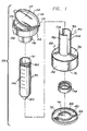
- Figure 1 is an exploded perspective view of a specimen collector in accordance with an embodiment of the invention;
- Figure 2 is a cross-sectional view of the collector illustrated in Figure 1;
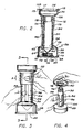
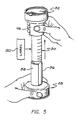
- Figure 3 is a side elevational view of the specimen collector shown fully assembled and illustrating a stage of use; and
- Figures 4 and 5 are perspective views of the specimen collector as shown in Figure 3 at various other stages of use.
- Figures 6 and 7, which are perspective views of presently available specimen collection apparatus, have been referred to above and will not be described again.
- The present invention is directed to a specimen collecting apparatus having a base stand in which a specimen vial is held in a substantially upright position. A funnel is fitted partly into the vial open end. The base stand, in conjunction with a portion of the funnel, substantially encloses the vial, isolating the vial from the specimen being collected. A vial cap is housed on a lid which is detachable to and upon which the base stand rests. This lid is formed to be grasped by the user and also to hold the cap while coupling the cap to and/or releasing the cap from the vial, without the user having to touch the cap. This minimizes the potential of spreading infection to the medical personnel who handle the apparatus and of contaminating the specimen by the handling of the cap.
- Referring now to FIGURES 1 and 2, the apparatus of the invention is seen generally at 26. The
apparatus 26 includes abase stand 28,specimen vial 30 andfunnel 32. Thevial 30 is a substantially elongated hollow tube having a closed lower end 60 and an oppositeopen end 61. A portion of thefunnel 32 can be inserted in the vialopen end 61. The upper surface of thevial 30, contiguous to theopen end 61, is formed with threads which are threadably mateable with a threadedvial cap 74. Preferably, a graduation scale (usually a 50 millimeter graduation scale) is provided along the length of thevial 30, as indicated generally at 100. - The base stand 28 is a substantially hollow tubular structure having a circular
peripheral wall 36 and anupper wall 38. Thisupper wall 38 is provided with areceptacle 34 in which thevial 30 can be held in a subtantially upright position. Alid 40 is detachably coupled to thelower end 39 of the base stand 28 which is opened. Thislid 40 is a substantially circular wall detachably coupled to the base stand 28 in any suitable manner. - In accordance with a preferred embodiment, this
lid 40 has acircular lip 66 which extends generally upward about thelid 40 periphery. When thebase stand 28 is placed on thelid 40 thislip 66 encicles the base standlower end 39. Thelip 66 is formed with an inwardly extendingannular rib 68 that is spaced away from the surface of thelid 40 to define anannular groove 72. Amating rib 70, which is formed to extend out from theperipheral wall 36 about thelower end 39 can be placed in thisgroove 72. A user of theapparatus 26 places the base stand 28 into thelid 40 so that theribs lid 40 is comprised of a resilient material to allow theribs base stand 28 is placed onto thelid 40. This is but one mechanism allowing thebase stand 28 andlid 40 to be repeatably coupled and decoupled. - The
lid 40 further includes a housing in which thevial cap 74 can be held, as indicated generally at 76. Thishousing 76 holds thecap 74 as it is coupled to and/or released from thevial 30 as thelid 40 is grasped by the patient or other personnel. Thehousing 76 is formed from a substantially ring-shapedenclosure 78 which extends generally upward from and is integral with thelid 40. Thecap 74 is placed into thisenclosure 78. In accordance with a preferred embodiment, theenclosure 78 is dimensioned to snugly fit thecap 74 and has aninner surface 79 which is formed to grip the outer peripheral surface of thecap 74, as thecap 74 is secured to and/or removed from thevial 30. Typically, these surfaces have cooperatively mating transverse ribs and grooves which interlock to allow theenclosure 78 to frictionally grip thecap 74 as the cap is threaded to or removed from thevial 30. - When the
lid 40 is coupled to thebase stand 28, thecap 74 and thehousing 76 are placed in thebase stand 28. This ensures that thecap 74 is isolated and free from contamination during the collecting of the specimen. - As better seen in FIGURE 2, the base stand 28
upper wall 38 defines thereceptacle 34 in which the lower closed end 60 of thevial 30 is placed. Thisreceptacle 34 is defined by aperipheral wall 42 which has a lower end from which ashoulder 64 extends radially inward for a specified distance, thus forming anaperture 62. The lower end 60 of thespecimen vial 30 can be placed in thisreceptacle 34 and partially pass through thisaperture 62. The remaining portion of thevial 30 lower end 60 rests upon theshoulder 64. Thereceptacle 34 is dimensioned to snugly retain thevial 30 in a substantially vertical or upright position. In accordance with another embodiment, not illustrated, thevial 30 is formed with a polygonal configured skirt extending down about the lower end 60. This allows thevial 30 to be free standing. This type of formedvial 30 would be receivable in the describedreceptacle 34. - Preferably, the base stand 28 further includes a substantially
tubular enclosure 94 which extends upward from thewall 38 about thereceptacle 34. Thisenclosure 94 partially surrounds and encloses a portion of thevial 30, as better seen in FIGURE 3. Thisenclosure 94 is formed by two opposing upwardly extending arcuately shapedwalls walls longitudinally cutaways cutaways enclosure 94. In accordance with this embodiment, thesewalls apparatus 10 to grasp aspecimen vial 30 which is positioned in theenclosure 94. Furthermore, the 50ml graduation scale 100, and the contents of thecollection tube 30, can be observed through either of thesecutaways enclosure 94 may be comprised of a transparent material. - A specimen, e.g. sputum, is delivered into the
specimen vial 30 via thefunnel 32. Thefunnel 32 is formed with atapered passageway 108 which longitudinally traverses thefunnel 32 from a first larger funnel opening 109 to a secondsmaller funnel opening 110. The lower portion of thefunnel 32 includes aneck portion 112. Thisneck portion 112 is dimensioned to be snugly fit in theopen end 61 of thevial 30. The second smaller funnel opening 110 is provided at the lower end of theneck portion 112. Adetachable cover 114 is provided to seal theopen end 109 of thefunnel 32. Thiscover 114 can be lifted off thefunnel 32 when it is desired to introduce a specimen through thepassageway 108 into thevial 30. Preferably thiscover 114 is attached to thefunnel 32 by ahinge 115. Thecover 114 is formed as a cup-shapedbody 117, which is dimensioned to be snugly fit in thepassageway 108 contiguous to theopen end 109. This cup-like body 117 has an outwardly extendingflange 119 which is nested down upon thefunnel 32 when thebody 117 is positioned in thepassageway 108. - The
funnel 32 also includes a substantiallytubular sleeve 116 which extends downwards, substantially coaxial with thepassageway 108, about theneck portion 112. This defines anannular area 118 between thetubular sleeve 116 andneck portion 112 in which the upper portion of thevial 30 can be placed. Preferably, thissleeve 116 extends sufficiently downward to enclose at least the upper part of thetubular enclosure 94. In this manner, thespecimen vial 30 is substantially enclosed by the combination of theenclosure 94 and thetubular sleeve 116. This provides a protective barrier about thevial 30 to minimize the accumulation on theexterior vial surface 30 of any specimen. This reduces the potential of transmitting infection to those who handle thevial 30. - Referring now to FIGURES 3, 4 and 5 simultaneously, the procedure for collecting specimen and for sealing the
vial 30 in accordance with an embodiment of the invention will now be described in detail. Typically, the fully assembledapparatus 26, with thefunnel 32 inserted in thevial 30, is provided in a sealed container, not shown. This sealed container minimizes contamination of theapparatus 26 in transit, and is typically a polyethylene bag or enclosure. - The patient or appropriate medical personnel dislodges the
vial 30, with thefunnel 32 in place, from thebase stand 28. This is accomplished, as illustrated in FIGURE 5, by grasping thefunnel 32 about thetubular sleeve 116 with one hand, holding the base stand 28 down with the other handle and lifting the combinedvial 30 and funnel 32 assembly out of thebase stand 28. The removal of the vial 309 and funnel 32 in the manner described is facilitated by providing that the fit of thefunnel 32 in thevial 30 is tighter than the fit of thevial 30 in thebase stand receptacle 34. That is, when the user pulls up on thefunnel 32, while holding down thebase 28, thevial 30 will more easily be dislodged from the base stand 28 than thefunnel 32. - Once the
vial 30 with thefunnel 32 have been removed from the base stand 28 an appropriate marking is provided on thevial 30 outer surface to indicate the identity of the patient. Typically, a self-adheringlabel 120, isprovided with the assembledapparatus 26 in the polyethylene bag or enclosure. The identity of the patient and other appropriate information, e.g., the type of testing which is desired to be performed on the specimen, is written on the label. Once the label is adhered to thevial 30 surface, thevial 30 and funnel 32 assembly is reinserted in thebase stand receptacle 34. Usually an appropriate medical personnel will carry out this step of the specimen-collecting operation. - The patient or appropriate medical personnel then lifts the
cover 114 off from thefunnel 32. A specified amount of specimen is delivered into thespecimen vial 30 through thepassageway 108 of thefunnel 32. After the specified amount of specimen has been delivered into thespecimen vial 30, as observed through either of thecutaways funnel 32. As shown in FIGURE 3, the user will grasp thevial 30, by compressing the twowalls vial 30 in thebase stand receptacle 34. As illustrated, thefunnel 32 is grasped about thetubular sleeve 116 to minimize any potential contact with any specimen which may be found on thefunnel 32 and/or to minimize any contamination. Thefunnel 32 is removed by twisting thefunnel 32 off while grasping thevial 30, again by compressing thewalls lid 40 is then removed from thebase stand 28 and used as a capping device for threadably secure thecap 74 to thespecimen vial 30. Thelid 40 is then pulled off thecap 74 and mounted back upon thebase stand 28, in the manner described above. Again, the patient or medical personnel will grip thevial 30 as thecap 74 is threaded to thevial 30 by compressing thewalls - While the preferred embodiments have been described and illustrated, various modifications and substitutions may be made thereto without departing from the scope of the invention. Accordingly, it is to be understood that the present invention has been described by way of illustration and not limitation.
Claims (14)
- A specimen collecting apparatus comprising:
a substantially elongated tubular container (30) having a first closed end (60) and a second open end (61);
collection means (32) which is removably secured to said container second open end (61) for directing said specimen into said container (30);
closing means (74) formed to releasably close said container open end (61) after removal of said collection means (32);
means (28) for supporting said container (30) with or without said collection means (32) in a substantially upright position; and
container gripping means (94) which extends up from said supporting means (28) about said container (30) formed to releasably grip said container (30);
characterised in that said container gripping means (94) partially surrounds said container (30) and includes two substantially arcuately shaped walls (96, 98) which extend upwards from said supporting means (28) to at least partially enclose said container (30), said upwardly extending walls (96, 98) being deflectable towards and back away from each other to allow said container (30) to be gripped, whereby said container (30) is held in said supporting means (28) when said collection means (32) is removed therefrom and/or when said closing means (74) is coupled and/or removed from said container (30). - The apparatus of claim 1, wherein said collection means is a funnel (32) having open upper and bottom ends with a passageway (108) therebetween, said funnel (32) having a substantially tubular neck portion (112) extending down from said bottom end which is snugly receivable in said container open end (61) sufficiently to allow said container (30) to be removed from said supporting means (28) by use of said funnel (32).
- The apparatus of claim 2, wherein said funnel (32) further includes a substantially tubular collar (116) extending downward and substantially coaxial with said neck portion (112), said collar (116) being spatially separated from said neck portion (112) to allow at least a portion of said container (30) to be placed therebetween.
- The apparatus of claim 3, wherein at least a portion of said upwardly extending walls (96, 98) is positionable between said tubular collar (116) and said funnel neck portion (112) with said container (30).
- The apparatus of claims 2, 3 or 4, wherein said funnel (32) further includes a cover (114) releasably coupled to said funnel (32) and fitted into said funnel (32) upper open end.
- The apparatus of any one of the preceding claims, wherein said supporting means (28) is a body defining a receptacle (34) in which said container (30) is received and supported in said upright position, said body (36/38) further defining a hollow (76) in which said closing means (74) is at least partially positioned when said graspable means (40) is coupled to said body (36/38), and wherein said collection means (32) is sufficiently secured to said container second open end (61) to allow said container (30) to be removed from said body receptacle (34) by use of said collection means (32).
- The apparatus of claim 6, wherein said graspable means is a substantially planar wall (40) releasably coupled to said body (36/38), said wall (40) including an enclosure (78) for housing and holding said closing means (74) as said closing means (74) is coupled to and/or released from said container (30), said wall enclosure (78) and said closing means (74) being positioned in said body hollow (76) when said wall (40) is coupled to said body (36/38).
- The apparatus of any one of the preceding claims, wherein said support means (28) comprises a substantially hollow tubular base portion defined by a substantially circular peripheral wall (36) having an upper end connected to a wall (38) in which a receptacle (34) for receiving and retaining said container (30) in said substantially upright position is formed and a lower open end.
- The apparatus of claim 8, wherein said graspable means is a substantially planar wall (40) which is detachably coupled to said base portion at said peripheral wall open end, said planar wall (40) including a means for housing and holding said closing means (74) as said closing means (74) is coupled and/or released from said container (30), said housing means (78) further positioning said closing means (74) in said base portion when said planar wall (40) is coupled to said base portion.
- The apparatus of claim 9, wherein said housing and holding means comprises a substantially circular enclosure (78) integrally formed in said planar wall (40) in which said closing means (74) can be place, said circular enclosure (78) including means for engaging said closing means positioned in said circular enclosure (78) as said closing means (74) is coupled and/or released from said container (30).
- The apparatus of claim 10, wherein said closing means is a substantially circular threaded cap (74).
- The apparatus of claim 11, wherein at least a portion of said planar wall (40) is substantially larger in width than said circular enclosure (78), whereby said larger wall portion is grasped as said closing means (74) is coupled and/or released from said container (30).
- The apparatus of claim 10, 11 or 12, wherein said planar wall (40) is substantially circular and has a diameter larger than said circular enclosure diameter.
- The apparatus of claim 10, 11, 12 or 13, wherein said engaging means comprises providing that said planar wall enclosure has an inner peripheral surface formed to engage the outer peripheral surface of said closing means (74) as said closing means (74) is coupled to and/or released from said container (30).
Priority Applications (1)
| Application Number | Priority Date | Filing Date | Title |
|---|---|---|---|
| AT87305204T ATE70178T1 (en) | 1986-06-16 | 1987-06-12 | SAMPLER. |
Applications Claiming Priority (2)
| Application Number | Priority Date | Filing Date | Title |
|---|---|---|---|
| US06/874,766 US4741346A (en) | 1986-06-16 | 1986-06-16 | Speciman collector |
| US874766 | 2001-06-05 |
Publications (3)
| Publication Number | Publication Date |
|---|---|
| EP0250170A2 EP0250170A2 (en) | 1987-12-23 |
| EP0250170A3 EP0250170A3 (en) | 1988-11-30 |
| EP0250170B1 true EP0250170B1 (en) | 1991-12-11 |
Family
ID=25364535
Family Applications (1)
| Application Number | Title | Priority Date | Filing Date |
|---|---|---|---|
| EP87305204A Expired - Lifetime EP0250170B1 (en) | 1986-06-16 | 1987-06-12 | Specimen collector |
Country Status (8)
| Country | Link |
|---|---|
| US (1) | US4741346A (en) |
| EP (1) | EP0250170B1 (en) |
| JP (1) | JP2525817B2 (en) |
| AT (1) | ATE70178T1 (en) |
| CA (1) | CA1270413A (en) |
| DE (1) | DE3775119D1 (en) |
| ES (1) | ES2028078T3 (en) |
| GR (1) | GR3003996T3 (en) |
Families Citing this family (35)
| Publication number | Priority date | Publication date | Assignee | Title |
|---|---|---|---|---|
| US5024238A (en) * | 1989-01-10 | 1991-06-18 | Cancer Diagnostics, Inc. | Blood withdrawing apparatus and antigen testing method |
| US5003988A (en) * | 1989-06-21 | 1991-04-02 | La Mina Ltd. | Modular multiple fluid sample preparation assembly |
| US4961432A (en) * | 1989-01-10 | 1990-10-09 | Cancer Diagnostics, Inc. | Modular fluid sample preparation assembly |
| US4920975A (en) * | 1989-02-21 | 1990-05-01 | Biomedical Polymers, Inc. | Biological fluid collection apparatus with the cap on the cover |
| US4932081A (en) * | 1989-08-11 | 1990-06-12 | Becton, Dickinson And Company | Sputum cup |
| US5283038A (en) * | 1990-12-18 | 1994-02-01 | Saliva Diagnostic Systems, Inc. | Fluid sampling and testing device |
| US5342328A (en) * | 1993-03-22 | 1994-08-30 | Grossman Michael D | Medical body fluid sampler device and method |
| USD425618S (en) * | 1999-08-06 | 2000-05-23 | Becton, Dickinson And Company | Specimen collection device |
| US7070053B1 (en) * | 2000-09-05 | 2006-07-04 | Cv Holdings Llc | System, method, and apparatuses for maintaining, tracking, transporting and identifying the integrity of a disposable specimen container with a re-usable transponder |
| US6467642B2 (en) | 2000-12-29 | 2002-10-22 | Patrick L. Mullens | Cryogenic shipping container |
| US6539726B2 (en) | 2001-05-08 | 2003-04-01 | R. Kevin Giesy | Vapor plug for cryogenic storage vessels |
| DE10145424B4 (en) * | 2001-09-14 | 2005-09-29 | Sarstedt Ag & Co. | Device for carrying out a test for detecting particles in urine |
| US7482116B2 (en) | 2002-06-07 | 2009-01-27 | Dna Genotek Inc. | Compositions and methods for obtaining nucleic acids from sputum |
| US20050059906A1 (en) * | 2003-09-12 | 2005-03-17 | Garry Tsaur | Specimen collector |
| US7282181B2 (en) | 2004-09-16 | 2007-10-16 | Varian Inc. | Fluid collection and testing device |
| US8221381B2 (en) * | 2005-12-09 | 2012-07-17 | Dna Genotek Inc. | Container system for releasably storing a substance |
| WO2007095231A2 (en) * | 2006-02-14 | 2007-08-23 | Gametogenics Corporation | Collection system for biological sample |
| AU2012201156B2 (en) * | 2007-03-29 | 2013-09-12 | St Reproductive Technologies, Llc | Transportation and/or storage device comprising a double-walled insulating bulb |
| FR2914408B1 (en) * | 2007-03-29 | 2009-08-21 | Eric Cognard | TRANSPORT AND / OR STORAGE DEVICE HAVING DOUBLE-WALL INSULATING BULB |
| US20090038416A1 (en) * | 2007-08-07 | 2009-02-12 | Aleta Behrman Bonner | System and method for biological sample collection and analyte detection |
| KR101629046B1 (en) * | 2008-08-21 | 2016-06-09 | 디엔에이 제노텍 인코퍼레이티드 | Sample receiving device |
| WO2010065549A1 (en) * | 2008-12-01 | 2010-06-10 | Paul Slowey | Multi compartment body part scraping fluid collection device |
| BR112012004688A2 (en) * | 2009-09-04 | 2019-09-24 | Atomo Diagnostics Pty Ltd | sampling device to collect a body fluid. |
| EP2537016B1 (en) | 2010-02-01 | 2016-04-20 | Oasis Diagnostics Corporation | Biological sample collection system |
| US9113850B2 (en) | 2010-08-20 | 2015-08-25 | Reflex Medical Corp. | Saliva collection device |
| EP3150702B1 (en) | 2011-06-19 | 2021-05-19 | DNA Genotek, Inc. | Devices, solutions and methods for sample collection |
| MX356101B (en) * | 2012-02-28 | 2018-05-14 | Rajendra Desai Akhil | Female urination receiver. |
| US9138747B2 (en) * | 2012-03-26 | 2015-09-22 | Alpha Tec Systems, Inc. | Specimen collection apparatus |
| US10302535B2 (en) * | 2013-09-12 | 2019-05-28 | CellectGen, Inc. | Biofluid collection and filtration device |
| US10799422B2 (en) * | 2017-05-30 | 2020-10-13 | Spectrum Solutions L.L.C. | Sample collection kit including removable stopper |
| CN113316646A (en) | 2018-11-20 | 2021-08-27 | 光谱解决方案有限责任公司 | Sample collection system including sealing cap and valve |
| US11882824B2 (en) * | 2019-03-08 | 2024-01-30 | Fisher Bioservices Inc. | Cryogenic vial sleeve and related systems and methods |
| US11701094B2 (en) | 2019-06-20 | 2023-07-18 | Spectrum Solutions L.L.C. | Sample collection system including valve and plug assemblies |
| USD1003451S1 (en) * | 2022-01-18 | 2023-10-31 | Hollister Incorporated | Fluid absorption test tube |
| WO2024044233A2 (en) * | 2022-08-25 | 2024-02-29 | Access Bio, Inc. | Diagnostic assay device having microreactor |
Family Cites Families (5)
| Publication number | Priority date | Publication date | Assignee | Title |
|---|---|---|---|---|
| US3235175A (en) * | 1963-04-15 | 1966-02-15 | Ames Lab Tek Inc | Method of collecting and condensing a medical specimen |
| US3518164A (en) * | 1967-04-11 | 1970-06-30 | B D Lab Inc | Diagnostic sputum collection system |
| US4283498A (en) * | 1979-10-29 | 1981-08-11 | Schlesinger Joseph D | Biological specimen collection and transport system |
| US4761379A (en) * | 1984-08-09 | 1988-08-02 | Becton, Dickinson And Company | Biological specimen collection device |
| US4589548A (en) * | 1984-12-06 | 1986-05-20 | Biomedical Polymers, Inc. | Sputum collection apparatus |
-
1986
- 1986-06-16 US US06/874,766 patent/US4741346A/en not_active Expired - Lifetime
-
1987
- 1987-06-05 CA CA000538925A patent/CA1270413A/en not_active Expired - Lifetime
- 1987-06-12 DE DE8787305204T patent/DE3775119D1/en not_active Expired - Fee Related
- 1987-06-12 EP EP87305204A patent/EP0250170B1/en not_active Expired - Lifetime
- 1987-06-12 ES ES198787305204T patent/ES2028078T3/en not_active Expired - Lifetime
- 1987-06-12 AT AT87305204T patent/ATE70178T1/en active
- 1987-06-15 JP JP62148893A patent/JP2525817B2/en not_active Expired - Lifetime
-
1992
- 1992-03-11 GR GR910402035T patent/GR3003996T3/el unknown
Also Published As
| Publication number | Publication date |
|---|---|
| JP2525817B2 (en) | 1996-08-21 |
| GR3003996T3 (en) | 1993-03-16 |
| ES2028078T3 (en) | 1992-07-01 |
| CA1270413A (en) | 1990-06-19 |
| DE3775119D1 (en) | 1992-01-23 |
| EP0250170A2 (en) | 1987-12-23 |
| EP0250170A3 (en) | 1988-11-30 |
| JPS6355461A (en) | 1988-03-09 |
| ATE70178T1 (en) | 1991-12-15 |
| US4741346A (en) | 1988-05-03 |
Similar Documents
| Publication | Publication Date | Title |
|---|---|---|
| EP0250170B1 (en) | Specimen collector | |
| US4761379A (en) | Biological specimen collection device | |
| US4589548A (en) | Sputum collection apparatus | |
| JP4132007B2 (en) | Cell separation device and metering syringe | |
| CA2397688C (en) | Liquid specimen collection system | |
| US7588562B2 (en) | Body fluid collection apparatus | |
| US2848999A (en) | Sampling apparatus | |
| EP1295561A1 (en) | Liquid specimen collection container. | |
| US4920975A (en) | Biological fluid collection apparatus with the cap on the cover | |
| EP0192453A2 (en) | Needle guard | |
| CA2023066C (en) | Sputum cup | |
| RU2394741C2 (en) | Garbage recipients built in walls for hospital and lab premises | |
| US4750636A (en) | Test tube opening hood and process | |
| AU8301298A (en) | Collection container assembly | |
| US3235175A (en) | Method of collecting and condensing a medical specimen | |
| US20230255604A1 (en) | Fluid Sample Collection Container With Cap and Removal Tool for Finger Grip Luer Adapter | |
| US11090647B2 (en) | Double bottom test tube kit and method therefore | |
| WO1999052442A1 (en) | Holding member for a urine sampling container | |
| US20230240669A1 (en) | Fluid Sample Collection Container With Removable Tube Holder |
Legal Events
| Date | Code | Title | Description |
|---|---|---|---|
| PUAI | Public reference made under article 153(3) epc to a published international application that has entered the european phase |
Free format text: ORIGINAL CODE: 0009012 |
|
| AK | Designated contracting states |
Kind code of ref document: A2 Designated state(s): AT BE CH DE ES FR GB GR IT LI LU NL SE |
|
| PUAL | Search report despatched |
Free format text: ORIGINAL CODE: 0009013 |
|
| AK | Designated contracting states |
Kind code of ref document: A3 Designated state(s): AT BE CH DE ES FR GB GR IT LI LU NL SE |
|
| 17P | Request for examination filed |
Effective date: 19890518 |
|
| 17Q | First examination report despatched |
Effective date: 19901030 |
|
| GRAA | (expected) grant |
Free format text: ORIGINAL CODE: 0009210 |
|
| AK | Designated contracting states |
Kind code of ref document: B1 Designated state(s): AT BE CH DE ES FR GB GR IT LI LU NL SE |
|
| PG25 | Lapsed in a contracting state [announced via postgrant information from national office to epo] |
Ref country code: FR Effective date: 19911211 |
|
| REF | Corresponds to: |
Ref document number: 70178 Country of ref document: AT Date of ref document: 19911215 Kind code of ref document: T |
|
| REF | Corresponds to: |
Ref document number: 3775119 Country of ref document: DE Date of ref document: 19920123 |
|
| ITF | It: translation for a ep patent filed |
Owner name: MODIANO & ASSOCIATI S.R.L. |
|
| PGFP | Annual fee paid to national office [announced via postgrant information from national office to epo] |
Ref country code: AT Payment date: 19920403 Year of fee payment: 6 |
|
| EN | Fr: translation not filed | ||
| REG | Reference to a national code |
Ref country code: ES Ref legal event code: FG2A Ref document number: 2028078 Country of ref document: ES Kind code of ref document: T3 |
|
| PLBE | No opposition filed within time limit |
Free format text: ORIGINAL CODE: 0009261 |
|
| STAA | Information on the status of an ep patent application or granted ep patent |
Free format text: STATUS: NO OPPOSITION FILED WITHIN TIME LIMIT |
|
| REG | Reference to a national code |
Ref country code: GR Ref legal event code: FG4A Free format text: 3003996 |
|
| 26N | No opposition filed | ||
| PG25 | Lapsed in a contracting state [announced via postgrant information from national office to epo] |
Ref country code: AT Effective date: 19930612 |
|
| EPTA | Lu: last paid annual fee | ||
| EAL | Se: european patent in force in sweden |
Ref document number: 87305204.7 |
|
| PGFP | Annual fee paid to national office [announced via postgrant information from national office to epo] |
Ref country code: NL Payment date: 19960328 Year of fee payment: 10 |
|
| PGFP | Annual fee paid to national office [announced via postgrant information from national office to epo] |
Ref country code: LU Payment date: 19960401 Year of fee payment: 10 |
|
| PGFP | Annual fee paid to national office [announced via postgrant information from national office to epo] |
Ref country code: GR Payment date: 19960429 Year of fee payment: 10 |
|
| PGFP | Annual fee paid to national office [announced via postgrant information from national office to epo] |
Ref country code: GB Payment date: 19960509 Year of fee payment: 10 |
|
| PGFP | Annual fee paid to national office [announced via postgrant information from national office to epo] |
Ref country code: SE Payment date: 19960517 Year of fee payment: 10 |
|
| PGFP | Annual fee paid to national office [announced via postgrant information from national office to epo] |
Ref country code: ES Payment date: 19960614 Year of fee payment: 10 |
|
| PGFP | Annual fee paid to national office [announced via postgrant information from national office to epo] |
Ref country code: DE Payment date: 19960625 Year of fee payment: 10 |
|
| PGFP | Annual fee paid to national office [announced via postgrant information from national office to epo] |
Ref country code: CH Payment date: 19960703 Year of fee payment: 10 Ref country code: BE Payment date: 19960703 Year of fee payment: 10 |
|
| PG25 | Lapsed in a contracting state [announced via postgrant information from national office to epo] |
Ref country code: LU Free format text: LAPSE BECAUSE OF NON-PAYMENT OF DUE FEES Effective date: 19970612 Ref country code: GB Free format text: LAPSE BECAUSE OF NON-PAYMENT OF DUE FEES Effective date: 19970612 |
|
| PG25 | Lapsed in a contracting state [announced via postgrant information from national office to epo] |
Ref country code: SE Effective date: 19970613 Ref country code: ES Free format text: LAPSE BECAUSE OF EXPIRATION OF PROTECTION Effective date: 19970613 |
|
| PG25 | Lapsed in a contracting state [announced via postgrant information from national office to epo] |
Ref country code: LI Free format text: LAPSE BECAUSE OF NON-PAYMENT OF DUE FEES Effective date: 19970630 Ref country code: GR Free format text: LAPSE BECAUSE OF NON-PAYMENT OF DUE FEES Effective date: 19970630 Ref country code: CH Free format text: LAPSE BECAUSE OF NON-PAYMENT OF DUE FEES Effective date: 19970630 Ref country code: BE Effective date: 19970630 |
|
| BERE | Be: lapsed |
Owner name: EVERGREEN INDUSTRIES INC. Effective date: 19970630 |
|
| PG25 | Lapsed in a contracting state [announced via postgrant information from national office to epo] |
Ref country code: NL Effective date: 19980101 |
|
| GBPC | Gb: european patent ceased through non-payment of renewal fee |
Effective date: 19970612 |
|
| REG | Reference to a national code |
Ref country code: CH Ref legal event code: PL |
|
| EUG | Se: european patent has lapsed |
Ref document number: 87305204.7 |
|
| NLV4 | Nl: lapsed or anulled due to non-payment of the annual fee |
Effective date: 19980101 |
|
| PG25 | Lapsed in a contracting state [announced via postgrant information from national office to epo] |
Ref country code: DE Free format text: LAPSE BECAUSE OF NON-PAYMENT OF DUE FEES Effective date: 19980303 |
|
| REG | Reference to a national code |
Ref country code: ES Ref legal event code: FD2A Effective date: 20000301 |
|
| PG25 | Lapsed in a contracting state [announced via postgrant information from national office to epo] |
Ref country code: IT Free format text: LAPSE BECAUSE OF NON-PAYMENT OF DUE FEES Effective date: 20050612 |