EP0251546A2 - Making automobile body panels having applied painted carrier films - Google Patents
Making automobile body panels having applied painted carrier films Download PDFInfo
- Publication number
- EP0251546A2 EP0251546A2 EP87305306A EP87305306A EP0251546A2 EP 0251546 A2 EP0251546 A2 EP 0251546A2 EP 87305306 A EP87305306 A EP 87305306A EP 87305306 A EP87305306 A EP 87305306A EP 0251546 A2 EP0251546 A2 EP 0251546A2
- Authority
- EP
- European Patent Office
- Prior art keywords
- substrate
- layer
- sheet layer
- sheet
- paint
- Prior art date
- Legal status (The legal status is an assumption and is not a legal conclusion. Google has not performed a legal analysis and makes no representation as to the accuracy of the status listed.)
- Granted
Links
Images

Classifications
-
- B—PERFORMING OPERATIONS; TRANSPORTING
- B29—WORKING OF PLASTICS; WORKING OF SUBSTANCES IN A PLASTIC STATE IN GENERAL
- B29C—SHAPING OR JOINING OF PLASTICS; SHAPING OF MATERIAL IN A PLASTIC STATE, NOT OTHERWISE PROVIDED FOR; AFTER-TREATMENT OF THE SHAPED PRODUCTS, e.g. REPAIRING
- B29C51/00—Shaping by thermoforming, i.e. shaping sheets or sheet like preforms after heating, e.g. shaping sheets in matched moulds or by deep-drawing; Apparatus therefor
- B29C51/16—Lining or labelling
-
- B—PERFORMING OPERATIONS; TRANSPORTING
- B29—WORKING OF PLASTICS; WORKING OF SUBSTANCES IN A PLASTIC STATE IN GENERAL
- B29C—SHAPING OR JOINING OF PLASTICS; SHAPING OF MATERIAL IN A PLASTIC STATE, NOT OTHERWISE PROVIDED FOR; AFTER-TREATMENT OF THE SHAPED PRODUCTS, e.g. REPAIRING
- B29C37/00—Component parts, details, accessories or auxiliary operations, not covered by group B29C33/00 or B29C35/00
- B29C37/0025—Applying surface layers, e.g. coatings, decorative layers, printed layers, to articles during shaping, e.g. in-mould printing
- B29C37/0028—In-mould coating, e.g. by introducing the coating material into the mould after forming the article
- B29C2037/0042—In-mould coating, e.g. by introducing the coating material into the mould after forming the article the coating being applied in solid sheet form, e.g. as meltable sheet
-
- B—PERFORMING OPERATIONS; TRANSPORTING
- B29—WORKING OF PLASTICS; WORKING OF SUBSTANCES IN A PLASTIC STATE IN GENERAL
- B29C—SHAPING OR JOINING OF PLASTICS; SHAPING OF MATERIAL IN A PLASTIC STATE, NOT OTHERWISE PROVIDED FOR; AFTER-TREATMENT OF THE SHAPED PRODUCTS, e.g. REPAIRING
- B29C43/00—Compression moulding, i.e. applying external pressure to flow the moulding material; Apparatus therefor
- B29C43/02—Compression moulding, i.e. applying external pressure to flow the moulding material; Apparatus therefor of articles of definite length, i.e. discrete articles
- B29C43/18—Compression moulding, i.e. applying external pressure to flow the moulding material; Apparatus therefor of articles of definite length, i.e. discrete articles incorporating preformed parts or layers, e.g. compression moulding around inserts or for coating articles
- B29C2043/185—Compression moulding, i.e. applying external pressure to flow the moulding material; Apparatus therefor of articles of definite length, i.e. discrete articles incorporating preformed parts or layers, e.g. compression moulding around inserts or for coating articles using adhesives
- B29C2043/186—Compression moulding, i.e. applying external pressure to flow the moulding material; Apparatus therefor of articles of definite length, i.e. discrete articles incorporating preformed parts or layers, e.g. compression moulding around inserts or for coating articles using adhesives hot-melt or heat activated adhesives
-
- B—PERFORMING OPERATIONS; TRANSPORTING
- B29—WORKING OF PLASTICS; WORKING OF SUBSTANCES IN A PLASTIC STATE IN GENERAL
- B29C—SHAPING OR JOINING OF PLASTICS; SHAPING OF MATERIAL IN A PLASTIC STATE, NOT OTHERWISE PROVIDED FOR; AFTER-TREATMENT OF THE SHAPED PRODUCTS, e.g. REPAIRING
- B29C2791/00—Shaping characteristics in general
- B29C2791/001—Shaping in several steps
-
- B—PERFORMING OPERATIONS; TRANSPORTING
- B29—WORKING OF PLASTICS; WORKING OF SUBSTANCES IN A PLASTIC STATE IN GENERAL
- B29C—SHAPING OR JOINING OF PLASTICS; SHAPING OF MATERIAL IN A PLASTIC STATE, NOT OTHERWISE PROVIDED FOR; AFTER-TREATMENT OF THE SHAPED PRODUCTS, e.g. REPAIRING
- B29C43/00—Compression moulding, i.e. applying external pressure to flow the moulding material; Apparatus therefor
- B29C43/02—Compression moulding, i.e. applying external pressure to flow the moulding material; Apparatus therefor of articles of definite length, i.e. discrete articles
- B29C43/18—Compression moulding, i.e. applying external pressure to flow the moulding material; Apparatus therefor of articles of definite length, i.e. discrete articles incorporating preformed parts or layers, e.g. compression moulding around inserts or for coating articles
- B29C43/183—Compression moulding, i.e. applying external pressure to flow the moulding material; Apparatus therefor of articles of definite length, i.e. discrete articles incorporating preformed parts or layers, e.g. compression moulding around inserts or for coating articles the preformed layer being a lining, e.g. shaped in the mould before compression moulding, or a preformed shell adapted to the shape of the mould
-
- B—PERFORMING OPERATIONS; TRANSPORTING
- B29—WORKING OF PLASTICS; WORKING OF SUBSTANCES IN A PLASTIC STATE IN GENERAL
- B29L—INDEXING SCHEME ASSOCIATED WITH SUBCLASS B29C, RELATING TO PARTICULAR ARTICLES
- B29L2031/00—Other particular articles
- B29L2031/30—Vehicles, e.g. ships or aircraft, or body parts thereof
- B29L2031/3005—Body finishings
Definitions
- This invention relates to a method of making automobile body panels.
- Automobile body panels are traditionally made of sheet metal or plastics material painted with layers of pigmented paints.
- the painting procedure for these panels requires elaborate facilities, and consequently involves heavy expense. For instance, a large area of floor space must be maintained in a clean-room environment for the spraying of paint and clear coat, and for the baking and curing of such paint and clear coat on the body panels.
- solvent-based paints have come to be considered undesirable in recent years because of environmental concerns. As a consequence, the evaporation of such solvents must be strictly controlled.
- the present invention is concerned with a method of making automobile body panels which permits elimination of the entire painting procedure in an automobile assembly plant.
- a method in accordance with the present invention comprises the combination of features specified in claim l.
- the method in accordance with the present invention thus involves the production of pre-painted carrier films which are then applied to automobile body panels.
- the method of applying the pre-painted carrier film to an automobile body panel can be automated for a production process.
- pre-painted carrier films can be applied to vehicle body panels such that all the body panels mounted on an automobile or other vehicle are colour-matched within an acceptable tolerance. This offers the possibility of improving the paint colour match on a vehicle.
- a method of applying pre-painted carrier films to automobile body panels such that all the body panels have the same colour appearance can be carried out by the following operative steps. Firstly, a layer of a pigmented paint is applied to a plastics film having sufficient thickness and rigidity. A layer of clear coat may optionally be applied on top of the paint layer to further improve the appearance. The uncoated side of this plastics film is then coated with a layer of an adhesive that can be heat-activated. This pre-painted carrier film is then heated in an oven to a temperature at which the plastics film became sufficiently pliable for it to be vacuum-formed. The temperature must also be sufficiently high to activate the adhesive layer on the back of the pre-painted film.
- the resulting heated pre-painted film is then positioned over a substrate for a body panel in a vacuum-forming device. Air is withdrawn from under the pre-painted film such that the film thereby wraps around and adheres to the substrate without forming defects such as air bubbles.
- vacuum holes are drilled into a supporting buck for the substrate in such a way that a heated film edge-wraps the substrate so that the edges of the substrate are covered by pre-painted film. After the excess film has been trimmed away from the substrate along the edges of the part, a completed automobile body panel with a painted surface is thereby ready for assembly to an automobile.
- US-A-4 496 628 discloses a laminate for the protection of motor vehicle bodies, for example rocker panels and adjacent parts, from abrasion damage
- US-A-3 55l 232 discloses a method of vacuum-forming laminated articles, for example decorative layers which are to be adhesively bonded to a substrate to provide structures such as interior automobile panels and glove compartment doors.
- the vacuum-former l0 comprises a vacuum box l2, a stretcher frame l4, a vacuum port l6 and a support buck l8.
- a pre-painted carrier film 20 is first loaded into the stretcher frame l4 with the paint side up, and a substrate 22 which is to be covered by the pre-painted carrier film 20 is loaded on to the support buck l8.
- the support buck l8 is mounted on a vacuum plate 24 for the evacuation of air trapped under the pre-painted carrier film 20.
- the substrate 22 may be constructed of any suitable material, such as a reaction precursor of urethane, a reaction precursor of polyamide (nylon), a glass fibre-reinforced sheet moulding compound, an injection-mouldable thermoplastic material or a metallic material.
- carrier films which have proved suitable are an extruded polyurethane film supplied by Dow Chemical Company, and a thermoplastic polyester film supplied by Eastman Chemical Products.
- the thickness of the film is approximately 0.25 mm (0.0l0 inch).
- the rear surface of the film was coated with a commercial acrylic contact adhesive capable of being activated at a temperature of l38°C (280°F).
- the carrier films were coated by means of a spray painting technique with a red maple metallic paint supplied by PPG Industries under the trade mark Durethane l0l.
- the size of the film samples used was approximately 60 cm ⁇ 60 cm.
- the carrier films were hand-sprayed to an average coating thickness of between 0.025 and 0.l0 mm (0.00l and 0.004 inch).
- the cure conditions used for these pre-painted carrier films were a temperature of ll0°C and a time of 30 minutes.
- the pre-painted carrier film 20 is clamped into the stretcher frame l4, which can be moved horizontally into an oven (not shown) for heating.
- An oven equipped with quartz heaters can for example be used for rapid heating of the film to a temperature of approximately l49°C (300°F).
- An optical thermometer is conveniently used to monitor the surface temperature of the film in the oven. Once the surface temperature reaches the desirable forming temperature, the stretcher frame l4 is rapidly moved out of the oven and positioned over the top of the vacuum box l2.
- Figure 2 shows a heated pre-painted carrier film 20 sagging from its clamped position into the vacuum box l2. Vacuum is then applied immediately to the bottom of the vacuum box l2 by way of the vacuum port l6, to evacuate air trapped under the carrier film 20.
- Figure 3 shows that as air is evacuated from the vacuum box l2, the pre-painted carrier film 20 is drawn down further on to the substrate 22 to cover the entire surface.
- the carrier film 20 sticks to the substrate on contact by the acrylic adhesive backing.
- Figure 4 shows the final stage of the vacuum-forming process, wherein more air is evacuated from the vacuum box l2.
- the film 20 is thereby drawn down evenly over the edges of the support box l8.
- the substrate 22 with the pre-painted carrier film 20 adhered to it can then be removed from the vacuum box l2, for excess film to be trimmed off along the edges of the substrate.
- a movable support buck and a movable inner vacuum box are used instead of the stationary support buck used in the previous embodiment.
- This is shown in Figure 5, according to which a movable support buck 40 and a movable inner box 42 are mounted inside an outer vacuum box 44. Both the support buck 40 and the inner box 42 are mounted on air cylinders which permit movement up and down as desired.
- Figure 5 also shows a pre-painted carrier film 46 mounted in a stretcher frame 48 which can be moved rapidly into and out of a heater 50.
- a substrate 52 for a body panel is placed on the support buck 40 with the support buck 40 in its 'up' position.
- the pre-painted carrier film 46 is prepared essentially as in the previous embodiment.
- the carrier film 46 is placed under the heater 50 until the surface temperature of the film reaches a temperature of l49°C (300°F) and the film starts sagging.
- the film is then rapidly moved out of the heater 50 and positioned over the vacuum box 44.
- the support buck 40 is rapidly raised, such that the carrier film 46 touches the highest point of the substrate 52.
- Air is withdrawn through the vacuum port 56 to evacuate air trapped under the carrier film 46.
- the air is evacuated around the edges of the substrate 52 by way of vacuum holes 58 drilled in the top edge of the support buck 40.
- Figure 7 shows a condition in which the pre-painted carrier film 46 continues to be drawn down on to the substrate 52, and adheres to it on contact with no air entrapment. As the carrier film 46 reaches the edges of the substrate 52 and continues to be drawn down on to the sides of the support buck 40, a stretched film section is created between the edges of the substrate and the sides of the support buck 40.
- the support buck 40 in the final step of the stretch-forming process the support buck 40, with the substrate 52 in position on it, is lowered through a distance of approximately 25mm (one inch), to cause the stretched carrier film 46 to droop at 60.
- the stretched carrier film 46 is drawn under the substrate 52 at 62, where it adheres on contact to the rear edges 64 of the substrate 52.
- This last step of the stretch-forming process wherein the support buck 40 and the substrate 52 are both lowered, accomplishes an important task of edge-wrapping the carrier film to the rear surface of the substrate.
- This procedure when carried out in an automated manner, represents a great saving in the manual labour otherwise required to edge-wrap each substrate.
- the substrate with the pre-painted carrier film adhered to it may then be removed for a trimming operation.
- an aromatic sulphonic acid catalyst solution such as that supplied by PPG under the designation PPG 900-l6l6. This allows the clear-coat layer to cure under the same conditions as the Durethane l0l topcoats. In some cases a clear coat may be applied to the top of a carrier film after vacuum-forming, for even better results.
- the gloss level (at a temperature of -6.7°C/20°F) of the final product was increased from a value of l5 when no clear coat was used to a value of 65 when a clear coat was used.
- the level of haze (at a temperature of -l6.7°C/2°F) was drastically reduced from a value of 60 to a value of less than 5 in the same samples.
- the gloss readings were obtained on a Hunter 20° portable gloss meter.
- the haze values were obtained by the use of a Hunter Dori-gon model D47-6 abridged goniophotometer.
- a thin layer of clear coat may be applied to the pre-painted carrier film either before or after the vacuum-forming process.
- a clear coat it will generally be more desirable to apply a clear coat on top of a pre-painted carrier film before the stretch-forming process.
- the present invention completely avoids the need for the usual paint facilities in an automobile assembly plant, since the pre-painted carrier films may be vacuum-formed directly on to vehicle body panels in a simple and automated procedure.
Abstract
Description
- This invention relates to a method of making automobile body panels.
- Automobile body panels are traditionally made of sheet metal or plastics material painted with layers of pigmented paints. The painting procedure for these panels requires elaborate facilities, and consequently involves heavy expense. For instance, a large area of floor space must be maintained in a clean-room environment for the spraying of paint and clear coat, and for the baking and curing of such paint and clear coat on the body panels. Moreover, solvent-based paints have come to be considered undesirable in recent years because of environmental concerns. As a consequence, the evaporation of such solvents must be strictly controlled.
- The present invention is concerned with a method of making automobile body panels which permits elimination of the entire painting procedure in an automobile assembly plant.
- To this end a method in accordance with the present invention comprises the combination of features specified in claim l.
- The method in accordance with the present invention thus involves the production of pre-painted carrier films which are then applied to automobile body panels. The method of applying the pre-painted carrier film to an automobile body panel can be automated for a production process.
- By the use of the present invention, pre-painted carrier films can be applied to vehicle body panels such that all the body panels mounted on an automobile or other vehicle are colour-matched within an acceptable tolerance. This offers the possibility of improving the paint colour match on a vehicle.
- In a preferred embodiment of a method in accordance with the present invention, a method of applying pre-painted carrier films to automobile body panels such that all the body panels have the same colour appearance can be carried out by the following operative steps. Firstly, a layer of a pigmented paint is applied to a plastics film having sufficient thickness and rigidity. A layer of clear coat may optionally be applied on top of the paint layer to further improve the appearance. The uncoated side of this plastics film is then coated with a layer of an adhesive that can be heat-activated. This pre-painted carrier film is then heated in an oven to a temperature at which the plastics film became sufficiently pliable for it to be vacuum-formed. The temperature must also be sufficiently high to activate the adhesive layer on the back of the pre-painted film. The resulting heated pre-painted film is then positioned over a substrate for a body panel in a vacuum-forming device. Air is withdrawn from under the pre-painted film such that the film thereby wraps around and adheres to the substrate without forming defects such as air bubbles.
- In an alternative embodiment vacuum holes are drilled into a supporting buck for the substrate in such a way that a heated film edge-wraps the substrate so that the edges of the substrate are covered by pre-painted film. After the excess film has been trimmed away from the substrate along the edges of the part, a completed automobile body panel with a painted surface is thereby ready for assembly to an automobile.
- Amongst the prior art, US-A-4 496 628 discloses a laminate for the protection of motor vehicle bodies, for example rocker panels and adjacent parts, from abrasion damage, and US-A-3 55l 232 discloses a method of vacuum-forming laminated articles, for example decorative layers which are to be adhesively bonded to a substrate to provide structures such as interior automobile panels and glove compartment doors.
- In the drawings:
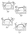
- Figure l is a schematic view of a vacuum-forming arrangement wherein a pre-painted carrier film is stretched over a substrate to be covered;
- Figure 2 is a schematic view similar to Figure l but showing the effect of applying vacuum from the bottom of a forming box to draw the pre-painted carrier film down on to the substrate;
- Figure 3 is a schematic view similar to Figure l but showing the pre-painted carrier film completely covering the substrate under the effect of the vacuum;
- Figure 4 is a schematic view similar to Figure l but showing the pre-painted carrier film drawn down evenly over the edges of the substrate;
- Figure 5 is a schematic view showing an alternative embodiment in which a support buck, an inner box and an outer vacuum box are used;
- Figure 6 is a schematic view similar to Figure 5 but showing the effect of applying vacuum under the support buck after the inner box has been raised;
- Figure 7 is a schematic view similar to Figure 5 but showing a pre-painted carrier film stretched down to cover the substrate and the sides of the inner box; and
- Figure 8 is a schematic view similar to Figure 5 but showing the support buck in a lowered position for edge-to-edge wrapping of the substrate.
- With reference now initially to Figure l of the drawings, wherein a vacuum-former l0 is schematically shown, the vacuum-former l0 comprises a vacuum box l2, a stretcher frame l4, a vacuum port l6 and a support buck l8. A
pre-painted carrier film 20 is first loaded into the stretcher frame l4 with the paint side up, and asubstrate 22 which is to be covered by thepre-painted carrier film 20 is loaded on to the support buck l8. The support buck l8 is mounted on avacuum plate 24 for the evacuation of air trapped under the pre-paintedcarrier film 20. - The
substrate 22 may be constructed of any suitable material, such as a reaction precursor of urethane, a reaction precursor of polyamide (nylon), a glass fibre-reinforced sheet moulding compound, an injection-mouldable thermoplastic material or a metallic material. - Examples of carrier films which have proved suitable are an extruded polyurethane film supplied by Dow Chemical Company, and a thermoplastic polyester film supplied by Eastman Chemical Products. The thickness of the film is approximately 0.25 mm (0.0l0 inch). The rear surface of the film was coated with a commercial acrylic contact adhesive capable of being activated at a temperature of l38°C (280°F). The carrier films were coated by means of a spray painting technique with a red maple metallic paint supplied by PPG Industries under the trade mark Durethane l0l. The size of the film samples used was approximately 60 cm × 60 cm. The carrier films were hand-sprayed to an average coating thickness of between 0.025 and 0.l0 mm (0.00l and 0.004 inch). The cure conditions used for these pre-painted carrier films were a temperature of ll0°C and a time of 30 minutes.
- As is shown in Figure l, the
pre-painted carrier film 20 is clamped into the stretcher frame l4, which can be moved horizontally into an oven (not shown) for heating. An oven equipped with quartz heaters can for example be used for rapid heating of the film to a temperature of approximately l49°C (300°F). An optical thermometer is conveniently used to monitor the surface temperature of the film in the oven. Once the surface temperature reaches the desirable forming temperature, the stretcher frame l4 is rapidly moved out of the oven and positioned over the top of the vacuum box l2. - Figure 2 shows a heated pre-painted
carrier film 20 sagging from its clamped position into the vacuum box l2. Vacuum is then applied immediately to the bottom of the vacuum box l2 by way of the vacuum port l6, to evacuate air trapped under thecarrier film 20. - Figure 3 shows that as air is evacuated from the vacuum box l2, the
pre-painted carrier film 20 is drawn down further on to thesubstrate 22 to cover the entire surface. Thecarrier film 20 sticks to the substrate on contact by the acrylic adhesive backing. - Figure 4 shows the final stage of the vacuum-forming process, wherein more air is evacuated from the vacuum box l2. The
film 20 is thereby drawn down evenly over the edges of the support box l8. Thesubstrate 22 with thepre-painted carrier film 20 adhered to it can then be removed from the vacuum box l2, for excess film to be trimmed off along the edges of the substrate. - In the alternative embodiment which is shown in Figures 5 to 8, a movable support buck and a movable inner vacuum box are used instead of the stationary support buck used in the previous embodiment. This is shown in Figure 5, according to which a
movable support buck 40 and a movableinner box 42 are mounted inside anouter vacuum box 44. Both thesupport buck 40 and theinner box 42 are mounted on air cylinders which permit movement up and down as desired. Figure 5 also shows apre-painted carrier film 46 mounted in astretcher frame 48 which can be moved rapidly into and out of aheater 50. With reference to Figure 5, at the start of a forming cycle asubstrate 52 for a body panel is placed on thesupport buck 40 with thesupport buck 40 in its 'up' position. Thepre-painted carrier film 46 is prepared essentially as in the previous embodiment. Thecarrier film 46 is placed under theheater 50 until the surface temperature of the film reaches a temperature of l49°C (300°F) and the film starts sagging. The film is then rapidly moved out of theheater 50 and positioned over thevacuum box 44. Thesupport buck 40 is rapidly raised, such that thecarrier film 46 touches the highest point of thesubstrate 52. Air is withdrawn through thevacuum port 56 to evacuate air trapped under thecarrier film 46. The air is evacuated around the edges of thesubstrate 52 by way ofvacuum holes 58 drilled in the top edge of thesupport buck 40. - Figure 7 shows a condition in which the
pre-painted carrier film 46 continues to be drawn down on to thesubstrate 52, and adheres to it on contact with no air entrapment. As thecarrier film 46 reaches the edges of thesubstrate 52 and continues to be drawn down on to the sides of thesupport buck 40, a stretched film section is created between the edges of the substrate and the sides of thesupport buck 40. - As is shown in Figure 8, in the final step of the stretch-forming process the
support buck 40, with thesubstrate 52 in position on it, is lowered through a distance of approximately 25mm (one inch), to cause the stretchedcarrier film 46 to droop at 60. As air is meanwhile being continuously withdrawn from the cavity between thesupport buck 40 and theinner box 42, the stretchedcarrier film 46 is drawn under thesubstrate 52 at 62, where it adheres on contact to therear edges 64 of thesubstrate 52. This last step of the stretch-forming process, wherein thesupport buck 40 and thesubstrate 52 are both lowered, accomplishes an important task of edge-wrapping the carrier film to the rear surface of the substrate. This procedure, when carried out in an automated manner, represents a great saving in the manual labour otherwise required to edge-wrap each substrate. The substrate with the pre-painted carrier film adhered to it may then be removed for a trimming operation. - During the stretch-forming process, a deformation of between 30% to l50% has been noted in the stretched carrier film when the film sags after heating and is then drawn by the vacuum action on to the substrate. The contour of the substrate and its orientation largely determine the localised deformation of the carrier film.
- The addition of a clear coat layer to the pre-painted carrier film before the vacuum-forming process has been found to produce a great improvement in the colour appearance of the vacuum-formed carrier film on a substrate. For this purpose it is possible to use a flexible clear coat supplied by PPG Industries under the designation URC-l000 at a thickness of 0.025 mm (0.00l inch).
- To achieve proper curing of a coating containing a clear-coat top layer, it is necessary to add 5% by weight of an aromatic sulphonic acid catalyst solution such as that supplied by PPG under the designation PPG 900-l6l6. This allows the clear-coat layer to cure under the same conditions as the Durethane l0l topcoats. In some cases a clear coat may be applied to the top of a carrier film after vacuum-forming, for even better results.
- In one test, in which a clear coat was applied on top of a pre-painted carrier film before vacuum-forming, the gloss level (at a temperature of -6.7°C/20°F) of the final product was increased from a value of l5 when no clear coat was used to a value of 65 when a clear coat was used. The level of haze (at a temperature of -l6.7°C/2°F) was drastically reduced from a value of 60 to a value of less than 5 in the same samples. The gloss readings were obtained on a
Hunter 20° portable gloss meter. The haze values were obtained by the use of a Hunter Dori-gon model D47-6 abridged goniophotometer. - It will be evident from the foregoing that when an improvement in the gloss level of a finished product is desired, a thin layer of clear coat may be applied to the pre-painted carrier film either before or after the vacuum-forming process. In a volume production system such as is used in the automotive industry, it will generally be more desirable to apply a clear coat on top of a pre-painted carrier film before the stretch-forming process.
- It is possible for large rolls of carrier film to be coated with a pigmented paint layer and a clear-coat layer and baked through a baking cycle to cure both the paint layer and the clear coat-layer. The resulting roll of coated film may then be stored for future use when such colour is required on a vehicle body panel.
- The present invention completely avoids the need for the usual paint facilities in an automobile assembly plant, since the pre-painted carrier films may be vacuum-formed directly on to vehicle body panels in a simple and automated procedure.
- In the preferred embodiment, this results from the described procedure involving pre-painting the
external sheet layer 20 with a durable paint on the top layer, and, after the bottom surface has been coated with an adhesive layer, thermo-forming the external sheet layer under vacuum on to therigid substrate layer 22.
Claims (8)
a substrate (22) having front and back surfaces, with the front surface of the substrate (22) being contoured to define a portion of the exterior surface of an automobile, and the substrate (22) being formed from a reaction precursor of urethane, a reaction precursor of polyamide (nylon), a glass fibre-reinforced sheet moulding compound, an injection-mouldable thermoplastic material or a metallic material;
a facing sheet layer (20) disposed over the entire front surface of the substrate (22) and contoured in detail in conformance with the contour of the front surface of the substrate (22), the facing sheet layer (20) being a laminate comprising a thermoplastic inner sheet having a thickness of at least 0.05 mm and at least one layer of a pigmented paint on the outer surface of the thermoplastic inner sheet; and
an adhesive layer evenly distributed between the substrate (22) and the facing sheet layer (20) and forming a permanent bond sufficiently strong to withstand automobile operating conditions and environments.
Applications Claiming Priority (2)
| Application Number | Priority Date | Filing Date | Title |
|---|---|---|---|
| US88134486A | 1986-07-02 | 1986-07-02 | |
| US881344 | 1997-06-24 |
Publications (3)
| Publication Number | Publication Date |
|---|---|
| EP0251546A2 true EP0251546A2 (en) | 1988-01-07 |
| EP0251546A3 EP0251546A3 (en) | 1990-03-28 |
| EP0251546B1 EP0251546B1 (en) | 1992-03-11 |
Family
ID=25378283
Family Applications (1)
| Application Number | Title | Priority Date | Filing Date |
|---|---|---|---|
| EP19870305306 Expired - Lifetime EP0251546B1 (en) | 1986-07-02 | 1987-06-16 | Making automobile body panels having applied painted carrier films |
Country Status (3)
| Country | Link |
|---|---|
| EP (1) | EP0251546B1 (en) |
| JP (1) | JPH0688327B2 (en) |
| DE (1) | DE3777258D1 (en) |
Cited By (21)
| Publication number | Priority date | Publication date | Assignee | Title |
|---|---|---|---|---|
| EP0630763A3 (en) * | 1993-06-14 | 1995-03-22 | Ymos Ag Ind Produkte | Process for preparing painted parts. |
| EP0668030A1 (en) * | 1994-02-17 | 1995-08-23 | AGV S.p.A. | Apparatus and process for decorating helmets by covering them with a sheet of pre-decorated synthetic material |
| EP0754740A3 (en) * | 1995-07-20 | 1997-08-27 | Herberts & Co Gmbh | Polymer film coated with lacquer and process for applying the coated polymer film on moulded articles |
| WO2000008093A1 (en) * | 1998-08-04 | 2000-02-17 | Basf Coatings Ag | Film and the use thereof for coating shaped parts |
| EP0819520A3 (en) * | 1996-07-18 | 2000-05-31 | DaimlerChrysler AG | Process for lacquening a tridimensionnaly curved surface having a stable shape with a lacquer film and process for making such a lacquer film |
| WO2001036172A1 (en) * | 1999-11-16 | 2001-05-25 | Bombadier Transportation Gmbh | Coating agent and a method for coating the surface of a substrate |
| US6743466B2 (en) | 2001-08-03 | 2004-06-01 | E. I. Du Pont De Nemours And Company | Process for repairing coated substrate surfaces |
| US6835267B1 (en) | 1987-03-27 | 2004-12-28 | Avery Dennison Corporation | Dry paint transfer process and product |
| US6838130B1 (en) | 1987-03-27 | 2005-01-04 | Avery Dennison Corporation | Dry paint transfer process and product |
| US6933006B2 (en) | 2002-10-16 | 2005-08-23 | E. I. Du Pont De Nemours And Company | Process for the production of paint coating layers |
| US6958171B2 (en) | 2001-12-14 | 2005-10-25 | E. I. Du Pont De Nemours And Company | Process for repairing coated substrate surfaces |
| US7114936B2 (en) | 1994-04-25 | 2006-10-03 | Dai Nippon Printing Co., Ltd. | Apparatus for forming pattern onto article during injection molding |
| US7273530B2 (en) | 2004-04-05 | 2007-09-25 | E.I. Du Pont De Nemours & Company | Process for the production of decorative coatings on substrates |
| US7351446B2 (en) | 2002-10-17 | 2008-04-01 | E.I. Du Pont De Nemours & Company | Process for the production of paint coating layers |
| CN103358547A (en) * | 2012-04-02 | 2013-10-23 | 福特全球技术公司 | In-mold grain skin lamination for interior trim panel with decorative applique |
| US8927106B2 (en) | 2005-04-29 | 2015-01-06 | 3M Innovative Properties Company | Multilayer polyurethane protective films |
| FR3023822A1 (en) * | 2014-07-21 | 2016-01-22 | Mecaplast France | METHOD FOR MANUFACTURING A PLASTIC ASSEMBLY |
| US9707746B2 (en) | 2008-01-19 | 2017-07-18 | Entrotech, Inc. | Protected graphics and related methods |
| EP1955840B1 (en) * | 2007-02-08 | 2019-06-26 | Benecke-Kaliko AG | Method for manufacturing a moulded product |
| US11420427B2 (en) | 2007-09-25 | 2022-08-23 | Entrotech, Inc. | Paint replacement film, composites therefrom, and related methods |
| US11827823B2 (en) | 2016-09-20 | 2023-11-28 | Ppg Advanced Surface Technologies, Llc | Paint film appliques with reduced defects, articles, and methods |
Families Citing this family (21)
| Publication number | Priority date | Publication date | Assignee | Title |
|---|---|---|---|---|
| USRE35894E (en) * | 1986-10-28 | 1998-09-08 | Rexam Industries Corp. | Injection molded plastic article with integral weatherable pigmented film surface |
| US5342666A (en) * | 1986-10-28 | 1994-08-30 | Rexham Industries Corp. | Injection molded plastic article with integral weatherable pigmented film surface |
| USRE36457E (en) * | 1986-10-28 | 1999-12-21 | Rexam Industries, Corp. | Injection molded plastic article with integrated weatherable pigmented film surface |
| YU46540B (en) | 1987-03-27 | 1993-11-16 | Avery International Corp. | LAMINATE WHICH CAN BE HEAT-FORMED FOR THE FORMATION OF A THREE-DIMENSIONALLY FORMED OUTER LAYER ON THE OUTER SURFACE OF A CAR PANEL |
| US5114789A (en) * | 1987-11-03 | 1992-05-19 | Eastman Kodak Company | Protective and decorative sheet material having a transparent topcoat |
| US4872270A (en) * | 1988-03-09 | 1989-10-10 | Eastman Kodak Company | Drying process |
| US4921755A (en) * | 1988-03-23 | 1990-05-01 | Eastman Kodak Company | Coating composition and coated article |
| US5387304A (en) * | 1988-09-27 | 1995-02-07 | Ciba-Geigy Corporation | Application of a painted carrier film to a three-dimensional substrate |
| CA1338535C (en) * | 1988-09-27 | 1996-08-20 | Godwin Berner | Application of a painted carrier film to a three-dimensional substrate |
| US5026448A (en) * | 1989-04-03 | 1991-06-25 | Reafler Gerald G | Method of forming a glossy basecoat-clearcoat surface on a substrate |
| US5030514A (en) * | 1989-04-27 | 1991-07-09 | Ppg Industries, Inc. | Paint composites |
| US5030513A (en) * | 1989-04-27 | 1991-07-09 | Ppg Industries, Inc. | Paint composites |
| US5242751A (en) * | 1989-04-27 | 1993-09-07 | Ppg Industries, Inc. | Paint composites |
| US5262242A (en) * | 1990-01-31 | 1993-11-16 | Kansai Paint Co., Ltd. | Colored films for use in vacuum forming |
| IT1252768B (en) * | 1991-07-09 | 1995-06-28 | Servizi E Partecipazioni S R L | PROCEDURE FOR THE PARTIAL COATING OF OBJECTS WITH A THERMOFORMABLE PLASTIC INMATERIAL PLATE |
| GB2259884A (en) * | 1991-09-28 | 1993-03-31 | Rover Group | A method of moulding a component with an outer paint surface |
| GB2315038A (en) * | 1996-07-10 | 1998-01-21 | Jpe Canada Inc | Process and apparatus for the manufacture of film-coated moulded pieces |
| US8545959B2 (en) | 2005-10-21 | 2013-10-01 | Entrotech Composites, Llc | Composite articles comprising protective sheets and related methods |
| JP2016078278A (en) * | 2014-10-14 | 2016-05-16 | 日本Iac株式会社 | Production method and production device of automobile interior article |
| JP5791842B1 (en) * | 2015-04-21 | 2015-10-07 | 株式会社浅野研究所 | Thermoforming apparatus and thermoforming method |
| CN107921695B (en) | 2015-05-19 | 2020-03-24 | 布施真空株式会社 | Method for protecting surface of adherend and method for decorating surface |
Citations (5)
| Publication number | Priority date | Publication date | Assignee | Title |
|---|---|---|---|---|
| FR1135933A (en) * | 1954-09-15 | 1957-05-06 | Us Rubber Co | A method of making a shaped laminate made of plastic and a base material |
| DE1946820A1 (en) * | 1968-09-17 | 1970-05-06 | Ici Ltd | Process for the production of molded and coated polymer articles |
| US3551232A (en) * | 1967-12-22 | 1970-12-29 | Gen Motors Corp | Method of vacuum forming laminated articles |
| GB2103468A (en) * | 1981-08-13 | 1983-02-23 | Pier Luigi Nava | Finishing process for armoured resin products |
| US4496628A (en) * | 1983-07-20 | 1985-01-29 | Stauffer Chemical Company | Laminate for the protection of motor vehicle bodies |
Family Cites Families (16)
| Publication number | Priority date | Publication date | Assignee | Title |
|---|---|---|---|---|
| US3026232A (en) * | 1959-01-30 | 1962-03-20 | Monsanto Chemicals | Method for providing films of thermoplastic material on the exterior faces of cathode ray tubes |
| US3654012A (en) * | 1970-02-04 | 1972-04-04 | Uniroyal Inc | Method of making a composite plastic article of manufacture |
| US3827130A (en) * | 1970-09-18 | 1974-08-06 | Cegedur | Method of making thermoplastic lined metal bodies |
| US4052241A (en) * | 1975-11-13 | 1977-10-04 | Detroit Gasket And Manufacturing Company | Method of forming a contoured laminate |
| JPS53149265A (en) * | 1977-06-01 | 1978-12-26 | Tokyo Sheet Kk | Molding of laminated panel by vacuum molding |
| US4194938A (en) * | 1978-05-15 | 1980-03-25 | The United States Of America As Represented By The Secretary Of The Army | Prestressed article |
| JPS5914348B2 (en) * | 1979-04-20 | 1984-04-04 | 河西工業株式会社 | Manufacturing method for automotive interior parts |
| US4548843A (en) * | 1980-12-15 | 1985-10-22 | Inoue Mtp Kabushiki Kaisha | Decorative plastic trim strip |
| JPS56136679A (en) * | 1981-02-21 | 1981-10-26 | Daihatsu Motor Co Ltd | Novel painting method of solid color |
| JPS586612A (en) * | 1981-07-06 | 1983-01-14 | Pioneer Electronic Corp | Controller for circuit characteristic |
| JPS58145490A (en) * | 1982-02-19 | 1983-08-30 | Sumitomo Suriim Kk | Marking material |
| JPS5951868B2 (en) * | 1982-07-02 | 1984-12-17 | トヨタ自動車株式会社 | Top coating method for automobile bodies |
| US4594292A (en) * | 1983-01-18 | 1986-06-10 | Sumitomo Metal Industries, Ltd. | Metal-resin-metal sandwich laminates suitable for use in press forming |
| JPS59142871A (en) * | 1983-02-05 | 1984-08-16 | Toyota Motor Corp | Painting method of highly wear-resistant metallic clear coat |
| JPS6026076A (en) * | 1983-07-21 | 1985-02-08 | Dainippon Printing Co Ltd | Adhesive sheet with metallic appearance and its preparation |
| CA1319862C (en) * | 1986-01-14 | 1993-07-06 | Bruce E. Johnson | Composite useful for paint transfer and method of use and preparation thereof |
-
1987
- 1987-06-16 DE DE8787305306T patent/DE3777258D1/en not_active Expired - Fee Related
- 1987-06-16 EP EP19870305306 patent/EP0251546B1/en not_active Expired - Lifetime
- 1987-07-02 JP JP62166247A patent/JPH0688327B2/en not_active Expired - Lifetime
Patent Citations (5)
| Publication number | Priority date | Publication date | Assignee | Title |
|---|---|---|---|---|
| FR1135933A (en) * | 1954-09-15 | 1957-05-06 | Us Rubber Co | A method of making a shaped laminate made of plastic and a base material |
| US3551232A (en) * | 1967-12-22 | 1970-12-29 | Gen Motors Corp | Method of vacuum forming laminated articles |
| DE1946820A1 (en) * | 1968-09-17 | 1970-05-06 | Ici Ltd | Process for the production of molded and coated polymer articles |
| GB2103468A (en) * | 1981-08-13 | 1983-02-23 | Pier Luigi Nava | Finishing process for armoured resin products |
| US4496628A (en) * | 1983-07-20 | 1985-01-29 | Stauffer Chemical Company | Laminate for the protection of motor vehicle bodies |
Cited By (28)
| Publication number | Priority date | Publication date | Assignee | Title |
|---|---|---|---|---|
| US6966962B2 (en) | 1987-03-27 | 2005-11-22 | Avery Dennison Corporation | Dry paint transfer-lamination process for making high DOI automotive body panels |
| US6835267B1 (en) | 1987-03-27 | 2004-12-28 | Avery Dennison Corporation | Dry paint transfer process and product |
| US6838130B1 (en) | 1987-03-27 | 2005-01-04 | Avery Dennison Corporation | Dry paint transfer process and product |
| EP0630763A3 (en) * | 1993-06-14 | 1995-03-22 | Ymos Ag Ind Produkte | Process for preparing painted parts. |
| EP0668030A1 (en) * | 1994-02-17 | 1995-08-23 | AGV S.p.A. | Apparatus and process for decorating helmets by covering them with a sheet of pre-decorated synthetic material |
| US7114936B2 (en) | 1994-04-25 | 2006-10-03 | Dai Nippon Printing Co., Ltd. | Apparatus for forming pattern onto article during injection molding |
| EP0754740A3 (en) * | 1995-07-20 | 1997-08-27 | Herberts & Co Gmbh | Polymer film coated with lacquer and process for applying the coated polymer film on moulded articles |
| US6136445A (en) * | 1995-07-20 | 2000-10-24 | Herberts Gesellschaft Mit Beschrankter Haftung | Polymer sheet coated with lacquer and a method of applying the coated polymer sheet to moulded bodies |
| EP0819520A3 (en) * | 1996-07-18 | 2000-05-31 | DaimlerChrysler AG | Process for lacquening a tridimensionnaly curved surface having a stable shape with a lacquer film and process for making such a lacquer film |
| WO2000008093A1 (en) * | 1998-08-04 | 2000-02-17 | Basf Coatings Ag | Film and the use thereof for coating shaped parts |
| WO2001036172A1 (en) * | 1999-11-16 | 2001-05-25 | Bombadier Transportation Gmbh | Coating agent and a method for coating the surface of a substrate |
| US6743466B2 (en) | 2001-08-03 | 2004-06-01 | E. I. Du Pont De Nemours And Company | Process for repairing coated substrate surfaces |
| US6958171B2 (en) | 2001-12-14 | 2005-10-25 | E. I. Du Pont De Nemours And Company | Process for repairing coated substrate surfaces |
| US6933006B2 (en) | 2002-10-16 | 2005-08-23 | E. I. Du Pont De Nemours And Company | Process for the production of paint coating layers |
| US7422767B2 (en) | 2002-10-17 | 2008-09-09 | E.I. Du Pont De Nemours & Company | Process for the production of paint coating layers |
| US7351446B2 (en) | 2002-10-17 | 2008-04-01 | E.I. Du Pont De Nemours & Company | Process for the production of paint coating layers |
| US7273530B2 (en) | 2004-04-05 | 2007-09-25 | E.I. Du Pont De Nemours & Company | Process for the production of decorative coatings on substrates |
| US8927106B2 (en) | 2005-04-29 | 2015-01-06 | 3M Innovative Properties Company | Multilayer polyurethane protective films |
| EP1955840B1 (en) * | 2007-02-08 | 2019-06-26 | Benecke-Kaliko AG | Method for manufacturing a moulded product |
| US11420427B2 (en) | 2007-09-25 | 2022-08-23 | Entrotech, Inc. | Paint replacement film, composites therefrom, and related methods |
| US9707746B2 (en) | 2008-01-19 | 2017-07-18 | Entrotech, Inc. | Protected graphics and related methods |
| US10981371B2 (en) | 2008-01-19 | 2021-04-20 | Entrotech, Inc. | Protected graphics and related methods |
| US11577501B2 (en) | 2008-01-19 | 2023-02-14 | Entrotech, Inc. | Protected graphics and related methods |
| CN103358547A (en) * | 2012-04-02 | 2013-10-23 | 福特全球技术公司 | In-mold grain skin lamination for interior trim panel with decorative applique |
| FR3023822A1 (en) * | 2014-07-21 | 2016-01-22 | Mecaplast France | METHOD FOR MANUFACTURING A PLASTIC ASSEMBLY |
| WO2016012692A1 (en) * | 2014-07-21 | 2016-01-28 | Mecaplast France | Method for manufacturing an assembly made of plastic |
| US11827823B2 (en) | 2016-09-20 | 2023-11-28 | Ppg Advanced Surface Technologies, Llc | Paint film appliques with reduced defects, articles, and methods |
| US11884849B2 (en) | 2016-09-20 | 2024-01-30 | Ppg Advanced Surface Technologies, Llc | Paint film appliques with reduced defects, articles, and methods |
Also Published As
| Publication number | Publication date |
|---|---|
| JPS6325020A (en) | 1988-02-02 |
| JPH0688327B2 (en) | 1994-11-09 |
| EP0251546A3 (en) | 1990-03-28 |
| DE3777258D1 (en) | 1992-04-16 |
| EP0251546B1 (en) | 1992-03-11 |
Similar Documents
| Publication | Publication Date | Title |
|---|---|---|
| EP0251546B1 (en) | Making automobile body panels having applied painted carrier films | |
| EP0261815B1 (en) | Making automobile body panels having applied carrier films pre-painted with metallic paint | |
| US4838973A (en) | Method of applying painted carrier films to automobile body parts | |
| US4828637A (en) | Method of applying painted carrier films to automobile body parts | |
| US4868030A (en) | Article covered with painted carrier films | |
| US4957802A (en) | Article covered with painted carrier films | |
| JP3177484B2 (en) | Method for coating three-dimensional curved surface of dimensionally stable substrate with coating film, and method for producing coating film | |
| US6187233B1 (en) | Automotive trim with clear top coat and method of making same | |
| US5919537A (en) | Decorative films and laminated formable sheets with dual protective film layers | |
| JP3340084B2 (en) | Film finishing materials that can be designed | |
| US5034077A (en) | Method for thermoforming and bonding a paint-coated polymeric film to a substrate | |
| CA3118115C (en) | Method for the production of motor vehicles and tool suitable therefor | |
| KR20020006027A (en) | Bright metallized film laminate | |
| US5895624A (en) | Method and apparatus for forming thick wall plastic sheets having formable decorative film layers | |
| US5968614A (en) | B-pillar covers for automotive vehicle | |
| JPH06219185A (en) | Method of producing lid and instrument panel for auxiliary device for protecting occupant upon crash from single integral covering material | |
| US5951939A (en) | Method for heating films for thermoforming | |
| EP0103377A2 (en) | A composite product comprising a rigid support to which foam material is moulded and a method of making the same | |
| EP0419001A1 (en) | Thermoformable laminate films and processes | |
| US5965083A (en) | Process of making B-pillar covers for automotive vehicle | |
| EP0028903A1 (en) | Method for making decorative emblems having an ultrathin coating of plastic | |
| US20230415401A1 (en) | Lamination method | |
| EP0317109A1 (en) | Composite structures and method and apparatus for making them | |
| US11648763B2 (en) | Method of applying an adhesive film to a component and tool suitable therefor | |
| CA2227069C (en) | Process of making b-pillar covers and covers produced thereby |
Legal Events
| Date | Code | Title | Description |
|---|---|---|---|
| PUAI | Public reference made under article 153(3) epc to a published international application that has entered the european phase |
Free format text: ORIGINAL CODE: 0009012 |
|
| AK | Designated contracting states |
Kind code of ref document: A2 Designated state(s): DE FR GB IT |
|
| PUAL | Search report despatched |
Free format text: ORIGINAL CODE: 0009013 |
|
| AK | Designated contracting states |
Kind code of ref document: A3 Designated state(s): DE FR GB IT |
|
| 17P | Request for examination filed |
Effective date: 19900410 |
|
| 17Q | First examination report despatched |
Effective date: 19910716 |
|
| GRAA | (expected) grant |
Free format text: ORIGINAL CODE: 0009210 |
|
| ITF | It: translation for a ep patent filed |
Owner name: BARZANO' E ZANARDO ROMA S.P.A. |
|
| AK | Designated contracting states |
Kind code of ref document: B1 Designated state(s): DE FR GB IT |
|
| REF | Corresponds to: |
Ref document number: 3777258 Country of ref document: DE Date of ref document: 19920416 |
|
| ET | Fr: translation filed | ||
| ITTA | It: last paid annual fee | ||
| PLBE | No opposition filed within time limit |
Free format text: ORIGINAL CODE: 0009261 |
|
| STAA | Information on the status of an ep patent application or granted ep patent |
Free format text: STATUS: NO OPPOSITION FILED WITHIN TIME LIMIT |
|
| 26N | No opposition filed | ||
| PGFP | Annual fee paid to national office [announced via postgrant information from national office to epo] |
Ref country code: GB Payment date: 19930527 Year of fee payment: 7 |
|
| PGFP | Annual fee paid to national office [announced via postgrant information from national office to epo] |
Ref country code: FR Payment date: 19930629 Year of fee payment: 7 |
|
| PGFP | Annual fee paid to national office [announced via postgrant information from national office to epo] |
Ref country code: DE Payment date: 19930810 Year of fee payment: 7 |
|
| PG25 | Lapsed in a contracting state [announced via postgrant information from national office to epo] |
Ref country code: GB Effective date: 19940616 |
|
| GBPC | Gb: european patent ceased through non-payment of renewal fee |
Effective date: 19940616 |
|
| PG25 | Lapsed in a contracting state [announced via postgrant information from national office to epo] |
Ref country code: FR Effective date: 19950228 |
|
| PG25 | Lapsed in a contracting state [announced via postgrant information from national office to epo] |
Ref country code: DE Effective date: 19950301 |
|
| REG | Reference to a national code |
Ref country code: FR Ref legal event code: ST |
|
| PG25 | Lapsed in a contracting state [announced via postgrant information from national office to epo] |
Ref country code: IT Free format text: LAPSE BECAUSE OF NON-PAYMENT OF DUE FEES Effective date: 20050616 |