EP0251767A2 - Insulated gate type semiconductor device and method of producing the same - Google Patents
Insulated gate type semiconductor device and method of producing the same Download PDFInfo
- Publication number
- EP0251767A2 EP0251767A2 EP87305789A EP87305789A EP0251767A2 EP 0251767 A2 EP0251767 A2 EP 0251767A2 EP 87305789 A EP87305789 A EP 87305789A EP 87305789 A EP87305789 A EP 87305789A EP 0251767 A2 EP0251767 A2 EP 0251767A2
- Authority
- EP
- European Patent Office
- Prior art keywords
- layer
- nucleation
- single crystal
- substrate
- semiconductor device
- Prior art date
- Legal status (The legal status is an assumption and is not a legal conclusion. Google has not performed a legal analysis and makes no representation as to the accuracy of the status listed.)
- Withdrawn
Links
Images


Classifications
-
- H—ELECTRICITY
- H01—ELECTRIC ELEMENTS
- H01L—SEMICONDUCTOR DEVICES NOT COVERED BY CLASS H10
- H01L21/00—Processes or apparatus adapted for the manufacture or treatment of semiconductor or solid state devices or of parts thereof
- H01L21/02—Manufacture or treatment of semiconductor devices or of parts thereof
- H01L21/02104—Forming layers
- H01L21/02365—Forming inorganic semiconducting materials on a substrate
- H01L21/02367—Substrates
- H01L21/0237—Materials
- H01L21/02373—Group 14 semiconducting materials
- H01L21/02381—Silicon, silicon germanium, germanium
-
- H—ELECTRICITY
- H01—ELECTRIC ELEMENTS
- H01L—SEMICONDUCTOR DEVICES NOT COVERED BY CLASS H10
- H01L21/00—Processes or apparatus adapted for the manufacture or treatment of semiconductor or solid state devices or of parts thereof
- H01L21/02—Manufacture or treatment of semiconductor devices or of parts thereof
- H01L21/02104—Forming layers
- H01L21/02365—Forming inorganic semiconducting materials on a substrate
- H01L21/02367—Substrates
- H01L21/0237—Materials
- H01L21/0242—Crystalline insulating materials
-
- H—ELECTRICITY
- H01—ELECTRIC ELEMENTS
- H01L—SEMICONDUCTOR DEVICES NOT COVERED BY CLASS H10
- H01L21/00—Processes or apparatus adapted for the manufacture or treatment of semiconductor or solid state devices or of parts thereof
- H01L21/02—Manufacture or treatment of semiconductor devices or of parts thereof
- H01L21/02104—Forming layers
- H01L21/02365—Forming inorganic semiconducting materials on a substrate
- H01L21/02436—Intermediate layers between substrates and deposited layers
- H01L21/02439—Materials
- H01L21/02441—Group 14 semiconducting materials
- H01L21/0245—Silicon, silicon germanium, germanium
-
- H—ELECTRICITY
- H01—ELECTRIC ELEMENTS
- H01L—SEMICONDUCTOR DEVICES NOT COVERED BY CLASS H10
- H01L21/00—Processes or apparatus adapted for the manufacture or treatment of semiconductor or solid state devices or of parts thereof
- H01L21/02—Manufacture or treatment of semiconductor devices or of parts thereof
- H01L21/02104—Forming layers
- H01L21/02365—Forming inorganic semiconducting materials on a substrate
- H01L21/02436—Intermediate layers between substrates and deposited layers
- H01L21/02439—Materials
- H01L21/02455—Group 13/15 materials
- H01L21/02463—Arsenides
-
- H—ELECTRICITY
- H01—ELECTRIC ELEMENTS
- H01L—SEMICONDUCTOR DEVICES NOT COVERED BY CLASS H10
- H01L21/00—Processes or apparatus adapted for the manufacture or treatment of semiconductor or solid state devices or of parts thereof
- H01L21/02—Manufacture or treatment of semiconductor devices or of parts thereof
- H01L21/02104—Forming layers
- H01L21/02365—Forming inorganic semiconducting materials on a substrate
- H01L21/02518—Deposited layers
- H01L21/02521—Materials
- H01L21/02524—Group 14 semiconducting materials
- H01L21/02532—Silicon, silicon germanium, germanium
-
- H—ELECTRICITY
- H01—ELECTRIC ELEMENTS
- H01L—SEMICONDUCTOR DEVICES NOT COVERED BY CLASS H10
- H01L21/00—Processes or apparatus adapted for the manufacture or treatment of semiconductor or solid state devices or of parts thereof
- H01L21/02—Manufacture or treatment of semiconductor devices or of parts thereof
- H01L21/02104—Forming layers
- H01L21/02365—Forming inorganic semiconducting materials on a substrate
- H01L21/02518—Deposited layers
- H01L21/02521—Materials
- H01L21/02538—Group 13/15 materials
- H01L21/02543—Phosphides
-
- H—ELECTRICITY
- H01—ELECTRIC ELEMENTS
- H01L—SEMICONDUCTOR DEVICES NOT COVERED BY CLASS H10
- H01L21/00—Processes or apparatus adapted for the manufacture or treatment of semiconductor or solid state devices or of parts thereof
- H01L21/02—Manufacture or treatment of semiconductor devices or of parts thereof
- H01L21/02104—Forming layers
- H01L21/02365—Forming inorganic semiconducting materials on a substrate
- H01L21/02518—Deposited layers
- H01L21/02521—Materials
- H01L21/02538—Group 13/15 materials
- H01L21/02546—Arsenides
-
- H—ELECTRICITY
- H01—ELECTRIC ELEMENTS
- H01L—SEMICONDUCTOR DEVICES NOT COVERED BY CLASS H10
- H01L21/00—Processes or apparatus adapted for the manufacture or treatment of semiconductor or solid state devices or of parts thereof
- H01L21/02—Manufacture or treatment of semiconductor devices or of parts thereof
- H01L21/02104—Forming layers
- H01L21/02365—Forming inorganic semiconducting materials on a substrate
- H01L21/02612—Formation types
- H01L21/02617—Deposition types
- H01L21/02636—Selective deposition, e.g. simultaneous growth of mono- and non-monocrystalline semiconductor materials
- H01L21/02639—Preparation of substrate for selective deposition
-
- H—ELECTRICITY
- H01—ELECTRIC ELEMENTS
- H01L—SEMICONDUCTOR DEVICES NOT COVERED BY CLASS H10
- H01L21/00—Processes or apparatus adapted for the manufacture or treatment of semiconductor or solid state devices or of parts thereof
- H01L21/70—Manufacture or treatment of devices consisting of a plurality of solid state components formed in or on a common substrate or of parts thereof; Manufacture of integrated circuit devices or of parts thereof
- H01L21/77—Manufacture or treatment of devices consisting of a plurality of solid state components or integrated circuits formed in, or on, a common substrate
- H01L21/78—Manufacture or treatment of devices consisting of a plurality of solid state components or integrated circuits formed in, or on, a common substrate with subsequent division of the substrate into plural individual devices
- H01L21/82—Manufacture or treatment of devices consisting of a plurality of solid state components or integrated circuits formed in, or on, a common substrate with subsequent division of the substrate into plural individual devices to produce devices, e.g. integrated circuits, each consisting of a plurality of components
- H01L21/822—Manufacture or treatment of devices consisting of a plurality of solid state components or integrated circuits formed in, or on, a common substrate with subsequent division of the substrate into plural individual devices to produce devices, e.g. integrated circuits, each consisting of a plurality of components the substrate being a semiconductor, using silicon technology
- H01L21/8221—Three dimensional integrated circuits stacked in different levels
-
- Y—GENERAL TAGGING OF NEW TECHNOLOGICAL DEVELOPMENTS; GENERAL TAGGING OF CROSS-SECTIONAL TECHNOLOGIES SPANNING OVER SEVERAL SECTIONS OF THE IPC; TECHNICAL SUBJECTS COVERED BY FORMER USPC CROSS-REFERENCE ART COLLECTIONS [XRACs] AND DIGESTS
- Y10—TECHNICAL SUBJECTS COVERED BY FORMER USPC
- Y10S—TECHNICAL SUBJECTS COVERED BY FORMER USPC CROSS-REFERENCE ART COLLECTIONS [XRACs] AND DIGESTS
- Y10S117/00—Single-crystal, oriented-crystal, and epitaxy growth processes; non-coating apparatus therefor
- Y10S117/913—Graphoepitaxy or surface modification to enhance epitaxy
-
- Y—GENERAL TAGGING OF NEW TECHNOLOGICAL DEVELOPMENTS; GENERAL TAGGING OF CROSS-SECTIONAL TECHNOLOGIES SPANNING OVER SEVERAL SECTIONS OF THE IPC; TECHNICAL SUBJECTS COVERED BY FORMER USPC CROSS-REFERENCE ART COLLECTIONS [XRACs] AND DIGESTS
- Y10—TECHNICAL SUBJECTS COVERED BY FORMER USPC
- Y10S—TECHNICAL SUBJECTS COVERED BY FORMER USPC CROSS-REFERENCE ART COLLECTIONS [XRACs] AND DIGESTS
- Y10S148/00—Metal treatment
- Y10S148/164—Three dimensional processing
Definitions
- the present invention relates to a semiconductor device with crystalline layer formed by utilizing selective nucleation method for selectively growing crystal using a difference in nucleation density of the deposited film forming materials according to the kinds of the deposited surface constituting materials.
- an integrated circuit device comprising an integrated circuit produced by forming a single crystal silicon on an insulating material substrate has small parasitic capacitance, it can operate in higher speed then the integrated circuit formed on a silicon substrate. Further, when a complementary MOS (C-MOS) integrated circuit is produced by the single crystalline silicon formed on the insulating material substrate, since no thyristor is formed by a parasitic bipolar transistor, there is no possibility of causing a latch up effect.
- C-MOS complementary MOS
- a sapphire substrate As the insulating material substrate for use in such integrated circuit device, a sapphire substrate has been used conventionally.
- the sapphire substrate is more expensive than the silicon substrate very much.
- the sapphire substrate is applicable for only a limited use.
- method for forming a single crystalline film by covering the silicon substrate with insulating material, forming polycrystalline silicon film on the insulating material, and melting and recrystallizing the polycrystalline silicon with laser beam and method for obtaining structure wherein the single crystalline silicon layer is on the insulating layer by implanting oxygen ion into the silicon substrate to form the insulating layer in the silicon substrate.
- amorphous insulating material In order to achieve the three dimensional integrated circuit, it is necessary to form the semiconductor thin film for producing the electronic elements such as transistors on amorphous insulating material. However, in general, on the amorphous material, only amorphous silicon or polycrystalline silicon can be grown.
- An object of the present invention is to provide the semiconductor device and method for producing the same wherein the problems of the prior art as described in the above are solved.
- Another object of the present invention is to provide multi-layer structure semiconductor device with high performance elements using single or polycrystal, and method for producing the same easily and with high reliability.
- Further object of the present invention is to provide a semiconductor device and a method for producing the same wherein, on an underlayer wherein desired elements and/or wirings are formed, a layer with deposition surface is formed directly on the underlayer or in the configuration of sandwiching another layer therebetween the underlayer and the layer with deposition surface.
- a deposition surface (S NDS ) On the deposition surface (S NDS ), a deposition surface (S NDL ) of a material having sufficiently greater nucleation density than the nucleation density of a material forming the deposition surface (S NDS ) and being sufficiently fine so that only single nucleus is grown is provided.
- S NDL a deposition surface of a material having sufficiently greater nucleation density than the nucleation density of a material forming the deposition surface (S NDS ) and being sufficiently fine so that only single nucleus is grown is provided.
- a crystalline layer grown from the single nucleus grown on the deposition surface (S NDL ) at least a desired element is formed.
- Still further object of the present invention is to provide a semiconductor device and method for producing the same.
- the semiconductor device has an insulated gate type transistor.
- the insulated gate type transistor is formed on a surface of the insulating material, the surface of which is at least insulating.
- a single crystal layer forming the insulated gate type transistor is produced by providing nucleation base having sufficiently greater nucleation density than the insulating material and being sufficiently fine so that only one nucleus is grown, and growing the single crystal from the one nucleus grown on the nucleation base.
- the nucleus with the size exceeding rc is called stable nucleus, and unless otherwise particularly noted, “nucleus” in the following basic description of the present invention refers to this "stable nucleus". Also, among “stable nucleus”, those with small r are called “initial nucleus”.
- Fig. 1 shows the manner in which G is changed. In the same Figure, the radius of curvature of the stable uncleus when G is at the maximum value is rc.
- nuclei grow to become shaped in islands, and further grow whereby contact mutually between islands progresses until sometimes coalescence occurs and via a network structure, it becomes finally a continuous film to cover completely over the substrate surface. Following such a process, a thin film is deposited on the substrate.
- the density of nucleus formed per unit area of the substrate surface, the size of nucleus and the nucleation speed are determined depending on the state of the system of deposition, and particularly the interaction between the flying atoms and the substrate surface material is an important factor.
- a specific crystal direction grows in parallel to the substrate due to anisotropy relative to the crystal surface of the interface energy at the interface between the deposited material and the substrate, and when the substrate is amorphous, the crystal direction within the substrate plane is not constant.
- grain boundaries are formed by collision mutually between nuclei or islands, and particularly in the case of collision mutually between islands with some sizes or greater, grain boundaries are formed as such rather than occurrence of coalescence. Since the grain boundaries formed are difficulty movable in the solid phase, the grain sizes are determined at that point.
- the selective deposition method is a method in which a thin film is formed selectively on the substrate by utilizing the differences between the materials in factors influencing nucleus formation in the thin film forming process such as surface energy, attachment coefficient, release coefficinet, surface diffusion speed, etc.
- Figs. 2A and 2B are illustrations of the selective deposition method.
- a thin film 2 comprising a material different in the above factors from the substrate 1 is formed at a desired portion.
- a thin film 3 grows only on the thin film 2, whereby it is possible to give rise to a phenomenon that no growth occurs on the substrate 1.
- the thin film 3 formed self-matchingly can be grown, whereby it becomes possible to omit the lithographic step by use of a resist as practiced in the prior art.
- SiO2 may be used as the substrate 1, Si, GaAs, silicon nitride as the thin film 2 and Si, W, GaAs, InP, etc., as the thin film 3 to be deposited.
- Fig. 3 is a graph showing the change with lapse of time of nucleation density on the deposited surface of SiO2 and the deposited surface of silicon nitride.
- the nucleation density on SiO2 is saturated at 103 cm ⁇ 2 or less, and the value is not substantially changed even after 20 minutes.
- SiCl4 gas is diluted with H2 and deposited according to the CVD method under the conditions of a pressure of 170 Torr and a temperature of 1000°C. Otherwise, the same action can be obtained by use of SiH4, SiH2Cl2, SiHCl3, SiF4, etc., as the reaction gas, and controlling the pressure, temperature, etc. Also, the vacuum vapor deposition can be employed.
- nucleation on SiO2 poses substantially no problem, but by addition of HCl gas into the reaction gas, nucleation on SiO2 can be further suppressed to make deposition of Si on SiO2 perfectly zero.
- Such a phenomenon depends greatly on the difference in adsorption coefficinet, release coefficient, surface diffusion coefficinet, etc., relative to Si of the material surfaces of SiO2 and silicon nitride, but the fact that SiO2 itself is etched by the reaction of SiO2 with Si atom itself to form silicon monooxide with higher vapor pressure, while no such etching phenomenon occurs on silicon nitride may be also considered to be a cause to effect selective deposition (T. Yonehara, S. Yoshioka, S. Miyazawa, Journal of Applied Physics 53, 6839, 1982).
- nucleation density ⁇ ND
- ⁇ ND nucleation density
- ions of Si or N may be injected locally into the SiO2 surface to form a region having excessive Si or N.
- the present invention utilizes selective deposition based on such nucleation density difference ( ⁇ ND) and, by forming sufficiently finely so that a single nucleus may grow on the deposition surface of a different kind of material having sufficiently greater nucleation density than the material of the deposition surface, a single crystal can be grown selectively only at the site where such fine different kind of material exists.
- ⁇ ND nucleation density difference
- the material with lower nucleation density (for example, SiO2) is not required to be a bulk material, but it may be formed only on the surface of any desired material, substrate, etc., to form the above deposited surface.
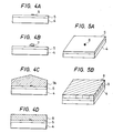
- Figs. 4A to 4D are illustrations of the formation steps showing a first embodiment of the method for forming crystal relating to the present invention
- Figs. 5A and 5B are perspective views of the substrates in Figs. 4A and 4D.
- a thin film 5 [deposition surface (S NDS )] with small nucleation density which enables selective deposition is formed and a material different from the material forming the thin film 5 with greater nucleation density is deposited thinly, followed by patterning according to lithography, etc., to form sufficiently finely deposition surface 6 (S NDL ) (or called "Seed”) comprising a different kind of material.
- S NDL deposition surface
- the size, the crystal structure and the composition of the substrate 4 may be any desired ones, and a substrate having a functional device formed thereon prepared according to conventional semiconductor technique may be employed.
- the deposition surface (S NDL ) 6 comprising a different kind of material is also inclusive of modified regions having excessive Si or N formed by ion injection of Si or N into the thin film 5 as described above.
- the deposition surface (S NDL ) 6 is required to be formed sufficiently finely so that only a single nucleus may be formed thereon.
- the nucleus grows while maintaining a single crystal structure to become a single crystal grain 7 in shape of an island as shown in Fig. 4B. For forming an island-shaped single crystal grain 7, it is desirable to determine the conditions so that no nucleation may occur at all on the thin film 5, as already mentioned.
- the island-shaped single crystal grain 7 further grows while maintaining the single crystal structure with the deposition surface (S NDL ) 6 as the center (lateral overgrowth), whereby it can cover over the whole thin film 5 as shown in Fig. 4C (single crystal 7A).
- the single crystal 7A is flattened by etching or polishing, and a single crystal layer 8 capable of forming a desired device can be formed on the thin film 5 as shown in Fig. 4D and Fig. 5B.
- any desired material can be used for the substrate 4 which is the supporting member. Further, in such a case, even when the substrate 4 may be one having a functional device, etc., formed thereon according to conventional semiconductor technique, the single crystal layer 8 can be easily formed thereon.
- the nonnucleation surface (S NDS ) is formed of thin film 5, but a substrate comprising a material with small nucleation density (ND) enabling selective nucleation may be used as such and nucleation surfaces (S NDL ) may be provided at any desired positions to form single crystal layers similarly thereon.
- ND small nucleation density
- Figs 6-1A 6-1D are illustrations of the formation steps showing a second embodiment of the method for forming crystal relating to the present invention
- Figs. 6-2A and 6-2B are perspective views of the substances in Figs. 6-1A and 6-1D.
- nucleation surfaces (S NDL ) 12-1, 12-2 of a material different from the substrate 11 enabling the above selective nucleation are arranged sufficiently finely.
- the distance l is set equal to the size of the single crystal region required for formation of semiconductor device or group of devices or greater.
- the nucleation surfaces (S NDL ) 12-1, 12-2 are required to be formed to a sufficiently fine size (area) to the extent that only a single nucleus may be formed.
- the size of the nuleatin surfaces (S NDL ) 12-1, 12-2, which may be different depending on the kind of the material, may be several microns or less.
- the nucleus grows while maintaining the single crystal structure, and become island-shaped single crystal grains 13-1, 13-2 as shown in Fig. 6-1B.
- the crystal direction in the normal line direction of the substrate 11 of the island-shaped single crystal grains 13-1, 13-2 is determined so as to make the interface energy of the material of the substrate 11 and the material forming nucleus minimum.
- surface or interface energy has anisotropy depending on the crystal face.
- the crystal direction within the substrate plane in amorphous substrate is not determined.
- the island-shaped single crystal grains 13-1, 13-2 further grow to become single crystals 13A-1, 13A-2 until the adjacent single crystals 13A-1, 13A-2 contact each other as shown in Fig. 6-1C, but since the crystal direction within the substrate plane is not constant, a crystal grain boundary 14 is formed at the intermediate position between the nucleation surfaces (S NDL ) 12-1 and 12-2.
- the single crystals 13A-1, 13A-2 grow three-dimensionally, but crystal faces with slow growth speed appear as the fact. For this reason, the surfaces of single crystals 13A-1, 13A-2 are flattened by etching or polishing, and further the portion of the grain boundary 14 is removed to form thin films of single crystals 15-1, 15-2 containing no grain boundary in shape of lattices as shown in Fig. 6-1D and Fig. 6B.
- the size of the single crystal films 15-1, 15-2, 15 is determined by the interval l between the nucleation surfaces (S NDL ) as described above. That is, by determining appropriately the formation pattern of the nucleation surface (S NDL ) 12, the position of the grain boundary can be controlled to form single crystals with desired sizes at a desired arrangement.
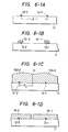
- Figs. 7A - 7D are illustration of the steps for forming crystal showing a third embodiment of the method for forming crystal relating to the present invention.
- a nonnucleation surface (S NDS ) 5 shaped in a thin film comprising a material with small nucleation density (ND) enabling selective nucleation is formed on a desired substrate 4, and a nucleation surfaces (S NDL ) 12 comprising a different material with greater nucleation density (ND) are formed at intervals of l thereon, whereby single crystal layers 15 can be formed similarly as in the above third embodiment.
- S NDS nonnucleation surface
- S NDL nucleation surfaces
- Figs. 8-1A - 8-1C are illustrations of the formation steps showing a fourth embodiment of the method for forming crystal relating to the present invention
- Figs. 8-2A and 8-2B are perspective views of the substances in Figs. 8-1A and 8-1C
- concavities 16 with desired size and shape are formed on the amorphous insulating substrate 11, and nucleation surfaces (S NDL ) 12 with sufficiently fine size for forming only single nucleus are formed therein.
- island-shaped single crystal grains 13 are grown similarly as in the first embodiment.
- single crystal grains 13 are grown until enbedding the concavity 16 to form a single crystal layer 17.
- Figs. 9A - 9C are steps for forming crystal showing a fifth embodiment of the present invention.
- a nonnucleation surface (S NDS ) shaped in thin film 18 comprising a material with samll nucleation density (ND) enabling selective nucleation is formed, and a concavity 16 with desired size and shape is formed thereon.
- a nucleation surface (S NDL ) 12 comprising a material different from the material forming the nonnucleation surface (S NDS ) with greater nucleation density (ND) is formed therein, and a single crystal layer 17 is formed similarly as in the fifth embodiment.
- Figs. 10A - 10D are illustrations of the steps for forming crystal showing an sixth embodiment of the present invention.
- Figs. 10A - 10C are the same as Figs. 6-1A - 6-1C. That is, a plurality (two in the Figure) of nucleation surfaces 12 are formed with an interval of l , and single crystal grains 13 subjected to overgrowth on the nucleation surfaces 12 are formed. By permitting the single crystal grains 13 to further grow to form single crystals 13A, a grain boundary 14 is formed approximately at the center between the nucleation surfaces (S NDL ), and by flattening the surface of single crystal 13A, a polycrystalline layer 21 with regular grains sizes which are approximately equal to l as shown in Fig. 10 can be obtained.
- S NDL nucleation surfaces
- the grain size of the polycrystalline layer 21 is determined by the interval l between the nucleation surfaces (S NDL ) 12, it becomes possible to control the grain size of the polycrystal.
- the grain size of a polycrystal was changed by a plural number of factors such as the formation method, formation temperature, etc., and also when preparing a polycrystal with large grain size, it had a grain size distribution with a considerable width.
- the grain size and grain size distribution can be determined with good controllability by the interval l between the nucleation surfaces 12.
- the above polycrystal layer 21 may be formed by forming a nonnucleation surface (S NDS ) 5 with small nucleation density (ND) on a desired substrate 4 and nucleation surfaces (S NDL ) 12-1, 12-2 with greater nucleation density (ND)
- S NDS nonnucleation surface
- S NDL nucleation surfaces
- ND nucleation density
- the substrate material and structure are not limited, but the polycrystal layer 21 can be formed by controlling the grain size and the grain size distribution.
- a substrate 11 is obtained with its surface being formed into nonnucleation surface (S NDS ).
- a quartz substrate which is a material with small nucleation density (ND) can be also used as the substrate 11, or alternatively nonnucleation surface (S NDS ) may be provided by forming SiO2 layer on the surface of any desired base substrate such as metal, semiconductor, magnetic material, piezoelectric material, insulator, etc., by use of the sputtering method, the CVD method, the vacuum vapor depostion method, etc.
- SiO2 is desirable, but SiO x (0 ⁇ x ⁇ 1) wi the value of x being varied may be also employed.
- silicon nitride layer e.g. Si3N4 layer
- a polycrystalline silicon layer e.g. Si3N4 layer
- the silicon nitride layer or polycrystalline silicon layer is subjected to patterning according to conventional lithographic technique or lithographic technique by use of X-ray, electron beam or ion beam, whereby nucleation surfaces (S NDL ) 12 having fine area of preferably 10 ⁇ m or less, more preferably several micron or less, optimully about 1 ⁇ m or less, are obtained.
- S NDL nucleation surfaces
- Si single crystal is selectively grown on the about substrate 11.
- the substrate temperature, pressure, etc. may be conveniently determined, but the substrate temperature may be preferably 700 to 1100°C, and the pressure may be preferably about 100 Torr.
- grains 13 of single crystals of Si grow on the nucleation surfaces (S NDS ) 12 comprising silicon nitride layer or polycrystalline silicon layer on the SiO2 layer as the center, and grow to sizes of some 10 ⁇ m or more.
- the surface of the single crystal 13A is flattened by selective etching of only Si, whereby a polycrystalline silicon layer 21 controlled in grain size can be formed (Fig. 10 D). Further, by removing the grain boundary portion, an island-shaped single crystalline silicon layer 15 is formed (Fig. 6-1D). If uneveness on the surface of the single crystal grain 13 is large, mechanical polishing may be conducted before etching.
- an electrical field effect transistor is formed according to conventional semiconductor device preparation technique on the single crystal silicon layer 15 thus formed with a size of some 10 ⁇ m or more containing no grain boundary, characteristics not inferior to that formed on single silicon wafer are exhibited.
- the thickness of the active layer of the device formed is thinner than the case when employing Si wafer, there is no erroneous actuation by the charges generated when radiation is irradiated. Further, due to lowering in unwanted capacity, speed-up of the device can be effected. Also, since any desired substrate can be used, a single crystal layer can be formed on a substrate of large area at lower cost than when employing Si wafer. Further, since a single crystal layer can be formed also on other semiconductors, piezoelectric materials, dielectric materials, etc., a multi-functional three-dimensional integrated circuit can be realized. Thus, the present invention exhibits a number of excellent effects.
- nucleation density difference between the material for formation of nonnucleation surface (S NDS ) and the material for formation of nucleation surface (S NDL ) as described above, for polycrystalline silicon or SiO2 as the material for formation of nonnucleation surface (S NDS ) to be used in combination, the material for formation of nucleation surface (S NDL ) is not limited to Si3N4, but silicon nitrides with various chemical composition ratios may be employed.
- the chemical composition ratio of silicon nitride may be varied as follows.
- the composition ratio of Si and N in the deposited silicon nitride film can be varied to a great extent.
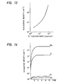
- Fig. 11 is a graph showing an example of the relationship between the flow rate ratio of SiH4 and NH3 and the composition ratio of Si and N in the silicon nitride film formed.
- the deposition conditions at this time were RF output of 175 W, substrate temperature of 380°C and the flow rate of NH3 gas was varied with the SiH4 gas flow rate being fixed at cc/min.
- the Si/N ratio in the silicon nitride film was found to be varied from 1.1 to 0.58 according to Auger's electron spectrophotometry.
- the silicon nitride film formed by heat treatment at about 1200°C in ammonia or N2 can be obtained with a composition further approximate to the stoichiometric ratio, since the formation method is performed under thermal equilibrium.
- the above nucleus of Si can be grown on the nucleation surface (S NDL ) comprising silicon nitride to form Si single crystal based on the nucleation density ( ⁇ ND) corresponding to the chemical composition ratio of silicon nitride.
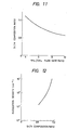
- Fig. 12 is a graph showing the relationship between Si/N composition ratio and nucleation density ( ⁇ ND). As shown in the same graph, by varying the chemical composition ratio of the silicon nitride film, the nucleation density of the Si single crystal nucleus formed thereon changes to a great extent.
- the nucleation conditions in the graph shown in Fig. 17 correspond to the case when Si single crystal nucleus was formed by reacting SiCl4 gas reduced to 175 Torr with H2 at 1000°C. Of course, another graph will be obtained if nucleation conditions such as gas species, pressure, temperature, etc., are changed.
- the phenomenon that the nucleation density thus changes according to the chemical composition ratio of silicon nitride affects the size (area) of the nucleation surface (S NDL ) when employing silicon nitride as the material for forming the nucleation surface (S NDL ) which is formed sufficiently finely to the extent that a single nucleus may be grown.
- nucleation surface (S NDL ) when employing silicon nitride having a composition with great nucleation density (ND) only a single crystal can be formed on the nucleation surface (S NDL ) by forming the nucleation surface (S NDL ) extremely finely as compared with the silicon nitride with relatively smaller nucleation density (ND).Such a point is applicable as a similar tendency for other materials for forming nucleation surface (S NDL ). Accordingly, in the present invention, for accomplishing its objects effectively, it is desirable to select a nucleation density (ND) and a size of nucleation surface (S NDL ) formed of silicon nitride, etc., capable of forming only a single crystal suitably as desired.
- ND nucleation density
- S NDL size of nucleation surface
- ND nucleation density
- S NDL nucleation surface
- ion injection of Si, N, P, B, F, Ar, He, C, As, Ga, Ge, etc. may be effected locally onto the surface comprising SiO2 which is a material for forming nonnucleation surface (S NDS ) with smaller nucleation density to form a modified region with a desired size on the SiO2 surface, and utilize this modified region as the nucleation surface (S NDL ) with greater nucleation density (ND).
- the SiO2 layer surface is covered with a photoresist layer and the desired portions are exposed, developed and dissolved to have the SiO2 layer surface exposed.
- SiF4 gas as the source gas, Si ions are implanted onto the SiO2 layer surface exposed at 10 keV at a density of 1 x 10¹⁶ ⁇ 1 x 1018 cm ⁇ 2.
- the projected flying distance in this case is 114 ⁇ , and the Si concentration on the exposed surface of SiO2 layer reaches about 1022 cm ⁇ 3 or less. Since the SiO2 layer is originally amorphous, the modified layer made excessively enriched in Si by injection of Si ions is also amorphous.
- ion injection can be effected with the use of a resist as the mask, but it is also possible to inject a narrowed Si ion beam selectively at a desired position on the SiO2 layer surface within a desired area without use of a resist mark by use of converged ion beam technique.
- Si-excessive modified region is formed on the SiO2 layer surface at a desired position with a desired size.
- Si single crystal is permitted to grow in vapor phase.
- Fig. 13 is a graph showing the relationship between amount of Si ions injected and nucleation density (ND).
- nucleation density is increased as the amount of Si+ injected is more.
- single crystal nuclei of Si can be formed with perfect selectivity on the fine silicon nitride regions permitted to exist in spots on the SiO2 layer, and single crystal Si can be grown thereon.
- the single crystal growth conditions as preferable example at this time may be, for example, a vacuum degree of 10 ⁇ 8 Torr or lower, Si beam intensity of 9.7 x 10¹⁴ atoms/cm2 ⁇ sec, and a substrate temperature of 900°C ⁇ 1000°C.
- nucleation surface (S NDL ) with high nucleation density (ND) tantalum oxide (Ta2O5), silicon nitride oxide (SiON), etc.
- ND high nucleation density
- Ta2O5 tantalum oxide
- SiON silicon nitride oxide
- a diamond single crystal can be easily grown on a material other than diamond substrate.
- explanation is made about an example of forming a single crystal of diamond by utilizing the fact that no single crystal nucleus of diamond grows on the surface of a metal such as Fe or Co.
- a metal layer of Fe or Co is formed by the vacuum vapor deposition method.
- the metaI layer becomes a polycrystalline structure.
- This metal layer forms the nonnucleation surface (S NDS ) with lower nucleation density (ND) as mentioned in the present specification.
- a metal such as Cu, W, Ta, Mo, Au, Ti, Al, Ni, etc.
- a semiconductor material such as Si, Ge, GaAs, InP, SiC, etc.
- this metal or semiconductor layer is subjected to patterning to a size of several micrometer to form a nucleation surface (S NDL ) with a suffficinetly fine area.
- the nucleation surface (S NDL ) comprising the above metal or semiconductor material may be formed by ion injection of the material as mentioned previously.
- diamond is crystallized on the metal layer where nucleation surface exists under the following conditions.
- the method for crystallization of diamond there may be employed the CVD method according to the microwave plasma CVD method, the hot filament method, etc.
- the starting gases for example, there may be employed gas mixtures of methane (CH4) and hydrogen (1 ⁇ 10 %), or hydrocarbons having alcoholic OH groups, specifically methyl alcohol CH3OH, ethyl alcohol C2H5OH, tert-butyl alcohol (CH3)3OH, isopropyl alcohol (CH3)2CHOH, diethyl ether C2H5OC2H5, etc., by bubbling these liquids with hydrogen gas.
- the plasma CVD method it can be practiced, for example, under the conditions of a microwave output of 200 to 350 W, a substrate temperature of 500 to 1000°C and a reduced pressure of 1 to 400 Torr.
- the CVD method by use of the hot filament method, it can be practiced, for example, under the conditions of a filament temperature of about 1500 to 2000°C and a filament-substrate distance of 0.5 to 10 mm.
- Fig. 14 is a graph showing the time dependency of nucleation density of the diamond on the surface of Fe, Co, Si, Mo.
- the base substrate it may be a substrate of the material capable of forming the above nonnucleation surface (S NDS ), and therefore the selection scope can be broadened to a great extent to accomplish low cost and enlargement of area with ease.
- S NDS nonnucleation surface
- Tungsten has been known to effect no nucleation on the surface of SiO2 layer, but to be deposited as a polycrystalline film on Si, WSi2, PtSi, Al, etc.
- the substrate such as glass composed mainly of SiO2, quartz, SiO2 hot oxide film (all of these form nonnucleation surface (S NDS )
- Si, WSi2, PtSi or Al is deposited by vacuum vapor deposition, and subjected to patterning to a size of several ⁇ m or less by photolithography to form a desired number of nucleation surfaces (S NDL ).
- the above substrate is placed in, for example, a reaction furnace heated to 250 ⁇ 500°C, and a gas mixture of WF6 gas and hydrogen gas is permitted to flow under a reduced pressure of about 0.1 to 10 Torr, at the respective flow rates of 75 cc/min and 10 cc/min.
- tungsten is formed as represented by the reaction scheme WF6 + 3H2 ⁇ W + 6HF.
- the reactivity of tungsten with SiO2 is extremely low to give no firm bonding, and therefore no nucleation occurs on the SiO2 surface and hence no deposition is effected.
- nucleation surface (S NDL ) formed of Si, WSi2, PtSi, Al, etc. single crystal nuclei of tungsten are formed single crystal nuclei of tungsten singly, because nucleation surfaces (S NDL ) are formed finely. And, the single crystal of tungsten continues to grow and also grows as such single crystal also in the lateral direction on SiO2. This is because nonnucleus growth of tungsten occurs on SiO2, whereby no polycrystal is formed by interference of single crystal growth.
- nonnucleation surface (S NDS ) forming material, nucleation surface (S NDL ) forming material and crystal forming material as described above is not limited to those shown in the above embodiments, but it may be clearly a combination of materials having sufficent nucleation density difference. Accordingly, also in the case of a compound semiconductor capable of selective nucleation such as GaAs, InP, etc., a single crystal, a group of single crystals or a polycrystal controlled in grain size and grain size distribution can be formed according to the present invention.
- Fig. 15 is a schematic illustrative sectional view showing a multi-layer structure semiconductor device according to a first embodiment of the present invention.
- a layer 1502 having a deposition surface (S NDS ) formed of small nucleation density material is formed on a substrate 1501 in which electronic element such as transistor 1503 or the like is formed.
- S NDL deposition surface
- nucleation surface [the deposition surface (S NDL )] 1504 having sufficiently small area and being formed of greater nucleation density is located at a predetermined interval described as follows.
- Single crystal is grown with the surface 1504 as a center.
- Plurality of single crystal layers 1505 like an island are formed.
- thin film transistor 1506 is formed on each single crystal layer 1505, for example, in the present embodiment. Since the layer 1502 on which the transistor is formed is the insulating layer, the transistor has small parasitic capacitance therefore achieves high speed operation.
- the transistor 1503 for example, p-channel or n-channel MOS transistor is formed in the first layer (substrate) 1501 by conventional semiconductor process technique.
- the single crystal layer 1505 of semiconductor material such as silicon or the like is formed by above described crystal producing technique.
- the single crystal layer 1505 can be formed as follow.
- P type impurity is injected into the single crystal layer 1505 by ion implantation technique or the like to selectively form P type semiconductor layers 1507 and 1509.
- n-type semiconductor layer 1508 is selectively formed.
- the single crystal layer 1505 in which npn junction is formed is covered with electrically insulating layer 1510 such as SiO2 or the like over the surface.
- electrically insulating layer 1510 such as SiO2 or the like over the surface.
- the insulating layer of the P type semiconductor layer 1507, 1509 is removed at predetermined position to expose the P type semiconductor layers 1507, 1509.
- electrodes 1510, 1512 formed of metal such as Al or the like are provided.
- a gate electrode 1506 is formed of metal such as Al or the like.
- n-channel MOS transistor p-channel MOS transistor
- the conductivity type of the semiconductor materials used in the above processing are reversed. That is, the n type and p type semiconductor layers are altered respectively to p type and n type semiconductor layers.
- Fig. 16 is a schematic illustrative sectional view showing a multi-layer structure semiconductor device according to a second embodiment of the present invention.
- a layers 1603 having deposition surfaces (S NDS ) formed by small nucleation density material is formed on a substrate 1602 as a first layer in which electronic elements such as transistor 1601 or the like are formed.
- S NDS deposition surfaces
- a nucleation surface 1605 [a deposition surface (S NDL )] having sufficiently small area and being formed of greater nucleation density material is formed.
- a single crystal layer 1606 is formed with nucleation surface 1605 as a center to fill and flatten the concave portion.
- a second layer in which electronic element such as transistor 1607 or the like is formed is formed by conventional semiconductor processing.
- a third layer 1608, a fourth layer,...etc, can be produced by the same process as the second layer producing process.
- polycrystalline layer can be formed on the layer 1608 having deposition surface (S NDS ) if desired.
- the multi-layer structure semiconductor device as shown in Fig. 16 is a three dimensional semiconductor device with more than three layers (In Fig. 16, the embodiment of only two layers in which electronic elements are incorporated is shown.).
- the electronic element 1601 for example MOS transistor is formed as desired by conventional silicon semiconductor process technique.
- the second layer 1603 of insulating material such as SiO2 or the like by PCVD process, sputtering process or the like technique.
- concave portion 1604 of desired size is formed by selective etching process.
- the nucleation surface 1605 is formed.
- the single crystal layer 1606 such as single crystal silicon or the like is formed in the concave portion 1604 with the nucleation surface 1605 as a center.
- an electronic element 1607 for example, n-channel or p-channel MOS transistor is formed by conventional semiconductor process technique.
- n type semiconductor regions 1609, 1610 are formed in the p type semiconductor region by ion implantation or diffusion process.
- Preliminary provided insulating oxide film such as SiO2 or the like is removed at positions over the n type semiconductor regions 1609, 1610 At the positions, the electrodes 1611, 1612 formed of metal such as Al or the like are provided.
- the gate electrode 1613 formed of metal such as Al or the like is provided on the insulating oxide film over the p-channel portion.
- the electronic element 1607 is formed in the second layer 1603.
- the third layer 1608 is formed by a process like the second layer producing process.
- electronic element is formed like the second layer 1603.
- Fig. 17 is a schematic illustrative sectional view showing a semiconductor device according to a third embodiment of the present invention.
- the substrate 1701 is made of desired materials such as semiconductor material and insulating material such as quartz, ceramic, or the like.
- an insulating layer 1702 formed of material having small nucleation density for growing the silicon is provided on a substrate 1701.
- n-channel MOS transistor 1703 and p-channel MOS transistor 1704 are formed on the insulating layer 1702. They constitute C-MOS. Producing process of transistors 1703 and 1704 is described as follows.
- a material (Silicon nitride is used in the present embodiment.) of greater nucleation density than SiO2 is provided.
- the material is patterned to have a sufficiently small area approximately 1.0 ⁇ m square. Thereby, a nucleation region 1705 is formed. Further, the nucleation region 1705 may be formed by ion implantation as described in the above.
- single crystal silicon is grown with the nucleation region 1705 as a center at 700 ⁇ 1000°C by using Hz gas as a carrier and SiHCl4, SiHCl3, etc. Such grown single crystal silicon is flattened to form a single crystal silicon layer 1706 like island.
- p type impurity ion and n type impurity ion are respecitvely independently implanted into a single crystal silicon layer 1706 in which a transistor 1703 is formed and a single crystal silicon 1706 in which a transistor 1704 is formed.
- a gate insulating film 1707 is formed on each single crystal silicon layer 1704. Further gate electrode 1708 of polycrystal silicon is formed by patterning. Next, n type impurity ion and p type impurity ion are implanted respectively into the transistor 1703 side and the transistor 1704 side by using the gate electrode 1708 as a mask. During next heating process, n diffusion regions 1711, 1712, and p diffusion regions 1714, 1715 are formed as source ⁇ drain region.
- p-channel region 1713 and n-channel region 1716 are also formed.
- source ⁇ drain electrodes 1709 and 1710 and wiring are formed.
- n-channel MOS transistor 1703 and p-channel MOS transistor 1704 constituting C-MOS are formed.
- MOS transistor has much smaller floating capacitance of sorce and drain than that of conventional pn junction type one.
- channel mobility for n-channel MOS transistor 1703 is greater than 400 cm2/V ⁇ sec.
- channel mobility for p-channel MOS transistor 1704 is greater than 200 cm2/v ⁇ sec. The mobility is approximated the same value as that of a transistor formed on a silicon wafer. This fact proves that high quality single crystal silicon is obtained by the above selective crystal growth.
- MOS transistors are provided. to constitute C-MOS in the present embodiment, of cource, the present invention is not limited to the C-MOS embodiment.
- independently provided MOS transistor can be produced.
- the present invention is applicable not limited to MOS transistor but to any insulated gate type transistor suitable for large scale integration.
- Fig. 18 is a schematic illustrative sectional view showing a fourth embodiment of the present invention.
- MOS transistor can be produced by forming an inter-layer insulating layer 1802 of SiO2 on an underlayer 1801 in which MOS transistor is formed, and conducting a process like that for producing the under layer 1801. Further, a contact hole through the inter-layer insulating layer 1802 is formed. MOS transistor 1803 is connected via the hole to MOS transistor 1804 in the underlayer. By repeating such process, three dimensional integration with more than two layers can be readily produced.
- n-channel and p-channel transistors can be formed in different layers respectively.
- the single crystal silicon layer is formed at low temperature approximately 700 ⁇ 1000°C, no performance deterioration of underlayer element is caused.
Abstract
Description
- The present invention relates to a semiconductor device with crystalline layer formed by utilizing selective nucleation method for selectively growing crystal using a difference in nucleation density of the deposited film forming materials according to the kinds of the deposited surface constituting materials.
- Since an integrated circuit device comprising an integrated circuit produced by forming a single crystal silicon on an insulating material substrate has small parasitic capacitance, it can operate in higher speed then the integrated circuit formed on a silicon substrate. Further, when a complementary MOS (C-MOS) integrated circuit is produced by the single crystalline silicon formed on the insulating material substrate, since no thyristor is formed by a parasitic bipolar transistor, there is no possibility of causing a latch up effect.
- As the insulating material substrate for use in such integrated circuit device, a sapphire substrate has been used conventionally.
- However, the sapphire substrate is more expensive than the silicon substrate very much. The sapphire substrate is applicable for only a limited use.
- Further, in recent years, method for forming a single crystalline film by covering the silicon substrate with insulating material, forming polycrystalline silicon film on the insulating material, and melting and recrystallizing the polycrystalline silicon with laser beam, and method for obtaining structure wherein the single crystalline silicon layer is on the insulating layer by implanting oxygen ion into the silicon substrate to form the insulating layer in the silicon substrate.
- However, all of these methods require process of very low producing efficiency such as process for melting the polycrystalline silicon with laser beam and process of high dose ion implantation with ion implantation apparatus. Accordingly, there are problems that reducing the cost of the integrated circuit device is difficult and that, since it is difficult to get a high quality single crystalline silicon, high performance integrated circuit can not be produced. While, in recent years, studying and development of three dimensional integrated circuit, wherein semiconductor elements are formed in a configuration of layers stacked on the substrate is a direction normal to the substrate thereby high integration density and multifunction are achieved, are executed.
- In order to achieve the three dimensional integrated circuit, it is necessary to form the semiconductor thin film for producing the electronic elements such as transistors on amorphous insulating material. However, in general, on the amorphous material, only amorphous silicon or polycrystalline silicon can be grown.
- Therefore, in the prior art methods are classified as method wherein the amorphous or polycrystalline silicon is directly used as the semiconductor layers for producing the electronic elements, or method wherein the grown amorphous or polycrystalline silicon is method with laser beam or the like to be crystallized as a single crystal and the crystallized single crystal is used as the semiconductor layers of the electronic element.
- However, when the amorphous or polycrystalline silicon is directly used as a semiconductor layer for producing the electronic elements, there are problems that the electron mobilities obtained is small (approximately ∼0.1 cm²/V·sec for amorphous; approximately 1 ∼10 cm²/V·sec for polycrystalline silicon with particle size of few hundreds of angstroms), and that leak current is large even if PN junction is formed. Accordingly, high performance electronic elements can not be produced.
- While, according to the method wherein the grown amorphous or polycrystalline silicon is melted and re-crystallized, since the single crystal layer is used as the semiconductor layer for producing the electronic elements, high performance electronic elements can be obtained. However, since the silicon layer is heated by the laser beam to be melted, there is a problem that the heating adversely affects the performance of the elements formed under the silicon layer.
- An object of the present invention is to provide the semiconductor device and method for producing the same wherein the problems of the prior art as described in the above are solved.
- Another object of the present invention is to provide multi-layer structure semiconductor device with high performance elements using single or polycrystal, and method for producing the same easily and with high reliability.
- Further object of the present invention is to provide a semiconductor device and a method for producing the same wherein, on an underlayer wherein desired elements and/or wirings are formed, a layer with deposition surface is formed directly on the underlayer or in the configuration of sandwiching another layer therebetween the underlayer and the layer with deposition surface. On the deposition surface (SNDS), a deposition surface (SNDL) of a material having sufficiently greater nucleation density than the nucleation density of a material forming the deposition surface (SNDS) and being sufficiently fine so that only single nucleus is grown is provided. In a crystalline layer grown from the single nucleus grown on the deposition surface (SNDL), at least a desired element is formed.
- Still further object of the present invention is to provide a semiconductor device and method for producing the same. The semiconductor device has an insulated gate type transistor. The insulated gate type transistor is formed on a surface of the insulating material, the surface of which is at least insulating. A single crystal layer forming the insulated gate type transistor is produced by providing nucleation base having sufficiently greater nucleation density than the insulating material and being sufficiently fine so that only one nucleus is grown, and growing the single crystal from the one nucleus grown on the nucleation base.
-
- Fig. 1 is a graph for illustration of the relationship between the size of nucleus rc and free energy G in the process of forming thin film;
- Figs. 2A and 2B are illustrations of the selective deposition method;
- Fig. 3 is a graph showing the change with lapse of time of nucleation density (ND) on the deposition surface of SiO₂ and the deposition surface of silicon nitride;
- Figs. 4A to 4D are illustrations of the formation steps showing a first embodiment of the method for forming crystal relating to the present invention;
- Figs. 5A and 5B are perspective views of the substrate in Figs. 4A to 4D;
- Figs. 6-1A to 6-1D are illustrations of the formation steps showing a second embodiment of the method for forming single crystal relating to the present invention;
- Figs. 6-2A and 6-2B are perspective views of the substrates in Figs. 6-1A to 6-1D;
- Figs. 7A to 7D are illustrations of the steps for forming crystal showing a third embodiment of the method for forming crystal relating to the present invention;
- Figs. 8-1A to 8-1C are illustrations of formation steps showing a fourth embodiment of the method for forming crystal relating to the present invention;
- Figs. 8-2A and 8-2B are perspective views of the substrates in Figs. 8-1A to 8-1C;
- Figs. 9A to 9C are illustrations of the steps for forming crystal showing a fifth embodiment of the method for forming crystal relating to the present invention;
- Figs. 10A to 10D are illustrations of the steps for forming crystal showing a sixth embodiment of the method for forming crystal relating to the present invention;
- Fig. 11 is a graph showing the relationship between the flow rate of SiH₄ and NH₃ and the composition ratio of Si and N in the silicon nitride film formed;
- Fig. 12 is a graph showing the relationship between Si/N composition ratio and nucleation density;
- Fig. 13 is a graph showing the relationship between the injected amount of Si ions and nucleations density;
- Fig. 14 is a graph showing the time dependency of nucleation density of diamond nuclei on Fe, Co, Si and Mo.
- Fig. 15 is a schematic illustrative sectional view showing a multi-layer structure semiconductor device according to a first embodiment of the present invention;
- Fig. 16 is a schematic illustrative sectional view showing a multi-layer structure semiconductor device according to a second embodiment of the present invention;
- Fig. 17 is a schematic illustrative sectional view showing a semiconductor device according to a third embodiment of the present invention; and
- Fig. 18 is a schematic illustrative sectional view showing a fourth embodiment of the present invention.
- For better understanding of the present invention, first the general process for forming a thin film of metal for semiconductor is explained.
- When the deposition surface is made of a material different in kind from the flying atom, particularly an amorphous material, the flying atoms are diffused freely on the substrate surface, or again evaporated (released). And, as the result of collision mutually between the atoms, a nucleus is formed and when its size becomes the size rc (= -2 σo/gv) at which its free energy G becomes the maximum (critical nucleus), G is reduced and the nucleus continues to grow stably three-dimensionally to become shaped in an island. The nucleus with the size exceeding rc is called stable nucleus, and unless otherwise particularly noted, "nucleus" in the following basic description of the present invention refers to this "stable nucleus". Also, among "stable nucleus", those with small r are called "initial nucleus".
- The free energy generated by formation of nucleus is represented as follows:
G = 4πf(ϑ)(σo r² +1/3·gv·r³)
f(ϑ) = 1/4(2 - 3cosϑ + cos²ϑ)
wherein, r: radius curvature of nucleus
ϑ: contact angle of nucleus
gv: free energy per unit deposition
σo: surface energy between nucleus and vacuum.
Fig. 1 shows the manner in which G is changed. In the same Figure, the radius of curvature of the stable uncleus when G is at the maximum value is rc. - Thus, nuclei grow to become shaped in islands, and further grow whereby contact mutually between islands progresses until sometimes coalescence occurs and via a network structure, it becomes finally a continuous film to cover completely over the substrate surface. Following such a process, a thin film is deposited on the substrate.
- In the deposition process as described above, the density of nucleus formed per unit area of the substrate surface, the size of nucleus and the nucleation speed are determined depending on the state of the system of deposition, and particularly the interaction between the flying atoms and the substrate surface material is an important factor. Also, a specific crystal direction grows in parallel to the substrate due to anisotropy relative to the crystal surface of the interface energy at the interface between the deposited material and the substrate, and when the substrate is amorphous, the crystal direction within the substrate plane is not constant. For this reason, grain boundaries are formed by collision mutually between nuclei or islands, and particularly in the case of collision mutually between islands with some sizes or greater, grain boundaries are formed as such rather than occurrence of coalescence. Since the grain boundaries formed are difficulty movable in the solid phase, the grain sizes are determined at that point.
- Next, the selective deposition method for forming a deposited film selectively on the deposition surface is to be described. The selective deposition method is a method in which a thin film is formed selectively on the substrate by utilizing the differences between the materials in factors influencing nucleus formation in the thin film forming process such as surface energy, attachment coefficient, release coefficinet, surface diffusion speed, etc.
- Figs. 2A and 2B are illustrations of the selective deposition method. First, as shown in Fig.2A on the
substrate 1, athin film 2 comprising a material different in the above factors from thesubstrate 1 is formed at a desired portion. And, when deposition of a thin film comprising an appropriate material is effected under appropriate deposition conditions, a thin film 3 grows only on thethin film 2, whereby it is possible to give rise to a phenomenon that no growth occurs on thesubstrate 1. By utilizing this phenomenon, the thin film 3 formed self-matchingly can be grown, whereby it becomes possible to omit the lithographic step by use of a resist as practiced in the prior art. - As the material for enabling deposition according to such selective formation method, for example, SiO₂ may be used as the
substrate 1, Si, GaAs, silicon nitride as thethin film 2 and Si, W, GaAs, InP, etc., as the thin film 3 to be deposited. - Fig. 3 is a graph showing the change with lapse of time of nucleation density on the deposited surface of SiO₂ and the deposited surface of silicon nitride.
- As shown in the same graph, soon after initiation deposition, the nucleation density on SiO₂ is saturated at 10³ cm⁻² or less, and the value is not substantially changed even after 20 minutes.
- In contrast, on silicon nitride (Si₃N₄), it is once saturated at about 4 x 10⁵ cm⁻² or less, is not substantially changed 10 minutes thereafter, but is abruptly increased thereafter. This measurement example shows the case in which SiCl₄ gas is diluted with H₂ and deposited according to the CVD method under the conditions of a pressure of 170 Torr and a temperature of 1000°C. Otherwise, the same action can be obtained by use of SiH₄, SiH₂Cl₂, SiHCl₃, SiF₄, etc., as the reaction gas, and controlling the pressure, temperature, etc. Also, the vacuum vapor deposition can be employed.
- In this case, nucleation on SiO₂ poses substantially no problem, but by addition of HCl gas into the reaction gas, nucleation on SiO₂ can be further suppressed to make deposition of Si on SiO₂ perfectly zero.
- Such a phenomenon depends greatly on the difference in adsorption coefficinet, release coefficient, surface diffusion coefficinet, etc., relative to Si of the material surfaces of SiO₂ and silicon nitride, but the fact that SiO₂ itself is etched by the reaction of SiO₂ with Si atom itself to form silicon monooxide with higher vapor pressure, while no such etching phenomenon occurs on silicon nitride may be also considered to be a cause to effect selective deposition (T. Yonehara, S. Yoshioka, S. Miyazawa, Journal of Applied Physics 53, 6839, 1982).
- Thus, by selecting SiO₂ and silicon nitride as the materials of the deposition surface and silicon as the material to be deposited, sufficiently great nucleation density difference as shown in the same graph can be obtained. Here, although SiO₂ is desirable as the material for the deposition surface, this is not limitative and sufficiently practical nucleation density difference can be obtained even by use of SiOx (0 < x < 2).
- Of course, the present invention is not limited to these materials, but the difference in nucleation density (ΔND) may be sufficinetly 10³-fold or more in density of nuclei as shown by the same graph, and sufficient selective formation of deposited film can be done with the materials as examplified below.
- As another method for obtaining this nucleation density difference (ΔND), ions of Si or N may be injected locally into the SiO₂ surface to form a region having excessive Si or N.
- The present invention utilizes selective deposition based on such nucleation density difference (ΔND) and, by forming sufficiently finely so that a single nucleus may grow on the deposition surface of a different kind of material having sufficiently greater nucleation density than the material of the deposition surface, a single crystal can be grown selectively only at the site where such fine different kind of material exists.
- In this connection, since selective growth of a single crystal is determined depending on the electron state of the deposition surface, particularly the state of dangling bonds, the material with lower nucleation density (for example, SiO₂) is not required to be a bulk material, but it may be formed only on the surface of any desired material, substrate, etc., to form the above deposited surface.
- In the following, the present invention is described in detail by referring to the drawings.
- Figs. 4A to 4D are illustrations of the formation steps showing a first embodiment of the method for forming crystal relating to the present invention, and Figs. 5A and 5B are perspective views of the substrates in Figs. 4A and 4D. First, as shown in Fig. 4A and Fig. 5A, on the
substrate 4, a thin film 5 [deposition surface (SNDS)] with small nucleation density which enables selective deposition is formed and a material different from the material forming thethin film 5 with greater nucleation density is deposited thinly, followed by patterning according to lithography, etc., to form sufficiently finely deposition surface 6 (SNDL) (or called "Seed") comprising a different kind of material. However, the size, the crystal structure and the composition of thesubstrate 4 may be any desired ones, and a substrate having a functional device formed thereon prepared according to conventional semiconductor technique may be employed. Also, the deposition surface (SNDL) 6 comprising a different kind of material is also inclusive of modified regions having excessive Si or N formed by ion injection of Si or N into thethin film 5 as described above. - Next, by selection of appropriate deposition conditions, a single crystal of a thin film material is formed only on the deposition surface (SNDL) 6. That is, the deposition surface (SNDL) 6 is required to be formed sufficiently finely so that only a single nucleus may be formed thereon. The size of the deposition surface (SNDL) 6, which may differ depending on the kind of the material, may be several microns or less. Further, the nucleus grows while maintaining a single crystal structure to become a
single crystal grain 7 in shape of an island as shown in Fig. 4B. For forming an island-shapedsingle crystal grain 7, it is desirable to determine the conditions so that no nucleation may occur at all on thethin film 5, as already mentioned. - The island-shaped
single crystal grain 7 further grows while maintaining the single crystal structure with the deposition surface (SNDL) 6 as the center (lateral overgrowth), whereby it can cover over the wholethin film 5 as shown in Fig. 4C (single crystal 7A). - Subsequently, if necessary, the
single crystal 7A is flattened by etching or polishing, and asingle crystal layer 8 capable of forming a desired device can be formed on thethin film 5 as shown in Fig. 4D and Fig. 5B. - For forming thus the
thin film 5 forming the nonnucleation surface (SNDS) on thesubstrate 4, any desired material can be used for thesubstrate 4 which is the supporting member. Further, in such a case, even when thesubstrate 4 may be one having a functional device, etc., formed thereon according to conventional semiconductor technique, thesingle crystal layer 8 can be easily formed thereon. - In the above embodiment, the nonnucleation surface (SNDS) is formed of
thin film 5, but a substrate comprising a material with small nucleation density (ND) enabling selective nucleation may be used as such and nucleation surfaces (SNDL) may be provided at any desired positions to form single crystal layers similarly thereon. - Figs 6-1A 6-1D are illustrations of the formation steps showing a second embodiment of the method for forming crystal relating to the present invention, and Figs. 6-2A and 6-2B are perspective views of the substances in Figs. 6-1A and 6-1D.
- As shown in Fig. 6-1A and 6-2A, on the amorphous insulating
substrate 11, with an interval of a distance ℓ, nucleation surfaces (SNDL) 12-1, 12-2 of a material different from thesubstrate 11 enabling the above selective nucleation are arranged sufficiently finely. The distance ℓ is set equal to the size of the single crystal region required for formation of semiconductor device or group of devices or greater. - Next, by selecting appropriate crystal forming conditions, on the nucleation surfaces (SNDL) 12-1, 12-2 only a nucleus of a crystal forming naterial is formed. That is, the nucleation surfaces 12-1, 12-2 are required to be formed to a sufficiently fine size (area) to the extent that only a single nucleus may be formed. The size of the nuleatin surfaces (SNDL) 12-1, 12-2, which may be different depending on the kind of the material, may be several microns or less. Further, the nucleus grows while maintaining the single crystal structure, and become island-shaped single crystal grains 13-1, 13-2 as shown in Fig. 6-1B. For forming island-shaped single crystal grains 13-1, 13-2, it is desirable to determine the conditions so that no nucleation may occur at all on other surfaces than the nucleation surfaces (SNDL) on the
substrate 11. - The crystal direction in the normal line direction of the
substrate 11 of the island-shaped single crystal grains 13-1, 13-2 is determined so as to make the interface energy of the material of thesubstrate 11 and the material forming nucleus minimum. For, surface or interface energy has anisotropy depending on the crystal face. However, as already mentioned, the crystal direction within the substrate plane in amorphous substrate is not determined. - The island-shaped single crystal grains 13-1, 13-2 further grow to become
single crystals 13A-1, 13A-2 until the adjacentsingle crystals 13A-1, 13A-2 contact each other as shown in Fig. 6-1C, but since the crystal direction within the substrate plane is not constant, acrystal grain boundary 14 is formed at the intermediate position between the nucleation surfaces (SNDL) 12-1 and 12-2. - Subsequently, the
single crystals 13A-1, 13A-2 grow three-dimensionally, but crystal faces with slow growth speed appear as the fact. For this reason, the surfaces ofsingle crystals 13A-1, 13A-2 are flattened by etching or polishing, and further the portion of thegrain boundary 14 is removed to form thin films of single crystals 15-1, 15-2 containing no grain boundary in shape of lattices as shown in Fig. 6-1D and Fig. 6B. The size of the single crystal films 15-1, 15-2, 15 is determined by the interval ℓ between the nucleation surfaces (SNDL) as described above. That is, by determining appropriately the formation pattern of the nucleation surface (SNDL) 12, the position of the grain boundary can be controlled to form single crystals with desired sizes at a desired arrangement. - Figs. 7A - 7D are illustration of the steps for forming crystal showing a third embodiment of the method for forming crystal relating to the present invention. As shown in these figures, similarly as in the first embodiment, a nonnucleation surface (SNDS) 5 shaped in a thin film comprising a material with small nucleation density (ND) enabling selective nucleation is formed on a desired
substrate 4, and a nucleation surfaces (SNDL) 12 comprising a different material with greater nucleation density (ND) are formed at intervals of ℓ thereon, whereby single crystal layers 15 can be formed similarly as in the above third embodiment. - Figs. 8-1A - 8-1C are illustrations of the formation steps showing a fourth embodiment of the method for forming crystal relating to the present invention, and Figs. 8-2A and 8-2B are perspective views of the substances in Figs. 8-1A and 8-1C First, as shown in Fig.8-1A and Fig.8-2A,
concavities 16 with desired size and shape are formed on the amorphous insulatingsubstrate 11, and nucleation surfaces (SNDL) 12 with sufficiently fine size for forming only single nucleus are formed therein. - Subsequently, as shown in Fig. 8-1, island-shaped
single crystal grains 13 are grown similarly as in the first embodiment. - And, as shown in Fig. 8-1C and Fig. 8-2B,
single crystal grains 13 are grown until enbedding theconcavity 16 to form asingle crystal layer 17. - In this embodiment, since
single crystal grains 13 flow within theconcavity 16, the steps of flattening and removing the grain portion become unnecessary. - Figs. 9A - 9C are steps for forming crystal showing a fifth embodiment of the present invention. As shown in the same Figure, on any desired
substrate 4 similarly as in the first embodiment, a nonnucleation surface (SNDS) shaped inthin film 18 comprising a material with samll nucleation density (ND) enabling selective nucleation is formed, and aconcavity 16 with desired size and shape is formed thereon. And, a nucleation surface (SNDL) 12 comprising a material different from the material forming the nonnucleation surface (SNDS) with greater nucleation density (ND) is formed therein, and asingle crystal layer 17 is formed similarly as in the fifth embodiment. - Figs. 10A - 10D are illustrations of the steps for forming crystal showing an sixth embodiment of the present invention.
- Figs. 10A - 10C are the same as Figs. 6-1A - 6-1C. That is, a plurality (two in the Figure) of nucleation surfaces 12 are formed with an interval of ℓ, and
single crystal grains 13 subjected to overgrowth on the nucleation surfaces 12 are formed. By permitting thesingle crystal grains 13 to further grow to formsingle crystals 13A, agrain boundary 14 is formed approximately at the center between the nucleation surfaces (SNDL), and by flattening the surface ofsingle crystal 13A, apolycrystalline layer 21 with regular grains sizes which are approximately equal to ℓ as shown in Fig. 10 can be obtained. - Since the grain size of the
polycrystalline layer 21 is determined by the interval ℓ between the nucleation surfaces (SNDL) 12, it becomes possible to control the grain size of the polycrystal. In the prior art, the grain size of a polycrystal was changed by a plural number of factors such as the formation method, formation temperature, etc., and also when preparing a polycrystal with large grain size, it had a grain size distribution with a considerable width. However, according to the present invention, the grain size and grain size distribution can be determined with good controllability by the interval ℓ between the nucleation surfaces 12. - Of course, as shown in Fig. 9, the
above polycrystal layer 21 may be formed by forming a nonnucleation surface (SNDS) 5 with small nucleation density (ND) on a desiredsubstrate 4 and nucleation surfaces (SNDL) 12-1, 12-2 with greater nucleation density (ND) In this case, as already mentioned, the substrate material and structure are not limited, but thepolycrystal layer 21 can be formed by controlling the grain size and the grain size distribution. - Next, the specific method for forming a single crystal layer or a polycrystal layer in the above respective embodiments is described in more detail by referring primarily to the third embodiment shown in fig. 6-1 and the eigth embodiment shown in Fig. 10.
- By thermal oxidation of a Si single crystal wafer to form SiO₂ on the surface, a
substrate 11 is obtained with its surface being formed into nonnucleation surface (SNDS). Of course, a quartz substrate which is a material with small nucleation density (ND) can be also used as thesubstrate 11, or alternatively nonnucleation surface (SNDS) may be provided by forming SiO₂ layer on the surface of any desired base substrate such as metal, semiconductor, magnetic material, piezoelectric material, insulator, etc., by use of the sputtering method, the CVD method, the vacuum vapor depostion method, etc. Also, as the material forming nonnucleation surface (SNDS), SiO₂ is desirable, but SiOx (0 < x < 1) wi the value of x being varied may be also employed. - On the SiO₂ layer of the
substrate 11 having SiO₂ layer thus formed on the surface is deposited as silicon nitride layer (e.g. Si₃N₄ layer) or a polycrystalline silicon layer according to the reduced pressure chemical vapor deposition method, and subsequently the silicon nitride layer or polycrystalline silicon layer is subjected to patterning according to conventional lithographic technique or lithographic technique by use of X-ray, electron beam or ion beam, whereby nucleation surfaces (SNDL) 12 having fine area of preferably 10 µm or less, more preferably several micron or less, optimully about 1 µm or less, are obtained. - Subsequently, by use of SiH₂Cl₂, SiCl₄, SiHCl₃, SiF₄ or SiH₄, or a gas mixture of these, optionally mixed with HCl, H₂ or a gas mixture of these, Si single crystal is selectively grown on the about
substrate 11. - The substrate temperature, pressure, etc., may be conveniently determined, but the substrate temperature may be preferably 700 to 1100°C, and the pressure may be preferably about 100 Torr.
- Within a time of about some 10 minutes, by selection of optimum growth conditions,
grains 13 of single crystals of Si grow on the nucleation surfaces (SNDS) 12 comprising silicon nitride layer or polycrystalline silicon layer on the SiO₂ layer as the center, and grow to sizes of some 10 µm or more. - Subsequently, by the reactive ion etching (RIE) method utilizing the etching speed difference between Si and SiO₂, the surface of the
single crystal 13A is flattened by selective etching of only Si, whereby apolycrystalline silicon layer 21 controlled in grain size can be formed (Fig. 10 D). Further, by removing the grain boundary portion, an island-shaped singlecrystalline silicon layer 15 is formed (Fig. 6-1D). If uneveness on the surface of thesingle crystal grain 13 is large, mechanical polishing may be conducted before etching. When an electrical field effect transistor is formed according to conventional semiconductor device preparation technique on the singlecrystal silicon layer 15 thus formed with a size of some 10 µm or more containing no grain boundary, characteristics not inferior to that formed on single silicon wafer are exhibited. - Also, mutual interference between the adjacent single crystal silicon layers 15 can be prevented, if they are electrically separated by an electrical insulator such as SiO₂, even if a complementary type electrical field effect transistor (C-MOS) may be constituted.
- Also, since the thickness of the active layer of the device formed is thinner than the case when employing Si wafer, there is no erroneous actuation by the charges generated when radiation is irradiated. Further, due to lowering in unwanted capacity, speed-up of the device can be effected. Also, since any desired substrate can be used, a single crystal layer can be formed on a substrate of large area at lower cost than when employing Si wafer. Further, since a single crystal layer can be formed also on other semiconductors, piezoelectric materials, dielectric materials, etc., a multi-functional three-dimensional integrated circuit can be realized. Thus, the present invention exhibits a number of excellent effects.
- For obtaining sufficient nucleation density difference (ΔND) between the material for formation of nonnucleation surface (SNDS) and the material for formation of nucleation surface (SNDL) as described above, for polycrystalline silicon or SiO₂ as the material for formation of nonnucleation surface (SNDS) to be used in combination, the material for formation of nucleation surface (SNDL) is not limited to Si₃N₄, but silicon nitrides with various chemical composition ratios may be employed.
- The chemical composition ratio of silicon nitride may be varied as follows.
- In the plasma CVD method for forming silicon nitride film at low temperature by decomposition of SiH₄ gas and NH₃ gas in RF plasma, by varying the flow rate ratio of SiH₄ gas and NH₃ gas, the composition ratio of Si and N in the deposited silicon nitride film can be varied to a great extent.
- Fig. 11 is a graph showing an example of the relationship between the flow rate ratio of SiH₄ and NH₃ and the composition ratio of Si and N in the silicon nitride film formed.
- The deposition conditions at this time were RF output of 175 W, substrate temperature of 380°C and the flow rate of NH₃ gas was varied with the SiH₄ gas flow rate being fixed at cc/min. As shown in the same graph, by varying the gas flow rate ratio of NH₃/SiH₄ from 4 to 10, the Si/N ratio in the silicon nitride film was found to be varied from 1.1 to 0.58 according to Auger's electron spectrophotometry.
- On the other hand, the composition of the silicon nitride film formed according to the reduced pressure CVD method by introducing SiH₂Cl₂ gas and NH₃ gas under the conditions of a reduced pressure of 0.3 Torr and a temperature of about 800°C was found to be Si₃N₄ (Si/N = 0.75) which is approximately the stoichiometric ratio.
- Also, the silicon nitride film formed by heat treatment at about 1200°C in ammonia or N₂ (hot nitrification method) can be obtained with a composition further approximate to the stoichiometric ratio, since the formation method is performed under thermal equilibrium.
- By use of silicon nitrides formed by the various methods as described above as the material for forming nucleation surface (SNDL) with higher nucleation density than SiO₂, the above nucleus of Si can be grown on the nucleation surface (SNDL) comprising silicon nitride to form Si single crystal based on the nucleation density (ΔND) corresponding to the chemical composition ratio of silicon nitride.
- Fig. 12 is a graph showing the relationship between Si/N composition ratio and nucleation density (ΔND). As shown in the same graph, by varying the chemical composition ratio of the silicon nitride film, the nucleation density of the Si single crystal nucleus formed thereon changes to a great extent. The nucleation conditions in the graph shown in Fig. 17 correspond to the case when Si single crystal nucleus was formed by reacting SiCl₄ gas reduced to 175 Torr with H₂ at 1000°C. Of course, another graph will be obtained if nucleation conditions such as gas species, pressure, temperature, etc., are changed.
- The phenomenon that the nucleation density thus changes according to the chemical composition ratio of silicon nitride affects the size (area) of the nucleation surface (SNDL) when employing silicon nitride as the material for forming the nucleation surface (SNDL) which is formed sufficiently finely to the extent that a single nucleus may be grown. That is, when employing silicon nitride having a composition with great nucleation density (ND) only a single crystal can be formed on the nucleation surface (SNDL) by forming the nucleation surface (SNDL) extremely finely as compared with the silicon nitride with relatively smaller nucleation density (ND).Such a point is applicable as a similar tendency for other materials for forming nucleation surface (SNDL). Accordingly, in the present invention, for accomplishing its objects effectively, it is desirable to select a nucleation density (ND) and a size of nucleation surface (SNDL) formed of silicon nitride, etc., capable of forming only a single crystal suitably as desired. For example, under the nucleation condition for obtaining a nucleation density (ND) of about 10⁵ cm⁻² or less, it is possible to form selectively, only a single nucleus, of the size of the nucleation surface (SNDL)comprising silicon nitride is about 4 µm or less. The Si/N ratio in that case is about 0.5.
- As another method for realizing nucleation density difference when forming Si single crystal nucleus, ion injection of Si, N, P, B, F, Ar, He, C, As, Ga, Ge, etc., may be effected locally onto the surface comprising SiO₂ which is a material for forming nonnucleation surface (SNDS) with smaller nucleation density to form a modified region with a desired size on the SiO₂ surface, and utilize this modified region as the nucleation surface (SNDL) with greater nucleation density (ND).
- For example, the SiO₂ layer surface is covered with a photoresist layer and the desired portions are exposed, developed and dissolved to have the SiO₂ layer surface exposed.
- Subsequently, by use of SiF₄ gas as the source gas, Si ions are implanted onto the SiO₂ layer surface exposed at 10 keV at a density of 1 x 10¹⁶ ∼ 1 x 10¹⁸ cm⁻². The projected flying distance in this case is 114 Å, and the Si concentration on the exposed surface of SiO₂ layer reaches about 10²² cm⁻³ or less. Since the SiO₂ layer is originally amorphous, the modified layer made excessively enriched in Si by injection of Si ions is also amorphous.
- For formation of a modified region, ion injection can be effected with the use of a resist as the mask, but it is also possible to inject a narrowed Si ion beam selectively at a desired position on the SiO₂ layer surface within a desired area without use of a resist mark by use of converged ion beam technique.
- After having thus effected Si ion injection, by peeling of the resist on the remaining portion, Si-excessive modified region is formed on the SiO₂ layer surface at a desired position with a desired size. On the modified region of the SiO₂ layer surface having such modified region formed, Si single crystal is permitted to grow in vapor phase.
- Fig. 13 is a graph showing the relationship between amount of Si ions injected and nucleation density (ND).
- As shown in the same graph, it can be understood that nucleation density (ND) is increased as the amount of Si⁺ injected is more.
- Accordingly, by forming a modified region sufficiently finely, only a single nucleus of Si can be grown with the modified region being as the nucleation surface (SNDL), whereby a single crystal can be grown as described above.
- It can be easily accomplished by patterning of a resist or narrowing of beam of the converged ion beam to form sufficiently finely the modified region to the extent that only a single nucleus may grow.
- For growth of single crystal by selective nucleation of Si, not only the CVD method, but also the method by evaporation of Si into vacuum (< 10⁻⁶ Torr) with an electrom gun and deposition on a heated substrate may be used. Particularly, in the MBE (Molecular Beam Epitaxy) method which performs vapor depostion in ultra-high vaccum (< 10⁻⁹ Torr), it has been known that Si beam begins to react with SiO₂ at a substrate temperature of 900°C or higher, whereby no nucleation of Si occurs on SiO₂ at all (T. Yonehara, S. Yoshioka and S. Miyazawa, Journal of
Applied Physics 53, 10, p. 6839, 1983). - By utilizing this phenomenon, single crystal nuclei of Si can be formed with perfect selectivity on the fine silicon nitride regions permitted to exist in spots on the SiO₂ layer, and single crystal Si can be grown thereon. The single crystal growth conditions as preferable example at this time may be, for example, a vacuum degree of 10⁻⁸ Torr or lower, Si beam intensity of 9.7 x 10¹⁴ atoms/cm²·sec, and a substrate temperature of 900°C ∼ 1000°C.
- In this case, through the reaction SiO₂ + Si → 2SiO↑, a reaction product of SiO with a remarkably high vapor pressure is formed, and etching of SiO₂ itself with Si through this evaporation occurs.
- In contrast, no such etching phenomenon as mentioned above occurs on silicon nitride, but nucleation of Si single crystal and growth of single crystal occur.
- Accordingly, as the material for forming nucleation surface (SNDL) with high nucleation density (ND), tantalum oxide (Ta₂O₅), silicon nitride oxide (SiON), etc., can be also used other than silicon nitride to obtain the same effect. That is, by forming the above nucleation surface (SNDL) with these materials in fine areas, single crystals of Si can be permitted to grow similarly.
- (1) As the crystalline material other than Si, the case of diamond is shown as an Example, as already mentioned, it has been desired to apply a diamond thin film as the semiconductor for electronic device, it has been impossible in the prior art to grow a diamond single crystal on a material other than the diamond substrate.
- However, according to the crystal growth method according to the present invention, a diamond single crystal can be easily grown on a material other than diamond substrate. Here, explanation is made about an example of forming a single crystal of diamond by utilizing the fact that no single crystal nucleus of diamond grows on the surface of a metal such as Fe or Co.
- First, on a desired base substrate, a metal layer of Fe or Co is formed by the vacuum vapor deposition method. In this case, the metaI layer becomes a polycrystalline structure. This metal layer forms the nonnucleation surface (SNDS) with lower nucleation density (ND) as mentioned in the present specification.
- Subsequently, on the above metal layer, a metal such as Cu, W, Ta, Mo, Au, Ti, Al, Ni, etc., is deposited according to the vacuum vapor deposition method, or a semiconductor material such as Si, Ge, GaAs, InP, SiC, etc., according to the CVD method or the vacuum vapor deposition method. These metal and semiconductor materials are material having sufficiently higher nucleation density as compared with the above metal layer. Subsequently, this metal or semiconductor layer is subjected to patterning to a size of several micrometer to form a nucleation surface (SNDL) with a suffficinetly fine area. Alternatively, the nucleation surface (SNDL) comprising the above metal or semiconductor material may be formed by ion injection of the material as mentioned previously.
- Thus, diamond is crystallized on the metal layer where nucleation surface exists under the following conditions.
- As the method for crystallization of diamond, there may be employed the CVD method according to the microwave plasma CVD method, the hot filament method, etc. As the starting gases, for example, there may be employed gas mixtures of methane (CH₄) and hydrogen (1 ∼ 10 %), or hydrocarbons having alcoholic OH groups, specifically methyl alcohol CH₃OH, ethyl alcohol C₂H₅OH, tert-butyl alcohol (CH₃)₃OH, isopropyl alcohol (CH₃)₂CHOH, diethyl ether C₂H₅OC₂H₅, etc., by bubbling these liquids with hydrogen gas.
- In the case of the plasma CVD method, it can be practiced, for example, under the conditions of a microwave output of 200 to 350 W, a substrate temperature of 500 to 1000°C and a reduced pressure of 1 to 400 Torr.
- In the case of the CVD method by use of the hot filament method, it can be practiced, for example, under the conditions of a filament temperature of about 1500 to 2000°C and a filament-substrate distance of 0.5 to 10 mm.
- As the result, no nucleation of diamond occurs at all on the metal layer of Fe or Co, but only a single diamond single crystal nucleus is formed on the nucleation surface (SNDL) with higher nucleation density (ND) finely formed on its surface, and thereafter diamond grains of single crystals grow to the sizes of some 10 µm to some 100 µm with the single diamond nuclei as their centers. In these diamond grains, there may sometimes exist internally the twin crystal grain boundaries without unpaired electrons depending on the crystal forming conditions, but there exists no grain boundary containing much unpaired electrons as found in the so called polycrystalline structure. This is because growth of a diamond single crystal from a single nucleus formed on the nucleation surface (SNDL) is not inhibited due to absence of formation of diamond nucleus on the nonnucleation surface (SNDS) formed of a material such as Fe or Co with lower nucleation density.
- Fig. 14 is a graph showing the time dependency of nucleation density of the diamond on the surface of Fe, Co, Si, Mo.
- As shown in this graph, it is possible to take sufficiently a difference in nucleation density of diamond on the surface of a metal of Fe, Co and on the surface of Si, Mo. This point is the same as in the case of nucleation density of Si on the surface of Si₃N₄ and on the surface of SiO₂ shown in Fig. 3.
- Thus, by forming a layer for formation of nonnucleation surface (SNDS) with lower nucleation density (ND) on the base substrate of any desired material other than diamond substrate, and forming nucleation surface (SNDL) with higher nucleation density (ND) thereon to a sufficinetly fine area, diamond single crystal can be formed with ease. Of course, as already mentioned, it is possible to form a diamond thin film of a polycrystalline structure with controlled grain size by arranging nucleation surfaces (SNDL) having fine areas at desired intervals.
- Also, according to the present invention, as the base substrate, it may be a substrate of the material capable of forming the above nonnucleation surface (SNDS), and therefore the selection scope can be broadened to a great extent to accomplish low cost and enlargement of area with ease.
-
- Tungsten has been known to effect no nucleation on the surface of SiO₂ layer, but to be deposited as a polycrystalline film on Si, WSi₂, PtSi, Al, etc.
- First, on the substrate such as glass composed mainly of SiO₂, quartz, SiO₂ hot oxide film (all of these form nonnucleation surface (SNDS)), Si, WSi₂, PtSi or Al is deposited by vacuum vapor deposition, and subjected to patterning to a size of several µm or less by photolithography to form a desired number of nucleation surfaces (SNDL).
- Subsequently, the above substrate is placed in, for example, a reaction furnace heated to 250 ∼ 500°C, and a gas mixture of WF₆ gas and hydrogen gas is permitted to flow under a reduced pressure of about 0.1 to 10 Torr, at the respective flow rates of 75 cc/min and 10 cc/min.
- By doing so, tungsten is formed as represented by the reaction scheme WF₆ + 3H₂ → W + 6HF. In this case, the reactivity of tungsten with SiO₂ is extremely low to give no firm bonding, and therefore no nucleation occurs on the SiO₂ surface and hence no deposition is effected.
- In contrast, on the above nucleation surface (SNDL) formed of Si, WSi₂, PtSi, Al, etc., single crystal nuclei of tungsten are formed single crystal nuclei of tungsten singly, because nucleation surfaces (SNDL) are formed finely. And, the single crystal of tungsten continues to grow and also grows as such single crystal also in the lateral direction on SiO₂. This is because nonnucleus growth of tungsten occurs on SiO₂, whereby no polycrystal is formed by interference of single crystal growth.
- The combination of the nonnucleation surface (SNDS) forming material, nucleation surface (SNDL) forming material and crystal forming material as described above is not limited to those shown in the above embodiments, but it may be clearly a combination of materials having sufficent nucleation density difference. Accordingly, also in the case of a compound semiconductor capable of selective nucleation such as GaAs, InP, etc., a single crystal, a group of single crystals or a polycrystal controlled in grain size and grain size distribution can be formed according to the present invention.
- Fig. 15 is a schematic illustrative sectional view showing a multi-layer structure semiconductor device according to a first embodiment of the present invention.
- In Fig. 15, on a
substrate 1501 in which electronic element such astransistor 1503 or the like is formed, alayer 1502 having a deposition surface (SNDS) formed of small nucleation density material is formed. On a surface (SNDL) of thelayer 1502, nucleation surface [the deposition surface (SNDL)] 1504 having sufficiently small area and being formed of greater nucleation density is located at a predetermined interval described as follows. Single crystal is grown with thesurface 1504 as a center. Plurality ofsingle crystal layers 1505 like an island are formed. Next, on eachsingle crystal layer 1505, for example, in the present embodiment,thin film transistor 1506 is formed. Since thelayer 1502 on which the transistor is formed is the insulating layer, the transistor has small parasitic capacitance therefore achieves high speed operation. - In the multi-layer structure semiconductor device as shown in Fig. 15, as the
transistor 1503, for example, p-channel or n-channel MOS transistor is formed in the first layer (substrate) 1501 by conventional semiconductor process technique. Next, thesingle crystal layer 1505 of semiconductor material such as silicon or the like is formed by above described crystal producing technique. - When , as the
thin film transistor 1506, for example, n-channel MOS transistor is selected, thesingle crystal layer 1505 can be formed as follow. P type impurity is injected into thesingle crystal layer 1505 by ion implantation technique or the like to selectively form Ptype semiconductor layers type semiconductor layer 1508 is selectively formed. - Thus, the
single crystal layer 1505 in which npn junction is formed is covered with electrically insulatinglayer 1510 such as SiO₂ or the like over the surface. Next, the insulating layer of the Ptype semiconductor layer type semiconductor layers electrodes - On the insulating
layer 1510 over then type semiconductor 1508, agate electrode 1506 is formed of metal such as Al or the like. - When, instead of n-channel MOS transistor, p-channel MOS transistor is produced, the conductivity type of the semiconductor materials used in the above processing are reversed. That is, the n type and p type semiconductor layers are altered respectively to p type and n type semiconductor layers.
- Fig. 16 is a schematic illustrative sectional view showing a multi-layer structure semiconductor device according to a second embodiment of the present invention.
- In Fig. 16, on a
substrate 1602 as a first layer in which electronic elements such astransistor 1601 or the like are formed, alayers 1603 having deposition surfaces (SNDS) formed by small nucleation density material is formed. At aconcave portion 1604 of thelayer 1603, a nucleation surface 1605 [a deposition surface (SNDL)] having sufficiently small area and being formed of greater nucleation density material is formed. Asingle crystal layer 1606 is formed withnucleation surface 1605 as a center to fill and flatten the concave portion. In eachsingle crystal layer 1606, a second layer in which electronic element such astransistor 1607 or the like is formed is formed by conventional semiconductor processing. Next, on the second layer, athird layer 1608, a fourth layer,...etc, can be produced by the same process as the second layer producing process. - Further, in the above first and second embodiment, also, polycrystalline layer can be formed on the
layer 1608 having deposition surface (SNDS) if desired. - The multi-layer structure semiconductor device as shown in Fig. 16 is a three dimensional semiconductor device with more than three layers (In Fig. 16, the embodiment of only two layers in which electronic elements are incorporated is shown.). In the
substrate 1602 as the first layer of single crystal silicon or the like, theelectronic element 1601 for example MOS transistor is formed as desired by conventional silicon semiconductor process technique. On the first layer, thesecond layer 1603 of insulating material such as SiO₂ or the like by PCVD process, sputtering process or the like technique. In thesecond layer 1603,concave portion 1604 of desired size is formed by selective etching process. As described in the above, thenucleation surface 1605 is formed. Thesingle crystal layer 1606 such as single crystal silicon or the like is formed in theconcave portion 1604 with thenucleation surface 1605 as a center. - In the
single crystal layer 1606, anelectronic element 1607, for example, n-channel or p-channel MOS transistor is formed by conventional semiconductor process technique. - For example, in case of p-channel MOS transistor, within the
single crystal layer 1606, ntype semiconductor regions type semiconductor regions electrodes gate electrode 1613 formed of metal such as Al or the like is provided. Thus, theelectronic element 1607 is formed in thesecond layer 1603. Then, over thesecond layer 1603, further, thethird layer 1608 is formed by a process like the second layer producing process. In thethird layer 1608, electronic element is formed like thesecond layer 1603. - Fig. 17 is a schematic illustrative sectional view showing a semiconductor device according to a third embodiment of the present invention.
- In Fig. 17, the
substrate 1701 is made of desired materials such as semiconductor material and insulating material such as quartz, ceramic, or the like. - On a
substrate 1701, an insulatinglayer 1702 formed of material having small nucleation density for growing the silicon is provided. As the material of the insulatinglayer 1702, SiO₂ is used in the present embodiment. SiO₂ is produced by oxidization or CVD process. - On the insulating
layer 1702, n-channel MOS transistor 1703 and p-channel MOS transistor 1704 are formed. They constitute C-MOS. Producing process oftransistors - .Firstly, on the insulating
layer 1702, a material (Silicon nitride is used in the present embodiment.) of greater nucleation density than SiO₂ is provided. Next, the material is patterned to have a sufficiently small area approximately 1.0 µm square. Thereby, anucleation region 1705 is formed. Further, thenucleation region 1705 may be formed by ion implantation as described in the above. - Next, single crystal silicon is grown with the
nucleation region 1705 as a center at 700 ∼ 1000°C by using Hz gas as a carrier and SiHCl₄, SiHCl₃, etc. Such grown single crystal silicon is flattened to form a singlecrystal silicon layer 1706 like island. - Next, p type impurity ion and n type impurity ion are respecitvely independently implanted into a single
crystal silicon layer 1706 in which atransistor 1703 is formed and asingle crystal silicon 1706 in which atransistor 1704 is formed. - Next, a
gate insulating film 1707 is formed on each singlecrystal silicon layer 1704.Further gate electrode 1708 of polycrystal silicon is formed by patterning. Next, n type impurity ion and p type impurity ion are implanted respectively into thetransistor 1703 side and thetransistor 1704 side by using thegate electrode 1708 as a mask. During next heating process,n diffusion regions p diffusion regions - Simultaneously, p-
channel region 1713 and n-channel region 1716 are also formed. - Finally, source ·
drain electrodes channel MOS transistor 1703 and p-channel MOS transistor 1704 constituting C-MOS are formed. - Thus, resulted MOS transistor has much smaller floating capacitance of sorce and drain than that of conventional pn junction type one. Further, channel mobility for n-
channel MOS transistor 1703 is greater than 400 cm²/V·sec. And, channel mobility for p-channel MOS transistor 1704 is greater than 200 cm²/v·sec. The mobility is approximated the same value as that of a transistor formed on a silicon wafer. This fact proves that high quality single crystal silicon is obtained by the above selective crystal growth. - Further, though MOS transistors are provided. to constitute C-MOS in the present embodiment, of cource, the present invention is not limited to the C-MOS embodiment. For example, independently provided MOS transistor can be produced. Further, the present invention is applicable not limited to MOS transistor but to any insulated gate type transistor suitable for large scale integration.
- Fig. 18 is a schematic illustrative sectional view showing a fourth embodiment of the present invention. Like the present embodiment, MOS transistor can be produced by forming an inter-layer
insulating layer 1802 of SiO₂ on anunderlayer 1801 in which MOS transistor is formed, and conducting a process like that for producing the underlayer 1801. Further, a contact hole through the inter-layer insulatinglayer 1802 is formed.MOS transistor 1803 is connected via the hole toMOS transistor 1804 in the underlayer. By repeating such process, three dimensional integration with more than two layers can be readily produced. - Further, in case of multi-layer structure, n-channel and p-channel transistors can be formed in different layers respectively.
- Further, since the single crystal silicon layer is formed at low temperature approximately 700 ∼ 1000°C, no performance deterioration of underlayer element is caused.
Claims (8)
said insulated gate type transistor is formed on an insulating surface of substrate; and
said insulated gate type transistor is formed in a single crystal layer which is grown from a single nucleus formed on nucleation region which is provided on said insulating surface, which has sufficiently greater nucleation density than material of said insulating surface and which has sufficiently small size so that only one nucleus can be grown.
a second layer having a deposition surface is formed directly on a first layer in which desired element and/or wiring are formed, or is formed in a configuration that an intervening layer is sandwiched between the second layer and the first layer;
a third layer is formed on the deposition surface of said second layer, the third layer comprising a crystallized layer in which desired element is formed being grown from single nucleus formed on a nucleation region having sufficiently greater nucleation density than the material constituting said deposition surface and sufficiently small size so that only one nucleus can be grown; and
respectively more than two of the first and the second layers are formed in the above relation.
the crystallized layer of said third layer is shaped into flattened island filling a concave portion of said second layer.
the crystallized layer of said third layer is a single crystal layer.
said crystallized layer is a polycrystal layer whose particle size is controlled.
conducting more than once the steps of forming a second layer directly on a first layer in which desired element and/or wiring are formed, or in a configuration that an intervening layer is sandwiched between the second layer and the first layer;
forming nucleation region having sufficiently greater nucleation density than material of the deposition surface and having sufficiently small size so that only one nucleous can be grown;
forming crystallized layer by growing single crystal from single nucleus formed on the nucleation region; and
forming desired element in the crystallized layer.
Applications Claiming Priority (4)
| Application Number | Priority Date | Filing Date | Title |
|---|---|---|---|
| JP153279/86 | 1986-06-30 | ||
| JP61153279A JP2525773B2 (en) | 1986-06-30 | 1986-06-30 | Semiconductor device and manufacturing method thereof |
| JP162130/86 | 1986-07-11 | ||
| JP61162130A JP2515301B2 (en) | 1986-07-11 | 1986-07-11 | Method for manufacturing semiconductor device |
Publications (2)
| Publication Number | Publication Date |
|---|---|
| EP0251767A2 true EP0251767A2 (en) | 1988-01-07 |
| EP0251767A3 EP0251767A3 (en) | 1988-09-07 |
Family
ID=26481951
Family Applications (1)
| Application Number | Title | Priority Date | Filing Date |
|---|---|---|---|
| EP87305789A Withdrawn EP0251767A3 (en) | 1986-06-30 | 1987-06-30 | Insulated gate type semiconductor device and method of producing the same |
Country Status (4)
| Country | Link |
|---|---|
| US (1) | US5422302A (en) |
| EP (1) | EP0251767A3 (en) |
| AU (1) | AU588700B2 (en) |
| CA (1) | CA1290077C (en) |
Cited By (1)
| Publication number | Priority date | Publication date | Assignee | Title |
|---|---|---|---|---|
| US6765229B2 (en) * | 1993-05-26 | 2004-07-20 | Semiconductor Energy Laboratory Co., Ltd. | Method for producing semiconductor device |
Families Citing this family (24)
| Publication number | Priority date | Publication date | Assignee | Title |
|---|---|---|---|---|
| KR100355938B1 (en) * | 1993-05-26 | 2002-12-16 | 가부시키가이샤 한도오따이 에네루기 켄큐쇼 | Semiconductor device manufacturing method |
| AT411070B (en) * | 1996-03-25 | 2003-09-25 | Electrovac | METHOD FOR PRODUCING A SUBSTRATE WITH A POLYCRYSTALLINE DIAMOND LAYER |
| US6133119A (en) * | 1996-07-08 | 2000-10-17 | Semiconductor Energy Laboratory Co., Ltd. | Photoelectric conversion device and method manufacturing same |
| US5907768A (en) * | 1996-08-16 | 1999-05-25 | Kobe Steel Usa Inc. | Methods for fabricating microelectronic structures including semiconductor islands |
| US5872415A (en) * | 1996-08-16 | 1999-02-16 | Kobe Steel Usa Inc. | Microelectronic structures including semiconductor islands |
| KR100904771B1 (en) | 2003-06-24 | 2009-06-26 | 이상윤 | 3-Dimensional Integrated Circuit Structure and Method of Making the Same |
| US5923067A (en) * | 1997-04-04 | 1999-07-13 | International Business Machines Corporation | 3-D CMOS-on-SOI ESD structure and method |
| US6074929A (en) * | 1998-12-22 | 2000-06-13 | National Semiconductor Corporation | Box isolation technique for integrated circuit structures |
| US6984571B1 (en) * | 1999-10-01 | 2006-01-10 | Ziptronix, Inc. | Three dimensional device integration method and integrated device |
| US6902987B1 (en) | 2000-02-16 | 2005-06-07 | Ziptronix, Inc. | Method for low temperature bonding and bonded structure |
| US6998305B2 (en) * | 2003-01-24 | 2006-02-14 | Asm America, Inc. | Enhanced selectivity for epitaxial deposition |
| US7109092B2 (en) | 2003-05-19 | 2006-09-19 | Ziptronix, Inc. | Method of room temperature covalent bonding |
| JP4438049B2 (en) * | 2003-08-11 | 2010-03-24 | キヤノン株式会社 | Field effect transistor, sensor using the same, and manufacturing method thereof |
| US8278176B2 (en) | 2006-06-07 | 2012-10-02 | Asm America, Inc. | Selective epitaxial formation of semiconductor films |
| JP2009076879A (en) * | 2007-08-24 | 2009-04-09 | Semiconductor Energy Lab Co Ltd | Semiconductor device |
| US7759199B2 (en) * | 2007-09-19 | 2010-07-20 | Asm America, Inc. | Stressor for engineered strain on channel |
| US8232598B2 (en) * | 2007-09-20 | 2012-07-31 | Semiconductor Energy Laboratory Co., Ltd. | Display device and method for manufacturing the same |
| US7982250B2 (en) * | 2007-09-21 | 2011-07-19 | Semiconductor Energy Laboratory Co., Ltd. | Semiconductor device |
| US8044464B2 (en) * | 2007-09-21 | 2011-10-25 | Semiconductor Energy Laboratory Co., Ltd. | Semiconductor device |
| US8367528B2 (en) | 2009-11-17 | 2013-02-05 | Asm America, Inc. | Cyclical epitaxial deposition and etch |
| US8809170B2 (en) | 2011-05-19 | 2014-08-19 | Asm America Inc. | High throughput cyclical epitaxial deposition and etch process |
| JP5960000B2 (en) * | 2012-09-05 | 2016-08-02 | ルネサスエレクトロニクス株式会社 | Semiconductor device and manufacturing method of semiconductor device |
| EP2884542A3 (en) * | 2013-12-10 | 2015-09-02 | IMEC vzw | Integrated circuit device with power gating switch in back end of line |
| US10756110B1 (en) * | 2019-04-10 | 2020-08-25 | Sandisk Technologies Llc | Method of forming seamless drain-select-level electrodes for a three-dimensional memory device and structures formed by the same |
Citations (1)
| Publication number | Priority date | Publication date | Assignee | Title |
|---|---|---|---|---|
| EP0244081A1 (en) | 1986-03-28 | 1987-11-04 | Canon Kabushiki Kaisha | Method for forming crystal and crystal article obtained by said method |
Family Cites Families (26)
| Publication number | Priority date | Publication date | Assignee | Title |
|---|---|---|---|---|
| US3403439A (en) * | 1966-04-29 | 1968-10-01 | Texas Instruments Inc | Electrical isolation of circuit components of monolithic integrated circuits |
| US3620833A (en) * | 1966-12-23 | 1971-11-16 | Texas Instruments Inc | Integrated circuit fabrication |
| US3549432A (en) * | 1968-07-15 | 1970-12-22 | Texas Instruments Inc | Multilayer microelectronic circuitry techniques |
| US3900943A (en) * | 1973-06-07 | 1975-08-26 | Dow Corning | Silicon semiconductor device array and method of making same |
| US4131496A (en) * | 1977-12-15 | 1978-12-26 | Rca Corp. | Method of making silicon on sapphire field effect transistors with specifically aligned gates |
| US4174422A (en) * | 1977-12-30 | 1979-11-13 | International Business Machines Corporation | Growing epitaxial films when the misfit between film and substrate is large |
| US4279688A (en) * | 1980-03-17 | 1981-07-21 | Rca Corporation | Method of improving silicon crystal perfection in silicon on sapphire devices |
| US4637127A (en) * | 1981-07-07 | 1987-01-20 | Nippon Electric Co., Ltd. | Method for manufacturing a semiconductor device |
| EP0073487B1 (en) * | 1981-08-31 | 1988-07-20 | Kabushiki Kaisha Toshiba | Method for manufacturing three-dimensional semiconductor device |
| JPS5853822A (en) * | 1981-09-25 | 1983-03-30 | Toshiba Corp | Laminated semiconductor device |
| US4489478A (en) * | 1981-09-29 | 1984-12-25 | Fujitsu Limited | Process for producing a three-dimensional semiconductor device |
| JPS5856456A (en) * | 1981-09-30 | 1983-04-04 | Toshiba Corp | Manufacture of semiconductor device |
| JPS5856406A (en) * | 1981-09-30 | 1983-04-04 | Toshiba Corp | Production of semiconductor film |
| US4443488A (en) * | 1981-10-19 | 1984-04-17 | Spire Corporation | Plasma ion deposition process |
| JPS5890724A (en) * | 1981-11-25 | 1983-05-30 | Mitsubishi Electric Corp | Manufacture of laminated semiconductor device |
| JPS58124222A (en) * | 1982-01-20 | 1983-07-23 | Nippon Telegr & Teleph Corp <Ntt> | Substrate for semiconductor device |
| US4507158A (en) * | 1983-08-12 | 1985-03-26 | Hewlett-Packard Co. | Trench isolated transistors in semiconductor films |
| US4522662A (en) * | 1983-08-12 | 1985-06-11 | Hewlett-Packard Company | CVD lateral epitaxial growth of silicon over insulators |
| US4578142A (en) * | 1984-05-10 | 1986-03-25 | Rca Corporation | Method for growing monocrystalline silicon through mask layer |
| US4592792A (en) * | 1985-01-23 | 1986-06-03 | Rca Corporation | Method for forming uniformly thick selective epitaxial silicon |
| US4685199A (en) * | 1986-04-29 | 1987-08-11 | Rca Corporation | Method for forming dielectrically isolated PMOS, NMOS, PNP and NPN transistors on a silicon wafer |
| JPH0812906B2 (en) * | 1986-07-11 | 1996-02-07 | キヤノン株式会社 | Method for manufacturing photoelectric conversion device |
| JP2505767B2 (en) * | 1986-09-18 | 1996-06-12 | キヤノン株式会社 | Method for manufacturing photoelectric conversion device |
| US5155058A (en) * | 1986-11-07 | 1992-10-13 | Canon Kabushiki Kaisha | Method of making semiconductor memory device |
| US4749441A (en) * | 1986-12-11 | 1988-06-07 | General Motors Corporation | Semiconductor mushroom structure fabrication |
| CA1321121C (en) * | 1987-03-27 | 1993-08-10 | Hiroyuki Tokunaga | Process for producing compound semiconductor and semiconductor device using compound semiconductor obtained by same |
-
1987
- 1987-06-30 CA CA000541058A patent/CA1290077C/en not_active Expired - Lifetime
- 1987-06-30 EP EP87305789A patent/EP0251767A3/en not_active Withdrawn
- 1987-06-30 AU AU74946/87A patent/AU588700B2/en not_active Ceased
-
1992
- 1992-11-10 US US07/974,340 patent/US5422302A/en not_active Expired - Lifetime
Patent Citations (1)
| Publication number | Priority date | Publication date | Assignee | Title |
|---|---|---|---|---|
| EP0244081A1 (en) | 1986-03-28 | 1987-11-04 | Canon Kabushiki Kaisha | Method for forming crystal and crystal article obtained by said method |
Non-Patent Citations (2)
| Title |
|---|
| T. YONEHARA; S. YOSHIOKA; S. MIYAZAWA, JOURNAL OF APPLIED PHYSICS, vol. 53, 1982, pages 6839 |
| T. YONEHARA; S. YOSHIOKA; S. MIYAZAWA, JOURNAL OF APPLIED PHYSICS, vol. 53, no. 10, 1983, pages 6839 |
Cited By (1)
| Publication number | Priority date | Publication date | Assignee | Title |
|---|---|---|---|---|
| US6765229B2 (en) * | 1993-05-26 | 2004-07-20 | Semiconductor Energy Laboratory Co., Ltd. | Method for producing semiconductor device |
Also Published As
| Publication number | Publication date |
|---|---|
| AU7494687A (en) | 1988-01-07 |
| US5422302A (en) | 1995-06-06 |
| CA1290077C (en) | 1991-10-01 |
| AU588700B2 (en) | 1989-09-21 |
| EP0251767A3 (en) | 1988-09-07 |
Similar Documents
| Publication | Publication Date | Title |
|---|---|---|
| US5422302A (en) | Method for producing a three-dimensional semiconductor device | |
| EP0244081B1 (en) | Method for forming crystal and crystal article obtained by said method | |
| JP2516604B2 (en) | Method for manufacturing complementary MOS integrated circuit device | |
| US5269876A (en) | Process for producing crystal article | |
| US5846320A (en) | Method for forming crystal and crystal article obtained by said method | |
| US4999313A (en) | Preparation of a semiconductor article using an amorphous seed to grow single crystal semiconductor material | |
| JP2596547B2 (en) | Solar cell and method of manufacturing the same | |
| US5610094A (en) | Photoelectric conversion device | |
| EP0240309B1 (en) | Method for forming crystal and crystal article obtained by said method | |
| EP0241204B1 (en) | Method for forming crystalline deposited film | |
| JP2695413B2 (en) | Manufacturing method of crystal substrate | |
| CA1329756C (en) | Method for forming crystalline deposited film | |
| JP2651144B2 (en) | Manufacturing method of crystal substrate | |
| JP2525773B2 (en) | Semiconductor device and manufacturing method thereof | |
| JP2609602B2 (en) | Electron emitting device and method of manufacturing the same | |
| JP2515301B2 (en) | Method for manufacturing semiconductor device | |
| JP2612569B2 (en) | Electron-emitting device | |
| JP2651145B2 (en) | Manufacturing method of semiconductor substrate | |
| EP0289117A2 (en) | Method of forming crystals on a substrate | |
| JPS63234512A (en) | Electronic circuit device |
Legal Events
| Date | Code | Title | Description |
|---|---|---|---|
| PUAI | Public reference made under article 153(3) epc to a published international application that has entered the european phase |
Free format text: ORIGINAL CODE: 0009012 |
|
| AK | Designated contracting states |
Kind code of ref document: A2 Designated state(s): AT BE CH DE ES FR GB GR IT LI LU NL SE |
|
| PUAL | Search report despatched |
Free format text: ORIGINAL CODE: 0009013 |
|
| AK | Designated contracting states |
Kind code of ref document: A3 Designated state(s): AT BE CH DE ES FR GB GR IT LI LU NL SE |
|
| RHK1 | Main classification (correction) |
Ipc: H01L 29/04 |
|
| 17P | Request for examination filed |
Effective date: 19890125 |
|
| 17Q | First examination report despatched |
Effective date: 19910717 |
|
| STAA | Information on the status of an ep patent application or granted ep patent |
Free format text: STATUS: THE APPLICATION HAS BEEN WITHDRAWN |
|
| 18W | Application withdrawn |
Withdrawal date: 19970224 |
|
| RIN1 | Information on inventor provided before grant (corrected) |
Inventor name: YONEHARA, TAKAO Inventor name: OZAKI, MASAHARU |