EP0252452A2 - Separation of L+R from L-R in BTSC system - Google Patents
Separation of L+R from L-R in BTSC system Download PDFInfo
- Publication number
- EP0252452A2 EP0252452A2 EP87109625A EP87109625A EP0252452A2 EP 0252452 A2 EP0252452 A2 EP 0252452A2 EP 87109625 A EP87109625 A EP 87109625A EP 87109625 A EP87109625 A EP 87109625A EP 0252452 A2 EP0252452 A2 EP 0252452A2
- Authority
- EP
- European Patent Office
- Prior art keywords
- frequency
- component
- mixer
- stereo signal
- input
- Prior art date
- Legal status (The legal status is an assumption and is not a legal conclusion. Google has not performed a legal analysis and makes no representation as to the accuracy of the status listed.)
- Granted
Links
Images
Classifications
-
- H—ELECTRICITY
- H04—ELECTRIC COMMUNICATION TECHNIQUE
- H04N—PICTORIAL COMMUNICATION, e.g. TELEVISION
- H04N5/00—Details of television systems
- H04N5/44—Receiver circuitry for the reception of television signals according to analogue transmission standards
- H04N5/60—Receiver circuitry for the reception of television signals according to analogue transmission standards for the sound signals
- H04N5/607—Receiver circuitry for the reception of television signals according to analogue transmission standards for the sound signals for more than one sound signal, e.g. stereo, multilanguages
Definitions
- the present invention relates to signal separation circuits, and more particularly to a circuit for separating the L+R and L-R components of stereo audio in the BTSC system.
- the BTSC system defines a main audio L+R channel up to 15 kHz, a pilot signal at the horizontal sweep frequency of 15.734 kHz, and a double side band, suppressed carrier stereo subchannel symmetrically about a frequence which is twice the pilot signal frequency.
- To design lowpass filters for this system requires a filter performance several orders of magnitude beyond performance adequate for an FM stereo system.
- the guardbands between the main channel, the pilot signal and the subchannel are much narrower, and a dbx noise reduction compressor is placed in the subchannel, increasing the potential for subchannel to main channel crosstalk.
- the guardbands between the main channel and the pilot signal and between the pilot signal and the subchannel are only 734 Hz each, with the separation between the main channel and the subchannel being 1.468 kHZ.
- a significant factor in channel separation is the subchannel to main channel crosstalk.
- Subchannel to main channel crosstalk occurs when the lower sideband of the subchannel leaks into the main channel due to inadequate lowpass filtering of the subchannel audio.
- This crosstalk is nonlinear, i.e., it is highly offensive to the ear because it is not harmonically related to the main channel signals.
- the dbx noise reduction compressor can cause subchannel levels to be 20-30 dB higher than main channel levels.
- the main channel has negligible ability to psychoacoustically mask the crosstalk. Further the greatest gain is likely to be produced at high frequencies -- the very frequencies that appear at the edge of the lower sideband and which are most likely to cause audible crosstalk.
- the present invention provides a circuit for separating L+R and L-R components of a BTSC signal by mixing the components with a given multiple of the pilot signal frequency and then adding or subtracting the resultant signals.
- the BTSC signal is low pass filtered to obtain both components (L+R and L-R), the components are mixed with a signal four times the pilot signal frequency, and then subtracted from the unmixed, low pass filtered BTSC signal.
- the BTSC signal is mixed with an unshifted subcarrier frequency and with a 90 degree phase shifted subcarrier frequency, the output of the shifted mixer being shifted an additional 90 degrees, and the outputs of the mixers then being either added or subtracted depending upon the direction of the additional phase shift.
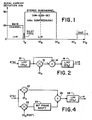
- Fig. 1 illustrates a portion of the BTSC stereo signal having an L+R component; a double sideband, suppressed carrier L-R component; and a pilot signal.
- the respective signal deviations are 25, 50 and 5 kHz.
- the second program channel (SAP) and the professional channel are omitted as not involved in the present invention. As is apparent from this frequency domain view any filtering to separate L+R from L-R is extremely difficult and would require a very precise, and hence very complex and expensive, filter.
- the BTSC stereo signal is input to a first low pass filter (LPF) 10 which has a bandwidth sufficient to encompass both the L+R and L-R components.
- LPF low pass filter
- the filtered output from the LPF 10 is input to a mixer 12 and a summer 14.
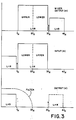
- the second input to the mixer 12 is a frequency 4f H which is four times the pilot frequency f H . Since the L-R component is symmetrical about the suppressed carrier frequency 2f H , i.e., the lower band is the mirror image of the upper band, as illustrated in Fig. 3 the difference frequencies shift the L+R component above the L-R component while leaving the L-R component essentially unchanged.
- the sum and difference outputs from the mixer 12 are input to the summer 14, the difference outputs being the only significant outputs.
- the summer 14 subtracts the output 3(a) from the mixer 12 from the input 3(b) to the mixer to produce an output 3(c) which contains only the original L+R component and a frequency shifted L+R component.
- the output from the summer 14 is input to a second low pass filter 16 to recover the original L+R component.
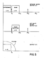
- the L-R component may be recovered as shown in Fig. 4.
- the BTSC stereo signal is input to two mixers 20 and 22.
- the second input to the mixers 20 and 22 is the subcarrier frequency 2f H in phase quadrature, i.e., identical frequencies shifted 90 degrees from each other.
- the output 5(a) of the inphase mixer 20 within the portion of the frequency domain of interest results in the L-R component being shifted down to below the pilot frequency and the L+R component being shifted above the pilot frequency.
- the output 5(b) of the phase shifted mixer 22 has only the L+R component shifted above the pilot frequency, the L-R component having been cancelled due to the phase shift and the symmetry of the upper and lower bands.
- the output of the phase shifted mixer 22 is passed through a 90 degree phase shifter 24 so that the L+R component is either in phase or 180 degrees out of phase with the L+R component from the inphase mixer 20.
- the resulting outputs from the mixers 20 and 22 are input to a summer 26, which either adds or subtracts the two signals depending upon the direction of the 90 degree phase shift by the phase shifter 24.
- the resulting output 5(c) contains only the L-R component which can easily be obtained at this point by a low pass filter 28.
- the present invention provides a circuit for separating the L+R and L-R components of a BTSC stereo signal by mixing the BTSC signal with a multiple of the pilot signal and then summing the results, requiring only simple low pass filters in the circuit.
Abstract
Description
- The present invention relates to signal separation circuits, and more particularly to a circuit for separating the L+R and L-R components of stereo audio in the BTSC system.
- The BTSC system defines a main audio L+R channel up to 15 kHz, a pilot signal at the horizontal sweep frequency of 15.734 kHz, and a double side band, suppressed carrier stereo subchannel symmetrically about a frequence which is twice the pilot signal frequency. To design lowpass filters for this system requires a filter performance several orders of magnitude beyond performance adequate for an FM stereo system. The guardbands between the main channel, the pilot signal and the subchannel are much narrower, and a dbx noise reduction compressor is placed in the subchannel, increasing the potential for subchannel to main channel crosstalk. The guardbands between the main channel and the pilot signal and between the pilot signal and the subchannel are only 734 Hz each, with the separation between the main channel and the subchannel being 1.468 kHZ. Thus, a significant factor in channel separation is the subchannel to main channel crosstalk.
- Subchannel to main channel crosstalk occurs when the lower sideband of the subchannel leaks into the main channel due to inadequate lowpass filtering of the subchannel audio. This crosstalk is nonlinear, i.e., it is highly offensive to the ear because it is not harmonically related to the main channel signals. Additionally when the signal levels are low but the program material contains substantial L-R content, the dbx noise reduction compressor can cause subchannel levels to be 20-30 dB higher than main channel levels. When this occurs the main channel has negligible ability to psychoacoustically mask the crosstalk. Further the greatest gain is likely to be produced at high frequencies -- the very frequencies that appear at the edge of the lower sideband and which are most likely to cause audible crosstalk.
- High performance filters which are adequate for the BTSC system are quite complex, one such having as many as 29 poles of filtering overall, are expensive and require a great stability. If the filter is too abrupt at cutoff, the result is ringing coming out of the filter.
- What is desired is a stable, simple circuit for separating the L+R and L-R components of the BTSC signal while still eliminating crosstalk between the main channel and the subchannel.
- Accordingly the present invention provides a circuit for separating L+R and L-R components of a BTSC signal by mixing the components with a given multiple of the pilot signal frequency and then adding or subtracting the resultant signals. To recover the L+R component the BTSC signal is low pass filtered to obtain both components (L+R and L-R), the components are mixed with a signal four times the pilot signal frequency, and then subtracted from the unmixed, low pass filtered BTSC signal. To obtain the L-R component the BTSC signal is mixed with an unshifted subcarrier frequency and with a 90 degree phase shifted subcarrier frequency, the output of the shifted mixer being shifted an additional 90 degrees, and the outputs of the mixers then being either added or subtracted depending upon the direction of the additional phase shift.
- The objects, advantages and other novel features of the present invention will be apparent from the following detailed description when read in conjunction with the appended claims and attached drawing.
-
- Fig. 1 is a frequency domain view of a portion of the BTSC stereo signal.
- Fig. 2 is a block diagram view of a circuit for obtaining the L+R component of the BTSC stereo signal according to the present invention.
- Fig. 3 is a frequency domain view illustrating the operation of the circuit of Fig. 2.
- Fig. 4 is a block diagram view of a circuit for obtaining the L-R component of the BTSC stereo signal according to the present invention.
- Fig. 5 is a frequency domain view illustrating the operation of the circuit of Fig. 4.
- Fig. 1 illustrates a portion of the BTSC stereo signal having an L+R component; a double sideband, suppressed carrier L-R component; and a pilot signal. The respective signal deviations are 25, 50 and 5 kHz. The second program channel (SAP) and the professional channel are omitted as not involved in the present invention. As is apparent from this frequency domain view any filtering to separate L+R from L-R is extremely difficult and would require a very precise, and hence very complex and expensive, filter.
- Referring now to Fig. 2 the BTSC stereo signal is input to a first low pass filter (LPF) 10 which has a bandwidth sufficient to encompass both the L+R and L-R components. The filtered output from the
LPF 10 is input to amixer 12 and asummer 14. The second input to themixer 12 is a frequency 4fH which is four times the pilot frequency fH. Since the L-R component is symmetrical about the suppressed carrier frequency 2fH, i.e., the lower band is the mirror image of the upper band, as illustrated in Fig. 3 the difference frequencies shift the L+R component above the L-R component while leaving the L-R component essentially unchanged. The sum and difference outputs from themixer 12 are input to thesummer 14, the difference outputs being the only significant outputs. Thesummer 14 subtracts the output 3(a) from themixer 12 from the input 3(b) to the mixer to produce an output 3(c) which contains only the original L+R component and a frequency shifted L+R component. The output from thesummer 14 is input to a secondlow pass filter 16 to recover the original L+R component. - Alternatively the L-R component may be recovered as shown in Fig. 4. The BTSC stereo signal is input to two
mixers mixers inphase mixer 20 within the portion of the frequency domain of interest results in the L-R component being shifted down to below the pilot frequency and the L+R component being shifted above the pilot frequency. The output 5(b) of the phase shiftedmixer 22 has only the L+R component shifted above the pilot frequency, the L-R component having been cancelled due to the phase shift and the symmetry of the upper and lower bands. The output of the phase shiftedmixer 22 is passed through a 90degree phase shifter 24 so that the L+R component is either in phase or 180 degrees out of phase with the L+R component from theinphase mixer 20. The resulting outputs from themixers summer 26, which either adds or subtracts the two signals depending upon the direction of the 90 degree phase shift by thephase shifter 24. The resulting output 5(c) contains only the L-R component which can easily be obtained at this point by alow pass filter 28. - Thus the present invention provides a circuit for separating the L+R and L-R components of a BTSC stereo signal by mixing the BTSC signal with a multiple of the pilot signal and then summing the results, requiring only simple low pass filters in the circuit.
Claims (6)
means for mixing an input stereo signal, having a lower frequency first component, an upper frequency double sideband second component and a pilot signal at a frequency between the two components, with a multiple of the pilot signal frequency;
means for summing the output of the mixing means to eliminate one of the components; and
means for filtering the output of the summing means to recover the remaining component.
a first mixer to which is input the input stereo signal and a mixer frequency which is twice the pilot signal frequency; and
a second mixer to which is input the input stereo signal and a phase quadrature mixture frequency, the mixer frequency being shifted ninety degrees to produce the phase quadrature mixer frequency.
Applications Claiming Priority (2)
| Application Number | Priority Date | Filing Date | Title |
|---|---|---|---|
| US06/882,753 US4757538A (en) | 1986-07-07 | 1986-07-07 | Separation of L+R from L-R in BTSC system |
| US882753 | 1986-07-07 |
Publications (3)
| Publication Number | Publication Date |
|---|---|
| EP0252452A2 true EP0252452A2 (en) | 1988-01-13 |
| EP0252452A3 EP0252452A3 (en) | 1990-11-07 |
| EP0252452B1 EP0252452B1 (en) | 1993-11-10 |
Family
ID=25381266
Family Applications (1)
| Application Number | Title | Priority Date | Filing Date |
|---|---|---|---|
| EP87109625A Expired - Lifetime EP0252452B1 (en) | 1986-07-07 | 1987-07-03 | Separation of L+R from L-R in BTSC system |
Country Status (6)
| Country | Link |
|---|---|
| US (1) | US4757538A (en) |
| EP (1) | EP0252452B1 (en) |
| JP (1) | JPH0681109B2 (en) |
| CA (1) | CA1289080C (en) |
| DE (1) | DE3788086T2 (en) |
| DK (1) | DK345787A (en) |
Cited By (2)
| Publication number | Priority date | Publication date | Assignee | Title |
|---|---|---|---|---|
| EP0420026A2 (en) * | 1989-09-26 | 1991-04-03 | Air Products And Chemicals, Inc. | Preparation of urethane prepolymers having low levels of residual diisocyanate |
| GB2369512A (en) * | 2000-10-07 | 2002-05-29 | Motorola Inc | Signal separation of spectrally close frequencies |
Families Citing this family (30)
| Publication number | Priority date | Publication date | Assignee | Title |
|---|---|---|---|---|
| US4893341A (en) * | 1989-08-01 | 1990-01-09 | At&E Corporation | Digital receiver operating at sub-nyquist sampling rate |
| US5054070A (en) * | 1990-03-05 | 1991-10-01 | Qei Corporation | Stereo signal communication system and method |
| US5239585A (en) * | 1991-07-30 | 1993-08-24 | Texas Instruments Incorporated | Devices, systems, and methods for composite signal decoding |
| US6694128B1 (en) | 1998-08-18 | 2004-02-17 | Parkervision, Inc. | Frequency synthesizer using universal frequency translation technology |
| US7515896B1 (en) * | 1998-10-21 | 2009-04-07 | Parkervision, Inc. | Method and system for down-converting an electromagnetic signal, and transforms for same, and aperture relationships |
| US6091940A (en) | 1998-10-21 | 2000-07-18 | Parkervision, Inc. | Method and system for frequency up-conversion |
| US6061551A (en) | 1998-10-21 | 2000-05-09 | Parkervision, Inc. | Method and system for down-converting electromagnetic signals |
| US7039372B1 (en) | 1998-10-21 | 2006-05-02 | Parkervision, Inc. | Method and system for frequency up-conversion with modulation embodiments |
| US6542722B1 (en) | 1998-10-21 | 2003-04-01 | Parkervision, Inc. | Method and system for frequency up-conversion with variety of transmitter configurations |
| US6370371B1 (en) | 1998-10-21 | 2002-04-09 | Parkervision, Inc. | Applications of universal frequency translation |
| US6049706A (en) | 1998-10-21 | 2000-04-11 | Parkervision, Inc. | Integrated frequency translation and selectivity |
| US6061555A (en) | 1998-10-21 | 2000-05-09 | Parkervision, Inc. | Method and system for ensuring reception of a communications signal |
| US6560301B1 (en) | 1998-10-21 | 2003-05-06 | Parkervision, Inc. | Integrated frequency translation and selectivity with a variety of filter embodiments |
| US7236754B2 (en) | 1999-08-23 | 2007-06-26 | Parkervision, Inc. | Method and system for frequency up-conversion |
| US6813485B2 (en) | 1998-10-21 | 2004-11-02 | Parkervision, Inc. | Method and system for down-converting and up-converting an electromagnetic signal, and transforms for same |
| US6757659B1 (en) * | 1998-11-16 | 2004-06-29 | Victor Company Of Japan, Ltd. | Audio signal processing apparatus |
| US6704558B1 (en) | 1999-01-22 | 2004-03-09 | Parkervision, Inc. | Image-reject down-converter and embodiments thereof, such as the family radio service |
| US6704549B1 (en) | 1999-03-03 | 2004-03-09 | Parkvision, Inc. | Multi-mode, multi-band communication system |
| US6879817B1 (en) | 1999-04-16 | 2005-04-12 | Parkervision, Inc. | DC offset, re-radiation, and I/Q solutions using universal frequency translation technology |
| US6853690B1 (en) | 1999-04-16 | 2005-02-08 | Parkervision, Inc. | Method, system and apparatus for balanced frequency up-conversion of a baseband signal and 4-phase receiver and transceiver embodiments |
| US7693230B2 (en) | 1999-04-16 | 2010-04-06 | Parkervision, Inc. | Apparatus and method of differential IQ frequency up-conversion |
| US7065162B1 (en) | 1999-04-16 | 2006-06-20 | Parkervision, Inc. | Method and system for down-converting an electromagnetic signal, and transforms for same |
| US7110444B1 (en) | 1999-08-04 | 2006-09-19 | Parkervision, Inc. | Wireless local area network (WLAN) using universal frequency translation technology including multi-phase embodiments and circuit implementations |
| US8295406B1 (en) | 1999-08-04 | 2012-10-23 | Parkervision, Inc. | Universal platform module for a plurality of communication protocols |
| US7010286B2 (en) | 2000-04-14 | 2006-03-07 | Parkervision, Inc. | Apparatus, system, and method for down-converting and up-converting electromagnetic signals |
| US7454453B2 (en) | 2000-11-14 | 2008-11-18 | Parkervision, Inc. | Methods, systems, and computer program products for parallel correlation and applications thereof |
| US7072427B2 (en) | 2001-11-09 | 2006-07-04 | Parkervision, Inc. | Method and apparatus for reducing DC offsets in a communication system |
| US7379883B2 (en) | 2002-07-18 | 2008-05-27 | Parkervision, Inc. | Networking methods and systems |
| US7460584B2 (en) | 2002-07-18 | 2008-12-02 | Parkervision, Inc. | Networking methods and systems |
| JP2006508571A (en) * | 2002-11-19 | 2006-03-09 | ケーブル エレクトロニクス インコーポレーテッド | Method and system for digital decoding of MTS signal |
Citations (2)
| Publication number | Priority date | Publication date | Assignee | Title |
|---|---|---|---|---|
| US4502148A (en) * | 1981-06-26 | 1985-02-26 | Pioneer Electronic Corporation | FM Stereo demodulator for demodulating stereo signals directly from an FM intermediate frequency signal |
| JPS60128732A (en) * | 1983-12-16 | 1985-07-09 | Nec Corp | Demodulator of stereo composite signal |
Family Cites Families (4)
| Publication number | Priority date | Publication date | Assignee | Title |
|---|---|---|---|---|
| US4282401A (en) * | 1970-12-24 | 1981-08-04 | Sansui Electric Company | System for transmission and reception of discrete four channel stereo |
| US4497063A (en) * | 1981-06-26 | 1985-01-29 | Pioneer Electronic Corporation | FM stereo demodulator |
| JPS5943644A (en) * | 1982-09-04 | 1984-03-10 | Pioneer Electronic Corp | Fm stereo demodulating circuit |
| JPS62219830A (en) * | 1986-03-20 | 1987-09-28 | Sony Corp | Fm stereo demodulation circuit |
-
1986
- 1986-07-07 US US06/882,753 patent/US4757538A/en not_active Expired - Lifetime
-
1987
- 1987-05-29 CA CA000538392A patent/CA1289080C/en not_active Expired - Fee Related
- 1987-06-22 JP JP62155245A patent/JPH0681109B2/en not_active Expired - Lifetime
- 1987-07-03 DE DE3788086T patent/DE3788086T2/en not_active Expired - Fee Related
- 1987-07-03 EP EP87109625A patent/EP0252452B1/en not_active Expired - Lifetime
- 1987-07-06 DK DK345787A patent/DK345787A/en not_active Application Discontinuation
Patent Citations (2)
| Publication number | Priority date | Publication date | Assignee | Title |
|---|---|---|---|---|
| US4502148A (en) * | 1981-06-26 | 1985-02-26 | Pioneer Electronic Corporation | FM Stereo demodulator for demodulating stereo signals directly from an FM intermediate frequency signal |
| JPS60128732A (en) * | 1983-12-16 | 1985-07-09 | Nec Corp | Demodulator of stereo composite signal |
Non-Patent Citations (2)
| Title |
|---|
| PATENT ABSTRACTS OF JAPAN * |
| PATENT ABSTRACTS OF JAPAN vol.9,no. 288 (E-358)(2011), 15 November 1985; & JP-A-60128732 (NIPPON DENKI) 09.07.1985 * |
Cited By (3)
| Publication number | Priority date | Publication date | Assignee | Title |
|---|---|---|---|---|
| EP0420026A2 (en) * | 1989-09-26 | 1991-04-03 | Air Products And Chemicals, Inc. | Preparation of urethane prepolymers having low levels of residual diisocyanate |
| EP0420026B1 (en) * | 1989-09-26 | 1994-03-16 | Air Products And Chemicals, Inc. | Preparation of urethane prepolymers having low levels of residual diisocyanate |
| GB2369512A (en) * | 2000-10-07 | 2002-05-29 | Motorola Inc | Signal separation of spectrally close frequencies |
Also Published As
| Publication number | Publication date |
|---|---|
| DE3788086T2 (en) | 1994-05-19 |
| US4757538A (en) | 1988-07-12 |
| EP0252452A3 (en) | 1990-11-07 |
| EP0252452B1 (en) | 1993-11-10 |
| DK345787A (en) | 1988-01-08 |
| DE3788086D1 (en) | 1993-12-16 |
| CA1289080C (en) | 1991-09-17 |
| JPH0681109B2 (en) | 1994-10-12 |
| DK345787D0 (en) | 1987-07-06 |
| JPS6315600A (en) | 1988-01-22 |
Similar Documents
| Publication | Publication Date | Title |
|---|---|---|
| US4757538A (en) | Separation of L+R from L-R in BTSC system | |
| US4139866A (en) | Stereophonic television sound transmission system | |
| US4048654A (en) | Stereophonic television sound transmission system | |
| EP0134417B1 (en) | Transmission system for tv signals in directional radio links | |
| US4710814A (en) | Television sound receiving circuit for at least one sound channel contained in an RF signal | |
| US5027402A (en) | Blend-on-noise stereo decoder | |
| CA1282167C (en) | Low distortion filters for separating frequency or phase modulated signals from composite signals | |
| DD250223A5 (en) | CIRCUIT ARRANGEMENT FOR A VIDEO SIGNAL PROCESSING DEVICE | |
| CA1114059A (en) | Television system with two fm soundcarriers | |
| JP2524992B2 (en) | Video signal processor | |
| US4716464A (en) | Single channel if for video and audio | |
| JPS5854691B2 (en) | Stereo demodulation method | |
| US4037055A (en) | Stereophonic demodulator apparatus | |
| US4406922A (en) | Stereo broadcast system | |
| US4669119A (en) | FM stereo receiver | |
| US4637044A (en) | Phase selectable circuit for use in a stereo demodulator | |
| JPS5844679Y2 (en) | Stereo pilot signal removal device in AM stereo receiver | |
| JPS5918772Y2 (en) | FM stereo signal demodulation circuit | |
| US3824346A (en) | Fm stereo demodulator | |
| KR850005217A (en) | FM stereo receiver | |
| JPH06224866A (en) | Signal processing circuit for band division due to fm stereo | |
| US3268663A (en) | Demultiplexer for carrier wave (e. g., fm stereo signal) whose amplitude at fixed intervals is information-representative | |
| EP0695087A2 (en) | Circuit for demodulating at intermediate frequency for a video signal processing apparatus | |
| CA1145032A (en) | Receiver for stereophonic television sound transmission | |
| JPS59834Y2 (en) | FM stereo broadcast multiplex demodulation circuit |
Legal Events
| Date | Code | Title | Description |
|---|---|---|---|
| PUAI | Public reference made under article 153(3) epc to a published international application that has entered the european phase |
Free format text: ORIGINAL CODE: 0009012 |
|
| AK | Designated contracting states |
Kind code of ref document: A2 Designated state(s): DE FR GB NL |
|
| PUAL | Search report despatched |
Free format text: ORIGINAL CODE: 0009013 |
|
| AK | Designated contracting states |
Kind code of ref document: A3 Designated state(s): DE FR GB NL |
|
| 17P | Request for examination filed |
Effective date: 19901102 |
|
| 17Q | First examination report despatched |
Effective date: 19920722 |
|
| GRAA | (expected) grant |
Free format text: ORIGINAL CODE: 0009210 |
|
| AK | Designated contracting states |
Kind code of ref document: B1 Designated state(s): DE FR GB NL |
|
| PG25 | Lapsed in a contracting state [announced via postgrant information from national office to epo] |
Ref country code: NL Effective date: 19931110 Ref country code: FR Effective date: 19931110 |
|
| REF | Corresponds to: |
Ref document number: 3788086 Country of ref document: DE Date of ref document: 19931216 |
|
| EN | Fr: translation not filed | ||
| NLV1 | Nl: lapsed or annulled due to failure to fulfill the requirements of art. 29p and 29m of the patents act | ||
| PLBE | No opposition filed within time limit |
Free format text: ORIGINAL CODE: 0009261 |
|
| STAA | Information on the status of an ep patent application or granted ep patent |
Free format text: STATUS: NO OPPOSITION FILED WITHIN TIME LIMIT |
|
| 26N | No opposition filed | ||
| PGFP | Annual fee paid to national office [announced via postgrant information from national office to epo] |
Ref country code: GB Payment date: 19970620 Year of fee payment: 11 |
|
| PGFP | Annual fee paid to national office [announced via postgrant information from national office to epo] |
Ref country code: DE Payment date: 19970623 Year of fee payment: 11 |
|
| PG25 | Lapsed in a contracting state [announced via postgrant information from national office to epo] |
Ref country code: GB Free format text: LAPSE BECAUSE OF NON-PAYMENT OF DUE FEES Effective date: 19980703 |
|
| GBPC | Gb: european patent ceased through non-payment of renewal fee |
Effective date: 19980703 |
|
| PG25 | Lapsed in a contracting state [announced via postgrant information from national office to epo] |
Ref country code: DE Free format text: LAPSE BECAUSE OF NON-PAYMENT OF DUE FEES Effective date: 19990501 |