EP0253608A2 - Video scanning systems - Google Patents
Video scanning systems Download PDFInfo
- Publication number
- EP0253608A2 EP0253608A2 EP87306175A EP87306175A EP0253608A2 EP 0253608 A2 EP0253608 A2 EP 0253608A2 EP 87306175 A EP87306175 A EP 87306175A EP 87306175 A EP87306175 A EP 87306175A EP 0253608 A2 EP0253608 A2 EP 0253608A2
- Authority
- EP
- European Patent Office
- Prior art keywords
- scanning
- order
- signal
- image
- curve
- Prior art date
- Legal status (The legal status is an assumption and is not a legal conclusion. Google has not performed a legal analysis and makes no representation as to the accuracy of the status listed.)
- Granted
Links
Images


Classifications
-
- H—ELECTRICITY
- H04—ELECTRIC COMMUNICATION TECHNIQUE
- H04N—PICTORIAL COMMUNICATION, e.g. TELEVISION
- H04N3/00—Scanning details of television systems; Combination thereof with generation of supply voltages
- H04N3/10—Scanning details of television systems; Combination thereof with generation of supply voltages by means not exclusively optical-mechanical
- H04N3/30—Scanning details of television systems; Combination thereof with generation of supply voltages by means not exclusively optical-mechanical otherwise than with constant velocity or otherwise than in pattern formed by unidirectional, straight, substantially horizontal or vertical lines
Definitions
- This invention relates to video scanning systems for use for example in television.
- Transmission of images by television is conventionally performed by raster scanning in which a signal is formed by scanning the image in a series of parallel lines, either horizontal or vertical.
- the scan starts at the top left hand corner and finishes at the bottom right hand corner, the scan lines being horizontal.
- each line is scanned in the same direction so that the scan must return to the beginning of each line in, ideally, an infinitessimally short time. Such an action is known as the flyback.
- the scanning in conventional imaging and display devices is by way of a continuously moving electronic beam which is deflected by electric or, usually, magnetic fields. With such devices the beam flyback takes a finite time which is, therefore, an "overhead".
- the vertical scanning waveform needed to ensure the equal spacing of the scan lines is another sawtooth, though of much lower frequency. This has a corresponding flyback, imposing a further "overhead". It should be'noted that the continuous nature of the vertical scan imposes a continuous vertical displacement on the scan lines so that they are not strictly horizontal. However, the skew thus imposed is negligible.
- a disadvantage of raster-based scanning is that it is committed to a standard in the form of lines in the picture. This means that once an image scanning standard is chosen the display must adopt the same standard, or convert the incoming signal to its own line standard, which is a complex and costly process. Moreover, any curtailment in the bandwidth of an analogue channel used to carry the signal will affect only the horizontal resolution of the image, not the vertical resolution. Excessive curtailment will therefore give an unacceptable image quality, inferior to that which could be obtained with equal horizontal and vertical resolutions.
- the invention is applicable to both analogue and digital scans.
- the image is scanned along a trace formed by a defined co-ordinate sequence
- the pixels of the image are scanned in that co-ordinate sequence.
- Fractals may be described as structures whose length is undefinable or infinite as the finer the scale used to observe the structure, the greater the apparent length.
- An example of such a structure is a coastline. The closer it is observed, the greater its length becomes as finer detail becomes resolved.
- Such self-similar shapes are neither one-nor two-dimensional shapes as they are defined by conventional Euclidian geometry. That is, they have a fractional dimension.
- Fractals may be identical on each level or scale, or may be irregular.
- a coastline is an irregular fractal.
- Figure 4 shows how a regular fractal may be generated. This example is the well known Koch curve or Koch snowflake.
- the straight sides of an equilateral triangle Fig. 4b (the initiator shown in Figure 4a) are operated on by a generator shown in Figure 4a. This operation produces the result shown in Figure 4c.
- the operator is then applied to each of the sides of the shape of Figure 4c and then subsequently to the sides of the resultant figure, and so on.
- the result is a figure resembling a snowflake.
- the fractal dimension can be defined as
- the invention will be disclosed in terms of a particular fractal -EI Peano curve, named after the Italian mathematician Guiseppe Peano, see “Selected works of Guiseppe Peano” translated and edited by Hubert C. Kennedy, ISBN 0-04-164002-0, Allen and Unwin. It is also called Hilbert curve.
- the curve may be multi-dimensional; only the two dimensional form is discussed in detail here.
- the Peano scan has three important properties relevant to scanned images:-
- the first property arises because the signal obtained by scanning has information in the horizontal and vertical directions in alternating or near alternating fashion. As a result, if the bandwidth of the signal is limited by a bearer channel the resolution of the image is limited equally in both directions. This is the optimum way of using the available bandwidth.
- the second property arises because each order is derived from the previous one and so creates compatibility. Taking a running average of four coordinate values and then selecting every fourth average produces the coordinate values of the previous order.
- the third property is relevant only to continuous scanning devices such as those using electron beams.
- the curves in Figures 5 to 8 are idealised in the sense that, if the continuously moving scanning spot traces the curve at a constant speed, the x and y coordinate waveforms would be band-limited which would, in general, smooth the corners of the scan.
- Figure 9 shows the effect of limiting the bandwith of the waveforms using a particular filter characteristic which cuts at half the pixel frequency, that is the frequency at which x,y point co-ordinates are generated. This operation would be carried out by the filters following the digital-to-analogue converters generating the waveforms from the coordinate sequences.
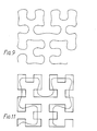
- Figure 11 shows the result of smoothing the scan by taking a running average of four coordinate values and filtering with the first filter.
- the scan closely resembles that of the previous order except for slight overshoots.
- Figures 12 and 13 show the intermediate situations of two-and three-fold averaging and these clearly show how the scan gradually changes from one order to the next.
- the two-fold averager appears to join half the number of points, corresponding to a step of half an order.
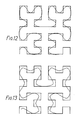
- a 16-fold averaging is necessary, shown in Figure 14. This again closely resembles the ideal curve.
- an eight-fold averager appears like the two-fold averager of Figure 12 but one order lower.
- Averaging by any amount in between corresponds to a curve with intermediate detail.
- averaging is a form of low-pass filtering this means that gradually reducing the bandwidth of the coordinate functions causes the curve to gradually change from one order to the next, always retaining its fractal nature.
- the first case is straightforward in that there are as many independent video samples as there are points in the scan so that each point contributes maximally to the resolution.
- the video signal is not changing as fast as it can from point to point and so the resolution is limited by the signal.
- the source scan is assumed to be of a higer order than the display. In this case the display will average out of the signal by superposition, either exactly, if discrete, or approximately, if continuous. This can be appreciated by considering adjacent orders of scan.
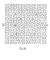
- Figure 15 shows the superposition of third and fourth-order scans. As can be seen, the higher order scan is never more than half a pixel displaced from the lower order. Thus, four adjacent samples of a signal derived on the higher order, if displayed by a continuous scan on the lower order, will suffer no more than half a pixel displacement and so will tend to superpose.
- the system is particularly suitable for use with imaging and display devices which are based on discrete rather than continuous scanning. These include systems comprising cameras based on charge- coupled devices (CCDs) for example. Addressable display devices would be particularly suitable.
- CCDs charge- coupled devices
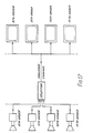
- FIG. 17 An outline block diagram of a television system embodying the invention is shown in Figure 17. Synchronised cameras operating with various orders of scan may be selected at will and their signals transmitted through the channel.
- the ninth-order scan camera represents, approximately, the current system.
- the eighth order scan camera represents, say, a low-resolution lightweight 'electronic journalism' camera whilst the 10th-order scan camera represents a high definition camera. They could be used in different programmes or even in the same programme.
- the llth-order scan camera represents a camera which could be developed in the future, being introduced when required.
- the same remarks apply to the hierarchy of displays, the eighth-order display representing, say, a wrist-watch receiver based on a liquid crystal display.
- the system is capable of being introduced piecemeal and so thus coexisting with current scanning technology. If it were introduced on the channel then compatibility with current technology would require raster-to-Peano converters in conventional cameras and Peano-to-Raster converters in conventional displays, as shown in Figure 18, the converters merely re-ordering the sequence of incoming pixel values. Such converters would consist simply of a picture store which would write the pixel data in one sequence and read it in another. This re-ordering of data could also be regarded as a scrambling technique to prevent unauthorised reception of a newly-introduced service.
- the scan could be generated using a memory addressed by a counter as shown in Figure 19.
- An nth order scan would require a memory of 2 2n locations, each of 2n bits, containing n-bit x and y values and a 2n-bit memory counter able to count from 0 to 2 2 " -1.
- the contents of the memory could be derived according to the method described in the appendix below.
- the two outputs of the memory can be used directly to address a discrete scanning device. However, for a continuous scanning device the memory outputs need to be fed to two n-bit digital-to-analogue converters to produce continous wave forms.
- the x and y coordinate sequences for the first order case of Figure 6 are shown in Table 1, in units of the scan step.
- the y sequence is a palindrome and the x sequence is a complementary palindrome.
- the coordinate sequences of the second-order case, written in binary form, are shown in Table 2.
- each coordinate requires 2 bits and there are 16 entries.
- the more significant bit is seen to be a replication of the corresponding first-order pattern, each entry being replicated four times.
- the less significant bit is seen to be the sequence YXX7 for the x coordinate or XYYX for the y coordinate where X and Y are the first-order patterns of the x and y coordinates.
- the first of these sequences is a complementary palindrome and the second is a palindrome.
- the third-order case shown in Table 3, has 64 entries of three bit values, the sequences of the first two bits of x and y being the same as those of the corresponding second-order case, each entry being replicated four times.
- the least significant bit of the x coordinate has the sequence XYYX YXX Y YXX Y XYY X where X and Y represent the same sequences as before. It can be seen that the initial sequence of each group of four follows the same pattern as the sequences in the first group.
- the least significant bit of the y coordinate has the sequence YXXY XYYX XYYX Y. It will be noted that the least significant bits are appropriately palindromic or complementary palindromic.
Abstract
Description
- This invention relates to video scanning systems for use for example in television.
- Transmission of images by television is conventionally performed by raster scanning in which a signal is formed by scanning the image in a series of parallel lines, either horizontal or vertical. In broadcast television the scan starts at the top left hand corner and finishes at the bottom right hand corner, the scan lines being horizontal. Moreover, each line is scanned in the same direction so that the scan must return to the beginning of each line in, ideally, an infinitessimally short time. Such an action is known as the flyback.
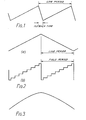
- The scanning in conventional imaging and display devices is by way of a continuously moving electronic beam which is deflected by electric or, usually, magnetic fields. With such devices the beam flyback takes a finite time which is, therefore, an "overhead". The horizontal scanning waveform, which is proportional to the deflecting field, therefore appears as in Figure 1, the idealised version of which is known as a sawtooth waveform.
- Similarly, the vertical scanning waveform needed to ensure the equal spacing of the scan lines is another sawtooth, though of much lower frequency. This has a corresponding flyback, imposing a further "overhead". It should be'noted that the continuous nature of the vertical scan imposes a continuous vertical displacement on the scan lines so that they are not strictly horizontal. However, the skew thus imposed is negligible.
- The large rate of change of the flyback in the horizontal scan waveform is used to provide the high voltage needed in a conventional CRT display. However, it can cause problems if the line rate is increased to provide scanning for higher definition formats since the flyback time of conventional deflection circuits may become a significant proportion of the line period. For this reason, UK Patent Application 2,137,844A has proposed a boustrophedonic scanning format in which lines are alternately scanned in opposite directions. This requires a triangular form for the horizontal scan waveform as shown in Figure 2 (a). This eliminates the flyback, but the sawtooth of the vertical scan must now be modified to a stepped form as shown in Figure 2 (b) to ensure that adjacent lines are parallel. It also requires that non-linearities in the horizontal scan waveform result in a symmetrical function as shown in Figure 3.
- A disadvantage of raster-based scanning is that it is committed to a standard in the form of lines in the picture. This means that once an image scanning standard is chosen the display must adopt the same standard, or convert the incoming signal to its own line standard, which is a complex and costly process. Moreover, any curtailment in the bandwidth of an analogue channel used to carry the signal will affect only the horizontal resolution of the image, not the vertical resolution. Excessive curtailment will therefore give an unacceptable image quality, inferior to that which could be obtained with equal horizontal and vertical resolutions.
- The present invention is defined by the appended claims to which reference should now be made.
- The invention is applicable to both analogue and digital scans. In the former case the image is scanned along a trace formed by a defined co-ordinate sequence, and in the latter case the pixels of the image are scanned in that co-ordinate sequence.
- We have appreciated that it would be possible to have a scanning format which is not committed to a line standard and therefore is open to evolution, i.e., the image scanning may be upgraded in acuity without needing a change in the structure of the display. This means that it is downwards compatible. Moreover, it is possible for such a format to be upwards compatible such that the display can be upgraded without changing the source scanning format. Such a technique relies on the use of FRACTALS for defining the scanning locus.
- Fractals may be described as structures whose length is undefinable or infinite as the finer the scale used to observe the structure, the greater the apparent length. An example of such a structure is a coastline. The closer it is observed, the greater its length becomes as finer detail becomes resolved.
- Such self-similar shapes are neither one-nor two-dimensional shapes as they are defined by conventional Euclidian geometry. That is, they have a fractional dimension.
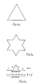
- Fractals may be identical on each level or scale, or may be irregular. A coastline is an irregular fractal. Figure 4 shows how a regular fractal may be generated. This example is the well known Koch curve or Koch snowflake. The straight sides of an equilateral triangle Fig. 4b (the initiator shown in Figure 4a) are operated on by a generator shown in Figure 4a. This operation produces the result shown in Figure 4c. The operator is then applied to each of the sides of the shape of Figure 4c and then subsequently to the sides of the resultant figure, and so on. The result is a figure resembling a snowflake.
- It can be shown that the fractal dimension can be defined as
- D = - log (N)/Iog ( ; )
- where N is the number of parts of the objected generated and is the similarity ratio which is used to divide the initiator. For the Koch curve of Figure 4; N = 4 and + =
- so that D = 1.26
- A fuller description of fractals can be found in the book: Mandlebrot FRACTALS - Form, Chance and Dimension, W.H. Freeman, ISBN 0-7167-0473-0. The use of fractals in the field of computer graphics to simulate texture is well established. The use of a fractal curve to explore a multi-dimensional space is known from Stevens, R.J., Lehar, A.F. and Preston, F.H. 1982, "Data ordering and compression of multispectral images using the Peano scan", International Conference on electronic image processing 26-28 July 1982, IEE conference publication No. 214 pages 209-213. However, the use of a fractal curve to scan an image for transmission and display, with its attendant advantages is thought to be novel.
- The invention will be disclosed in terms of a particular fractal -EI Peano curve, named after the Italian mathematician Guiseppe Peano, see "Selected works of Guiseppe Peano" translated and edited by Hubert C. Kennedy, ISBN 0-04-164002-0, Allen and Unwin. It is also called Hilbert curve. However, other forms of fractal may be more suitable, in particular the Sierpinski curve, described by Writh, N. in "Algorithms + data structures = programs", Prentice-Hall Inc., ISBN 0-13-022418-9 pages 134-137. In general, the curve may be multi-dimensional; only the two dimensional form is discussed in detail here.
- The invention will be described by way of example with reference to the drawings, in which:-
- Figure 1 (referred to above) illustrates the sawtooth waveform of conventional raster scanning;
- Figure 2 (referred to above) shows the waveforms required for boustrophedonic scanning in (a) the horizontal (b) the vertical directions;
- Figure 3 (referred to above) illustrates the permissible non-linearity of the horizontal scan in boustrophedonic scanning;
- Figure 4 (referred to above) illustrates the steps in generating a Koch curve;
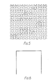
- Figure 5 illustrates a fifth-order (32 x 32) Peano curve;
- Figure 6 illustrates a first-order (basic) Peano curve;
- Figure 7 illustrates a second-order Peano curve;
- Figure 8 illustrates a third-order Peano curve;
- Figure 9 shows the smoothed third-order curve resulting from band-limiting the coordinate waveforms fairly sharply to half the pixel frequency;
- Figure 10 illustrates a portion of the horizontal and vertical waveforms interpolated by a raised cosine filter;
- Figure 11 illustrates the effect of four-fold averaging and interpolation (filtering) of the scan;
- Figure 12 illustrates the effect of two-fold averaging of the scan;
- Figure 13 illustrates the effect of three-fold averaging of the scan;
- Figure 14 illustrates the effect of 16-fold averaging of the scan;
- Figure 15 illustrates the superposition of the third and fourth-order scans;
- Figure 16 shows the starting and finishing points for various aspect ratios: (a) 2:1 (b) 3:1 (c) 4:1 (d) 3:2 (e) 4:3;
- Figure 17 is a block diagram of a television system embodying the invention;
- Figure 18 is a block diagram illustrating conversion for compatibility with the current technology; and
- Figure 19 is a block diagram of a basic circuit for generating an n-th order scan.
- Figure 5 shows a two-dimensional fifth-order Peano curve, i.e., a curve connecting an array of 32 x 32 points. Close inspection shows that it can be divided into quarters, each of which is connected by a single step. The quarters, in turn, can be further subdivided into quarters, again connected by only a single step, and so on. Further, the quarters are seen to be replicas, either directly or rotated through a right angle.
- Figures 6, 7 and 8 show the first, second and third order curves respectively. It can be seen that each order is derived from the previous order according to simple geometrical rules. Alternatively, the derivation of each order can be considered by way of the Cartesian coordinate sequences as shown in the Appendix below. These sequences, when interpolated, are the waveforms that would need to be applied to the horizontal and vertical deflection circuits of a conventional camera tube or CRT display. Alternatively, they are the horizontal and vertical addressing sequences that would be needed for a discrete display device. The derivation process can be repeated indefinitely to yield higher and higher order curves connecting more and more points.
- The Peano scan has three important properties relevant to scanned images:-
- 1. It gives a means of simultaneously altering the horizontal and vertical resolution of the image.
- 2. The set of curves for different orders form a hierarchical family capable of resolving finer and finer detail.
- 3. The curve for a particular order 'gracefully degrades' to the previous order when smoothed.
- The first property arises because the signal obtained by scanning has information in the horizontal and vertical directions in alternating or near alternating fashion. As a result, if the bandwidth of the signal is limited by a bearer channel the resolution of the image is limited equally in both directions. This is the optimum way of using the available bandwidth.
- The second property arises because each order is derived from the previous one and so creates compatibility. Taking a running average of four coordinate values and then selecting every fourth average produces the coordinate values of the previous order.
- The third property is relevant only to continuous scanning devices such as those using electron beams. The curves in Figures 5 to 8 are idealised in the sense that, if the continuously moving scanning spot traces the curve at a constant speed, the x and y coordinate waveforms would be band-limited which would, in general, smooth the corners of the scan. Figure 9 shows the effect of limiting the bandwith of the waveforms using a particular filter characteristic which cuts at half the pixel frequency, that is the frequency at which x,y point co-ordinates are generated. This operation would be carried out by the filters following the digital-to-analogue converters generating the waveforms from the coordinate sequences.
- There is, however one special case where limiting the bandwidth of the waveforms does not smooth the curve. This is the case of a simple raised-cosine filter pulse response, the base width of the pulse being the pixel spacing. Figure 10 shows a portion of the waveforms when so filtered. As can be seen, at the ideal point values, each coordinate has zero rate of change and neither overshoots. This means that the spot comes momentarily to rest and, as only one coordinate changes at any time, the motion passes smoothly from one coordinate to the other.
- Figure 11 shows the result of smoothing the scan by taking a running average of four coordinate values and filtering with the first filter. As can be seen, the scan closely resembles that of the previous order except for slight overshoots. Figures 12 and 13 show the intermediate situations of two-and three-fold averaging and these clearly show how the scan gradually changes from one order to the next. The two-fold averager appears to join half the number of points, corresponding to a step of half an order. To obtain the next lowest order, appearing to join one sixteenth of the number of points, a 16-fold averaging is necessary, shown in Figure 14. This again closely resembles the ideal curve. Likewise, an eight-fold averager appears like the two-fold averager of Figure 12 but one order lower. Averaging by any amount in between corresponds to a curve with intermediate detail. As averaging is a form of low-pass filtering this means that gradually reducing the bandwidth of the coordinate functions causes the curve to gradually change from one order to the next, always retaining its fractal nature.
- Given that either the video signal or the scan waveforms may be band-limited to an arbitrary degree, three cases arise at the display. These are:
- 1. The video and scan bandwidths are equal.
- 2. The video bandwidth is less than the scan bandwidth.
- 3. The video bandwidth is greater than the scan bandwidth.
- The first case is straightforward in that there are as many independent video samples as there are points in the scan so that each point contributes maximally to the resolution. In the second case the video signal is not changing as fast as it can from point to point and so the resolution is limited by the signal. In the third case the source scan is assumed to be of a higer order than the display. In this case the display will average out of the signal by superposition, either exactly, if discrete, or approximately, if continuous. This can be appreciated by considering adjacent orders of scan. Figure 15 shows the superposition of third and fourth-order scans. As can be seen, the higher order scan is never more than half a pixel displaced from the lower order. Thus, four adjacent samples of a signal derived on the higher order, if displayed by a continuous scan on the lower order, will suffer no more than half a pixel displacement and so will tend to superpose.
- This compatibility between different situations carries the important implication that it is not necessary to know the order of the scan in order to reproduce a version of the image. Thus we have an image transmission system which is independent of the number of pixels in the image. Only the number of fields per second, the form of the fractal (i.e., that it is a Peano curve) and the starting and finishing points need to be standardised.
- Thus we have a hierarchical family of scanning standards for transmitting and displaying images such that an image scanned by one member of the family may be displayed by another member of the family without knowledge of the first member. Such an arrangement allows an evolution of scanning acuity to occur.
- An apparent theoretical objection to the idea is that it can be applied only to square arrays of points. Arbitrary image aspect ratios are not possible. However, ratios of 2:1 3:1 4:1 3:2 and 4:3 are possible by starting and finishing at the points shown in Figure 16. Small deviations from these values are possible by altering the pixel. aspect ratio without departing significantly from the spirit of isotropic resolution.
- Because the scan is contiguous there is no flyback except between fields and thus time is saved. Even field flybacks may be eliminated by using a modified square scan consisting of two 2:1 scans joined at their endpoints. Alternatively, a Sierpinski curve may be used which has an inherently endless form. In such a case, synchronising information would have to be sparse, compared with the present systems, possibly consisting of a recognisable framing pattern.
- The system is particularly suitable for use with imaging and display devices which are based on discrete rather than continuous scanning. These include systems comprising cameras based on charge- coupled devices (CCDs) for example. Addressable display devices would be particularly suitable.
- An outline block diagram of a television system embodying the invention is shown in Figure 17. Synchronised cameras operating with various orders of scan may be selected at will and their signals transmitted through the channel. The ninth-order scan camera represents, approximately, the current system. The eighth order scan camera represents, say, a low-resolution lightweight 'electronic journalism' camera whilst the 10th-order scan camera represents a high definition camera. They could be used in different programmes or even in the same programme. The llth-order scan camera represents a camera which could be developed in the future, being introduced when required. The same remarks apply to the hierarchy of displays, the eighth-order display representing, say, a wrist-watch receiver based on a liquid crystal display.
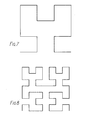
- The system is capable of being introduced piecemeal and so thus coexisting with current scanning technology. If it were introduced on the channel then compatibility with current technology would require raster-to-Peano converters in conventional cameras and Peano-to-Raster converters in conventional displays, as shown in Figure 18, the converters merely re-ordering the sequence of incoming pixel values. Such converters would consist simply of a picture store which would write the pixel data in one sequence and read it in another. This re-ordering of data could also be regarded as a scrambling technique to prevent unauthorised reception of a newly-introduced service.
- The scan could be generated using a memory addressed by a counter as shown in Figure 19. An nth order scan would require a memory of 22nlocations, each of 2n bits, containing n-bit x and y values and a 2n-bit memory counter able to count from 0 to 22 " -1. The contents of the memory could be derived according to the method described in the appendix below. The two outputs of the memory can be used directly to address a discrete scanning device. However, for a continuous scanning device the memory outputs need to be fed to two n-bit digital-to-analogue converters to produce continous wave forms.
- The x and y coordinate sequences for the first order case of Figure 6 are shown in Table 1, in units of the scan step. The y sequence is a palindrome and the x sequence is a complementary palindrome. The coordinate sequences of the second-order case, written in binary form, are shown in Table 2. As there are 4 x 4 points, each coordinate requires 2 bits and there are 16 entries. The more significant bit is seen to be a replication of the corresponding first-order pattern, each entry being replicated four times. The less significant bit is seen to be the sequence YXX7 for the x coordinate or XYYX for the y coordinate where X and Y are the first-order patterns of the x and y coordinates. The first of these sequences is a complementary palindrome and the second is a palindrome.

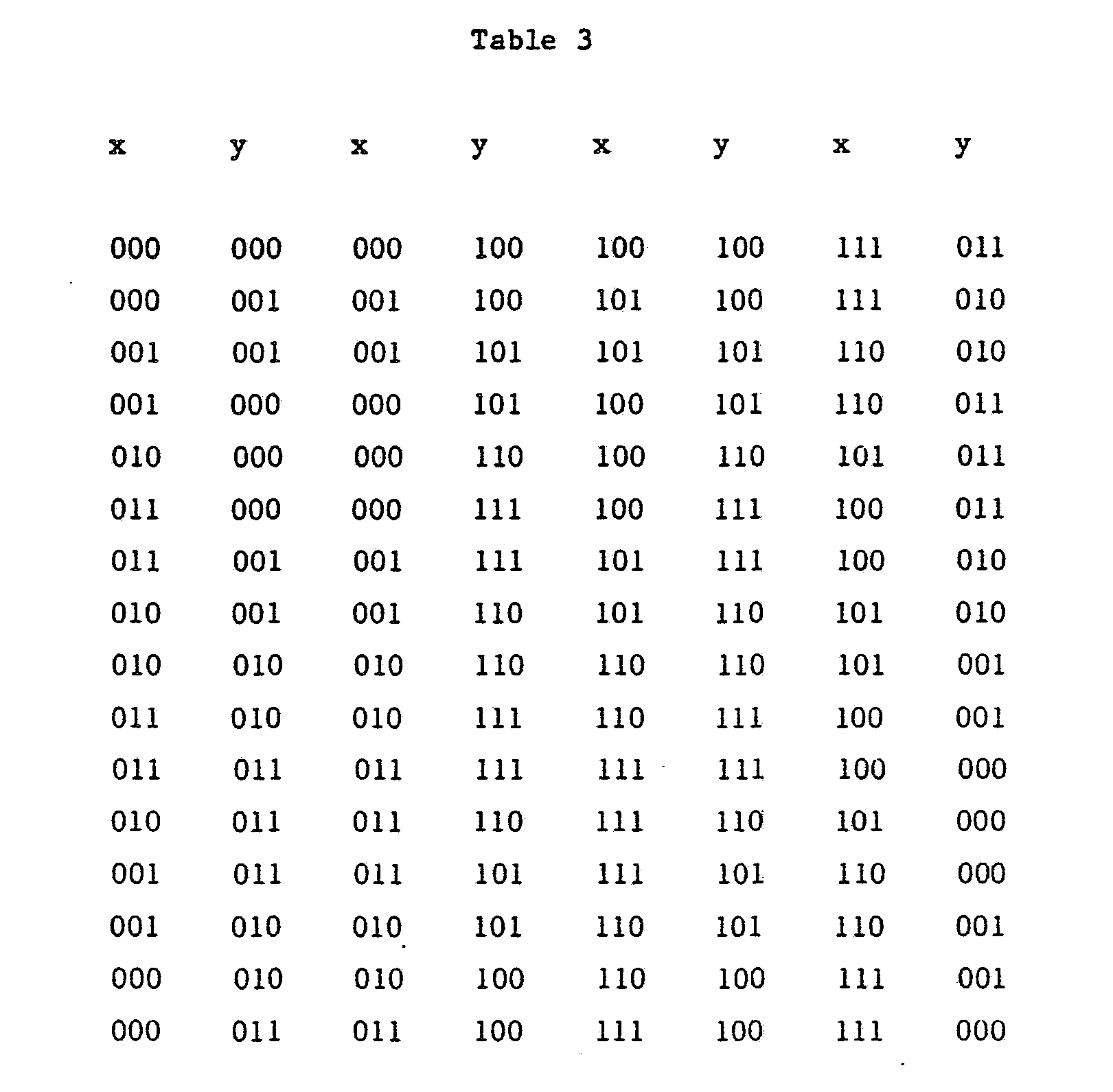
- Development of the higher order cases proceeds along the same rules. The third-order case, shown in Table 3, has 64 entries of three bit values, the sequences of the first two bits of x and y being the same as those of the corresponding second-order case, each entry being replicated four times. The least significant bit of the x coordinate has the sequence XYYX YXX
Y YXX YXYY X where X and Y represent the same sequences as before. It can be seen that the initial sequence of each group of four follows the same pattern as the sequences in the first group. Likewise, the least significant bit of the y coordinate has the sequence YXXY XYYX XYYXYXX Y. It will be noted that the least significant bits are appropriately palindromic or complementary palindromic. - The rule for derivation of the higher order cases is therefore.
- 1. The sequences of all but the least significant bit are those of the previous order, each entry being replicated four times.
- 2. The sequence of the least significant bit consists of groups of four sub-sequences, each taking the form ABB A .
- 3. The first sub-sequence of the nth group of four is the same as the nth sub-sequence.
- 4. A can be X or Y or X or Y. If A is X then B is Y and vice versa.
- 5. The first sub-sequence of x is X if the order is odd and Y if it is even, and vice versa for y.
- 6. X and Y are the x and y sequences of the first order case.
Claims (15)
Applications Claiming Priority (2)
| Application Number | Priority Date | Filing Date | Title |
|---|---|---|---|
| GB8617076 | 1986-07-14 | ||
| GB868617076A GB8617076D0 (en) | 1986-07-14 | 1986-07-14 | Video scanning systems |
Publications (3)
| Publication Number | Publication Date |
|---|---|
| EP0253608A2 true EP0253608A2 (en) | 1988-01-20 |
| EP0253608A3 EP0253608A3 (en) | 1989-05-31 |
| EP0253608B1 EP0253608B1 (en) | 1993-01-13 |
Family
ID=10601007
Family Applications (1)
| Application Number | Title | Priority Date | Filing Date |
|---|---|---|---|
| EP87306175A Expired - Lifetime EP0253608B1 (en) | 1986-07-14 | 1987-07-13 | Video scanning systems |
Country Status (5)
| Country | Link |
|---|---|
| US (1) | US4843468B1 (en) |
| EP (1) | EP0253608B1 (en) |
| JP (1) | JPS6351774A (en) |
| DE (1) | DE3783525T2 (en) |
| GB (2) | GB8617076D0 (en) |
Cited By (7)
| Publication number | Priority date | Publication date | Assignee | Title |
|---|---|---|---|---|
| DE3831239A1 (en) * | 1988-09-14 | 1990-03-22 | Thomson Brandt Gmbh | DEFLECTION CIRCUIT FOR TELEVISION TUBES |
| WO1991002318A1 (en) * | 1989-08-04 | 1991-02-21 | Aware, Inc. | Signal processing device and method |
| GB2253978A (en) * | 1990-12-15 | 1992-09-23 | Beverley Hugh Pardoe | Raster scan system without flyback |
| WO1993002526A1 (en) * | 1991-07-19 | 1993-02-04 | Laboratoire De Traitement Des Signaux | Method for compressing digital image sequences |
| EP1592083A2 (en) * | 2000-01-19 | 2005-11-02 | Fractus, S.A. | Space-filling miniature antennas |
| EP1699110A2 (en) * | 2000-01-19 | 2006-09-06 | Fractus, S.A. | Space-filling miniature antennas |
| US8738103B2 (en) | 2006-07-18 | 2014-05-27 | Fractus, S.A. | Multiple-body-configuration multimedia and smartphone multifunction wireless devices |
Families Citing this family (46)
| Publication number | Priority date | Publication date | Assignee | Title |
|---|---|---|---|---|
| GB2215935B (en) * | 1988-03-17 | 1992-12-16 | British Broadcasting Corp | The use of interlace in fractal scanning |
| US4982283A (en) * | 1988-05-06 | 1991-01-01 | General Electric Company | Line-sequential pyramid processing of a plurality of raster-scanned image variables |
| FR2657695B1 (en) * | 1990-01-30 | 1992-04-17 | Elf Aquitaine | METHOD FOR POINTING SURFACES IN A 3D VOLUME. |
| US5680172A (en) * | 1992-01-21 | 1997-10-21 | Video Post & Transfer, Inc. | Consecutive frame scanning of cinematographic film |
| US5602943A (en) * | 1992-04-28 | 1997-02-11 | Velho; Luiz C. | Digital halftoning space filling curves |
| US5444491A (en) * | 1993-02-26 | 1995-08-22 | Massachusetts Institute Of Technology | Television system with multiple transmission formats |
| US5453792A (en) * | 1994-03-18 | 1995-09-26 | Prime Image, Inc. | Double video standards converter |
| US5519438A (en) * | 1994-06-30 | 1996-05-21 | Intel Corporation | Computer with a video subsystem that contains timers which are used to create calibration tables correlating time intervals with the decoding and converting of video input signals |
| NL9401150A (en) * | 1994-07-12 | 1996-02-01 | Nederland Ptt | Method for presenting on a receiving side a first number of video signals originating from a transmitting side, as well as a system, as well as a transmitter, as well as a network, and also a receiver. |
| US5771073A (en) * | 1995-06-07 | 1998-06-23 | Massachusetts Institute Of Technology | Advanced television system using a different encoding technique for non-image areas |
| US5737448A (en) * | 1995-06-15 | 1998-04-07 | Intel Corporation | Method and apparatus for low bit rate image compression |
| US5982386A (en) * | 1996-04-02 | 1999-11-09 | Dainippon Screen Mfg. Co., Ltd. | Image boundary correction by fractal processing |
| US6211869B1 (en) * | 1997-04-04 | 2001-04-03 | Avid Technology, Inc. | Simultaneous storage and network transmission of multimedia data with video host that requests stored data according to response time from a server |
| US6141007A (en) * | 1997-04-04 | 2000-10-31 | Avid Technology, Inc. | Newsroom user interface including multiple panel workspaces |
| US6038573A (en) * | 1997-04-04 | 2000-03-14 | Avid Technology, Inc. | News story markup language and system and process for editing and processing documents |
| US5920359A (en) * | 1997-05-19 | 1999-07-06 | International Business Machines Corporation | Video encoding method, system and computer program product for optimizing center of picture quality |
| US6317515B1 (en) | 1998-04-03 | 2001-11-13 | Avid Technology, Inc. | Method and apparatus for encoding and decoding a data stream using inferential techniques |
| US6211889B1 (en) * | 1998-06-30 | 2001-04-03 | Sun Microsystems, Inc. | Method and apparatus for visualizing locality within an address space |
| US6233367B1 (en) * | 1998-09-09 | 2001-05-15 | Intel Corporation | Multi-linearization data structure for image browsing |
| BR9917493B1 (en) | 1999-09-20 | 2012-09-18 | multi-level antenna. | |
| CN1196231C (en) * | 1999-10-26 | 2005-04-06 | 弗拉克托斯股份有限公司 | Interlaced multiband antenna arrays |
| US6473122B1 (en) * | 1999-12-06 | 2002-10-29 | Hemanth G. Kanekal | Method and apparatus to capture high resolution images using low resolution sensors and optical spatial image sampling |
| EP1538699A3 (en) * | 2000-01-19 | 2006-01-04 | Fractus, S.A. | Space-filling miniature antennas |
| ATE378700T1 (en) * | 2000-04-19 | 2007-11-15 | Advanced Automotive Antennas S | ADVANCED MULTI-PLANE ANTENNA FOR MOTOR VEHICLES |
| US7511675B2 (en) * | 2000-10-26 | 2009-03-31 | Advanced Automotive Antennas, S.L. | Antenna system for a motor vehicle |
| WO2002063714A1 (en) | 2001-02-07 | 2002-08-15 | Fractus, S.A. | Miniature broadband ring-like microstrip patch antenna |
| CN1507673A (en) * | 2001-04-16 | 2004-06-23 | �����ɷ� | Dual-band dual-polarized antenna array |
| US7079289B2 (en) * | 2001-10-01 | 2006-07-18 | Xerox Corporation | Rank-order error diffusion image processing |
| DE60132638T2 (en) * | 2001-10-16 | 2009-01-29 | Fractus, S.A. | MULTI FREQUENCY MICROBAND PATCH ANTENNA WITH PARASITIC COUPLED ELEMENTS |
| BR0117154A (en) * | 2001-10-16 | 2004-10-26 | Fractus Sa | Loaded Antenna |
| US9755314B2 (en) | 2001-10-16 | 2017-09-05 | Fractus S.A. | Loaded antenna |
| EP1942551A1 (en) | 2001-10-16 | 2008-07-09 | Fractus, S.A. | Multiband antenna |
| AU1355402A (en) * | 2002-01-25 | 2003-07-31 | James Edward Maguire | Non raster image scanning |
| AU2002340506A1 (en) | 2002-11-07 | 2004-06-07 | Fractus, S.A. | Integrated circuit package including miniature antenna |
| ES2380576T3 (en) * | 2002-12-22 | 2012-05-16 | Fractus, S.A. | Unipolar multiband antenna for a mobile communications device |
| JP2004318466A (en) * | 2003-04-16 | 2004-11-11 | Matsushita Electric Ind Co Ltd | Gift coupon, gift coupon issuing system, and system for using gift coupon |
| EP1709704A2 (en) * | 2004-01-30 | 2006-10-11 | Fractus, S.A. | Multi-band monopole antennas for mobile communications devices |
| EP1771919A1 (en) * | 2004-07-23 | 2007-04-11 | Fractus, S.A. | Antenna in package with reduced electromagnetic interaction with on chip elements |
| EP1810369A1 (en) * | 2004-09-27 | 2007-07-25 | Fractus, S.A. | Tunable antenna |
| EP1810368A1 (en) * | 2004-11-12 | 2007-07-25 | Fractus, S.A. | Antenna structure for a wireless device with a ground plane shaped as a loop |
| EP1880444A1 (en) * | 2005-05-13 | 2008-01-23 | Fractus, S.A. | Antenna diversity system and slot antenna component |
| WO2010015364A2 (en) | 2008-08-04 | 2010-02-11 | Fractus, S.A. | Antennaless wireless device capable of operation in multiple frequency regions |
| EP2319122A2 (en) | 2008-08-04 | 2011-05-11 | Fractus S.A. | Antennaless wireless device |
| WO2011095330A1 (en) | 2010-02-02 | 2011-08-11 | Fractus, S.A. | Antennaless wireless device comprising one or more bodies |
| RU2454761C2 (en) * | 2010-06-29 | 2012-06-27 | Общество с ограниченной ответственностью "АВТОТЕХНОЛОГИИ" | Small universal radio/tv antenna |
| WO2012017013A1 (en) | 2010-08-03 | 2012-02-09 | Fractus, S.A. | Wireless device capable of multiband mimo operation |
Citations (1)
| Publication number | Priority date | Publication date | Assignee | Title |
|---|---|---|---|---|
| JPS62264764A (en) * | 1986-05-12 | 1987-11-17 | Nippon Telegr & Teleph Corp <Ntt> | Picture information compression system |
Family Cites Families (8)
| Publication number | Priority date | Publication date | Assignee | Title |
|---|---|---|---|---|
| US2899495A (en) * | 1959-08-11 | ml output | ||
| GB503555A (en) * | 1937-10-14 | 1939-04-11 | Alan Dower Blumlein | Improvements in or relating to television transmitting and receiving systems |
| US2911463A (en) * | 1957-12-30 | 1959-11-03 | Bell Telephone Labor Inc | High resolution scanning system |
| GB926798A (en) * | 1960-10-26 | 1963-05-22 | Marconi Wireless Telegraph Co | Improvements in or relating to television systems |
| US3309461A (en) * | 1962-08-01 | 1967-03-14 | Battelle Development Corp | Pseudo-random electron beam scanning system for narrow bandwidth image transmission |
| US3342937A (en) * | 1962-08-01 | 1967-09-19 | Battelle Development Corp | Synchronizing of electron beam scanning in a narrow bandwidth pseudorandom dot scan television system |
| US3499980A (en) * | 1967-05-04 | 1970-03-10 | Itt | Sequential dot interlace system and method for television |
| DE2131311C3 (en) * | 1971-06-24 | 1975-09-11 | Licentia Patent-Verwaltungs-Gmbh, 6000 Frankfurt | Image transmission system |
-
1986
- 1986-07-14 GB GB868617076A patent/GB8617076D0/en active Pending
-
1987
- 1987-07-13 DE DE8787306175T patent/DE3783525T2/en not_active Expired - Fee Related
- 1987-07-13 EP EP87306175A patent/EP0253608B1/en not_active Expired - Lifetime
- 1987-07-13 GB GB8716421A patent/GB2193411B/en not_active Expired - Fee Related
- 1987-07-14 US US90/002843A patent/US4843468B1/en not_active Expired - Fee Related
- 1987-07-14 JP JP62175807A patent/JPS6351774A/en active Pending
Patent Citations (1)
| Publication number | Priority date | Publication date | Assignee | Title |
|---|---|---|---|---|
| JPS62264764A (en) * | 1986-05-12 | 1987-11-17 | Nippon Telegr & Teleph Corp <Ntt> | Picture information compression system |
Non-Patent Citations (2)
| Title |
|---|
| PATENT ABSTRACTS OF JAPAN, vol. 12, no. 150 (E-606)[2997], 10th May 1988; & JP-A-62 264 764 (NIPPON TELEGR. & TELEPH. CORP.) 17-11-1987 * |
| PROC. OF THE IEEE, vol. 67, no. 10, October 1979, pages 1465-1466, IEEE, New York, US; J.J. KOENDERINK et al.: "New type of raster scan preserves the topology of the image" * |
Cited By (19)
| Publication number | Priority date | Publication date | Assignee | Title |
|---|---|---|---|---|
| DE3831239A1 (en) * | 1988-09-14 | 1990-03-22 | Thomson Brandt Gmbh | DEFLECTION CIRCUIT FOR TELEVISION TUBES |
| US4988927A (en) * | 1988-09-14 | 1991-01-29 | Deutsche Thomson-Brandt Gmbh | Deflection circuit for a television picture tube |
| WO1991002318A1 (en) * | 1989-08-04 | 1991-02-21 | Aware, Inc. | Signal processing device and method |
| US5073964A (en) * | 1989-08-04 | 1991-12-17 | Aware, Inc. | Signal processing device and method |
| GB2253978A (en) * | 1990-12-15 | 1992-09-23 | Beverley Hugh Pardoe | Raster scan system without flyback |
| GB2253978B (en) * | 1990-12-15 | 1995-04-26 | Beverley Hugh Pardoe | Raster scan system |
| WO1993002526A1 (en) * | 1991-07-19 | 1993-02-04 | Laboratoire De Traitement Des Signaux | Method for compressing digital image sequences |
| EP1592083A3 (en) * | 2000-01-19 | 2006-01-25 | Fractus, S.A. | Space-filling miniature antennas |
| EP1592083A2 (en) * | 2000-01-19 | 2005-11-02 | Fractus, S.A. | Space-filling miniature antennas |
| EP1699110A2 (en) * | 2000-01-19 | 2006-09-06 | Fractus, S.A. | Space-filling miniature antennas |
| EP1699110A3 (en) * | 2000-01-19 | 2006-11-15 | Fractus, S.A. | Space-filling miniature antennas |
| EP2267838A3 (en) * | 2000-01-19 | 2011-05-04 | Fractus, S.A. | Space-filling miniature antennas |
| US10355346B2 (en) | 2000-01-19 | 2019-07-16 | Fractus, S.A. | Space-filling miniature antennas |
| US8738103B2 (en) | 2006-07-18 | 2014-05-27 | Fractus, S.A. | Multiple-body-configuration multimedia and smartphone multifunction wireless devices |
| US9899727B2 (en) | 2006-07-18 | 2018-02-20 | Fractus, S.A. | Multiple-body-configuration multimedia and smartphone multifunction wireless devices |
| US10644380B2 (en) | 2006-07-18 | 2020-05-05 | Fractus, S.A. | Multiple-body-configuration multimedia and smartphone multifunction wireless devices |
| US11031677B2 (en) | 2006-07-18 | 2021-06-08 | Fractus, S.A. | Multiple-body-configuration multimedia and smartphone multifunction wireless devices |
| US11349200B2 (en) | 2006-07-18 | 2022-05-31 | Fractus, S.A. | Multiple-body-configuration multimedia and smartphone multifunction wireless devices |
| US11735810B2 (en) | 2006-07-18 | 2023-08-22 | Fractus, S.A. | Multiple-body-configuration multimedia and smartphone multifunction wireless devices |
Also Published As
| Publication number | Publication date |
|---|---|
| EP0253608B1 (en) | 1993-01-13 |
| GB8617076D0 (en) | 1986-08-20 |
| DE3783525D1 (en) | 1993-02-25 |
| EP0253608A3 (en) | 1989-05-31 |
| GB2193411A (en) | 1988-02-03 |
| GB2193411B (en) | 1990-08-15 |
| JPS6351774A (en) | 1988-03-04 |
| US4843468A (en) | 1989-06-27 |
| GB8716421D0 (en) | 1987-08-19 |
| US4843468B1 (en) | 1993-12-21 |
| DE3783525T2 (en) | 1993-08-05 |
Similar Documents
| Publication | Publication Date | Title |
|---|---|---|
| US4843468A (en) | Scanning techniques using hierarchical set of curves | |
| EP1331817B1 (en) | Digital data conversion equipment | |
| US5621470A (en) | Interpixel and interframe interpolation of television pictures with conversion from interlaced to progressive scanning | |
| US5384904A (en) | Image scaling using real scale factors | |
| US4672463A (en) | Method for emphasizing sharpness in picture scanning recording time in a picture reproducing machine | |
| US5469222A (en) | Non-linear pixel interpolator function for video and graphic processing | |
| KR20030007817A (en) | Scalable resolution enhancement of a video image | |
| US5646696A (en) | Continuously changing image scaling performed by incremented pixel interpolation | |
| EP0554836B1 (en) | Parabolic waveform generating apparatus | |
| EP0260997B1 (en) | Improvements in and relating to the processing of video image signals | |
| KR0181671B1 (en) | Image processing apparatus | |
| US5668602A (en) | Real-time television image pixel multiplication methods and apparatus | |
| CN1189277A (en) | Method of generating high-resolution video | |
| US20060237630A1 (en) | Imaging apparatus | |
| CN1100443C (en) | Circuit for interpolating scan lines of video signal and method of using same | |
| US6362855B1 (en) | Special-effect-waveform generator | |
| US7268783B2 (en) | Image alias rejection using shaped statistical filtering | |
| JPH0693773B2 (en) | How to increase the number of scanning lines | |
| JPH06181519A (en) | Method for converting line density of printed picture | |
| JPH0693774B2 (en) | How to reduce the number of scanning lines | |
| JP2002199352A (en) | Device and method for generating parameter | |
| KR19980015988A (en) | Screen aspect ratio conversion circuit and method of image processing apparatus | |
| JPH06350915A (en) | Filter processing method for video signal and video special effect device using the method | |
| JP2000090253A (en) | Image display circuit |
Legal Events
| Date | Code | Title | Description |
|---|---|---|---|
| PUAI | Public reference made under article 153(3) epc to a published international application that has entered the european phase |
Free format text: ORIGINAL CODE: 0009012 |
|
| AK | Designated contracting states |
Kind code of ref document: A2 Designated state(s): DE FR NL |
|
| PUAL | Search report despatched |
Free format text: ORIGINAL CODE: 0009013 |
|
| AK | Designated contracting states |
Kind code of ref document: A3 Designated state(s): DE FR NL |
|
| 17P | Request for examination filed |
Effective date: 19891130 |
|
| 17Q | First examination report despatched |
Effective date: 19910826 |
|
| GRAA | (expected) grant |
Free format text: ORIGINAL CODE: 0009210 |
|
| AK | Designated contracting states |
Kind code of ref document: B1 Designated state(s): DE FR NL |
|
| REF | Corresponds to: |
Ref document number: 3783525 Country of ref document: DE Date of ref document: 19930225 |
|
| ET | Fr: translation filed | ||
| PGFP | Annual fee paid to national office [announced via postgrant information from national office to epo] |
Ref country code: NL Payment date: 19930731 Year of fee payment: 7 |
|
| PLBE | No opposition filed within time limit |
Free format text: ORIGINAL CODE: 0009261 |
|
| STAA | Information on the status of an ep patent application or granted ep patent |
Free format text: STATUS: NO OPPOSITION FILED WITHIN TIME LIMIT |
|
| 26N | No opposition filed | ||
| PGFP | Annual fee paid to national office [announced via postgrant information from national office to epo] |
Ref country code: FR Payment date: 19940801 Year of fee payment: 8 |
|
| PGFP | Annual fee paid to national office [announced via postgrant information from national office to epo] |
Ref country code: DE Payment date: 19940927 Year of fee payment: 8 |
|
| PG25 | Lapsed in a contracting state [announced via postgrant information from national office to epo] |
Ref country code: NL Effective date: 19950201 |
|
| NLV4 | Nl: lapsed or anulled due to non-payment of the annual fee | ||
| PG25 | Lapsed in a contracting state [announced via postgrant information from national office to epo] |
Ref country code: DE Effective date: 19960402 |
|
| PG25 | Lapsed in a contracting state [announced via postgrant information from national office to epo] |
Ref country code: FR Effective date: 19960430 |
|
| REG | Reference to a national code |
Ref country code: FR Ref legal event code: ST |
|
| REG | Reference to a national code |
Ref country code: FR Ref legal event code: ST |
|
| REG | Reference to a national code |
Ref country code: FR Ref legal event code: ST |