EP0253615A2 - Magnetic isolating and pointing gimbal apparatus - Google Patents
Magnetic isolating and pointing gimbal apparatus Download PDFInfo
- Publication number
- EP0253615A2 EP0253615A2 EP87306191A EP87306191A EP0253615A2 EP 0253615 A2 EP0253615 A2 EP 0253615A2 EP 87306191 A EP87306191 A EP 87306191A EP 87306191 A EP87306191 A EP 87306191A EP 0253615 A2 EP0253615 A2 EP 0253615A2
- Authority
- EP
- European Patent Office
- Prior art keywords
- housing
- shaft
- axial
- module
- magnetic
- Prior art date
- Legal status (The legal status is an assumption and is not a legal conclusion. Google has not performed a legal analysis and makes no representation as to the accuracy of the status listed.)
- Granted
Links
Images


Classifications
-
- F—MECHANICAL ENGINEERING; LIGHTING; HEATING; WEAPONS; BLASTING
- F16—ENGINEERING ELEMENTS AND UNITS; GENERAL MEASURES FOR PRODUCING AND MAINTAINING EFFECTIVE FUNCTIONING OF MACHINES OR INSTALLATIONS; THERMAL INSULATION IN GENERAL
- F16C—SHAFTS; FLEXIBLE SHAFTS; ELEMENTS OR CRANKSHAFT MECHANISMS; ROTARY BODIES OTHER THAN GEARING ELEMENTS; BEARINGS
- F16C32/00—Bearings not otherwise provided for
- F16C32/04—Bearings not otherwise provided for using magnetic or electric supporting means
- F16C32/0406—Magnetic bearings
- F16C32/044—Active magnetic bearings
- F16C32/0444—Details of devices to control the actuation of the electromagnets
-
- G—PHYSICS
- G05—CONTROLLING; REGULATING
- G05D—SYSTEMS FOR CONTROLLING OR REGULATING NON-ELECTRIC VARIABLES
- G05D19/00—Control of mechanical oscillations, e.g. of amplitude, of frequency, of phase
- G05D19/02—Control of mechanical oscillations, e.g. of amplitude, of frequency, of phase characterised by the use of electric means
-
- H—ELECTRICITY
- H02—GENERATION; CONVERSION OR DISTRIBUTION OF ELECTRIC POWER
- H02K—DYNAMO-ELECTRIC MACHINES
- H02K7/00—Arrangements for handling mechanical energy structurally associated with dynamo-electric machines, e.g. structural association with mechanical driving motors or auxiliary dynamo-electric machines
- H02K7/08—Structural association with bearings
- H02K7/09—Structural association with bearings with magnetic bearings
-
- Y—GENERAL TAGGING OF NEW TECHNOLOGICAL DEVELOPMENTS; GENERAL TAGGING OF CROSS-SECTIONAL TECHNOLOGIES SPANNING OVER SEVERAL SECTIONS OF THE IPC; TECHNICAL SUBJECTS COVERED BY FORMER USPC CROSS-REFERENCE ART COLLECTIONS [XRACs] AND DIGESTS
- Y10—TECHNICAL SUBJECTS COVERED BY FORMER USPC
- Y10T—TECHNICAL SUBJECTS COVERED BY FORMER US CLASSIFICATION
- Y10T74/00—Machine element or mechanism
- Y10T74/12—Gyroscopes
- Y10T74/1229—Gyroscope control
Definitions
- This invention relates to magnetic suspension vibration isolation for gimbal systems used in conjunction with spatial reference or pointing systems.
- Spacecraft pointing system performance can be significantly affected by disturbances generated by the spacecraft. This is particularly true for systems with very stringent pointing stability requirements; for example, less than one arc second.
- Vibration levels are typically of such a magnitude as to require a linear motion capability of at least +0.050 inches (1.77mm) in each axis.
- the vibration isolator can comprise either passive or active elements.
- the passive elements may include, for example, springs and fluid, visco-elastic and magnetic dampers.
- Active elements may include linearised magnetic actuators and position or velocity sensors with electronic control loops.
- the gimbals may be supported with either ball bearings or magnetic bearings.
- the inertial pointing requirements of such a system are shared by the gimbals wherein each gimbal provides freedom only about a single particular axis. The additional compliance represented by this approach may make the gimbal control function more difficult.
- Another approach is a payload isolation configuration which utilises the same gimbal system as the base-mounted isolation configuration.
- the vibration isolator is mounted between the payload and the gimbals.
- the inertial pointing requirements are now shifted from the gimbals to the actuators providing the isolation control.
- These actuators provide three degrees of pure translational isolation, two degrees of inertial pointing and a third degree of rotational control that may be pure isolation or pointing.
- the gimbals are controlled to minimise the angular motion between the isolated payload and the gimbal set.
- the increased control complexity of the payload isolation configuration is offset by a reduction in the pointing control sensitivity to gimbal structural flexibility. Also, the effects of payload mass offset on pointing error can be more precisely controlled in this configuration.
- An example of the payload isolation configuration is the well-known Annular Suspension and Pointing System (ASPS), which employs linearised magnetic actuators for isolation and pointing control.
- This system provides 0.01 arc second pointing stability to payloads while being subjected to spacecraft vibration disturbances.
- the pointing system gimbals are supported by ball bearings with freedom about only a singular axis for each gimbal.
- the vibration isolator and vernier pointing system add-ons contain active elements with electronic control loops.
- the active elements are linearised magnetic actuators and linear position sensors, each with substantial mechanical clearances. These and the electronic control loops are configured to provide six degrees of freedom vibration isolation and vernier pointing capabilities.
- the present invention is defined in the appended claims and provides a magnetic isolation and pointing gimbal whereby the pointing axis support, pointing capability, and six degree of freedom bidirectional vibration isolation are provided in an integral assembly which minimises control complexity, weight, power and volume.
- a magnetic isolation and pointing gimbal apparatus including a housing having a shaft rotatably mounted therein such that the centroidal axis of the shaft extends coaxially within the housing.
- a linear, two-axis, large-gap, radial magnetic actuator is mounted in the housing concentrically with the shaft.
- a radial armature is mounted on the shaft adjacent the radial magnetic actuator.
- a set of linear, large-gap, axial magnetic actuators are mounted in the housing.
- An axial armature is connected to the shaft and extends between the axial magnetic actuators.
- a torque motor is also connected to the shaft.
- a large-gap, rotational position sensor has a first portion connected to the shaft and a second portion connected to the housing.
- the numeral 11 designates the magnetic isolating and pointing gimbal which replaces a conventional gimbal and isolator and supports a payload 10 which must be precision pointed and simultaneously isolated from vibration disturbances.
- the magnetic gimbal 11 is attached to a conventional gimbal 12, for multi-axis course pointing or directly to the structural interface 13, depending upon requirements. It is at the structural interface 13 that the primary sources of vibration disturbances are present which are attentuated by the magnetic gimbal 11 so as to allow the vibration sensitive payload 10 properly to operate and be pointed.
- secondary disturbances may also be emitted by the gimbal 12 which require attentuation by the magnetic gimbal 11.
- the magnetic gimbal assembly 11 is attached to the vibration and pointing sensitive payload 10.
- the gimbal assembly is split into two modules, an axial module 14 and a torque module 15. As shown, these provide for mounting through the centre of mass of the payload 10.
- the gimbal 11 could also be configured to attach to a payload structure and allow the payload 10 to be offset from the gimbal axis.
- Each module 14 and 15 respectively incorporates a housing 16, 16a, a shaft 17, 17a, a linear, two-axis, large-gap, radial magnetic actuator 18, 18a, a radial armature 19, 19a, a sensor electronics package 20, 20a, and a cover 21, 21a. Also incorporated, but not shown, are position and magnetic flux sensors. Depending on the embodiment, the electronics package 20 can be mounted elsewhere, for example with any other electronics, not herein shown.
- the axial module 14 incorporates a set of linear, large-gap, axial magnetic actuators 22 and 22a and an axial armature 23.
- the torque module 15, in addition to the items already mentioned, includes a large-gap, ironless armature brushless DC torque motor 24, 24a and 24b, and a large-gap, rotational position resolver 25 and 25a.
- the torque motor 24, 24a, 24b is a brushless DC ironless armature motor.
- the ironless armature concept whereby the windings are separated from all iron content, results in the absence of radial forces that would otherwise interfere with the suspension performance.
- the motor 24, 24a, 26 provides a torque directly proportional to the excitation current and thus does not require the flux density feedback or bias current linearisation. It also incorporates a large radial clearance to enable the cross-axis motions.
- One such torque motor 24, 24a, 24b is manufactured by Sperry Corporation, Aerospace Marine Group, Durham, North Carolina under Part No. 2960559.
- Support and levitation of the payload 10 are provided in two-degrees of freedom by operating the radial actuators 18, 18a, in parallel.
- the remaining translational support is provided by the operation of the axial actuators 22 and 22a.
- Rotation in two degrees of freedom is provided by operating the radial actuators 18, 18a, differentially.
- the remaining rotational degree of freedom is controlled by the torque motor 24, 24a and 24b.
- Control of the magnetic actuators 18, 18a, 22 and 22a is through magnetic flux sensors, although force or position sensors could be used.
- Position sensors are used to centre the magnetic armatures 19, 19a and 23 in the actuator gaps. These sensors can be eddy current, inductive, capacitive or optical type sensors.
- Pointing control about two degrees of freedom and translational control about three degrees of freedom can be provided by the use of these position sensors.
- Commutation of the torque motor 24, 24a and 24b is accomplished by internal Hall effect devices, resolver, encoder, or could be eliminated for small angle motion.
- the brushless DC motor 24, 24a and 24b can be replaced with an AC induction motor.
- Position sensing for the torque motor degree of freedom is provided by a large gap position resolver 25 and 25a. The output from this resolver 25 and 25a can be used to generate the error signal in a gimbal angle control loop or can be used for position readout for applications other than gimbal angle control. Signals from an external sensor can also be used to generate gimbal torque commands.
- the resolver 25 and 25a could be replaced by any angular position sensor, such as an angular encoder. Isolation in all six degrees of freedom is provided by the large magnetic gaps, and the low bandwidths of the control loops.
- the use of these linearised magnetic actuators 18, 18a, 22 and 22a permits operation of the magnetic gimbal 11 over a large fraction of the air gap and provides a very linear force-to-force command control for system decoupling.
- the use of the large gap ironless armature torquer 24, 24a and 24b provides accurate and linear force-to-force command control independent of the gap position and at low speeds. This type of motor also eliminates the actuator cross-coupling compensation which must be employed with other motor types.
- the motion of the levitated shafts 17, 17a and the payload 10 are constrained by a series of interlocking surfaces which function as stops 26, 26a and 27, 27a.
- a series of interlocking tabs can be incorporated in the surfaces of the stops 27, 27a to function as an integral caging structure rigidly to tie the shafts 17, 17a to the housings 16, 16a for nonoperation events.
- the stops and caging structure are integral in this embodiment, they need not be and can be added on as separate assemblies.
- Figure 3 shows the relative positions of the opposed, large-gap, axial actuators 22 and 22a and position sensors 28b with respect to the axial armature 23. In this view, the entire levitated assembly is shown translated to the left. By comparing the stop surfaces 27 of Figure 3 to those of 27a in Figure 4 the function of these surfaces as motion limiters can be better understood.
- Figure 4 shows the torque module 15.
- the radial actuator 18a and sensor 28a mounting and functions are as defined for the axial module. The difference lies in replacing the axial actuators 22 and 22a with the large-gap position resolver 25 and 25a and ironless armature torque motor 24, 24a and 24b.
- Figure 4 shows the levitated assembly centred in the magnetic gaps.
- Figure 7 shows an alternative to the gimbal configuration of Figure 2 for gimbal 11, or could be used for the base gimbal 12 of Figure 1.
- Figure 7 incorporates in one compact module, a shaft 17 attached to a payload 10, a housing 16, two linear, two-axis, large-gap, radial magnetic actuators 18, 18a which provide translations and rotations in two axes, a radial armature 19, 19a, an axial armature 23, a set of linear, large-gap, axial magnetic actuators 22, 22a to provide translational control in the third translational degree of freedom a large-gap, ironless armature torque motor 24, 24a, 24b to provide control about the third rotational axis, and a large-gap resolver 25, 25a which provides rotational sensing about the gimbal axis.
- control sensors or the position sensors used to centre the magnetic armatures 19, 19a, 23, 24 and 24b in the magnetic gaps of the actuators are also shown.
- electrical cable assembly 31 which provides for electrical connections across the magnetic gaps. These could also be not only electrical cabling but fibreoptic cables, optical transmitters, transformers, tuned cavities, or capacitive couplers.
- the functional control loop structure for a system utilising the magnetic isolating and pointing gimbal depends on the pointing objective of the original gimbal system and on which standard gimbal is replaced with the magnetic gimbal.
- the complexity of the magnetic control loops for the magnetic gimbal system depends, in general, on how close the magnetic interface is placed with respect to the payload. Two configurations, shown in Figures 8 and 9, that have been considered for application of the magnetic isolating and pointing gimbal can be used to illustrate this control loop variability.
- the magnetic gimbal 11 is placed at the top of the gimbal stack and serves as the payload 10 attach structure. Inertial pointing of the payload 10 around the X p and Y p axis as shown in Figure 8 is achieved using the radial magnetic actuators for the Y p axis and the torque motor for the X p axis.
- the second level gimbals 12, 12a are used to follow up on the radial gaps of the magnetic gimbal 11. To provide isolation in the other four degrees of freedom the radial and axial actuators provide translational and Z p axis rotational positioning of the gimbal rotor with respect to the gimbal stator.
- FIG. 10 In the functional block diagram of Figure 10 the separate pointing and positioning functions are shown by the upper and lower control loops, respectively.
- the driving terms for the bottom loop, D and ⁇ ZD represent the translational and Z p axis rotational motion of the stator side of the magnetic gimbal at the control point.
- the centering control point referred to in Figure 10 can be arbitrarily chosen, but is most conveniently defined as the centroid of the rotor.
- Isolation characteristics of the four centering loops defined by the transform from disturbance input to payload motion, is determined largely by the form of isolator compensators. Disturbance isolation around the inertial pointing axes is determined by the bandwidth of the inertial compensators and by the accuracy of payload disturbance torque estimates.
- the blocks of Figure 10 include an inertial pointing compensation matrix function designated A.
- This is a control compensation block and is identified as a matrix (with two inertial error signals ⁇ PXE , ⁇ PYE , as input and two torque commands T XC , T YC , as output).
- the compensation block is likely to consist of two single channel compensators, one for each pointing control axis. Compensation may be implemented in analogue circuitry or in an on-board digital processor.
- An inertial angular motion sensor function is designated B and is a sensor to detect payload inertial motion.
- Outputs ⁇ px , ⁇ py , from the sensors provide the signals, one for each pointing axis, on which the pointing loops are closed.
- a likely candidate for the motion sensor is a strapdown gyro package.
- a software transform to magnetic actuator and torque motor frames function is designated block C.
- This is a computation block which takes pointing torque commands in the payload inertial frame and isolation force and torque commands in the payload frame and generates torque commands for the gimbal motor and force commands for the radial and axial magnetic actuators. While referred to as a software transform, the block can be implemented in analogue circuitry. The transform is determined by the orientation and position of each of the actuators and of the gimbal motor in the payload frame and will be a function of the upper gimbal angle.
- Torque motor 24, 24a, 24b is designated as a function by block D and is provided for actuation around the upper or magnetic gimbal axis X p as shown in Figure 8.
- a payload and rotor dynamics function is designated block E and provides equations of motion for the payload and the rotor side of the upper gimbal structure.
- Radial and axial magnetic actuators, 18, 18a, 22 and 22a, respectively, are designated as function by block F. These are force actuators for controlling the payload in translation and around axes Y p and Z p normal to gimbal axis X p .
- An isolation compensation matrix function is designated block G and includes a single compensation filter for each isolation channel, three translation and one rotation around the payload line of sight.
- a software transform to centering control point function is designated block H and is a transformation matrix relating relative motion at the magnetic interface as detected by the gap sensors to payload motion (with respect to the stator structure) at the payload isolation control point (a point fixed with respect to the payload).
- Gap sensor 28, 28a, 28b is designated as function by block I. These are (as discussed above) proximity devices used to measure the motion of the magnetic actuator armatures with respect to the actuator stators.
- a geometric transform from isolation control point to actuator gaps function is designated block J. This represents physical transformation (as opposed to the software transformation) relating motion at the isolation control point (noted in block G) to relative motion at the actuators. This is the inverse of the transformation in block G.
- the second configuration example of Figure 9 employs the magnetic gimbal 11 between the two standard gimbals 12, 12a, used for inertial pointing and the gimbal support structure 13.
- the base or magnetic gimbal 11 is used only for manoeuvres to prevent the angle between the payload Y p axis and the gimbal 12 axis from growing too large.
- the magnetic gimbal angle is positioned to a fixed value.
- the remaining five degrees of freedom of the magnetic gimbal rotor are controlled with magnetic centering loops.
- all magnetic gimbal loops have the same relative positioning control objective.
- Figure 11 shows a functional block diagram of the magnetic gimbal control loops for the second configuration of Figure 9. Isolation characteristics in the five magnetic actuator control axes are determined by the isolation compensation matrix which may be implemented digitally or in analogue circuitry.
- Figure 11 represents a gimbal pointing mode of operation for the magnetic gimbla.
- the magnetic actuators are used solely for isolation.
- the gimbal motor is used to drive the bottom gimbal to some commanded fimbal orientation.
- Figure 11 includes the same function blocks C-J as have been described in relation to Figure 10.
- Block A ⁇ of Figure 11 replaces block A of Figure 10 and, block B ⁇ of Figure 11 replaces block B of Figure 10.
- each of the isolation transform blocks shown in Figure 11 must account for an angular centering (or isolation) control loop around the axes normal to the magnetic gimbal axis.
- a gimbal angle control compensation function is designated block A ⁇ and includes the control compensation filter for the gimbal angle control loop.
- the compensation may be implemented in a control processor in analogue circuitry.
- Resolver 25, 25a is designated as a function by block B ⁇ and includes a device for outputting gimbal angle control error, ⁇ E .
- Error angle is generated by exciting the sine and cosine windings of the resolver with the sine and cosine, respectively, of the command gimbal angle.
- the foregoing has described a magnetic isolation and pointing gimbal apparatus providing an improvement in gimbal systems. It provides not only support functions but also provides multidegree of freedom pointing capability and simultaneous six degrees of freedom bi-directional disturbance isolation. By integrating the support, isolation and pointing functions within one contiguous assembly, a major saving in mechanical, structural, electrical and control systems impact and complexity can be made in comparison to separate isolator and gimbal assemblies.
- the savings are realised by replacing one of the standard gimbals with a magnetic gimbal comprising a configuration of radial and axial magnetic actuators arranged with respect to the gimbal axis of rotation.
- the actuators and the associated control circuits thus provide frictionless rotary bearings at the gimbal radial and axial interface which allows relative and inertial rotation control normal to the gimbal axis.
- Rotational control around the gimbal axis itself is provided by an ironless armature DC motor.
- the control loops for the magnetic gimbal are similar to those employed with the magnetic add-on systems. However, because the gimbal control replaces one of the interface loops, the total number of control loops required when using the magnetic gimbal is one less than the number required when using an add-on system.
Abstract
Description
- This invention relates to magnetic suspension vibration isolation for gimbal systems used in conjunction with spatial reference or pointing systems.
- Spacecraft pointing system performance can be significantly affected by disturbances generated by the spacecraft. This is particularly true for systems with very stringent pointing stability requirements; for example, less than one arc second.
- To achieve precision pointing stabilities of less than one arc second, it is sometimes required vibrationally to isolate the pointing system from spacecraft generated disurbances and to facilitate the pointing control function in the presence of gimbal structure flexibility. An isolator is required to attenuate vibration over as many as six degrees of freedom; three linear and three rotational axes. Vibration levels are typically of such a magnitude as to require a linear motion capability of at least +0.050 inches (1.77mm) in each axis.
- One approach has been to utilise a base-mounted isolation configuration wherein a pair of pointing system gimbals are mounted between the payload and a vibration isolator. The vibration isolator can comprise either passive or active elements. The passive elements may include, for example, springs and fluid, visco-elastic and magnetic dampers. Active elements may include linearised magnetic actuators and position or velocity sensors with electronic control loops. The gimbals may be supported with either ball bearings or magnetic bearings. The inertial pointing requirements of such a system are shared by the gimbals wherein each gimbal provides freedom only about a single particular axis. The additional compliance represented by this approach may make the gimbal control function more difficult.
- Another approach is a payload isolation configuration which utilises the same gimbal system as the base-mounted isolation configuration. The vibration isolator is mounted between the payload and the gimbals. However, the inertial pointing requirements are now shifted from the gimbals to the actuators providing the isolation control. These actuators provide three degrees of pure translational isolation, two degrees of inertial pointing and a third degree of rotational control that may be pure isolation or pointing. The gimbals are controlled to minimise the angular motion between the isolated payload and the gimbal set. The increased control complexity of the payload isolation configuration is offset by a reduction in the pointing control sensitivity to gimbal structural flexibility. Also, the effects of payload mass offset on pointing error can be more precisely controlled in this configuration.
- An example of the payload isolation configuration is the well-known Annular Suspension and Pointing System (ASPS), which employs linearised magnetic actuators for isolation and pointing control. This system provides 0.01 arc second pointing stability to payloads while being subjected to spacecraft vibration disturbances. The pointing system gimbals are supported by ball bearings with freedom about only a singular axis for each gimbal. The vibration isolator and vernier pointing system add-ons contain active elements with electronic control loops. The active elements are linearised magnetic actuators and linear position sensors, each with substantial mechanical clearances. These and the electronic control loops are configured to provide six degrees of freedom vibration isolation and vernier pointing capabilities.
- A major limitation of these base and payload configurations is that, as add-ons to the gimbal system, they require additional space, weight and power which are all critical factors in spacecraft applications. Even where passive mechanisms are used for the base configuration, there is a volume and weight penalty.
- The foregoing illustrates limitations known to exist in present devices. Thus, it is apparent that it would be advantageous to provide an alternative directed to overcoming one or more of the limitations set forth above and this is accordingly the objective of the present invention.
- The present invention is defined in the appended claims and provides a magnetic isolation and pointing gimbal whereby the pointing axis support, pointing capability, and six degree of freedom bidirectional vibration isolation are provided in an integral assembly which minimises control complexity, weight, power and volume. One aspect of the present invention is accomplished by providing a magnetic isolation and pointing gimbal apparatus including a housing having a shaft rotatably mounted therein such that the centroidal axis of the shaft extends coaxially within the housing. A linear, two-axis, large-gap, radial magnetic actuator is mounted in the housing concentrically with the shaft. A radial armature is mounted on the shaft adjacent the radial magnetic actuator. A set of linear, large-gap, axial magnetic actuators are mounted in the housing. An axial armature is connected to the shaft and extends between the axial magnetic actuators. A torque motor is also connected to the shaft. A large-gap, rotational position sensor has a first portion connected to the shaft and a second portion connected to the housing.
- The foregoing and other aspects will become apparent from the following detailed description of the invention when considered in conjunction with the accompanying drawing. It is to be expressly understood, however, that the drawing is not intended as a definition of the invention but is for the purpose of illustration only.
- In the drawings:-
- Figure 1 is a diagrammatic view illustrating an embodiment of an exemplary gimbal set mounted on a structural interface and supporting a payload package;
- Figure 2 is a side elevational view in partial cross-section illustrating an embodiment of the present invention showing a two-module gimbal configuration including an axial module and a torque module, with the payload interface between the modules;
- Figure 3 is a view, partly in section, illustrating an embodiment of the axial module of Figure 2 with the magnetic actuator position sensors shown and illustrating the functioning of the integral motion limiting support structure;
- Figure 4 is a view, partly in section, illustrating an embodiment of the torque module of Figure 2 with the position sensors shown;
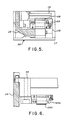
- Figure 5 is an enlarged view of a detail, to a larger scale, of Figures 3 and 4 illustrating details of the radial position sensors;
- Figure 6 is a sectional view taken along line A-A of Figure 3 illustrating the detail of the axial position sensor;
- Figure 7 is a sectional view illustrating an embodiment of a single module gimbal configured as an alternative to the two module approach shown in Figure 2;
- Figure 8 diagrammatically illustrates an embodiment of a three gimbal stack in which the top gimbal closest to the payload is a magnetic gimbal;
- Figure 9 diagrammatically illustrates an embodiment of a three gimbal stack in which the bottom gimbal is a magnetic gimbal;
- Figure 10 illustrates an embodiment of a functional control block diagram for the configuration of Figure 8; and
- Figure 11 illustrates an embodiment of a functional control block diagram for the configuration of Figure 9.
- Referring to Figure 1 the
numeral 11 designates the magnetic isolating and pointing gimbal which replaces a conventional gimbal and isolator and supports apayload 10 which must be precision pointed and simultaneously isolated from vibration disturbances. Themagnetic gimbal 11 is attached to aconventional gimbal 12, for multi-axis course pointing or directly to thestructural interface 13, depending upon requirements. It is at thestructural interface 13 that the primary sources of vibration disturbances are present which are attentuated by themagnetic gimbal 11 so as to allow the vibrationsensitive payload 10 properly to operate and be pointed. With thegimbal 11 positioned as shown in Figure 1, secondary disturbances may also be emitted by thegimbal 12 which require attentuation by themagnetic gimbal 11. - The details of how this invention would be applied to the system of Figure 1 to replace a conventional gimbal assembly and separate isolator is shown in Figure 2. Referring to Figure 2, the
magnetic gimbal assembly 11 is attached to the vibration and pointingsensitive payload 10. In this embodiment, the gimbal assembly is split into two modules, anaxial module 14 and atorque module 15. As shown, these provide for mounting through the centre of mass of thepayload 10. However, thegimbal 11 could also be configured to attach to a payload structure and allow thepayload 10 to be offset from the gimbal axis. Eachmodule housing shaft 17, 17a, a linear, two-axis, large-gap, radialmagnetic actuator radial armature sensor electronics package cover 21, 21a. Also incorporated, but not shown, are position and magnetic flux sensors. Depending on the embodiment, theelectronics package 20 can be mounted elsewhere, for example with any other electronics, not herein shown. Theaxial module 14 incorporates a set of linear, large-gap, axialmagnetic actuators axial armature 23. Thetorque module 15, in addition to the items already mentioned, includes a large-gap, ironless armature brushlessDC torque motor rotational position resolver - The
torque motor motor such torque motor - Support and levitation of the
payload 10 are provided in two-degrees of freedom by operating theradial actuators axial actuators radial actuators torque motor magnetic actuators magnetic armatures torque motor brushless DC motor gap position resolver resolver resolver magnetic actuators magnetic gimbal 11 over a large fraction of the air gap and provides a very linear force-to-force command control for system decoupling. The use of the large gapironless armature torquer - Referring now to Figures 3 and 4, the location of
position sensors radial actuators sensors 28, 28a, are integrated intoadjustable holders 29, 29a which are in turn mounted on thehousing radial armature sensors 28b are mounted in theholders 29b and are positioned to sense theaxial armature 23. In this case anintermediate plate 30 is used to mount to thehousing 16 and to locate theaxial actuators 22a and thesensors 28b relative to theaxial armature 23. This is better shown in Figure 6. If other sensors are used, theholders - Again referring to Figures 3 and 4, the motion of the levitated
shafts 17, 17a and thepayload 10 are constrained by a series of interlocking surfaces which function as stops 26, 26a and 27, 27a. Although not shown in the figures, a series of interlocking tabs can be incorporated in the surfaces of thestops shafts 17, 17a to thehousings - Figure 3 shows the relative positions of the opposed, large-gap,
axial actuators position sensors 28b with respect to theaxial armature 23. In this view, the entire levitated assembly is shown translated to the left. By comparing the stop surfaces 27 of Figure 3 to those of 27a in Figure 4 the function of these surfaces as motion limiters can be better understood. - Figure 4 shows the
torque module 15. Theradial actuator 18a and sensor 28a mounting and functions are as defined for the axial module. The difference lies in replacing theaxial actuators gap position resolver armature torque motor - Figure 7 shows an alternative to the gimbal configuration of Figure 2 for
gimbal 11, or could be used for thebase gimbal 12 of Figure 1. Figure 7 incorporates in one compact module, ashaft 17 attached to apayload 10, ahousing 16, two linear, two-axis, large-gap, radialmagnetic actuators radial armature axial armature 23, a set of linear, large-gap, axialmagnetic actuators armature torque motor gap resolver magnetic armatures electrical cable assembly 31 which provides for electrical connections across the magnetic gaps. These could also be not only electrical cabling but fibreoptic cables, optical transmitters, transformers, tuned cavities, or capacitive couplers. - The functional control loop structure for a system utilising the magnetic isolating and pointing gimbal depends on the pointing objective of the original gimbal system and on which standard gimbal is replaced with the magnetic gimbal. As with the add-on isolation systems, the complexity of the magnetic control loops for the magnetic gimbal system depends, in general, on how close the magnetic interface is placed with respect to the payload. Two configurations, shown in Figures 8 and 9, that have been considered for application of the magnetic isolating and pointing gimbal can be used to illustrate this control loop variability.
- In the first configuration, of Figure 8, the
magnetic gimbal 11 is placed at the top of the gimbal stack and serves as thepayload 10 attach structure. Inertial pointing of thepayload 10 around the Xp and Yp axis as shown in Figure 8 is achieved using the radial magnetic actuators for the Yp axis and the torque motor for the Xp axis. Thesecond level gimbals magnetic gimbal 11. To provide isolation in the other four degrees of freedom the radial and axial actuators provide translational and Zp axis rotational positioning of the gimbal rotor with respect to the gimbal stator. - In the functional block diagram of Figure 10 the separate pointing and positioning functions are shown by the upper and lower control loops, respectively. The driving terms for the bottom loop,D and ⊖ZD, represent the translational and Zp axis rotational motion of the stator side of the magnetic gimbal at the control point. The centering control point referred to in Figure 10 can be arbitrarily chosen, but is most conveniently defined as the centroid of the rotor.

- Isolation characteristics of the four centering loops, defined by the transform from disturbance input to payload motion, is determined largely by the form of isolator compensators. Disturbance isolation around the inertial pointing axes is determined by the bandwidth of the inertial compensators and by the accuracy of payload disturbance torque estimates.
- The blocks of Figure 10 include an inertial pointing compensation matrix function designated A. This is a control compensation block and is identified as a matrix (with two inertial error signals ⊖PXE, ⊖PYE, as input and two torque commands TXC, TYC, as output). The compensation block is likely to consist of two single channel compensators, one for each pointing control axis. Compensation may be implemented in analogue circuitry or in an on-board digital processor.
- An inertial angular motion sensor function is designated B and is a sensor to detect payload inertial motion. Outputs ⊖px, ⊖py, from the sensors provide the signals, one for each pointing axis, on which the pointing loops are closed. A likely candidate for the motion sensor is a strapdown gyro package.
- A software transform to magnetic actuator and torque motor frames function is designated block C. This is a computation block which takes pointing torque commands in the payload inertial frame and isolation force and torque commands in the payload frame and generates torque commands for the gimbal motor and force commands for the radial and axial magnetic actuators. While referred to as a software transform, the block can be implemented in analogue circuitry. The transform is determined by the orientation and position of each of the actuators and of the gimbal motor in the payload frame and will be a function of the upper gimbal angle.
-
Torque motor - A payload and rotor dynamics function is designated block E and provides equations of motion for the payload and the rotor side of the upper gimbal structure.
- Radial and axial magnetic actuators, 18, 18a, 22 and 22a, respectively, are designated as function by block F. These are force actuators for controlling the payload in translation and around axes Yp and Zp normal to gimbal axis Xp. An isolation compensation matrix function is designated block G and includes a single compensation filter for each isolation channel, three translation and one rotation around the payload line of sight.
- A software transform to centering control point function is designated block H and is a transformation matrix relating relative motion at the magnetic interface as detected by the gap sensors to payload motion (with respect to the stator structure) at the payload isolation control point (a point fixed with respect to the payload).
-
Gap sensor - A geometric transform from isolation control point to actuator gaps function is designated block J. This represents physical transformation (as opposed to the software transformation) relating motion at the isolation control point (noted in block G) to relative motion at the actuators. This is the inverse of the transformation in block G.
- The second configuration example of Figure 9 employs the
magnetic gimbal 11 between the twostandard gimbals gimbal support structure 13. In this configuration the base ormagnetic gimbal 11 is used only for manoeuvres to prevent the angle between the payload Yp axis and the gimbal 12 axis from growing too large. In the inertial pointing mode, the magnetic gimbal angle is positioned to a fixed value. The remaining five degrees of freedom of the magnetic gimbal rotor are controlled with magnetic centering loops. Thus, all magnetic gimbal loops have the same relative positioning control objective. - Figure 11 shows a functional block diagram of the magnetic gimbal control loops for the second configuration of Figure 9. Isolation characteristics in the five magnetic actuator control axes are determined by the isolation compensation matrix which may be implemented digitally or in analogue circuitry.
- The configuration of Figure 11 represents a gimbal pointing mode of operation for the magnetic gimbla. In this configuration the magnetic actuators are used solely for isolation. The gimbal motor is used to drive the bottom gimbal to some commanded fimbal orientation. Figure 11 includes the same function blocks C-J as have been described in relation to Figure 10. Block Aʹ of Figure 11 replaces block A of Figure 10 and, block Bʹ of Figure 11 replaces block B of Figure 10. However, it should be noted that each of the isolation transform blocks shown in Figure 11 must account for an angular centering (or isolation) control loop around the axes normal to the magnetic gimbal axis.
- A gimbal angle control compensation function is designated block Aʹ and includes the control compensation filter for the gimbal angle control loop. The compensation may be implemented in a control processor in analogue circuitry.
-
Resolver - The foregoing has described a magnetic isolation and pointing gimbal apparatus providing an improvement in gimbal systems. It provides not only support functions but also provides multidegree of freedom pointing capability and simultaneous six degrees of freedom bi-directional disturbance isolation. By integrating the support, isolation and pointing functions within one contiguous assembly, a major saving in mechanical, structural, electrical and control systems impact and complexity can be made in comparison to separate isolator and gimbal assemblies.
- The savings are realised by replacing one of the standard gimbals with a magnetic gimbal comprising a configuration of radial and axial magnetic actuators arranged with respect to the gimbal axis of rotation. The actuators and the associated control circuits thus provide frictionless rotary bearings at the gimbal radial and axial interface which allows relative and inertial rotation control normal to the gimbal axis. Rotational control around the gimbal axis itself is provided by an ironless armature DC motor. The control loops for the magnetic gimbal are similar to those employed with the magnetic add-on systems. However, because the gimbal control replaces one of the interface loops, the total number of control loops required when using the magnetic gimbal is one less than the number required when using an add-on system.
Claims (14)
a housing (16, 16a);
a shaft (17, 17a) rotatably mounted in the housing and having a centroidal axis extending coaxially within the housing;
a linear, two-axis, large-gap, radial magnetic actuator (18, 18a) mounted in the housing concentrically with the shaft;
a radial armature (19, 19a) mounted on the shaft adjacent the radial magnetic actuator;
a set of linear, large-gap, axial magnetic actuators (22, 22a) mounted in the housing;
an axial armature (23) connected to the shaft and extending between the axial magnetic acutators;
a torque motor (24, 24a, 24b) connected to the shaft; and
a large-gap, rotational position sensor (25, 25a) having a first portion connected to the shaft and a second portion connected to the housing.
a housing (16, 16a) including an axial module (14) connected to one side of a payload (10) and a torque module (15) connected to an opposite side of the payload (10);
a shaft (17, 17a) rotatably mounted in the housing and having a centroidal axis entending coaxially within the housing;
a linear, two-axis, large-gap, radial magnetic actuator (18, 18a) mounted in the housing concentrically with the shaft;
a radial armature (19, 19a) mounted on the shaft adjacent the radial magnetic actuator;
a set of linear, large-gap, axial magnetic actuators (22, 22a) mounted in the axial module (14);
an axial armature (23) in the axial module, connected to the shaft and extending between the axial magnetic actuators;
a torque motor (24, 24a, 24b) in the torque module connected to the shaft; and
a large-gap, rotational position sensor (25, 25a) in the torque module, having a first portion connected to the shaft and a second portion connected to the housing.
a housing (16, 16a) including an axial module (14) connected to one side of a payload (10) and a torque module (15) connected to an opposite side of the payload;
a shaft (17, 17a) rotatably mounted in the housing and having a centroidal axis extending coaxially within the housing;
a linear, two axis, large-gap, radial magnetic actuator (18, 18a) mounted in the housing concentrically with the shaft;
a radial armature (19, 19a) mounted on the shaft adjacent the radial magnetic actuator;
a set of linear, large-gap, axial magnetic actuators (22, 22a) mounted in the axial module (14);
an axial armature (23) in the axial module, connected to the shaft and extending between the axial magnetic actuators;
a torque motor (24, 24a, 24b) in the torque module (15) connected to the shaft;
a large gap, rotational position sensor (25, 25a) in the torque module, having a first portion connected to the shaft and a second portion connected to the housing;
a sensor electronics package (20, 20a) mounted in each of the module (14, 15); and
a cover (21, 21a) mounted on each of the modules adjacent the sensor electronics package.
Applications Claiming Priority (2)
| Application Number | Priority Date | Filing Date | Title |
|---|---|---|---|
| US06/885,627 US4803413A (en) | 1986-07-15 | 1986-07-15 | Magnetic isolating and pointing gimbal apparatus |
| US885627 | 1986-07-15 |
Publications (3)
| Publication Number | Publication Date |
|---|---|
| EP0253615A2 true EP0253615A2 (en) | 1988-01-20 |
| EP0253615A3 EP0253615A3 (en) | 1990-04-11 |
| EP0253615B1 EP0253615B1 (en) | 1993-05-26 |
Family
ID=25387344
Family Applications (1)
| Application Number | Title | Priority Date | Filing Date |
|---|---|---|---|
| EP87306191A Expired - Lifetime EP0253615B1 (en) | 1986-07-15 | 1987-07-13 | Magnetic isolating and pointing gimbal apparatus |
Country Status (4)
| Country | Link |
|---|---|
| US (1) | US4803413A (en) |
| EP (1) | EP0253615B1 (en) |
| JP (1) | JP2529860B2 (en) |
| DE (1) | DE3785973T2 (en) |
Cited By (1)
| Publication number | Priority date | Publication date | Assignee | Title |
|---|---|---|---|---|
| EP1271100A1 (en) * | 2001-06-28 | 2003-01-02 | Northrop Grumman | Motion and trajectory data generator for a multi-gimbaled rotating platform |
Families Citing this family (61)
| Publication number | Priority date | Publication date | Assignee | Title |
|---|---|---|---|---|
| US5197341A (en) * | 1991-06-20 | 1993-03-30 | The United States Of America As Represented By The Secretary Of The Air Force | Payload attitude control tester |
| US5889670A (en) | 1991-10-24 | 1999-03-30 | Immersion Corporation | Method and apparatus for tactilely responsive user interface |
| US5274314A (en) * | 1993-02-12 | 1993-12-28 | Texas Instruments Incorporated | Adaptive friction compensator |
| US5739811A (en) * | 1993-07-16 | 1998-04-14 | Immersion Human Interface Corporation | Method and apparatus for controlling human-computer interface systems providing force feedback |
| US5731804A (en) | 1995-01-18 | 1998-03-24 | Immersion Human Interface Corp. | Method and apparatus for providing high bandwidth, low noise mechanical I/O for computer systems |
| US5701140A (en) * | 1993-07-16 | 1997-12-23 | Immersion Human Interface Corp. | Method and apparatus for providing a cursor control interface with force feedback |
| US5734373A (en) * | 1993-07-16 | 1998-03-31 | Immersion Human Interface Corporation | Method and apparatus for controlling force feedback interface systems utilizing a host computer |
| US6437771B1 (en) * | 1995-01-18 | 2002-08-20 | Immersion Corporation | Force feedback device including flexure member between actuator and user object |
| US5805140A (en) | 1993-07-16 | 1998-09-08 | Immersion Corporation | High bandwidth force feedback interface using voice coils and flexures |
| US5724264A (en) * | 1993-07-16 | 1998-03-03 | Immersion Human Interface Corp. | Method and apparatus for tracking the position and orientation of a stylus and for digitizing a 3-D object |
| US5721566A (en) * | 1995-01-18 | 1998-02-24 | Immersion Human Interface Corp. | Method and apparatus for providing damping force feedback |
| US5821920A (en) * | 1994-07-14 | 1998-10-13 | Immersion Human Interface Corporation | Control input device for interfacing an elongated flexible object with a computer system |
| US5642469A (en) | 1994-11-03 | 1997-06-24 | University Of Washington | Direct-drive manipulator for pen-based force display |
| US6400352B1 (en) | 1995-01-18 | 2002-06-04 | Immersion Corporation | Mechanical and force transmission for force feedback devices |
| US6850222B1 (en) | 1995-01-18 | 2005-02-01 | Immersion Corporation | Passive force feedback for computer interface devices |
| US5691898A (en) * | 1995-09-27 | 1997-11-25 | Immersion Human Interface Corp. | Safe and low cost computer peripherals with force feedback for consumer applications |
| US6166723A (en) * | 1995-11-17 | 2000-12-26 | Immersion Corporation | Mouse interface device providing force feedback |
| US7113166B1 (en) | 1995-06-09 | 2006-09-26 | Immersion Corporation | Force feedback devices using fluid braking |
| US6697748B1 (en) | 1995-08-07 | 2004-02-24 | Immersion Corporation | Digitizing system and rotary table for determining 3-D geometry of an object |
| US5999168A (en) * | 1995-09-27 | 1999-12-07 | Immersion Corporation | Haptic accelerator for force feedback computer peripherals |
| US5959613A (en) | 1995-12-01 | 1999-09-28 | Immersion Corporation | Method and apparatus for shaping force signals for a force feedback device |
| US6704001B1 (en) * | 1995-11-17 | 2004-03-09 | Immersion Corporation | Force feedback device including actuator with moving magnet |
| US6219032B1 (en) | 1995-12-01 | 2001-04-17 | Immersion Corporation | Method for providing force feedback to a user of an interface device based on interactions of a controlled cursor with graphical elements in a graphical user interface |
| US7027032B2 (en) * | 1995-12-01 | 2006-04-11 | Immersion Corporation | Designing force sensations for force feedback computer applications |
| US6028593A (en) * | 1995-12-01 | 2000-02-22 | Immersion Corporation | Method and apparatus for providing simulated physical interactions within computer generated environments |
| US6147674A (en) | 1995-12-01 | 2000-11-14 | Immersion Corporation | Method and apparatus for designing force sensations in force feedback computer applications |
| US8508469B1 (en) | 1995-12-01 | 2013-08-13 | Immersion Corporation | Networked applications including haptic feedback |
| US6078308A (en) * | 1995-12-13 | 2000-06-20 | Immersion Corporation | Graphical click surfaces for force feedback applications to provide user selection using cursor interaction with a trigger position within a boundary of a graphical object |
| US6859819B1 (en) | 1995-12-13 | 2005-02-22 | Immersion Corporation | Force feedback enabled over a computer network |
| US6050718A (en) * | 1996-03-28 | 2000-04-18 | Immersion Corporation | Method and apparatus for providing high bandwidth force feedback with improved actuator feel |
| US6374255B1 (en) * | 1996-05-21 | 2002-04-16 | Immersion Corporation | Haptic authoring |
| US6024576A (en) | 1996-09-06 | 2000-02-15 | Immersion Corporation | Hemispherical, high bandwidth mechanical interface for computer systems |
| US5828197A (en) | 1996-10-25 | 1998-10-27 | Immersion Human Interface Corporation | Mechanical interface having multiple grounded actuators |
| CA2278726C (en) * | 1997-01-27 | 2004-08-31 | Immersion Corporation | Method and apparatus for providing high bandwidth, realistic force feedback including an improved actuator |
| US6020876A (en) | 1997-04-14 | 2000-02-01 | Immersion Corporation | Force feedback interface with selective disturbance filter |
| US6020875A (en) * | 1997-10-31 | 2000-02-01 | Immersion Corporation | High fidelity mechanical transmission system and interface device |
| US6104382A (en) | 1997-10-31 | 2000-08-15 | Immersion Corporation | Force feedback transmission mechanisms |
| US6211861B1 (en) * | 1998-06-23 | 2001-04-03 | Immersion Corporation | Tactile mouse device |
| US6256011B1 (en) * | 1997-12-03 | 2001-07-03 | Immersion Corporation | Multi-function control device with force feedback |
| DE19921390B4 (en) * | 1999-05-10 | 2005-06-09 | Eads Astrium Gmbh | Positioning system for a measuring device of a satellite |
| US6693626B1 (en) * | 1999-12-07 | 2004-02-17 | Immersion Corporation | Haptic feedback using a keyboard device |
| US7084854B1 (en) * | 2000-09-28 | 2006-08-01 | Immersion Corporation | Actuator for providing tactile sensations and device for directional tactile sensations |
| IL143255A (en) | 2001-05-20 | 2015-09-24 | Simbionix Ltd | Endoscopic ultrasonography simulation |
| US6904823B2 (en) * | 2002-04-03 | 2005-06-14 | Immersion Corporation | Haptic shifting devices |
| US6834841B2 (en) * | 2002-07-03 | 2004-12-28 | Honeywell International Inc. | Method and system for decoupling structural modes to provide consistent control system performance |
| US8917234B2 (en) | 2002-10-15 | 2014-12-23 | Immersion Corporation | Products and processes for providing force sensations in a user interface |
| US8992322B2 (en) * | 2003-06-09 | 2015-03-31 | Immersion Corporation | Interactive gaming systems with haptic feedback |
| US7850456B2 (en) | 2003-07-15 | 2010-12-14 | Simbionix Ltd. | Surgical simulation device, system and method |
| AU2006299727B2 (en) * | 2005-10-06 | 2011-07-21 | Technological Resources Pty Limited | Gravity gradiometer |
| KR20150044979A (en) | 2006-09-13 | 2015-04-27 | 임머숀 코퍼레이션 | Systems and methods for casino gaming haptics |
| GB0700470D0 (en) * | 2007-01-10 | 2007-02-21 | Cambridge Entpr Ltd | Apparatus and method for acquiring sectional images |
| US8543338B2 (en) | 2007-01-16 | 2013-09-24 | Simbionix Ltd. | System and method for performing computerized simulations for image-guided procedures using a patient specific model |
| US8500451B2 (en) * | 2007-01-16 | 2013-08-06 | Simbionix Ltd. | Preoperative surgical simulation |
| CN100455874C (en) * | 2007-02-08 | 2009-01-28 | 武汉科技大学 | DSP based control-drive integrated two-freedom degree pan |
| US9486292B2 (en) | 2008-02-14 | 2016-11-08 | Immersion Corporation | Systems and methods for real-time winding analysis for knot detection |
| US9104791B2 (en) * | 2009-05-28 | 2015-08-11 | Immersion Corporation | Systems and methods for editing a model of a physical system for a simulation |
| US8542105B2 (en) * | 2009-11-24 | 2013-09-24 | Immersion Corporation | Handheld computer interface with haptic feedback |
| CN101740139B (en) * | 2009-12-14 | 2015-04-15 | 中国电子科技集团公司第五十四研究所 | Load levelling method for elevator mast |
| US9866924B2 (en) | 2013-03-14 | 2018-01-09 | Immersion Corporation | Systems and methods for enhanced television interaction |
| US9837939B1 (en) | 2015-04-01 | 2017-12-05 | Lockheed Martin Corporation | System and method for providing vibration isolation by magnetic levitation |
| CN109949856B (en) * | 2019-03-15 | 2021-01-29 | 天津理工大学 | Modularized six-degree-of-freedom precise micro-motion mechanism based on flexible hinge |
Citations (4)
| Publication number | Priority date | Publication date | Assignee | Title |
|---|---|---|---|---|
| US4088018A (en) * | 1976-02-27 | 1978-05-09 | The United States Of America As Represented By The Administrator Of The National Aeronautics And Space Administration | Magnetic suspension and pointing system |
| DE3213172A1 (en) * | 1982-04-08 | 1983-10-13 | Bbc Brown Boveri & Cie | Non-positively connected electromotive rotary drive for weapon systems |
| EP0177274A2 (en) * | 1984-09-29 | 1986-04-09 | Kabushiki Kaisha Toshiba | Positioning device of magnetic suspension type |
| EP0185765A1 (en) * | 1984-05-18 | 1986-07-02 | Ntn Corporation | Controlled radial magnetic bearing device |
Family Cites Families (3)
| Publication number | Priority date | Publication date | Assignee | Title |
|---|---|---|---|---|
| US3875488A (en) * | 1973-02-15 | 1975-04-01 | Raytheon Co | Inertially stabilized gimbal platform |
| US4403838A (en) * | 1980-10-30 | 1983-09-13 | Rockwell International Corporation | Precision pointing and stabilization system |
| US4498038A (en) * | 1983-02-15 | 1985-02-05 | Malueg Richard M | Stabilization system for soft-mounted platform |
-
1986
- 1986-07-15 US US06/885,627 patent/US4803413A/en not_active Expired - Fee Related
-
1987
- 1987-07-13 DE DE87306191T patent/DE3785973T2/en not_active Expired - Fee Related
- 1987-07-13 EP EP87306191A patent/EP0253615B1/en not_active Expired - Lifetime
- 1987-07-14 JP JP62174060A patent/JP2529860B2/en not_active Expired - Lifetime
Patent Citations (4)
| Publication number | Priority date | Publication date | Assignee | Title |
|---|---|---|---|---|
| US4088018A (en) * | 1976-02-27 | 1978-05-09 | The United States Of America As Represented By The Administrator Of The National Aeronautics And Space Administration | Magnetic suspension and pointing system |
| DE3213172A1 (en) * | 1982-04-08 | 1983-10-13 | Bbc Brown Boveri & Cie | Non-positively connected electromotive rotary drive for weapon systems |
| EP0185765A1 (en) * | 1984-05-18 | 1986-07-02 | Ntn Corporation | Controlled radial magnetic bearing device |
| EP0177274A2 (en) * | 1984-09-29 | 1986-04-09 | Kabushiki Kaisha Toshiba | Positioning device of magnetic suspension type |
Cited By (2)
| Publication number | Priority date | Publication date | Assignee | Title |
|---|---|---|---|---|
| EP1271100A1 (en) * | 2001-06-28 | 2003-01-02 | Northrop Grumman | Motion and trajectory data generator for a multi-gimbaled rotating platform |
| US6687645B2 (en) | 2001-06-28 | 2004-02-03 | Northrop Grumman Corporation | Motion and trajectory data generator for a multi-gimbaled rotating platform |
Also Published As
| Publication number | Publication date |
|---|---|
| JP2529860B2 (en) | 1996-09-04 |
| EP0253615B1 (en) | 1993-05-26 |
| DE3785973D1 (en) | 1993-07-01 |
| EP0253615A3 (en) | 1990-04-11 |
| JPS6329292A (en) | 1988-02-06 |
| US4803413A (en) | 1989-02-07 |
| DE3785973T2 (en) | 1993-09-30 |
Similar Documents
| Publication | Publication Date | Title |
|---|---|---|
| EP0253615B1 (en) | Magnetic isolating and pointing gimbal apparatus | |
| CA1113071A (en) | Strapped down attitude and heading reference system for aircraft employing skewed axis two-degree-of-freedom rate gyros | |
| US5897223A (en) | Stabilized platform system for camera | |
| US4082005A (en) | Spin coupled, angular rate sensitive inertial sensors with mounting structure and method of fabricating and mounting same | |
| US4062600A (en) | Dual-gimbal gyroscope flexure suspension | |
| JPH08505826A (en) | Direct torque control moment gyroscope | |
| US8738317B2 (en) | Inertial measurement device and an aircraft including such a device | |
| US5638303A (en) | Non-contacting isolated stabilized microgravity platform system | |
| EP0245467A4 (en) | Inertial measurement unit. | |
| CN111506118B (en) | Three-degree-of-freedom photoelectric pod driven by orthogonal decoupling torque | |
| WO2017028021A1 (en) | System and method for supporting compact servo system | |
| US4425040A (en) | Ring laser gyroscope cluster for strapped down navigation | |
| US4458536A (en) | Multiaxial vibration sensor | |
| US4290316A (en) | Free-rotor gas-bearing gyroscope having electromagnetic rotor restraint and acceleration output signal | |
| US3748912A (en) | Gyroscope with universally mounted rotor | |
| CA1117786A (en) | Angular accelerometer stabilized pendulum | |
| US3974701A (en) | Spin coupled, angular rate sensitive inertial sensors with optional acceleration sensing capability and method of fabricating same | |
| EP0122745B1 (en) | Damping mechanism for gyroscopes | |
| US3318160A (en) | Vibra-rotor gyroscope | |
| GB2271422A (en) | Compensated inertial guidance system | |
| WO1994012854A1 (en) | Electronically commutated two-axis gyro control system | |
| US4461176A (en) | Miniature gyroscope | |
| RU2771918C2 (en) | Gyroscope | |
| JPH04202B2 (en) | ||
| RU2787311C1 (en) | Control device for stabilizing course-vertical motors |
Legal Events
| Date | Code | Title | Description |
|---|---|---|---|
| PUAI | Public reference made under article 153(3) epc to a published international application that has entered the european phase |
Free format text: ORIGINAL CODE: 0009012 |
|
| AK | Designated contracting states |
Kind code of ref document: A2 Designated state(s): DE FR GB IT |
|
| PUAL | Search report despatched |
Free format text: ORIGINAL CODE: 0009013 |
|
| RHK1 | Main classification (correction) |
Ipc: F16C 39/06 |
|
| AK | Designated contracting states |
Kind code of ref document: A3 Designated state(s): DE FR GB IT |
|
| 17P | Request for examination filed |
Effective date: 19900927 |
|
| 17Q | First examination report despatched |
Effective date: 19910205 |
|
| ITF | It: translation for a ep patent filed |
Owner name: BARZANO' E ZANARDO ROMA S.P.A. |
|
| GRAA | (expected) grant |
Free format text: ORIGINAL CODE: 0009210 |
|
| AK | Designated contracting states |
Kind code of ref document: B1 Designated state(s): DE FR GB IT |
|
| REF | Corresponds to: |
Ref document number: 3785973 Country of ref document: DE Date of ref document: 19930701 |
|
| ET | Fr: translation filed | ||
| PLBE | No opposition filed within time limit |
Free format text: ORIGINAL CODE: 0009261 |
|
| STAA | Information on the status of an ep patent application or granted ep patent |
Free format text: STATUS: NO OPPOSITION FILED WITHIN TIME LIMIT |
|
| 26N | No opposition filed | ||
| PGFP | Annual fee paid to national office [announced via postgrant information from national office to epo] |
Ref country code: FR Payment date: 19980618 Year of fee payment: 12 |
|
| PGFP | Annual fee paid to national office [announced via postgrant information from national office to epo] |
Ref country code: DE Payment date: 19980625 Year of fee payment: 12 |
|
| PGFP | Annual fee paid to national office [announced via postgrant information from national office to epo] |
Ref country code: GB Payment date: 19980626 Year of fee payment: 12 |
|
| PG25 | Lapsed in a contracting state [announced via postgrant information from national office to epo] |
Ref country code: GB Free format text: LAPSE BECAUSE OF NON-PAYMENT OF DUE FEES Effective date: 19990713 |
|
| PG25 | Lapsed in a contracting state [announced via postgrant information from national office to epo] |
Ref country code: FR Free format text: THE PATENT HAS BEEN ANNULLED BY A DECISION OF A NATIONAL AUTHORITY Effective date: 19990731 |
|
| GBPC | Gb: european patent ceased through non-payment of renewal fee |
Effective date: 19990713 |
|
| PG25 | Lapsed in a contracting state [announced via postgrant information from national office to epo] |
Ref country code: DE Free format text: LAPSE BECAUSE OF NON-PAYMENT OF DUE FEES Effective date: 20000503 |
|
| REG | Reference to a national code |
Ref country code: FR Ref legal event code: ST |
|
| PG25 | Lapsed in a contracting state [announced via postgrant information from national office to epo] |
Ref country code: IT Free format text: LAPSE BECAUSE OF NON-PAYMENT OF DUE FEES;WARNING: LAPSES OF ITALIAN PATENTS WITH EFFECTIVE DATE BEFORE 2007 MAY HAVE OCCURRED AT ANY TIME BEFORE 2007. THE CORRECT EFFECTIVE DATE MAY BE DIFFERENT FROM THE ONE RECORDED. Effective date: 20050713 |