EP0256202A2 - Coupling body for a shockwave-therapeutic apparatus - Google Patents
Coupling body for a shockwave-therapeutic apparatus Download PDFInfo
- Publication number
- EP0256202A2 EP0256202A2 EP87101802A EP87101802A EP0256202A2 EP 0256202 A2 EP0256202 A2 EP 0256202A2 EP 87101802 A EP87101802 A EP 87101802A EP 87101802 A EP87101802 A EP 87101802A EP 0256202 A2 EP0256202 A2 EP 0256202A2
- Authority
- EP
- European Patent Office
- Prior art keywords
- shock wave
- coupling body
- wave sensor
- sensor
- body according
- Prior art date
- Legal status (The legal status is an assumption and is not a legal conclusion. Google has not performed a legal analysis and makes no representation as to the accuracy of the status listed.)
- Withdrawn
Links
Images

Classifications
-
- A—HUMAN NECESSITIES
- A61—MEDICAL OR VETERINARY SCIENCE; HYGIENE
- A61B—DIAGNOSIS; SURGERY; IDENTIFICATION
- A61B17/00—Surgical instruments, devices or methods, e.g. tourniquets
- A61B17/22—Implements for squeezing-off ulcers or the like on the inside of inner organs of the body; Implements for scraping-out cavities of body organs, e.g. bones; Calculus removers; Calculus smashing apparatus; Apparatus for removing obstructions in blood vessels, not otherwise provided for
- A61B17/225—Implements for squeezing-off ulcers or the like on the inside of inner organs of the body; Implements for scraping-out cavities of body organs, e.g. bones; Calculus removers; Calculus smashing apparatus; Apparatus for removing obstructions in blood vessels, not otherwise provided for for extracorporeal shock wave lithotripsy [ESWL], e.g. by using ultrasonic waves
- A61B17/2251—Implements for squeezing-off ulcers or the like on the inside of inner organs of the body; Implements for scraping-out cavities of body organs, e.g. bones; Calculus removers; Calculus smashing apparatus; Apparatus for removing obstructions in blood vessels, not otherwise provided for for extracorporeal shock wave lithotripsy [ESWL], e.g. by using ultrasonic waves characterised by coupling elements between the apparatus, e.g. shock wave apparatus or locating means, and the patient, e.g. details of bags, pressure control of bag on patient
-
- G—PHYSICS
- G01—MEASURING; TESTING
- G01H—MEASUREMENT OF MECHANICAL VIBRATIONS OR ULTRASONIC, SONIC OR INFRASONIC WAVES
- G01H3/00—Measuring characteristics of vibrations by using a detector in a fluid
- G01H3/005—Testing or calibrating of detectors covered by the subgroups of G01H3/00
-
- G—PHYSICS
- G10—MUSICAL INSTRUMENTS; ACOUSTICS
- G10K—SOUND-PRODUCING DEVICES; METHODS OR DEVICES FOR PROTECTING AGAINST, OR FOR DAMPING, NOISE OR OTHER ACOUSTIC WAVES IN GENERAL; ACOUSTICS NOT OTHERWISE PROVIDED FOR
- G10K11/00—Methods or devices for transmitting, conducting or directing sound in general; Methods or devices for protecting against, or for damping, noise or other acoustic waves in general
- G10K11/004—Mounting transducers, e.g. provided with mechanical moving or orienting device
-
- A—HUMAN NECESSITIES
- A61—MEDICAL OR VETERINARY SCIENCE; HYGIENE
- A61B—DIAGNOSIS; SURGERY; IDENTIFICATION
- A61B17/00—Surgical instruments, devices or methods, e.g. tourniquets
- A61B17/22—Implements for squeezing-off ulcers or the like on the inside of inner organs of the body; Implements for scraping-out cavities of body organs, e.g. bones; Calculus removers; Calculus smashing apparatus; Apparatus for removing obstructions in blood vessels, not otherwise provided for
- A61B17/225—Implements for squeezing-off ulcers or the like on the inside of inner organs of the body; Implements for scraping-out cavities of body organs, e.g. bones; Calculus removers; Calculus smashing apparatus; Apparatus for removing obstructions in blood vessels, not otherwise provided for for extracorporeal shock wave lithotripsy [ESWL], e.g. by using ultrasonic waves
- A61B17/2251—Implements for squeezing-off ulcers or the like on the inside of inner organs of the body; Implements for scraping-out cavities of body organs, e.g. bones; Calculus removers; Calculus smashing apparatus; Apparatus for removing obstructions in blood vessels, not otherwise provided for for extracorporeal shock wave lithotripsy [ESWL], e.g. by using ultrasonic waves characterised by coupling elements between the apparatus, e.g. shock wave apparatus or locating means, and the patient, e.g. details of bags, pressure control of bag on patient
- A61B2017/2253—Implements for squeezing-off ulcers or the like on the inside of inner organs of the body; Implements for scraping-out cavities of body organs, e.g. bones; Calculus removers; Calculus smashing apparatus; Apparatus for removing obstructions in blood vessels, not otherwise provided for for extracorporeal shock wave lithotripsy [ESWL], e.g. by using ultrasonic waves characterised by coupling elements between the apparatus, e.g. shock wave apparatus or locating means, and the patient, e.g. details of bags, pressure control of bag on patient using a coupling gel or liquid
-
- A—HUMAN NECESSITIES
- A61—MEDICAL OR VETERINARY SCIENCE; HYGIENE
- A61B—DIAGNOSIS; SURGERY; IDENTIFICATION
- A61B90/00—Instruments, implements or accessories specially adapted for surgery or diagnosis and not covered by any of the groups A61B1/00 - A61B50/00, e.g. for luxation treatment or for protecting wound edges
- A61B90/06—Measuring instruments not otherwise provided for
- A61B2090/064—Measuring instruments not otherwise provided for for measuring force, pressure or mechanical tension
Definitions
- the invention relates to a coupling body for coupling a shock wave, in particular for the transmission of shock waves from a shock wave source to a patient to be treated, the coupling body being formed from an elastic, dimensionally stable material with moist outer surfaces.
- a shock wave source e.g. B. a lithotripter for kidney stone destruction, in which a shock wave pulse is generated with the help of an electrical coil (see. DE-OS 33 28 051)
- checks of the function are appropriate from time to time. Such checks relate, for example, to the focus position, the pressure distribution or the pressure amplitude of the shock wave pulse. Such checks are regularly useful when using the shock wave source; however, they are also necessary for initial assembly, after modifications, for service or for repairs. If, for example, the means focusing the shock wave pulse (such as an acoustic lens or a reflector) is exchanged, it must be checked afterwards whether the focus position is identical to the situation before the exchange.
- the means focusing the shock wave pulse such as an acoustic lens or a reflector
- a shock wave sensor which can be used in particular for lithotripsy, is known from DE-OS 34 37 976.
- the invention is based on the consideration that both shock wave sensors, in particular electrical pressure measuring elements, as well as test means for functional testing Shock wave indicators come into question.
- a shock wave indicator in addition to the direct observation of the point of impact of the shock wave pulses, a subsequent evaluation, e.g. B. Estimation of the integrally received energy may be possible.
- the handling of the test equipment is important. A loss-free coupling that is as reproducible as possible in a defined geometry is also important.
- the object of the present invention is to design a coupling body of the type mentioned at the outset in such a way that a simple check of the function of the shock wave source is possible after the coupling.
- This object is achieved in that a shock wave sensor is included in the elastic, dimensionally stable material.
- the shock wave sensor which can preferably be designed as an electrical pressure measuring element but also as a shock wave indicator, is preferably embedded in a dimensionally stable hydrogel.
- all test equipment suitable for measuring a shock wave can be used as shock wave sensors, but in particular small electrical pressure sensors and small optical indicators.
- the coupling body has a suitable shape, such as. B. disc or block shape, and can be placed by means of a bracket in a defined relation to the shock wave source on the coupling surface.
- the advantage here is a good coupling of the shock wave pulse to the shock wave sensor.
- Handling in the review the lithotripter function consists essentially of moistening one side of the coupling body, attaching the coupling body to the shock wave source and measuring.
- the transparent hydrogel that is preferably used enables direct observation or even optical detection and evaluation of the front and / or back of a shock wave indicator used as a sensor without dismantling.
- a piezoelectric activated PVDF film as a shock wave sensor, artifacts caused by undesired movement of the measuring film are reduced.
- a shock wave source 1 with its essential elements, namely with a shock wave generator 3, a lead section 5 with focusing means and a coupling-out membrane 7.
- a coupling body 11 which consists of an elastic, dimensionally stable material, in particular is made of the coupling-out membrane 7 a hydrogel with wet surfaces.
- a patient 13 is coupled to the free end face or coupling surface 12 of the concave-convex coupling body 11.
- a shock wave sensor 15 is contained in the coupling body 11.
- the shock wave sensor 15 is an electrical sensor, specifically a piezoceramic or a piezo crystal 17, which is connected to a measuring device 21 via a feed line 19.
- the piezo crystal 17 is preferably in the central region or in the middle of the coupling body 11, i. H. arranged on the central axis 22 of the shock wave source 1. It is also possible to provide a plurality of piezocrystals 17 next to one another, in the radial direction with respect to the central axis 22 or on a ring around the central axis 22.
- the function of the shock wave source 1 can be continuously checked with the aid of the piezo crystal 17 and the measuring device 21.
- the check consists, for example, in monitoring the correct (ie predetermined) pressure amplitude of the shock wave pulse at the location of the shock wave sensor 15.
- B known that given operating parameters of, for example, an operating voltage of 15 kV, a capacitor capacitance of 0.5 uF, a lead length of 20 cm, etc. at the location of the shock wave sensor 15 with proper operation and proper positioning, a predetermined amplitude of the shock wave pulse (reference value ) on must kick.
- the pressure amplitude determined by the shock wave sensor 15 deviates from the reference value by a predetermined percentage during the continuous therapy treatment, which can include up to 1000 shock wave pulses per patient, conclusions can be drawn about possible disturbances in the shock wave source 1.
- the determination of an excessive pressure amplitude can then be used to interrupt the therapy treatment, and a pressure amplitude which is too small can also give rise to the interruption of the therapy measure and subsequent checking of the system.
- the shock wave source 1 can be re-calibrated or adjusted after a possible repair or maintenance.
- an electromagnetic flat coil was used as the shock wave generator 3 and was exchanged for another coil during maintenance, there is the possibility that the center of the new coil is shifted slightly. Accordingly, when a shock wave pulse hits the shock wave sensor 15, the expected reference value will not occur, but a lower value. The coil can be readjusted until the specified reference value is reached. Then it is ensured that the shock wave source 1 has the same properties as before the maintenance or repair.
- the reference value that is used to reset the shock wave source 1 need not be the same as in the so-called "on-line" operation with the patient 13.
- the voltage value operating parameter can only be 12 kV instead of the 15 kV mentioned in the Therapy treatment amount or a range of z. B. drive through 12 kV to 20 kV.
- FIG. 2 the same parts are provided with the same reference symbols as in FIG. 1.
- the shock wave source 1 in turn consists of a shock wave generator 3, a lead section 5 with associated focusing means and a decoupling membrane 7.
- a perforated metal membrane 30 is clamped on the edge in an external holder 9 as a stabilizer.
- the metal membrane 30 has a recess 32 in its center, which runs coaxially to the center axis 22 of the shock wave source 1.
- the cutout 32 is spanned with a partially piezoelectric film, for example a PVDF film 34, which is piezoelectrically activated in its central region, that is to say is polarized.
- an annular lead electrode 36 is provided, which is arranged outside the polarized surface.
- the lead electrodes 36 are connected to lines 19 which lead to a measuring device 21.
- the PVDF film 34 and the ring-shaped discharge electrodes 36 form a shock wave sensor 15.
- Such a shock wave sensor 15 is described in detail in German patent application P 35 45 382.6, the content of which is to be part of the disclosure of the present description.
- the shock wave sensor 15 is embedded in a dimensionally stable, gel-like coupling body 11, which is held by the perforated metal membrane 30.
- the disk-shaped coupling body 11 rests on the decoupling membrane 7 with the support surface kept moist and free of air bubbles.
- the patient to be treated is coupled to the other (also kept moist) support surface.
- the shock wave sensor here comprises a large-area PVDF film 34 provided with cutouts, on each of which a polarization (i.e. piezoelectric activation) is carried out on predetermined small partial areas and a metal contact 40 is evaporated.
- the metal contacts 40 are each connected to a measuring device 21 via a line 19.
- the charge which arises on the activated sensor surface hit by a shock wave pulse is detected galvanically with the aid of the metal contacts 40, passed on galvanically through the lines 19 and in the associated measuring device 21 for a measured value, e.g. B. processed a voltage signal reflecting the temporal pressure curve.
- a measured value e.g. B. processed a voltage signal reflecting the temporal pressure curve.
- several measuring points lying next to one another or also in front of and behind one another are possible at the same time when using several PVDF foils.
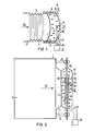
- a gel-like, dimensionally stable coupling body 11 is designed as a "block"; that is, it has such dimensions that the focus F of a shock wave source 1 is still within the coupling body 11. This is indicated by the marginal rays 46, 48.
- the focus plane is close to the coupling surface 12 on the patient side.
- the shock wave indicator 50 consists, for example, of a round ceramic plate, which undergoes material removal under the action of shock waves, or a thin metal foil, especially lead foil, which deforms or bulges under the action of shock waves. Electrical connection lines are therefore not required here.
- the coupling body 11 is positioned in a holder 9 so that the factory-set values for the distance to the shock wave generator 3, for the size of the lead section 5, for the distance to the focusing means, etc. are met.
- the operating personnel can determine on the shock wave indicator 50, by visual inspection on the indicator 50 in the focus plane, whether there is mechanical deformation or ablation at the desired focus point, ie whether the focus F is actually at the predetermined point . If this is not the case, further testing and adjustment work must be carried out.
- the shock wave indicator 50 is preferably provided with a marking which is provided with sectors and circular rings similar to a (throwing or shooting) target. In this way, deviations in the focus position can be recorded quantitatively, which reduces the effort involved in the subsequent adjustment.
Abstract
Description
Die Erfindung betrifft einen Ankoppelkörper für die Ankopplung einer Stoßwelle, insbesondere für die Übertragung von Stoßwellen von einer Stoßwellenquelle zu einem zu behandelnden Patienten, wobei der Ankoppelkörper aus einem elastischen, formstabilen Material mit feuchten Außenflächen gebildet ist.The invention relates to a coupling body for coupling a shock wave, in particular for the transmission of shock waves from a shock wave source to a patient to be treated, the coupling body being formed from an elastic, dimensionally stable material with moist outer surfaces.
Im Betrieb einer Stoßwellenquelle, z. B. eines Lithotripters zur Nierensteinzertrümmerung, bei welchem ein Stoßwellenimpuls mit Hilfe einer elektrischen Spule erzeugt wird (vgl. DE-OS 33 28 051), sind von Zeit zu Zeit Überprüfungen der Funktion angebracht. Solche Überprüfungen betreffen beispielsweise die Fokuslage, die Druckverteilung oder die Druckamplitude des Stoßwellenimpulses. Solche Überprüfungen sind regelmäßig im Einsatz der Stoßwellenquelle zweckmäßig; sie sind aber auch notwendig bei Erstmontage, nach Umbauten, beim Service oder bei Reparatur. Wird beispielsweise das den Stoßwellenimpuls fokussierende Mittel (wie z. B. eine akustische Linse oder ein Reflektor) ausgetauscht, so muß hinterher geprüft werden, ob eine identische Fokuslage im Vergleich zur Situation vor dem Austausch vorhanden ist.In the operation of a shock wave source, e.g. B. a lithotripter for kidney stone destruction, in which a shock wave pulse is generated with the help of an electrical coil (see. DE-OS 33 28 051), checks of the function are appropriate from time to time. Such checks relate, for example, to the focus position, the pressure distribution or the pressure amplitude of the shock wave pulse. Such checks are regularly useful when using the shock wave source; however, they are also necessary for initial assembly, after modifications, for service or for repairs. If, for example, the means focusing the shock wave pulse (such as an acoustic lens or a reflector) is exchanged, it must be checked afterwards whether the focus position is identical to the situation before the exchange.
Ein Stoßwellensensor, der insbesondere für die Lithotripsie verwendet werden kann, ist aus der DE-OS 34 37 976 bekannt.A shock wave sensor, which can be used in particular for lithotripsy, is known from DE-OS 34 37 976.
Die Erfindung beruht auf der Überlegung, daß als Prüfmittel zur Funktionsüberprüfung sowohl Stoßwellensensoren, insbesondere elektrische Druckmeßelemente, als auch Stoßwellenindikatoren infrage kommen. Bei einem Stoßwellenindikator sollte neben der unmittelbaren Beobachtung des Auftreffpunktes der Stoßwellenimpulse eine nachträgliche Auswertung, z. B. Abschätzung, der integral empfangenen Energie möglich sein. Neben der Herstellbarkeit und dem Preis für die Überprüfung ist die Handhabbarkeit des Prüfmittels von Bedeutung. Auch ist eine in definierter Geometrie möglichst reproduzierbare und verlustfreie Ankopplung wichtig.The invention is based on the consideration that both shock wave sensors, in particular electrical pressure measuring elements, as well as test means for functional testing Shock wave indicators come into question. In the case of a shock wave indicator, in addition to the direct observation of the point of impact of the shock wave pulses, a subsequent evaluation, e.g. B. Estimation of the integrally received energy may be possible. In addition to the manufacturability and the price for the inspection, the handling of the test equipment is important. A loss-free coupling that is as reproducible as possible in a defined geometry is also important.
Aufgabe vorliegender Erfindung ist es, einen Ankoppelkörper der eingangs genannten Art so auszubilden, daß nach der Ankopplung eine einfache Überprüfung der Funktion der Stoßwellenquelle möglich ist. Insbesondere soll es während des Normalbetriebs der Stoßwellenquelle, also beispielsweise während einer Lithotripsiebehandlung, möglich sein, die Funktion der Stoßwellenquelle zu überwachen.The object of the present invention is to design a coupling body of the type mentioned at the outset in such a way that a simple check of the function of the shock wave source is possible after the coupling. In particular, it should be possible to monitor the function of the shock wave source during normal operation of the shock wave source, for example during lithotripsy treatment.
Diese Aufgabe wird erfindungsgemäß dadurch gelöst, daß im elastischen, formstabilen Material ein Stoßwellensensor enthalten ist.This object is achieved in that a shock wave sensor is included in the elastic, dimensionally stable material.
Der Stoßwellensensor, der vorzugsweise als elektrisches Druckmeßelement aber auch als ein Stoßwellenindikator ausgeführt sein kann, wird bevorzugt in ein formstabiles Hydrogel eingebettet. Als Stoßwellensensoren kommen prinzipiell alle zur Messung einer Stoßwelle geeigneten Prüfmittel infrage, insbesondere aber kleine elektrische Drucksensoren und kleine optische Indikatoren. Der Ankoppelkörper besitzt eine geeignete Form, wie z. B. Scheiben- oder Klotzform, und kann mittels einer Halterung in definierter Relation zur Stoßwellenquelle auf deren Auskoppelfläche aufgesetzt werden. Dabei ergibt sich als Vorteil eine gute Ankopplung des Stoßwellenimpulses an den Stoßwellensensor. Die Handhabung bei der Überprüfung der Lithotripterfunktion besteht im wesentlichen aus dem Anfeuchten einer Seite des Ankoppelkörpers, dem Befestigen des Ankoppelkörpers an die Stoßwellenquelle und dem Meßvorgang.The shock wave sensor, which can preferably be designed as an electrical pressure measuring element but also as a shock wave indicator, is preferably embedded in a dimensionally stable hydrogel. In principle, all test equipment suitable for measuring a shock wave can be used as shock wave sensors, but in particular small electrical pressure sensors and small optical indicators. The coupling body has a suitable shape, such as. B. disc or block shape, and can be placed by means of a bracket in a defined relation to the shock wave source on the coupling surface. The advantage here is a good coupling of the shock wave pulse to the shock wave sensor. Handling in the review the lithotripter function consists essentially of moistening one side of the coupling body, attaching the coupling body to the shock wave source and measuring.
Das vorzugsweise verwendete durchsichtige Hydrogel ermöglicht eine direkte Betrachtung oder sogar eine optische Erfassung und Auswertung von Vorder- und/oder Rückseite eines als Sensor eingesetzten Stoßwellenindikators ohne Demontage. Bei Einsatz einer piezoelektrischen aktivierten PVDF-Folie als Stoßwellensensor werden Artefakte, die durch ungewünschte Bewegung der Meßfolie hervorgerufen werden, reduziert.The transparent hydrogel that is preferably used enables direct observation or even optical detection and evaluation of the front and / or back of a shock wave indicator used as a sensor without dismantling. When using a piezoelectric activated PVDF film as a shock wave sensor, artifacts caused by undesired movement of the measuring film are reduced.
Weitere Vorteile und Ausgestaltungen der Erfindung ergeben sich aus der folgenden Beschreibung von Ausführungsbeispielen in Verbindung mit den Unteransprüchen. Es zeigen:
- Fig. 1 eine Stoßwellenquelle und einen Ankoppelkörper mit integriertem Piezokristall,
- Fig. 2 eine Stoßwellenquelle und einen Ankoppelkörper mit eingebauter PVDF-Folie bei kapazitiver Ableitung des Meßsignals,
- Fig. 3 einen Ankoppelkörper mit eingebauter PVDF-Folie bei galvanischer Ableitung des Meßsignals und
- Fig. 4 eine Stoßwellenquelle und einen Ankoppelkörper mit eingebautem optischen Stoßwellenindikator.
- 1 shows a shock wave source and a coupling body with an integrated piezo crystal,
- 2 shows a shock wave source and a coupling body with a built-in PVDF film with capacitive derivation of the measurement signal,
- Fig. 3 shows a coupling body with built-in PVDF film with galvanic derivation of the measurement signal and
- Fig. 4 shows a shock wave source and a coupling body with a built-in optical shock wave indicator.
In Fig. 1 ist eine Stoßwellenquelle 1 mit ihren wesentlichen Elementen, nämlich mit einem Stoßwellengenerator 3, einer Vorlaufstrecke 5 mit Fokussierungsmittel und einer Auskoppelmembran 7, dargestellt. Von einer hohlzylindrischen Halterung 9 gestützt, ist an die Auskoppelmembran 7 ein Ankoppelkörper 11 angelegt, der aus einem elastischen, formstabilen Material besteht, insbesondere aus einem Hydrogel mit feuchten Oberflächen. An der freien Stirnseite oder Ankoppelfläche 12 des konkav-konvexen Ankoppelkörpers 11 ist ein Patient 13 angekoppelt. Der Ankoppelkörper 11 dient zur Übertragung von Stoßwellenimpulsen von der Stoßwellenquelle 1 zum Patienten 13. Diese Anordnung ist in der deutschen Patentanmeldung P 36 05 277 (= VPA 86 P 3062) detailliert beschrieben.1 shows a
In dem Ankoppelkörper 11 ist ein Stoßwellensensor 15 enthalten. In der gezeigten Ausführungsform ist der Stoßwellensensor 15 ein elektrischer Sensor, speziell eine Piezokeramik oder ein Piezokristall 17, welcher über eine Zuleitung 19 an ein Meßgerät 21 angeschlossen ist. Der Piezokristall 17 ist vorzugsweise im Zentralbereich oder in der Mitte des Ankoppelkörpers 11, d. h. auf der Zentralachse 22 der Stoßwellenquelle 1, angeordnet. Es ist auch möglich, mehrere Piezokristalle 17 nebeneinander vorzusehen, und zwar in radialer Richtung bezüglich der Zentralachse 22 oder auf einem Ring um die Zentralachse 22 herum.A
Im normalen Betrieb der Stoßwellenquelle 1, also beispielsweise während der Lithotripsiebehandlung des Patienten 13, kann mit Hilfe des Piezokristalls 17 und des Meßgeräts 21 fortlaufend die Funktion der Stoßwellenquelle 1 überprüft werden. Die Überprüfung besteht beispielsweise in der Überwachung der korrekten (d. h. vorgegebenen) Druckamplitude des Stoßwellenimpulses am Ort des Stoßwellensensors 15. Durch eine werkseitig zuvor vorgenommene Referenzmessung sei es z. B. bekannt, daß bei vorgegebenen Betriebsparametern von beispielsweise einer Betriebsspannung von 15 kV, einer Kondensatorkapazität von 0,5 µF, einer Vorlaufstreckenlänge von 20 cm, usw. am Ort des Stoßwellensensors 15 bei ordnungsgemäßem Betrieb und ordnungsgemäßer Positionierung eine vorgegebene Amplitude des Stoßwellenimpulses (Referenzwert) auf treten muß. Weicht während der fortlaufenden Therapiebehandlung, die bis zu 1000 Stoßwellenimpulse pro Patient umfassen kann, die vom Stoßwellensensor 15 ermittelte Druckamplitude um einen vorgegebenen Prozentsatz von dem Referenzwert ab, so lassen sich daraus Rückschlüsse auf mögliche Störungen in der Stoßwellenquelle 1 ziehen. Die Feststellung einer überhöhten Druckamplitude kann dann benutzt werden, die Therapiebehandlung zu unterbrechen, und eine zu kleine Druckamplitude kann ebenfalls Anlaß zur Unterbrechung der Therapiemaßnahme und darauffolgende Überprüfung der Anlage geben.During normal operation of the
Darüber hinaus kann mit dem in den Ankoppelkörper 11 eingebauten Stoßwellensensor 15 die Stoßwellenquelle 1 nach einer eventuellen Reparatur oder Wartung neu geeicht oder eingestellt werden. Wurde beispielsweise als Stoßwellengenerator 3 bekanntermaßen eine elektromagnetische Flach-Spule eingesetzt, die bei der Wartung gegen eine andere Spule ausgetauscht wurde, so besteht die Möglichkeit, daß das Zentrum der neuen Spule geringfügig verschoben ist. Demzufolge wird bei Auftreffen eines Stoßwellenimpulses am Stoßwellensensor 15 nicht der erwartete Referenzwert auftreten, sondern ein geringerer Wert. Die Spule kann so lange neu justiert werden, bis der vorgegebene Referenzwert erreicht wird. Dann ist sichergestellt, daß die Stoßwellenquelle 1 die gleichen Eigenschaften aufweist wie vor der Wartung oder Reparatur.In addition, with the
Der Referenzwert, der zur Neueinstellung der Stoßwellenquelle 1 herangezogen wird, braucht nicht der gleiche zu sein wie im sogenannten "On-Line"-Betrieb mit dem Patienten 13. So beispielsweise kann der Betriebsparameter Spannungswert nur 12 kV anstelle von den erwähnten 15 kV bei der Therapiebehandlung betragen oder einen Bereich von z. B. 12 kV bis 20 kV durchfahren.The reference value that is used to reset the
In Fig. 2 sind gleiche Teile mit gleichen Bezugszeichen versehen wie in Fig. 1.In FIG. 2, the same parts are provided with the same reference symbols as in FIG. 1.
Die Stoßwellenquelle 1 besteht wiederum aus einem Stoßwellengenerator 3, einer Vorlaufstrecke 5 mit zugehörigem Fokussierungsmittel und einer Auskoppelmembran 7. In einer außenliegenden Halterung 9 ist randseitig eine perforierte Metallmembran 30 als Stabilisator eingespannt. Die Metallmembran 30 besitzt in ihrem Zentrum eine Aussparung 32, welche koaxial zur Zentrumsachse 22 der Stoßwellenquelle 1 verläuft. Die Aussparung 32 ist mit einer teilweise piezoelektrischen Folie, beispielsweise einer PVDF-Folie 34 überspannt, die in ihrem zentralen Bereich piezoelektrisch aktiviert, also polarisiert ist. Auf beiden Seiten der PVDF-Folie 34 ist je eine ringförmige Ableitelektrode 36 vorgesehen, welche außerhalb der polarisierten Fläche angeordnet ist. Die Ableitelektroden 36 sind an Leitungen 19 angeschlossen, welche zu einem Meßgerät 21 führen. Die PVDF-Folie 34 und die ringförmigen Ableitelektroden 36 bilden in diesem Ausführungsbeispiel einen Stoßwellensensor 15. Ein solcher Stoßwellensensor 15 ist ausführlich in der deutschen Patentanmeldung P 35 45 382.6 beschrieben, deren Inhalt zur Offenbarung vorliegender Beschreibung gehören soll.The
Der Stoßwellensensor 15 ist in einem formstabilen, gelartigen Ankoppelkörper 11 eingebettet, welcher durch die perforierte Metallmembran 30 gehalten wird. Der scheibenförmig ausgebildete Ankoppelkörper 11 liegt mit feuchtgehaltener Auflagefläche luftblasenfrei an der Auskoppelmembran 7 an. Auf der anderen (ebenfalls feucht gehaltenen) Auflagefläche wird der zu behandelnde Patient angekoppelt.The
Das Auftreffen eines Stoßwellenimpulses auf die PVDF-Folie 34 wird durch kapazitive Messung über die Ableitelektroden 36 vom Meßgerät 21 ermittelt. Aus dem Meßwert kön nen Rückschlüsse auf die Amplitude des Stoßwellenimpulses gezogen werden. Funktionsweise und Handhabung des Ankoppelkörpers 11 sind identisch zu denen gemäß der Ausführungsform nach Fig. 1. Auch hier ist ein "On-Line"-Betrieb, also eine fortlaufende Überwachung der Stoßwellenimpulse während der Therapiebehandlung, möglich.The impact of a shock wave pulse on the
In Fig. 3 ist ein Ankoppelkörper 11 mit integriertem Stoßwellensensor 15 allein dargestellt. Der Stoßwellensensor umfaßt hier eine großflächige, mit Aussparungen versehene PVDF-Folie 34, auf welcher an vorgegebenen kleinen Teilflächen je eine Polarisation (d. h. piezoelektrische Aktivierung) vorgenommen und ein Metallkontakt 40 aufgedampft ist. Die Metallkontakte 40 sind jeweils über eine Leitung 19 mit einem Meßgerät 21 verbunden. Gemäß dieser Ausführungsform wird die Ladung, die auf der von einem Stoßwellenimpuls getroffenen aktivierten Sensorfläche entsteht, galvanisch mit Hilfe der Metallkontakte 40 detektiert, galvanisch durch die Leitungen 19 weitergegeben und in dem zugehörigen Meßgerät 21 zu je einem Meßwert, z. B. einem den zeitlichen Druckverlauf wiedergebenden Spannungssignal, verarbeitet. Bei dieser Ausführungsform sind mehrere nebeneinander oder auch vor- und hintereinanderliegende Meßstellen bei Einsatz mehrerer PVDF-Folien gleichzeitig möglich.3 shows a
In Fig. 4 ist eine Ausführungsform dargestellt, wie sie typischerweise bei Montage-, Prüf- oder Wartungsarbeiten zur Anwendung kommt. Ein gelartiger, formstabiler Ankoppelkörper 11 ist als "Klotz" ausgebildet; d. h. daß er solche Ausmaße aufweist, daß der Fokus F einer Stoßwellenquelle 1 noch innerhalb des Ankoppelkörpers 11 liegt. Dies ist durch die Randstrahlen 46, 48 angedeutet. Vorliegend liegt die Fokusebene nahe der patientenseitigen Ankoppelfläche 12. Am Ort des erwarteten Fokus F, also nahe der Ankoppelfläche 12, ist ein dünner, ebener Stoßwellenindikator 50 symmetrisch zu der Zentralachse 22 in den Ankoppelkörper 11 eingebracht. Der Stoßwellenindikator 50 besteht beispielsweise aus einem runden Keramikplättchen, das unter der Einwirkung von Stoßwellen eine Materialabtragung erfährt, oder einer dünnen Metall-, speziell Bleifolie, die sich unter Einwirkung von Stoßwellen verformt oder ausbeult. Elektrische Verbindungsleitungen sind hier also nicht erforderlich. Nach den erwähnten Arbeiten wird der Ankoppelkörper 11 so in einer Halterung 9 positioniert, daß die werksseitig vorgegebenen Einstellwerte für den Abstand zum Stoßwellengenerator 3, für die Größe der Vorlaufstrecke 5, für den Abstand zum Fokussierungsmittel, usw. erfüllt sind. Nach Auslösung einer oder mehrerer Stoßwellenimpulse kann das Betreiberpersonal an dem Stoßwellenindikator 50, und zwar durch Sichtkontrolle am Indikator 50 in der Fokusebene, feststellen, ob eine mechanische Verformung oder Abtragung an der gewünschten Fokusstelle vorliegt, d. h. ob der Fokus F tatsächlich an der vorausbestimmten Stelle liegt. Für den Fall, daß dies nicht zutrifft, sind weitere Prüf- und Justierarbeiten vorzunehmen.An embodiment is shown in FIG. 4, as is typically used for assembly, testing or maintenance work. A gel-like, dimensionally
Der Stoßwellenindikator 50 ist vorzugsweise mit einer Markierung versehen, die ähnlich einer (Wurf- oder Schieß-) Zielscheibe mit Sektoren und Kreisringen versehen ist. Dadurch können Abweichungen der Fokuslage quantitativ erfaßt werden, was den Aufwand bei der nachfolgenden Justierung reduziert.The
Claims (10)
Applications Claiming Priority (2)
| Application Number | Priority Date | Filing Date | Title |
|---|---|---|---|
| DE3627943 | 1986-08-18 | ||
| DE3627943 | 1986-08-18 |
Publications (2)
| Publication Number | Publication Date |
|---|---|
| EP0256202A2 true EP0256202A2 (en) | 1988-02-24 |
| EP0256202A3 EP0256202A3 (en) | 1989-01-04 |
Family
ID=6307613
Family Applications (1)
| Application Number | Title | Priority Date | Filing Date |
|---|---|---|---|
| EP87101802A Withdrawn EP0256202A3 (en) | 1986-08-18 | 1987-02-10 | Coupling body for a shockwave-therapeutic apparatus |
Country Status (2)
| Country | Link |
|---|---|
| EP (1) | EP0256202A3 (en) |
| JP (1) | JPS6351853A (en) |
Cited By (20)
| Publication number | Priority date | Publication date | Assignee | Title |
|---|---|---|---|---|
| EP0381796A1 (en) * | 1989-02-10 | 1990-08-16 | Siemens Aktiengesellschaft | Ultrasonic sensor |
| EP0407779A1 (en) * | 1989-07-10 | 1991-01-16 | Richard Wolf GmbH | Coupler for a lithotripter |
| WO1991019459A1 (en) * | 1990-06-20 | 1991-12-26 | Technomed International | Method for monitoring the effectiveness of pressure waves from a pressure wave generator |
| DE4132342A1 (en) * | 1991-09-27 | 1992-03-19 | Siemens Ag | Ultrasonic sensor with grid electrode - is esp. for pressure measurement using sound shock waves and has electrodes before and after polymer foil in sound propagation direction |
| DE4125621A1 (en) * | 1991-08-02 | 1993-02-04 | Manfred Dr Arnold | Extender material for ultrasonic diagnostic investigations - comprises thermo-reversibly crosslinked styrene]-butadiene] block copolymer in liq. paraffin, has good mechanical stability and acoustic properties matched to tissue |
| WO1993007970A1 (en) * | 1991-10-25 | 1993-04-29 | The Secretary Of State For Trade And Industry In Her Britannic Majesty's Government Of The United Kingdom Of Great Britain And Northern Ireland | Sensors |
| FR2682868A1 (en) * | 1991-10-24 | 1993-04-30 | Siemens Ag | THERAPY DEVICE FOR THE TREATMENT OF A LIVING BEING USING FOCUSED ACOUSTIC WAVES. |
| US5601526A (en) * | 1991-12-20 | 1997-02-11 | Technomed Medical Systems | Ultrasound therapy apparatus delivering ultrasound waves having thermal and cavitation effects |
| DE19640051A1 (en) * | 1996-09-30 | 1998-04-02 | Siemens Ag | Test equipment for diagnostic or therapeutic source of acoustic waves |
| DE19640050A1 (en) * | 1996-09-30 | 1998-04-02 | Siemens Ag | Test device for source of acoustic waves esp shock waves for medical treatment, lithotripsy |
| DE10112458C1 (en) * | 2001-03-15 | 2002-10-10 | Hmt Ag | Testing of acoustic wave source propagating in liquid medium involves detecting change in intensity of transmitted light passed through liquid medium perpendicular to propagation direction |
| WO2003052373A2 (en) * | 2001-12-19 | 2003-06-26 | Dornier Medtech Systems Gmbh | Testing and monitoring of a shock wave or pressure wave source |
| GB2397719A (en) * | 2003-01-23 | 2004-07-28 | Rolls Royce Plc | Ultrasonic transducer structure with performance monitoring arrangement |
| EP1479412A1 (en) * | 2003-05-19 | 2004-11-24 | UST Inc. | Geometrically shaped coupling hydrogel standoffs for high intensity focused ultrasound |
| DE102004013092A1 (en) * | 2004-03-17 | 2005-10-06 | Dornier Medtech Systems Gmbh | Sound wave detection device including a membrane part of which consists of a magnetostrictive material and magnetic field sensor useful for industrial and medical applications, e.g. extracorporeal impact wave lithotropsy (sic) |
| EP1727126A1 (en) * | 2004-11-26 | 2006-11-29 | HealthTronics Inc. | Method and apparatus to examine the generation of shock waves |
| EP1727125A1 (en) * | 2004-11-26 | 2006-11-29 | HealthTronics Inc. | Method and device for regulating a shock wave generator |
| DE10045847B4 (en) * | 1999-09-16 | 2008-11-06 | The Secretary Of State For Trade And Industry Of Her Majesty's Britannic Government | cavitation |
| US7955281B2 (en) | 2006-09-07 | 2011-06-07 | Nivasonix, Llc | External ultrasound lipoplasty |
| US8262591B2 (en) | 2006-09-07 | 2012-09-11 | Nivasonix, Llc | External ultrasound lipoplasty |
Families Citing this family (1)
| Publication number | Priority date | Publication date | Assignee | Title |
|---|---|---|---|---|
| US4955366A (en) * | 1987-11-27 | 1990-09-11 | Olympus Optical Co., Ltd. | Ultrasonic therapeutical apparatus |
Citations (4)
| Publication number | Priority date | Publication date | Assignee | Title |
|---|---|---|---|---|
| US4475376A (en) * | 1982-12-01 | 1984-10-09 | Advanced Technology Laboratories, Inc. | Apparatus for testing ultrasonic transducers |
| DE3429939A1 (en) * | 1984-08-14 | 1986-02-20 | Siemens AG, 1000 Berlin und 8000 München | Ultrasound interface |
| EP0179983A1 (en) * | 1984-10-17 | 1986-05-07 | DORNIER SYSTEM GmbH | Shock wave sensor |
| EP0190601A1 (en) * | 1985-02-04 | 1986-08-13 | Siemens Aktiengesellschaft | Safety device for a shock wave discharge tube |
-
1987
- 1987-02-10 EP EP87101802A patent/EP0256202A3/en not_active Withdrawn
- 1987-08-17 JP JP62204942A patent/JPS6351853A/en active Pending
Patent Citations (4)
| Publication number | Priority date | Publication date | Assignee | Title |
|---|---|---|---|---|
| US4475376A (en) * | 1982-12-01 | 1984-10-09 | Advanced Technology Laboratories, Inc. | Apparatus for testing ultrasonic transducers |
| DE3429939A1 (en) * | 1984-08-14 | 1986-02-20 | Siemens AG, 1000 Berlin und 8000 München | Ultrasound interface |
| EP0179983A1 (en) * | 1984-10-17 | 1986-05-07 | DORNIER SYSTEM GmbH | Shock wave sensor |
| EP0190601A1 (en) * | 1985-02-04 | 1986-08-13 | Siemens Aktiengesellschaft | Safety device for a shock wave discharge tube |
Non-Patent Citations (1)
| Title |
|---|
| JAPANESE JOURNAL OF APPLIED PHYSICS, Band 8, Nr. 5, Mai 1969, Seiten 507-517, Tokyo, JP; A. NAKAMURA et al.: "Generation of sound pulses with finite amplitude in free air" * |
Cited By (29)
| Publication number | Priority date | Publication date | Assignee | Title |
|---|---|---|---|---|
| EP0381796A1 (en) * | 1989-02-10 | 1990-08-16 | Siemens Aktiengesellschaft | Ultrasonic sensor |
| US5056069A (en) * | 1989-02-10 | 1991-10-08 | Siemens Aktiengesellschaft | Ultrasonic sensor |
| EP0407779A1 (en) * | 1989-07-10 | 1991-01-16 | Richard Wolf GmbH | Coupler for a lithotripter |
| WO1991019459A1 (en) * | 1990-06-20 | 1991-12-26 | Technomed International | Method for monitoring the effectiveness of pressure waves from a pressure wave generator |
| FR2663531A1 (en) * | 1990-06-20 | 1991-12-27 | Technomed Int Sa | METHOD FOR CONTROLLING THE EFFICIENCY OF PRESSURE WAVES EMITTED BY A PRESSURE WAVE GENERATOR, METHODS OF ADJUSTING THE SAME, AS WELL AS A APPARATUS FOR CONTROLLING THE EFFICIENCY OF PRESSURE WAVES, FOR ITS IMPLEMENTATION WORK. |
| DE4125621A1 (en) * | 1991-08-02 | 1993-02-04 | Manfred Dr Arnold | Extender material for ultrasonic diagnostic investigations - comprises thermo-reversibly crosslinked styrene]-butadiene] block copolymer in liq. paraffin, has good mechanical stability and acoustic properties matched to tissue |
| DE4132342A1 (en) * | 1991-09-27 | 1992-03-19 | Siemens Ag | Ultrasonic sensor with grid electrode - is esp. for pressure measurement using sound shock waves and has electrodes before and after polymer foil in sound propagation direction |
| FR2682868A1 (en) * | 1991-10-24 | 1993-04-30 | Siemens Ag | THERAPY DEVICE FOR THE TREATMENT OF A LIVING BEING USING FOCUSED ACOUSTIC WAVES. |
| WO1993007970A1 (en) * | 1991-10-25 | 1993-04-29 | The Secretary Of State For Trade And Industry In Her Britannic Majesty's Government Of The United Kingdom Of Great Britain And Northern Ireland | Sensors |
| US5601526A (en) * | 1991-12-20 | 1997-02-11 | Technomed Medical Systems | Ultrasound therapy apparatus delivering ultrasound waves having thermal and cavitation effects |
| DE19640051A1 (en) * | 1996-09-30 | 1998-04-02 | Siemens Ag | Test equipment for diagnostic or therapeutic source of acoustic waves |
| DE19640050A1 (en) * | 1996-09-30 | 1998-04-02 | Siemens Ag | Test device for source of acoustic waves esp shock waves for medical treatment, lithotripsy |
| DE19640050C2 (en) * | 1996-09-30 | 2000-02-17 | Siemens Ag | Device and method for testing a source of acoustic waves |
| DE19640051C2 (en) * | 1996-09-30 | 2000-03-09 | Siemens Ag | Device and method for testing a source of acoustic waves |
| DE10045847B4 (en) * | 1999-09-16 | 2008-11-06 | The Secretary Of State For Trade And Industry Of Her Majesty's Britannic Government | cavitation |
| DE10112458C1 (en) * | 2001-03-15 | 2002-10-10 | Hmt Ag | Testing of acoustic wave source propagating in liquid medium involves detecting change in intensity of transmitted light passed through liquid medium perpendicular to propagation direction |
| WO2003052373A3 (en) * | 2001-12-19 | 2003-09-18 | Dornier Medtech Systems Gmbh | Testing and monitoring of a shock wave or pressure wave source |
| WO2003052373A2 (en) * | 2001-12-19 | 2003-06-26 | Dornier Medtech Systems Gmbh | Testing and monitoring of a shock wave or pressure wave source |
| EP1440738A3 (en) * | 2003-01-23 | 2008-06-11 | ROLLS-ROYCE plc | Method of monitoring the performance of an ultrasonic transducer |
| GB2397719A (en) * | 2003-01-23 | 2004-07-28 | Rolls Royce Plc | Ultrasonic transducer structure with performance monitoring arrangement |
| GB2397719B (en) * | 2003-01-23 | 2006-04-19 | Rolls Royce Plc | Ultrasonic transudcer structures |
| US7069786B2 (en) | 2003-01-23 | 2006-07-04 | Rolls-Royce Plc | Ultrasonic transducer structures |
| EP1479412A1 (en) * | 2003-05-19 | 2004-11-24 | UST Inc. | Geometrically shaped coupling hydrogel standoffs for high intensity focused ultrasound |
| DE102004013092A1 (en) * | 2004-03-17 | 2005-10-06 | Dornier Medtech Systems Gmbh | Sound wave detection device including a membrane part of which consists of a magnetostrictive material and magnetic field sensor useful for industrial and medical applications, e.g. extracorporeal impact wave lithotropsy (sic) |
| DE102004013092B4 (en) * | 2004-03-17 | 2007-09-27 | Dornier Medtech Systems Gmbh | Integrated pressure sensor |
| EP1727125A1 (en) * | 2004-11-26 | 2006-11-29 | HealthTronics Inc. | Method and device for regulating a shock wave generator |
| EP1727126A1 (en) * | 2004-11-26 | 2006-11-29 | HealthTronics Inc. | Method and apparatus to examine the generation of shock waves |
| US7955281B2 (en) | 2006-09-07 | 2011-06-07 | Nivasonix, Llc | External ultrasound lipoplasty |
| US8262591B2 (en) | 2006-09-07 | 2012-09-11 | Nivasonix, Llc | External ultrasound lipoplasty |
Also Published As
| Publication number | Publication date |
|---|---|
| JPS6351853A (en) | 1988-03-04 |
| EP0256202A3 (en) | 1989-01-04 |
Similar Documents
| Publication | Publication Date | Title |
|---|---|---|
| EP0256202A2 (en) | Coupling body for a shockwave-therapeutic apparatus | |
| EP0461217B1 (en) | Process for the acoustic examination of monoliths for damage and device for implementing the process | |
| DE4241161C2 (en) | Acoustic therapy facility | |
| DE3536271C2 (en) | ||
| EP0254903B1 (en) | Coordinates-measuring device with a contact sensing probe of the switching type | |
| DE2538960C2 (en) | Device for the contactless smashing of calculus in a living being | |
| DE2617779C2 (en) | Percussion instrument for diagnostic and testing purposes | |
| EP2057960B1 (en) | Dental ultrasound device and method for operating a dental ultrasound device | |
| EP0267475B1 (en) | Ultrasonic sensor | |
| DE102005003830A1 (en) | Device for highly accurate generation and measurement of forces and displacements | |
| EP0483603A2 (en) | Pressure pulse source | |
| DE3935528C2 (en) | Method and device for controlling pulsed laser systems in material processing | |
| EP0256438A1 (en) | Sensor for recording shock wave impulses | |
| Fromm et al. | Versatile piezoelectric driver for cell puncture | |
| DE3310788A1 (en) | RELATIVE SENSOR | |
| DE19728718C2 (en) | Device for generating focused acoustic waves | |
| EP0276407A2 (en) | Apparatus for calibrating a bulk wave monitoring system | |
| DD284388A7 (en) | TASTSONDE FOR AMBULANT VIBRATION MEASUREMENTS | |
| DE19640050C2 (en) | Device and method for testing a source of acoustic waves | |
| DE10053481C2 (en) | Process for quality inspection of an electrical component | |
| DE1473399A1 (en) | Procedure for determining deviations from the slope angle of a straight line | |
| DE102004036526B4 (en) | Shock wave source and shock wave treatment device | |
| WO2023280905A1 (en) | Ultrasonic generator for feeding electrical power for fragmenting calculi, lithotripsy device, lithotripsy system and method for identifying a sonotrode | |
| EP0256436A1 (en) | Concretion smashing device | |
| DE2923142A1 (en) | Ultrasonic workpiece testing using immersion method - has transducer inclined to workpiece surface for uniform sensitivity |
Legal Events
| Date | Code | Title | Description |
|---|---|---|---|
| PUAI | Public reference made under article 153(3) epc to a published international application that has entered the european phase |
Free format text: ORIGINAL CODE: 0009012 |
|
| AK | Designated contracting states |
Kind code of ref document: A2 Designated state(s): DE FR GB NL |
|
| PUAL | Search report despatched |
Free format text: ORIGINAL CODE: 0009013 |
|
| AK | Designated contracting states |
Kind code of ref document: A3 Designated state(s): DE FR GB NL |
|
| 17P | Request for examination filed |
Effective date: 19890126 |
|
| 17Q | First examination report despatched |
Effective date: 19901008 |
|
| STAA | Information on the status of an ep patent application or granted ep patent |
Free format text: STATUS: THE APPLICATION IS DEEMED TO BE WITHDRAWN |
|
| 18D | Application deemed to be withdrawn |
Effective date: 19910419 |
|
| RIN1 | Information on inventor provided before grant (corrected) |
Inventor name: REICHENBERGER, HELMUT, DR. |