EP0258501A1 - Preparation of hot transfer product for continuous in-mould decoration - Google Patents
Preparation of hot transfer product for continuous in-mould decoration Download PDFInfo
- Publication number
- EP0258501A1 EP0258501A1 EP86306554A EP86306554A EP0258501A1 EP 0258501 A1 EP0258501 A1 EP 0258501A1 EP 86306554 A EP86306554 A EP 86306554A EP 86306554 A EP86306554 A EP 86306554A EP 0258501 A1 EP0258501 A1 EP 0258501A1
- Authority
- EP
- European Patent Office
- Prior art keywords
- transfer film
- film
- die
- indicia
- laminate
- Prior art date
- Legal status (The legal status is an assumption and is not a legal conclusion. Google has not performed a legal analysis and makes no representation as to the accuracy of the status listed.)
- Withdrawn
Links
Images

Classifications
-
- B—PERFORMING OPERATIONS; TRANSPORTING
- B29—WORKING OF PLASTICS; WORKING OF SUBSTANCES IN A PLASTIC STATE IN GENERAL
- B29C—SHAPING OR JOINING OF PLASTICS; SHAPING OF MATERIAL IN A PLASTIC STATE, NOT OTHERWISE PROVIDED FOR; AFTER-TREATMENT OF THE SHAPED PRODUCTS, e.g. REPAIRING
- B29C37/00—Component parts, details, accessories or auxiliary operations, not covered by group B29C33/00 or B29C35/00
- B29C37/0025—Applying surface layers, e.g. coatings, decorative layers, printed layers, to articles during shaping, e.g. in-mould printing
-
- B—PERFORMING OPERATIONS; TRANSPORTING
- B29—WORKING OF PLASTICS; WORKING OF SUBSTANCES IN A PLASTIC STATE IN GENERAL
- B29C—SHAPING OR JOINING OF PLASTICS; SHAPING OF MATERIAL IN A PLASTIC STATE, NOT OTHERWISE PROVIDED FOR; AFTER-TREATMENT OF THE SHAPED PRODUCTS, e.g. REPAIRING
- B29C51/00—Shaping by thermoforming, i.e. shaping sheets or sheet like preforms after heating, e.g. shaping sheets in matched moulds or by deep-drawing; Apparatus therefor
-
- B—PERFORMING OPERATIONS; TRANSPORTING
- B44—DECORATIVE ARTS
- B44C—PRODUCING DECORATIVE EFFECTS; MOSAICS; TARSIA WORK; PAPERHANGING
- B44C1/00—Processes, not specifically provided for elsewhere, for producing decorative surface effects
- B44C1/16—Processes, not specifically provided for elsewhere, for producing decorative surface effects for applying transfer pictures or the like
- B44C1/165—Processes, not specifically provided for elsewhere, for producing decorative surface effects for applying transfer pictures or the like for decalcomanias; sheet material therefor
- B44C1/17—Dry transfer
- B44C1/1712—Decalcomanias applied under heat and pressure, e.g. provided with a heat activable adhesive
-
- B—PERFORMING OPERATIONS; TRANSPORTING
- B44—DECORATIVE ARTS
- B44C—PRODUCING DECORATIVE EFFECTS; MOSAICS; TARSIA WORK; PAPERHANGING
- B44C3/00—Processes, not specifically provided for elsewhere, for producing ornamental structures
- B44C3/04—Modelling plastic materials, e.g. clay
- B44C3/046—Modelling plastic materials, e.g. clay using a modelling surface, e.g. plate
- B44C3/048—Modelling plastic materials, e.g. clay using a modelling surface, e.g. plate applying an additional decorative element, e.g. picture
-
- B—PERFORMING OPERATIONS; TRANSPORTING
- B44—DECORATIVE ARTS
- B44C—PRODUCING DECORATIVE EFFECTS; MOSAICS; TARSIA WORK; PAPERHANGING
- B44C3/00—Processes, not specifically provided for elsewhere, for producing ornamental structures
- B44C3/08—Stamping or bending
- B44C3/082—Stamping or bending comprising a cutting out operation
-
- B—PERFORMING OPERATIONS; TRANSPORTING
- B29—WORKING OF PLASTICS; WORKING OF SUBSTANCES IN A PLASTIC STATE IN GENERAL
- B29C—SHAPING OR JOINING OF PLASTICS; SHAPING OF MATERIAL IN A PLASTIC STATE, NOT OTHERWISE PROVIDED FOR; AFTER-TREATMENT OF THE SHAPED PRODUCTS, e.g. REPAIRING
- B29C45/00—Injection moulding, i.e. forcing the required volume of moulding material through a nozzle into a closed mould; Apparatus therefor
- B29C45/14—Injection moulding, i.e. forcing the required volume of moulding material through a nozzle into a closed mould; Apparatus therefor incorporating preformed parts or layers, e.g. injection moulding around inserts or for coating articles
- B29C45/14688—Coating articles provided with a decoration
- B29C2045/14745—Coating articles provided with a decoration in-line printing
-
- B—PERFORMING OPERATIONS; TRANSPORTING
- B29—WORKING OF PLASTICS; WORKING OF SUBSTANCES IN A PLASTIC STATE IN GENERAL
- B29C—SHAPING OR JOINING OF PLASTICS; SHAPING OF MATERIAL IN A PLASTIC STATE, NOT OTHERWISE PROVIDED FOR; AFTER-TREATMENT OF THE SHAPED PRODUCTS, e.g. REPAIRING
- B29C45/00—Injection moulding, i.e. forcing the required volume of moulding material through a nozzle into a closed mould; Apparatus therefor
- B29C45/14—Injection moulding, i.e. forcing the required volume of moulding material through a nozzle into a closed mould; Apparatus therefor incorporating preformed parts or layers, e.g. injection moulding around inserts or for coating articles
- B29C45/1418—Injection moulding, i.e. forcing the required volume of moulding material through a nozzle into a closed mould; Apparatus therefor incorporating preformed parts or layers, e.g. injection moulding around inserts or for coating articles the inserts being deformed or preformed, e.g. by the injection pressure
- B29C45/14221—Injection moulding, i.e. forcing the required volume of moulding material through a nozzle into a closed mould; Apparatus therefor incorporating preformed parts or layers, e.g. injection moulding around inserts or for coating articles the inserts being deformed or preformed, e.g. by the injection pressure by tools, e.g. cutting means
-
- B—PERFORMING OPERATIONS; TRANSPORTING
- B29—WORKING OF PLASTICS; WORKING OF SUBSTANCES IN A PLASTIC STATE IN GENERAL
- B29C—SHAPING OR JOINING OF PLASTICS; SHAPING OF MATERIAL IN A PLASTIC STATE, NOT OTHERWISE PROVIDED FOR; AFTER-TREATMENT OF THE SHAPED PRODUCTS, e.g. REPAIRING
- B29C45/00—Injection moulding, i.e. forcing the required volume of moulding material through a nozzle into a closed mould; Apparatus therefor
- B29C45/14—Injection moulding, i.e. forcing the required volume of moulding material through a nozzle into a closed mould; Apparatus therefor incorporating preformed parts or layers, e.g. injection moulding around inserts or for coating articles
- B29C45/14688—Coating articles provided with a decoration
-
- B—PERFORMING OPERATIONS; TRANSPORTING
- B29—WORKING OF PLASTICS; WORKING OF SUBSTANCES IN A PLASTIC STATE IN GENERAL
- B29C—SHAPING OR JOINING OF PLASTICS; SHAPING OF MATERIAL IN A PLASTIC STATE, NOT OTHERWISE PROVIDED FOR; AFTER-TREATMENT OF THE SHAPED PRODUCTS, e.g. REPAIRING
- B29C45/00—Injection moulding, i.e. forcing the required volume of moulding material through a nozzle into a closed mould; Apparatus therefor
- B29C45/14—Injection moulding, i.e. forcing the required volume of moulding material through a nozzle into a closed mould; Apparatus therefor incorporating preformed parts or layers, e.g. injection moulding around inserts or for coating articles
- B29C45/14827—Injection moulding, i.e. forcing the required volume of moulding material through a nozzle into a closed mould; Apparatus therefor incorporating preformed parts or layers, e.g. injection moulding around inserts or for coating articles using a transfer foil detachable from the insert
-
- Y—GENERAL TAGGING OF NEW TECHNOLOGICAL DEVELOPMENTS; GENERAL TAGGING OF CROSS-SECTIONAL TECHNOLOGIES SPANNING OVER SEVERAL SECTIONS OF THE IPC; TECHNICAL SUBJECTS COVERED BY FORMER USPC CROSS-REFERENCE ART COLLECTIONS [XRACs] AND DIGESTS
- Y10—TECHNICAL SUBJECTS COVERED BY FORMER USPC
- Y10T—TECHNICAL SUBJECTS COVERED BY FORMER US CLASSIFICATION
- Y10T156/00—Adhesive bonding and miscellaneous chemical manufacture
- Y10T156/10—Methods of surface bonding and/or assembly therefor
- Y10T156/1002—Methods of surface bonding and/or assembly therefor with permanent bending or reshaping or surface deformation of self sustaining lamina
- Y10T156/1039—Surface deformation only of sandwich or lamina [e.g., embossed panels]
-
- Y—GENERAL TAGGING OF NEW TECHNOLOGICAL DEVELOPMENTS; GENERAL TAGGING OF CROSS-SECTIONAL TECHNOLOGIES SPANNING OVER SEVERAL SECTIONS OF THE IPC; TECHNICAL SUBJECTS COVERED BY FORMER USPC CROSS-REFERENCE ART COLLECTIONS [XRACs] AND DIGESTS
- Y10—TECHNICAL SUBJECTS COVERED BY FORMER USPC
- Y10T—TECHNICAL SUBJECTS COVERED BY FORMER US CLASSIFICATION
- Y10T156/00—Adhesive bonding and miscellaneous chemical manufacture
- Y10T156/10—Methods of surface bonding and/or assembly therefor
- Y10T156/1052—Methods of surface bonding and/or assembly therefor with cutting, punching, tearing or severing
- Y10T156/1062—Prior to assembly
- Y10T156/1064—Partial cutting [e.g., grooving or incising]
Definitions
- the present invention relates to hot transfer materials suitable for application to three dimensional items by the technique of in-mould decoration.
- the standard in-mould decorating technique possesses a variety of drawbacks to its use, particularly in high speed, continuous moulding manufacturing situations.
- the hot transfer bearing the decorating indicia had to exceed the indicia in size, with the result that the quantities of plastic film utilized per decoration were unnecessarily great.
- the disposition of additional plastic film on the final product detracted from its appearance.
- U.S. Patent No. 3,292,209 to Borkmann and U.S. Patent No. 3,816,207 to Robertson et al., illustrate variant apparatus utilized for the practice of transfer decoration.
- Borkmann is noted for its effort to develop an apparatus to practice a method disclosed in U.S. Patent No. 3,108,580 to Brandt, wherein labels are indexed into position and a blow-moulded parison, in the semi-molten state, is then inflated thereagainst and heat fused thereto.
- Borkmann illustrates by its complexity the intricate and critical apparatus that must be utilized in accordance with the prior art, to ensure alignment of the decoration with the product being moulded.
- complex decorations are now desirable for product decoration that may include as many as three or four divergent indicia including photographic facsimiles of a broad range of colours, appropriately trimmed with a metalized layer.
- the preparation of this type of complex, compound decoration requires the use of techniques such as multiple-stage printing by screen printing techniques and the like, all of which is time consuming and expensive due to the criticality in the alignment of the images of the respective components of the decoration.
- a method for preparing a die-cut hot transfer film useful in continuous in-mould decoration comprises forming a laminate of a carrier film useful in hot-transfer decorating processes, and a thermoplastic resinous transfer film, which is to serve as the substrate for the decoration. Lamination may be conducted under heat and pressure.
- the decorating indicia are then printed on the laminate, on at least a portion of the free surface of the transfer film.
- the indicia may be applied in a single printing step, or in multiple steps in the instance of compound or complex indicia, and may be placed in regularly spaced-apart disposition. A plurality of identical indicia may thus be disposed on an elongated strip of the laminate.
- the printing step may include the initial application of coloured indicia in the same register, followed by an over-plating or application of metalized dress.
- the decorated laminate is die-cut in a controlled manner, so that the die fully penetrates the thickness of the transfer film without penetrating the surface of the carrier film.
- the unwanted portion of the transfer film is stripped away, leaving the decorated portions of the transfer film situated on the continuous carrier film, which may then be fed into an appropriate product moulding chamber, and into alignment therein for accurate hot-transfer to a plastic article during the moulding thereof. Thereafter, the carrier film may be reused.
- the carrier film may be of any thickness, and may comprise thermoplastic materials useful in hot-transfer processes, such as polyesters, polycarbonates, and cellulose derivates.
- the film may be transparent or translucent and may be .5 mil in thickness or greater, depending upon the product to which the transfer is to be applied.
- Suitable thermoplastic resins comprise vinyl polymers, such as polyvinylchloride, modified polyurethanes, acrylic polymers, and polyolefins, such as polyethylene, polypropylene and polystyrene homo - and copolymers.
- Lamination of the carrier film and the transfer film may take place at speeds of up to 200 feet per minute by passage of the two films through the nip of heated rollers.
- the resulting laminate may then be printed, either by a single or multiple printing sequence, the latter in the instance where a plurality of colours or colour combinations are desired.
- indexing marks may be disposed on the transfer film, to assure alignment for the later die-cutting operation.
- Sizing coats may be selected from a variety of compositions, including polyurethanes, polyolefins, acrylic and vinyl polymers. In such instance, it is desirable the sizing coat be applied to the entirety of the surface of the transfer film.
- Die-cutting is accomplished by indexing the decorated laminate into appropriate position, with the aid of the indexing marks applied during the printing step. Die hardnesses, bevels and temperatures are carefully controlled to ensure that the cutting edge penetrates fully through the transfer film, but does not penetrate the surface of the carrier film. Among the parameters mentioned is the use of a heated die with beveled cutting edges, that operates against a chilled anvil. A critical aspect of the die-cutting sequence, is the need to continually remove the unwanted portions of the film, known as the "skeleton" both in which portions of the "skeleton” is removed from the laminate by passage thereof through idler rolls and take up of the skeleton thereat.
- the product emerging from the mould has placed in perfect alignment thereon, the desired decoration. There is no need for post-treatment of the product, such as trimming etc. of the decoration to remove excess portions of the hot transfer.
- the resulting decoration possesses improved appearance as it is in greater integration with the moulded article.
- the in-mould decorating operation may be run continuously and at commercially desirable speeds, thereby rendering such techniques economically attractive.
- the decorated hot-transfer prepared in accordance with the present invention is likewise economical, as it can be prepared with relatively simple equipment and with a reduced number of operations.
- the complex printing sequences utilized in the prior art may be reduced and intricate decorations may be applied with one or two sequential printing applications.
- the decorated hot-transfer materials may be prepared from relatively thin layered plastic materials that are die-cut prior to being hot transferred.
- the method of the present invention comprises the preparation of a releasable laminate of a carrier film and a thermoplastic resinous transfer film, the transfer film to serve as the outer surface of a decoration to be hot-transferred to a plastic article during the moulding thereof.
- the formed laminate is provided with printed indicia on the exposed surface of the transfer film, after which it is die-cut to isolate the decorated portions of the transfer film from those unwanted portions of the transfer film, known as the "skeleton".
- the skeleton is thereafter peeled away, leaving the decorated portions of the transfer film adhesively bound to the carrier film, which is then indexed into alignment within the mould for the plastic articles, so that continuous in-mould decoration of the formed plastic articles may take place by a hot-transfer technique.
- the carrier films useful in accordance with the present method comprise those films capable of withstanding repeated use in hot-transfer processes.
- the carrier should be capable of successive laminations to the transfer film under heat and pressure, followed by stripping of portions of the transfer film, and subsequent exposure to in-mould hot-transfer of the remaining transfer film to the article to be decorated.
- the carrier film should be capable of undergoing repeated exposure to various printing techniques, including vacuum metalization.
- Suitable materials include films prepared from the materials selected from the group consisting of amorphous and oriented polyester resins, polycarbonate resins, cellulosic derivatives, including cellulose esters and ethers and their copolymers.
- the polyesters may include polyethylene terephthalate; polycarbonates may include acrylonitrile-butadienestyrene resins; and the cellulosic derivates include cellulose acetate, cellulose acetate butyrate, ethyl cellulose and viscose, known as "cellophane”.
- the carrier film may vary in thickness from about .5 mil upwards, and preferably, from about 3 mil upwards. A range of .5 mil to about 7 mil is exemplary. The exact thickness of the carrier film will vary with the processing of the transfer film, and the specific moulding technique and article for which decoration is intended.
- the transfer film comprises a thermoplastic resinous material, selectedfrom the group consisting of vinyl resins, modified polyurethane resins, acrylic homo- and copolymers, polyolefin resins, including substituted and unsubstituted resins, and the like.
- the vinyl resins include polyvinylchloride, polyvinylacetate, polyvinyl alcohol and copolymers thereof;
- the acrylic polymers include polyacrylates, such as polymethylmethacrylate;
- polyolefins include polyethylene, polypropylene, polystyrene and the like;
- polyurethanes include Bisphenol A-epichlorohydrin derivatives, and the like.
- the transfer film is preferably transparent, but may be translucent and provided with appropriate colouration, to achieve different visual effects.
- the transfer film may vary in thickness, from .5 mil upward, in similar fashion to the carrier film, depending upon the plastic article to which the transfer film is to be adhered. A thickness ranging from 1 to 3 mils is exemplary.
- Lamination of the transfer film to the carrier film may be conducted by simple heat and pressure.
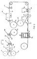
- the carrier film 2 and the transfer film 4 may be payed out from respective reels 6 and 8 and brought together betwen the nip of pressure rollers 10, 12 to form the laminate 14 illustrated sectionally in Figures 2 and 3.
- the laminate may be formed by the application of heat and pressure at the nip of rollers 10, 12, to achieve a releasable surface bond between carrier film 2 and transfer film 4.
- rollers 10, 12 may be heated to a temperature ranging from about 180° to about 350°, and may impose a pressure upon carrier film 2 and transfer film 4 of between 40 psi and 100 psi.
- the temperature would be instantaneously applied at pressure rollers 10, 12 and the respective films 2 and 4 would pass between the nip of the rollers at speeds of up to about 200 feet per minute on a commercial scale.
- the laminate 14 formed by the application of heat and pressure is illustrated in Figure 2.
- the carrier film 2 has been provided with a suitable room temperature, releasable adhesive coating 16, that would retain carrier film 2 and transfer film 4 in contact with each other throughout the following processing, but would release upon either the exertion of mechanical tension, by the stripping of the "skeleton", discussed hereinafter, or by the application of the heat generated by the in-mould hot transfer processing.
- Suitable materials to serve as the releasable adhesive would include certain thermoplastic monomers and polymers, including cellulose esters and ethers and vinyl compounds.
- nitrocellulose may be utilized as the adhesive release coating.
- the coating may be applied in a thickness of less than one mil, and would be disposed as shown in Figure 3.
- the laminate 14 may comprise a combination of an approximately 2 mil thick polyester carrier film, to which a roughly 1 mil thickness transfer film has been "piggy backed".
- a roughly 1 mil thickness transfer film has been "piggy backed".
- a typical printing station 18 which may comprise a printing roller 20 cooperating with an idler roll 22 and an ink supply roller 24 transferring a thin film of ink from a reservoir 26.
- Printing roller 20 would have appropriately disposed thereon the pattern of the desired indicia, so that the desired decoration is disposed on the free surface of transfer film 4.
- a variety of printing apparatus and techniques may be utilized, all known in the art, and printing station 18 is therefore merely illustrative of an apparatus and associated method that may be utilized to place indicia on transfer film 4.
- the present method contemplates the die-cutting and resulting pre-trimming of the individual decorated portions of transfer film 4.
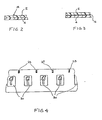
- appropriate indexing indicia or indexing marks 28 may be printed upon the transfer film 4 during the printing operation.
- an indexing mark 28 is disposed in regularly spaced disposition with respect to decorating indicia 30 as shown.
- the decorating indicia may be regularly spaced with respect to each other as well as with respect to decorating indicia 30, to permit the sequential indexing into the mould of the laminate 14, thereby assuring alignment and accurate transfer of indicia 30 during the moulding sequence.
- the accuracy of transfer, as well as that of the formed decoration, is a function of the positioning of the die during the die-cutting operation described hereinafter.
- the importance of the indexing mark 28 can thus be appreciated.
- an alternate printing station is shown, to facilitate the application of sequential, divergent colours, patterns, etc., to form a composite decoration.
- regularly spaced printing stations 32, 34 and 36 are disposed to receive laminate 14.
- Printing stations 32, 34 and 36 carry individual patterns, and/or colours so that colour or pattern blends may be applied in overlying fashion to blend or complement each other.
- the printing inks, etc. applied to the surface of transfer film 4 may be of the variety that dry on contact, so as to avoid “bleeding" of the various colours between adjacent printing stations, in the instance where printing rollers are utilized.
- printing may be applied by means other than pressured application, such as heat printing, screen printing, etc., "bleeding" may pose no problem.
- the printing operation frequently includes the disposition of a metalized coating as a "base" portion of the decoration.
- the decoration may include a border and lettering.
- one or more colours are applied by the techniques described above, with appropriate areas left unprinted, to account for the later application of a metalized layer, to define either or both the border of the decoration and the lettering thereon.
- selective printing of colours may vary to suit the specific effect desired in the decoration, so that the invention is not limited to the disposition of the metalized effect in any specific position. The foregoing is therefore illustrative only.
- the printed laminate 38 is passed through appropriate idler rolls 40, 42 and wound up on a take up roll 44. Thereafter, take up roll 44 is payed out and passes through an appropriate metalizing station 46, illustrated schematically herein, so that the surface of laminate 38 already having printing thereon, is disposed in position to receive the metalized coating. Idler rolls 48 and 50 are illustrated but are optional.
- Metalization may be accomplished by conventional techniques, such as vapour deposition.
- the present invention does not relate to the specific manner in which metalization is accomplished, and therefore the techniques of vapour deposition of metal as known in the art, may be utilized herein, and such techniques are incorporated herein by reference.
- metals may be applied by vapour deposition to form a tightly adherent, continuous coating.
- Such metals would include both precious and nonprecious metals, such as gold, silver, tin, zinc, chromium and aluminium.
- gold may be and is conventionally applied, by deposition to a thickness that may range, for example, up to about 400 Angstroms.
- the exact thickness of the layer is discretionary and may accordingly vary.
- the previous description with regard to printing contemplates a variation in the thickness of the respective colour coatings, with thicknesses on the order of 1 or 2 mils standard.
- the sizing coat may be applied by coating roller station 54, to a thickness that may likewise vary to a few microns.
- the sizing compositions useful in accordance with the present invention include vinyl polymers, acrylic polymers, polyolefins such as polyethylene, and polyurethanes. The sizing coat is applied to ensure the integrity of the metalized coating, through the die-cutting technique, to thereby prevent edge fracture during the die-cut.
- a wash or tie coat of a material such as chlorinated rubber may be applied in a wash coat; however, this is purely optional, and depends upon the conditions and applications to which the decorated heat transfer material is exposed during the in-mould transfer process.
- FIG. 1 After the coating of transfer film 4 is completed in any of the variations described above, the resulting decorated laminate is indexed into position for die-cutting.
- An appropriate die-cutting station 56 is shown, comprising cutting edge 58 adapted to impact transfer film 4, and anvil 60 located adjacent the free surface of carrier film 2.
- cutting edge 58 and anvil 60 are brought together, conventionally by the movement of cutting edge 58, to cause an incision to be formed that passes through the entire thickness of transfer film 4, taking care not to penetrate the underlying adjacent surface of carrier film 2.
- die-cutting station 56 As mentioned earlier, the exact construction and operation of die-cutting station 56 is critical to the accomplishment of the die-cutting operation.
- the die-cutting station 56 as shown in Figure 6, may comprise, in addition to cutting edge 58 and anvil 60, bearing surfaces 62, which serve to limit the motion of cutting edge 58, to ensure that the travel of cutting edge 58 is stopped short of penetration of carrier film 2.
- bearing surfaces 62 The provision of carrier film 2 in the sizes mentioned earlier, requires that the bearing surfaces 62 must be prepared to exacting tolerances, and from materials of critical hardness, to ensure dimensional stability in operation.
- cutting edges 58 must be of critical hardness to ensure sharpness and dimensional stability during high speed, commercial operation, so that complete penetration of transfer film 4 without penetration of carrier film 2, is uniformly achieved.
- cutting edges 58 may be appropriately beveled at acute angles, and may be provided with hardened outer surfaces, by chrome plating, etc. to ensure dimensional stability and uniformity of resulting operation.
- ejector means 67 disposed adjacent cutting edges 58, to ensure that any unwanted portions of transfer film 4 that might be retained by cutting edges 58 after the cutting operation are appropriately removed to avoid clogging and breakdown of die-cutting station 56. This would be appropriate, in the instance where the final transfer material assumes a doughnut shape, and, correspondingly when a central portion of the transfer film 4 must be individually removed. Ejection may be accomplished by air pressure, vacuum, or mechanical means, not shown. The choice of specific ejection means is not critical to the present invention, and may vary within the scope thereof.
- the resulting decorated transfer material is now separated from the unwanted portion of transfer film 4, known as the skeleton.
- Skeleton 64 may be drawn off to an appropriate take off reel 68, as shown schematically in Figure 1, as the die-cut laminate passes an appropriate idler roll 70.
- the die-cut transfer material 66 is retained in position along carrier film 2, which may then be introduced into an appropriate mould assembly labeled 72 and shown schematically in Figure 1, wherein the in-mould transfer to a plastic article simultaneously formed, may take place.
- in-mould decorating is known in the art, and reference is made to U.S. Patents Nos. 4,202,663 and 4,059,471 respectively, to the selected portions thereof, dealing with in-mould decoration.
- the present in-mould decorating process is distinguishable, in that the entire decorated transfer material 66 is permanently bonded to the adjacent surface of the formed article, when the mould is closed, and appropriate heat and pressure are applied.
- the plastic articles may comprise sheets, blocks or the like that are hot stamped into final shape, or appropriate parisons that are placed in a mould cavity and thereafter blown to form hollow articles.
- the carrier film bearing the decorated transfer material may be indexed into the mould cavity, with the printed indicia positioned to lie adjacent the outer surface of the moulded plastics article, whereupon the plastic article and the transfer material and the adjacent surface of the article are forced into pressured contact with each other, at an elevated temperature sufficient to effect a permanent bond therebetween.
- the advantage of the present invention is that a continuous strip of pre-cut decorated heat transfers may be prepared so as to easily index into alignment for application to a plastic article, to facilitate hot transfer to plastic articles in accordance with in-mould decorating techniques, on a continuous basis.
- the present method facilitates the exact positioning of the decorated transfers upon the carrier film, multiple coatings are easily and inexpensively performed, and post-treatment of the decorated plastic articles is eliminated.
Abstract
A carrier film 2 is first bonded to the transfer film 4 from which the hot transfer is prepared, to form a releasable laminate 14. The laminate 14 is then printed with appropriate decorating indicia on the free surface of the transfer film component thereof. Printing may be single-stage or multi-stage, depending upon the indicia desired, and a subsequent metalization of the transfer film surface may be performed.
The fully printed laminate is then indexed into position and die-cut under conditions controlled to ensure full penetration of the transfer film by the die 58, without penetration of the adjacent surface of the carrier film. Thereafter, the unwanted portions of the transfer film are stripped away, leaving the pre-cut decorated transfers, positioned on the carrier film for continuous indexing into position for the in-mould decoration of the plastic article being formed.
The present method eleminates post-treatment of the decorated moulded article.
Description
- The present invention relates to hot transfer materials suitable for application to three dimensional items by the technique of in-mould decoration.
- The decoration of a variety of moulded products, by the application of decorating indicia to the product during the moulding process, i.e. the technique of in-mold decorating, is well known. Thus, such techniques are practiced by feeding into the mould in which the product is to be formed, a continuous strip having regularly spaced thereon, a plurality of identical decorating indicia. Thus, the strip would be indexed into position so that the decoration would be aligned with the intended location on the products, after which the product would be moulded against the decoration and thereafter the strip would be appropriately severed and trimmed to complete the fabrication of the product.
- The standard in-mould decorating technique possesses a variety of drawbacks to its use, particularly in high speed, continuous moulding manufacturing situations. For example, the hot transfer bearing the decorating indicia had to exceed the indicia in size, with the result that the quantities of plastic film utilized per decoration were unnecessarily great. Also, the disposition of additional plastic film on the final product detracted from its appearance.
- Efforts to remove excess plastic film from the decoration could only be directed to post-moulding operations, as pre-cutting or punching of the continuous strip would result in the failure during the moulding process due to malalignment of the decoration with the moulded product. Likewise, attempts to remove excess film from the moulded product frequently result in tearing or other fracturing of the remaining indicia, or damage to the product itself, so that a high rate of rejects would develop.
- The prior art with respect to in-mould decorating, is exemplified by U.S. Patent Nos. 4,059,471 to Haigh, and 4,202,663 to Haigh, deceased et al. These patents speak in passing of in-mould decoration, but concern themselves primarily with the transfer of a dye from a transfer sheet, through a polyolefin film, to a thermoplastic sheet. This is accomplished by the application of heat and pressure, causing the dye to sublime through the film and into the plastic sheet.
- Similarly, the U.S. Patent No. 3,292,209 to Borkmann, and U.S. Patent No. 3,816,207 to Robertson et al., illustrate variant apparatus utilized for the practice of transfer decoration. Borkmann is noted for its effort to develop an apparatus to practice a method disclosed in U.S. Patent No. 3,108,580 to Brandt, wherein labels are indexed into position and a blow-moulded parison, in the semi-molten state, is then inflated thereagainst and heat fused thereto. Borkmann illustrates by its complexity the intricate and critical apparatus that must be utilized in accordance with the prior art, to ensure alignment of the decoration with the product being moulded.
- The criticality and complexity of in-mould decorating techniques, as discussed above, has militated against their use in the preparation of complex decorations, of the type that are now of interest to the packaging field. For example, complex decorations are now desirable for product decoration that may include as many as three or four divergent indicia including photographic facsimiles of a broad range of colours, appropriately trimmed with a metalized layer. The preparation of this type of complex, compound decoration requires the use of techniques such as multiple-stage printing by screen printing techniques and the like, all of which is time consuming and expensive due to the criticality in the alignment of the images of the respective components of the decoration.
- During the course of the development of the present invention, the inventors investigated the use of pre-cutting the hot transfer stock, and determined that such pre-cutting would further complicate any efforts to utilize the film for continuous in-mould decoration. In particular, the pre-cutting of the stock, either in whole or in part, resulted in failure, as the decorated portions of the stock would dislodge and could not be retained in alignment, particularly at the commercial speed of operation, of in-mould decorating procedures. Further investigations revealed that the area of die-cutting of transfer items was well known, but was limited in its application to pressure sensitive labels. Representative prior art patents on die-cutting, comprise U.S. Patent No. 2,391,539 to Avery, and U.S. Patent No. 3,166,186 to Karn. Both patents deal primarily with pressure-adhesive label stock, that is disposed on a peel-away base, and is appropriately die-cut by perforations or full cutting, so that the labels may be easily removed from the base for application to the intended substrate, without preliminarily adhering to themselves or to other objects before use.
- Efforts to apply die-cutting techniques to plastics generally have met with failure. Particularly in the instance where the plastic films are measured in thicknesses of 3 to 10 mils, the tolerance of most die-cutting equipment is such that one cannot guarantee that the cutting edge will strike through the first film and into the second or carrier film, and it is this strike-through that would result in the same difficulty that one would experience if a single film were die-cut by perforation or otherwise. Clearly, then, the die-cutting techniques familiar to the label making art were investigated, and initially found to be unable to meet the rigid tolerances and requirements of the hot transfer industry.
- A need therefore exists for the development of a hot transfer decorated film, that will permit its individual application to a product by a continuous, rather than individual, in-mould decorating technique without the need for complex decoration preparation, and post-treatment of the decorated product.
- In accordance with the present invention, a method for preparing a die-cut hot transfer film useful in continuous in-mould decoration has been developed. The method comprises forming a laminate of a carrier film useful in hot-transfer decorating processes, and a thermoplastic resinous transfer film, which is to serve as the substrate for the decoration. Lamination may be conducted under heat and pressure.
- The decorating indicia are then printed on the laminate, on at least a portion of the free surface of the transfer film. The indicia may be applied in a single printing step, or in multiple steps in the instance of compound or complex indicia, and may be placed in regularly spaced-apart disposition. A plurality of identical indicia may thus be disposed on an elongated strip of the laminate. The printing step may include the initial application of coloured indicia in the same register, followed by an over-plating or application of metalized dress.
- After the application of decorating indicia is complete, the decorated laminate is die-cut in a controlled manner, so that the die fully penetrates the thickness of the transfer film without penetrating the surface of the carrier film.
- After die cutting is complete, the unwanted portion of the transfer film is stripped away, leaving the decorated portions of the transfer film situated on the continuous carrier film, which may then be fed into an appropriate product moulding chamber, and into alignment therein for accurate hot-transfer to a plastic article during the moulding thereof. Thereafter, the carrier film may be reused.
- Preferably, the carrier film may be of any thickness, and may comprise thermoplastic materials useful in hot-transfer processes, such as polyesters, polycarbonates, and cellulose derivates. The film may be transparent or translucent and may be .5 mil in thickness or greater, depending upon the product to which the transfer is to be applied. Suitable thermoplastic resins comprise vinyl polymers, such as polyvinylchloride, modified polyurethanes, acrylic polymers, and polyolefins, such as polyethylene, polypropylene and polystyrene homo - and copolymers.
- Lamination of the carrier film and the transfer film may take place at speeds of up to 200 feet per minute by passage of the two films through the nip of heated rollers. The resulting laminate may then be printed, either by a single or multiple printing sequence, the latter in the instance where a plurality of colours or colour combinations are desired. At the same time, indexing marks may be disposed on the transfer film, to assure alignment for the later die-cutting operation.
- In the instance where multiple colours are applied, followed by a metalized dress, it is preferable to apply a sizing coat after the metalized dress. Sizing coats may be selected from a variety of compositions, including polyurethanes, polyolefins, acrylic and vinyl polymers. In such instance, it is desirable the sizing coat be applied to the entirety of the surface of the transfer film.
- Die-cutting is accomplished by indexing the decorated laminate into appropriate position, with the aid of the indexing marks applied during the printing step. Die hardnesses, bevels and temperatures are carefully controlled to ensure that the cutting edge penetrates fully through the transfer film, but does not penetrate the surface of the carrier film. Among the parameters mentioned is the use of a heated die with beveled cutting edges, that operates against a chilled anvil. A critical aspect of the die-cutting sequence, is the need to continually remove the unwanted portions of the film, known as the "skeleton" both in which portions of the "skeleton" is removed from the laminate by passage thereof through idler rolls and take up of the skeleton thereat.
- The resulting product is then continually indexed into position within appropriate moulds, to complete the in-mould decorating technique. In-mould decoration, per se, is conducted in accordance with known techniques.
- The product emerging from the mould, has placed in perfect alignment thereon, the desired decoration. There is no need for post-treatment of the product, such as trimming etc. of the decoration to remove excess portions of the hot transfer. The resulting decoration possesses improved appearance as it is in greater integration with the moulded article.
- The in-mould decorating operation may be run continuously and at commercially desirable speeds, thereby rendering such techniques economically attractive. The decorated hot-transfer prepared in accordance with the present invention is likewise economical, as it can be prepared with relatively simple equipment and with a reduced number of operations. Thus, the complex printing sequences utilized in the prior art may be reduced and intricate decorations may be applied with one or two sequential printing applications.
- Accordingly, it is a principal object of the present invention to provide a method for the preparation of decorated hot-transfer materials for application in continuous in-mould decorating operations.
- It is a further object of the present invention to provide the method as aforesaid, wherein the decorated hot-transfer materials may be prepared from relatively thin layered plastic materials that are die-cut prior to being hot transferred.
- It is a still further object of the present invention to provide a method as aforesaid that is of simple and economical operation.
- It is a still further object of the present invention to provide a method as aforesaid that eliminates costly, time consuming post-treatment of the decorated, moulded plastic articles.
- Other objects and advantages will become apparent to those skilled in the art from a review of the ensuing description which proceeds with reference to the following illustrative drawings, in which:-
- Figure 1 is a schematic plan view sequentially illustrating the steps of the present method.
- Figure 2 is a sectional view taken through Line 1-1 of Figure 1, showing the initial laminate formed by the present invention.
- Figure 3 is a sectional view similar to Figure 2 showing variant laminate in accordance with the present invention.
- Figure 4 is a top plan view in the area defined by Line 2-2 illustrating the placement of indexing marks in accordance with the present invention.
- Figure 5 is an enlarged schematic sectional view similar to the region defined by Line 2-2 in Figure 1, showing a multiple printing station in accordance with an embodiment of the present invention.
- Figure 6 is an enlarged schematic view taken in the area defined by Line 3-3 of Figure 1 showing a representative die-cutting station in accordance with the present invention.
- Figure 7 is a perspective view taken in the area defined by Line 4-4 of Figure 1, showing the skeleton and resulting at the point of their separation from each other.
- In its broadest aspect, the method of the present invention comprises the preparation of a releasable laminate of a carrier film and a thermoplastic resinous transfer film, the transfer film to serve as the outer surface of a decoration to be hot-transferred to a plastic article during the moulding thereof. The formed laminate is provided with printed indicia on the exposed surface of the transfer film, after which it is die-cut to isolate the decorated portions of the transfer film from those unwanted portions of the transfer film, known as the "skeleton". The skeleton is thereafter peeled away, leaving the decorated portions of the transfer film adhesively bound to the carrier film, which is then indexed into alignment within the mould for the plastic articles, so that continuous in-mould decoration of the formed plastic articles may take place by a hot-transfer technique.
- The carrier films useful in accordance with the present method, comprise those films capable of withstanding repeated use in hot-transfer processes. Thus, the carrier should be capable of successive laminations to the transfer film under heat and pressure, followed by stripping of portions of the transfer film, and subsequent exposure to in-mould hot-transfer of the remaining transfer film to the article to be decorated. Additionally, the carrier film should be capable of undergoing repeated exposure to various printing techniques, including vacuum metalization. Suitable materials include films prepared from the materials selected from the group consisting of amorphous and oriented polyester resins, polycarbonate resins, cellulosic derivatives, including cellulose esters and ethers and their copolymers. In particular, the polyesters may include polyethylene terephthalate; polycarbonates may include acrylonitrile-butadienestyrene resins; and the cellulosic derivates include cellulose acetate, cellulose acetate butyrate, ethyl cellulose and viscose, known as "cellophane". The carrier film may vary in thickness from about .5 mil upwards, and preferably, from about 3 mil upwards. A range of .5 mil to about 7 mil is exemplary. The exact thickness of the carrier film will vary with the processing of the transfer film, and the specific moulding technique and article for which decoration is intended.
- The transfer film comprises a thermoplastic resinous material, selectedfrom the group consisting of vinyl resins, modified polyurethane resins, acrylic homo- and copolymers, polyolefin resins, including substituted and unsubstituted resins, and the like. More specifically, the vinyl resins include polyvinylchloride, polyvinylacetate, polyvinyl alcohol and copolymers thereof; the acrylic polymers include polyacrylates, such as polymethylmethacrylate; polyolefins include polyethylene, polypropylene, polystyrene and the like; and polyurethanes include Bisphenol A-epichlorohydrin derivatives, and the like. The transfer film is preferably transparent, but may be translucent and provided with appropriate colouration, to achieve different visual effects. The transfer film may vary in thickness, from .5 mil upward, in similar fashion to the carrier film, depending upon the plastic article to which the transfer film is to be adhered. A thickness ranging from 1 to 3 mils is exemplary.
- Lamination of the transfer film to the carrier film may be conducted by simple heat and pressure. Thus, for example, and referring now to Figure 1, the
carrier film 2 and thetransfer film 4 may be payed out from respective reels 6 and 8 and brought together betwen the nip ofpressure rollers rollers carrier film 2 andtransfer film 4. For example,rollers carrier film 2 andtransfer film 4 of between 40 psi and 100 psi. The temperature would be instantaneously applied atpressure rollers respective films - Referring now to Figure 3, an
alternate laminate 14 is shown. In this instance, thecarrier film 2 has been provided with a suitable room temperature, releasableadhesive coating 16, that would retaincarrier film 2 andtransfer film 4 in contact with each other throughout the following processing, but would release upon either the exertion of mechanical tension, by the stripping of the "skeleton", discussed hereinafter, or by the application of the heat generated by the in-mould hot transfer processing. Suitable materials to serve as the releasable adhesive would include certain thermoplastic monomers and polymers, including cellulose esters and ethers and vinyl compounds. For example, nitrocellulose may be utilized as the adhesive release coating. The coating may be applied in a thickness of less than one mil, and would be disposed as shown in Figure 3. - In a preferred embodiment of the invention, the laminate 14 may comprise a combination of an approximately 2 mil thick polyester carrier film, to which a roughly 1 mil thickness transfer film has been "piggy backed". Naturally, the foregoing thicknesses are illustrative only, and are not intended to limit the present invention.
- After its formation, the laminate 14 may then be appropriately printed with the desired decorating indicia. Referring to Figure 1, a
typical printing station 18 is illustrated, which may comprise aprinting roller 20 cooperating with anidler roll 22 and an ink supply roller 24 transferring a thin film of ink from areservoir 26. Printingroller 20 would have appropriately disposed thereon the pattern of the desired indicia, so that the desired decoration is disposed on the free surface oftransfer film 4. A variety of printing apparatus and techniques may be utilized, all known in the art, andprinting station 18 is therefore merely illustrative of an apparatus and associated method that may be utilized to place indicia ontransfer film 4. Referring briefly to Figure 4, the present method contemplates the die-cutting and resulting pre-trimming of the individual decorated portions oftransfer film 4. To assist in the accurate operation of the die-cutting step, appropriate indexing indicia or indexing marks 28 may be printed upon thetransfer film 4 during the printing operation. Thus, as shown in Figure 4, anindexing mark 28 is disposed in regularly spaced disposition with respect to decoratingindicia 30 as shown. - Referring further to Figure 4 momentarily, it can be seen that the decorating indicia may be regularly spaced with respect to each other as well as with respect to decorating
indicia 30, to permit the sequential indexing into the mould of the laminate 14, thereby assuring alignment and accurate transfer ofindicia 30 during the moulding sequence. - The accuracy of transfer, as well as that of the formed decoration, is a function of the positioning of the die during the die-cutting operation described hereinafter. The importance of the
indexing mark 28 can thus be appreciated. - Referring now to Figure 5, an alternate printing station is shown, to facilitate the application of sequential, divergent colours, patterns, etc., to form a composite decoration. As illustrated, regularly spaced
printing stations laminate 14.Printing stations transfer film 4 may be of the variety that dry on contact, so as to avoid "bleeding" of the various colours between adjacent printing stations, in the instance where printing rollers are utilized. As printing may be applied by means other than pressured application, such as heat printing, screen printing, etc., "bleeding" may pose no problem. - One of the aspects of multiple colour printing, is that, in accordance with the present invention, a technique known as "reverse printing" must be utilized. That is, in the instance where a substrate is printed with a multiple colour decoration, the sequence of colour application is such that the last-applied colour is that which forms the uppermost portion of the decoration. In the instance where, however, the decoration is applied to the underside of a film, this order must be reversed, so that "reverse printing" must be utilized. Accordingly,
printing station 32 as illustrated would apply the uppermost colour and indicia, withprinting stations - Referring further to Figure 1, the printing operation frequently includes the disposition of a metalized coating as a "base" portion of the decoration. Thus, the decoration may include a border and lettering. Frequently, one or more colours are applied by the techniques described above, with appropriate areas left unprinted, to account for the later application of a metalized layer, to define either or both the border of the decoration and the lettering thereon. Naturally, selective printing of colours may vary to suit the specific effect desired in the decoration, so that the invention is not limited to the disposition of the metalized effect in any specific position. The foregoing is therefore illustrative only.
- Referring again to Figure 1, in the instance where a metalized coating is to be applied, the printed
laminate 38 is passed through appropriate idler rolls 40, 42 and wound up on a take uproll 44. Thereafter, take uproll 44 is payed out and passes through anappropriate metalizing station 46, illustrated schematically herein, so that the surface oflaminate 38 already having printing thereon, is disposed in position to receive the metalized coating. Idler rolls 48 and 50 are illustrated but are optional. - Metalization may be accomplished by conventional techniques, such as vapour deposition. The present invention does not relate to the specific manner in which metalization is accomplished, and therefore the techniques of vapour deposition of metal as known in the art, may be utilized herein, and such techniques are incorporated herein by reference.
- As known in the art, a number of metals may be applied by vapour deposition to form a tightly adherent, continuous coating. Such metals would include both precious and nonprecious metals, such as gold, silver, tin, zinc, chromium and aluminium. For example, aluminium may be and is conventionally applied, by deposition to a thickness that may range, for example, up to about 400 Angstroms. The exact thickness of the layer is discretionary and may accordingly vary. In similar fashion, the previous description with regard to printing, contemplates a variation in the thickness of the respective colour coatings, with thicknesses on the order of 1 or 2 mils standard.
- In the instance where a metalized coating is applied, it is advisable to likewise apply a sizing coating before the resulting
laminate 42 is die-cut. Referring again to Figure 1, the sizing coat may be applied by coatingroller station 54, to a thickness that may likewise vary to a few microns. The sizing compositions useful in accordance with the present invention, include vinyl polymers, acrylic polymers, polyolefins such as polyethylene, and polyurethanes. The sizing coat is applied to ensure the integrity of the metalized coating, through the die-cutting technique, to thereby prevent edge fracture during the die-cut. In the further event that the sizing coat as applied, reduces adhesion of the ultimate decoration, a wash or tie coat of a material such as chlorinated rubber may be applied in a wash coat; however, this is purely optional, and depends upon the conditions and applications to which the decorated heat transfer material is exposed during the in-mould transfer process. - Referring now to Figures 1 and 6, after the coating of
transfer film 4 is completed in any of the variations described above, the resulting decorated laminate is indexed into position for die-cutting. An appropriate die-cuttingstation 56 is shown, comprisingcutting edge 58 adapted to impacttransfer film 4, andanvil 60 located adjacent the free surface ofcarrier film 2. Upon the positioning of the laminate withinstations 56, cuttingedge 58 andanvil 60 are brought together, conventionally by the movement of cuttingedge 58, to cause an incision to be formed that passes through the entire thickness oftransfer film 4, taking care not to penetrate the underlying adjacent surface ofcarrier film 2. - As mentioned earlier, the exact construction and operation of die-cutting
station 56 is critical to the accomplishment of the die-cutting operation. Specifically the die-cuttingstation 56 as shown in Figure 6, may comprise, in addition to cuttingedge 58 andanvil 60, bearing surfaces 62, which serve to limit the motion of cuttingedge 58, to ensure that the travel of cuttingedge 58 is stopped short of penetration ofcarrier film 2. The provision ofcarrier film 2 in the sizes mentioned earlier, requires that the bearing surfaces 62 must be prepared to exacting tolerances, and from materials of critical hardness, to ensure dimensional stability in operation. - In similar fashion, cutting
edges 58 must be of critical hardness to ensure sharpness and dimensional stability during high speed, commercial operation, so that complete penetration oftransfer film 4 without penetration ofcarrier film 2, is uniformly achieved. Thus, for example, cuttingedges 58 may be appropriately beveled at acute angles, and may be provided with hardened outer surfaces, by chrome plating, etc. to ensure dimensional stability and uniformity of resulting operation. - Other features of the die-cutting
stations 56, illustrated in Figure 6, include an ejector means 67, disposedadjacent cutting edges 58, to ensure that any unwanted portions oftransfer film 4 that might be retained by cuttingedges 58 after the cutting operation are appropriately removed to avoid clogging and breakdown of die-cuttingstation 56. This would be appropriate, in the instance where the final transfer material assumes a doughnut shape, and, correspondingly when a central portion of thetransfer film 4 must be individually removed. Ejection may be accomplished by air pressure, vacuum, or mechanical means, not shown. The choice of specific ejection means is not critical to the present invention, and may vary within the scope thereof. - Upon completion of the die-cutting operation, the resulting decorated transfer material is now separated from the unwanted portion of
transfer film 4, known as the skeleton. Referring now to Figure 7, the removal of theskeleton 64, leavingcarrier film 2 bearing complete decoratedtransfer material 66, is illustrated in perspective.Skeleton 64 may be drawn off to an appropriate take offreel 68, as shown schematically in Figure 1, as the die-cut laminate passes anappropriate idler roll 70. Thus, the die-cut transfer material 66 is retained in position alongcarrier film 2, which may then be introduced into an appropriate mould assembly labeled 72 and shown schematically in Figure 1, wherein the in-mould transfer to a plastic article simultaneously formed, may take place. - The technique of in-mould decorating is known in the art, and reference is made to U.S. Patents Nos. 4,202,663 and 4,059,471 respectively, to the selected portions thereof, dealing with in-mould decoration. The present in-mould decorating process is distinguishable, in that the entire decorated
transfer material 66 is permanently bonded to the adjacent surface of the formed article, when the mould is closed, and appropriate heat and pressure are applied. - The in-mould decoration techniques utilized in accordance with the present invention, may vary depending upon the plastic articles and their method of manufacture. Thus, for example, as illustrated in the aforementioned '663 and '471 patents, the plastic articles may comprise sheets, blocks or the like that are hot stamped into final shape, or appropriate parisons that are placed in a mould cavity and thereafter blown to form hollow articles. In each instance, the carrier film bearing the decorated transfer material may be indexed into the mould cavity, with the printed indicia positioned to lie adjacent the outer surface of the moulded plastics article, whereupon the plastic article and the transfer material and the adjacent surface of the article are forced into pressured contact with each other, at an elevated temperature sufficient to effect a permanent bond therebetween. An apparatus suitable for the performance of in-mould decorating, is also disclosed in U.S. Patent No. 3,292,209 to Borkmann, and the disclosure thereof is accordingly incorporated herein by reference as illustrative of any in-mould decorating technique and associated apparatus useful in accordance with the present invention.
- It can therefore be seen that the advantage of the present invention is that a continuous strip of pre-cut decorated heat transfers may be prepared so as to easily index into alignment for application to a plastic article, to facilitate hot transfer to plastic articles in accordance with in-mould decorating techniques, on a continuous basis. As the present method facilitates the exact positioning of the decorated transfers upon the carrier film, multiple coatings are easily and inexpensively performed, and post-treatment of the decorated plastic articles is eliminated.
- This invention may be embodied in other forms or carried out in other ways without departing from the spirit or essential characteristics thereof. The present disclosure is therefore to be considered as in all respects illustrative and not restrictive, the scope of the invention being indicated by the appended claims, and all changes which come within the meaning and range of equivalency are intended to be embraced therein.
Claims (25)
1. A method for preparing a die-cut hot transfer film for use in the continuous in-mould decoration of moulded plastic articles, comprising forming a laminate from a carrier film capable of participating in hot-transfer decorating processes, and a printable thermoplastic transfer film, printing at least one decorating indicia on said laminate, on at least a portion of the free surface of said thermoplastic transfer film, die-cutting said thermoplastic transfer film in a controlled manner to fully penetrate the thickness of said thermoplastic transfer film without penetrating the adjacent surface of said carrier film, and separating the unwanted portions of said thermoplastic transfer film from said carrier film, so that the portions of said thermoplastic transfer film bearing said decorating indicia remain releasably bound to said carrier film wherein the portions of said thermoplastic transfer film bearing said decorating indicia are bound and aligned on said carrier film and thereby adapted to index into exact alignment for accurate transfer to moulded plastic articles by said in-mould decoration.
2. A method according to Claim 1, wherein said carrier film is selected from the group consisting of polyester resin, polycarbonate resins, and cellulosic derivates.
3. A method according to Claim 1, wherein said carrier film is selected from the group consisting of polyethylene terephthalate, acrylonitrile-butadienestyrene resins, cellulose acetate, cellulose acetate butyrate, ethyl cellulose and cellophane.
4. A method according to any of Claims 1 to 3, wherein said carrier film has a thickness of at least .5 mil.
5. A method according to Claim 4, wherein said thickness ranges from about .5 mil to about 7 mil.
6. A method according to any of Claims 1 to 5, wherein said thermoplastic transfer film is selected from the group consisting of vinyl resins, modified polyurethane resins, acrylic homopolymers acrylic copolymers, and polyolefin resins.
7. A method according to any of Claims 1 to 5, wherein said thermoplastic transfer film is selected from the group consisting of polyvinylchloride, polyvinylacetate, polyvinyl alcohol, copolymers thereof; polyacrylates, polymethylmethacrylate, homopolymers and copolymers thereof; polyethylene, polypropylene, polystyrene, homopolymers and copolymers thereof; substituted polyurethanes, and unsubstituted polyurethanes.
8. A method according to any of the preceding Claims, wherein said thermoplastic transfer film is at least .5 mil in thickness.
9. A method according to any of Claims 1 to 7, wherein said thermoplastic transfer film ranges in thickness from about 1 mil to about 3 mils.
10. A method according to any of Claims 1 to 9, wherein a plurality of decorating indicia are printed on said laminate in regularly spaced-apart relationship to each other.
11. A method according to Claim 10, wherein said laminate comprises a continuous strip and wherein an indefinite number of identical decorating indicia are printed thereon.
12. A method according to any of Claims 1 to 11, wherein said printing step includes the printing on said thermoplastic transfer film of at least one indexing mark, in spaced relation to said decorating indicia, to serve as a guide for the alignment of said laminate during said die-cutting step.
13. A method according to claim 12, wherein a plurality of regularly spaced indexing marks are printed on said thermoplastic transfer film, in spaced relation to each other, and to said decorating indicia, so that each of said decorating indicia may be properly aligned for said die-cutting step.
14. A method according to any of Claims 1 to 13, wherein said decorating indicia is printed in a single colour and in a single printing pass.
15. A method according to any of Claims 1 to 13, wherein said decorating indicia is printed in a plurality of different colours.
16. A method according to Claim 15, wherein said different colours are applied in a single printing pass.
17. A method according to Claim 15, wherein said different colours are applied sequentially at regularly spaced printing stations.
18. A method according to Claim 16 or Claim 17, wherein said different colours are applied in reverse fashion with the colour intended to appear outermost being applied first.
19. A method according to Claim 14, further including applying a layer of vaporized metal to at least a portion of said decorating indicia.
20. A method according to Claim 15, further including applying a layer of vaporized metal to at least a portion of said decorating indicia.
21. A method according to Claim 17, further including applying a layer of vaporized metal to at least a portion of said decorating indicia.
22. A method according to any of Claims 19 to 21, wherein, subsequent to the application of said layer of vaporized metal, a sizing coat is applied thereon.
23. A method according to Claim 22, wherein said sizing coat is selected from the group consisting of polyurethane resins, acrylic resins, vinyl resins and polyolefin resins.
24. A method according to Claim 1, wherein said die-cutting is performed by pressing an appropriately configured cutting die against the surface of said laminate defined by said thermoplastic transfer film, while steadying said laminate against a supporting anvil.
25. A method according to Claim 24, wherein said die-cutting is performed under a temperature gradient, with heat applied to said thermoplastic transfer film through said cutting edge, while reduced temperature is applied to said carrier film through said anvil.
Priority Applications (4)
| Application Number | Priority Date | Filing Date | Title |
|---|---|---|---|
| US06/576,605 US4643789A (en) | 1982-07-23 | 1984-02-03 | Method for preparing a decorated insert and continuous insert molding operation |
| US06/674,482 US4650533A (en) | 1982-07-23 | 1984-11-23 | Preparation of hot transfer product for continuous in-mold decoration |
| EP86306555A EP0264498A3 (en) | 1982-07-23 | 1986-08-22 | Method for preparing a decorated insert and continuous insert moulding operation |
| EP86306554A EP0258501A1 (en) | 1982-07-23 | 1986-08-22 | Preparation of hot transfer product for continuous in-mould decoration |
Applications Claiming Priority (3)
| Application Number | Priority Date | Filing Date | Title |
|---|---|---|---|
| US40127582A | 1982-07-23 | 1982-07-23 | |
| EP86306555A EP0264498A3 (en) | 1982-07-23 | 1986-08-22 | Method for preparing a decorated insert and continuous insert moulding operation |
| EP86306554A EP0258501A1 (en) | 1982-07-23 | 1986-08-22 | Preparation of hot transfer product for continuous in-mould decoration |
Publications (1)
| Publication Number | Publication Date |
|---|---|
| EP0258501A1 true EP0258501A1 (en) | 1988-03-09 |
Family
ID=38792010
Family Applications (2)
| Application Number | Title | Priority Date | Filing Date |
|---|---|---|---|
| EP86306555A Withdrawn EP0264498A3 (en) | 1982-07-23 | 1986-08-22 | Method for preparing a decorated insert and continuous insert moulding operation |
| EP86306554A Withdrawn EP0258501A1 (en) | 1982-07-23 | 1986-08-22 | Preparation of hot transfer product for continuous in-mould decoration |
Family Applications Before (1)
| Application Number | Title | Priority Date | Filing Date |
|---|---|---|---|
| EP86306555A Withdrawn EP0264498A3 (en) | 1982-07-23 | 1986-08-22 | Method for preparing a decorated insert and continuous insert moulding operation |
Country Status (2)
| Country | Link |
|---|---|
| US (2) | US4643789A (en) |
| EP (2) | EP0264498A3 (en) |
Cited By (4)
| Publication number | Priority date | Publication date | Assignee | Title |
|---|---|---|---|---|
| EP0264498A2 (en) * | 1982-07-23 | 1988-04-27 | Transfer Print Foils, Inc | Method for preparing a decorated insert and continuous insert moulding operation |
| FR2659901A1 (en) * | 1990-03-22 | 1991-09-27 | Acknin Christian | Method for withdrawing cut-out parts from at least one layer of a sheet material and machine for implementing the method |
| US5443950A (en) * | 1986-04-18 | 1995-08-22 | Advanced Tissue Sciences, Inc. | Three-dimensional cell and tissue culture system |
| CN103522823A (en) * | 2012-07-03 | 2014-01-22 | 锣洋科技股份有限公司 | Method for manufacturing decorative molded article and shaping mold |
Families Citing this family (117)
| Publication number | Priority date | Publication date | Assignee | Title |
|---|---|---|---|---|
| USRE37248E1 (en) | 1986-07-14 | 2001-06-26 | The Dow Chemical Company | Coextruded plastic film label for in-mold labeling |
| US5707697A (en) * | 1987-03-27 | 1998-01-13 | Avery Dennison Corporation | Dry paint transfer product having high DOI automotive paint coat |
| US6835267B1 (en) * | 1987-03-27 | 2004-12-28 | Avery Dennison Corporation | Dry paint transfer process and product |
| YU46540B (en) | 1987-03-27 | 1993-11-16 | Avery International Corp. | LAMINATE WHICH CAN BE HEAT-FORMED FOR THE FORMATION OF A THREE-DIMENSIONALLY FORMED OUTER LAYER ON THE OUTER SURFACE OF A CAR PANEL |
| FR2614576B1 (en) * | 1987-04-29 | 1990-01-19 | Monoplast Sa | PROCESS FOR OBTAINING DECORATED PLASTIC CONTAINERS AND CONTAINERS OBTAINED ACCORDING TO THIS PROCESS |
| FR2615479B1 (en) * | 1987-05-18 | 1989-12-22 | Alsacienne Aluminium | METHOD AND MACHINE FOR CLOSING CONTAINERS, ESPECIALLY JARS AND TRAYS |
| US4902557A (en) * | 1988-01-25 | 1990-02-20 | E. I. Du Pont De Nemours And Company | Thermoplastic polyolefin composite structure |
| US5055346A (en) * | 1988-08-30 | 1991-10-08 | Frank Rohrbacher | Thermoplastic acrylic polymer coated composite structure |
| US4936936A (en) * | 1988-08-30 | 1990-06-26 | E. I. Du Pont De Nemours And Company | Method of making thermoplastic acrylic polymer coated composite structure |
| US5001000A (en) * | 1988-09-26 | 1991-03-19 | E. I. Du Pont De Nemours And Company | Process for forming a composite structure of thermoplastic polymer and sheet molding compound |
| US4959189A (en) * | 1988-09-26 | 1990-09-25 | E. I. Du Pont De Nemours And Company | Process for forming a composite structure of thermoplastic polymer and sheet molding compound |
| US5118372A (en) * | 1988-11-21 | 1992-06-02 | Eastman Kodak Company | Method of forming a protective and decorative sheet material on a substrate |
| US6001208A (en) * | 1989-03-17 | 1999-12-14 | Yoshino Kogyosho Co., Ltd. | Method for in-mold Molding using a label |
| DE4122049A1 (en) * | 1991-07-03 | 1993-01-07 | Gao Ges Automation Org | METHOD FOR INSTALLING A CARRIER ELEMENT |
| US5318660A (en) * | 1992-05-01 | 1994-06-07 | Kensol-Olsenmark, Inc. | Method and apparatus for generating hot stamped single and multi-color images |
| EP0600187A1 (en) * | 1992-10-06 | 1994-06-08 | Decora, Incorporated | Composite for in-mould transfer printing and decoration of plastic or rubber articles, and process for its use |
| US5707472A (en) * | 1992-10-06 | 1998-01-13 | Decora Incorporated | Composite for in-mold transfer printing and process for in-mold printing of molded plastic or rubber articles therewith |
| DE4311200A1 (en) * | 1993-04-05 | 1994-10-06 | Zweckform Buero Prod Gmbh | Decorative labels and processes for their manufacture |
| US5516393A (en) * | 1993-04-29 | 1996-05-14 | Avery Dennison Corporation | Labelling of substrates |
| ATE159209T1 (en) * | 1994-02-22 | 1997-11-15 | Infra Folienkabel Gmbh | METHOD AND DEVICE FOR PRODUCING FOAM DECORATIVE PANELS |
| US5464690A (en) * | 1994-04-04 | 1995-11-07 | Novavision, Inc. | Holographic document and method for forming |
| US5795527A (en) * | 1994-04-29 | 1998-08-18 | Nissha Printing Co., Ltd. | Method of manufacturing decorated article using a transfer material |
| EP0710187B1 (en) * | 1994-05-17 | 2001-09-26 | Technoflex Innovations Limited | The coating of surfaces of articles |
| US5757459A (en) * | 1995-03-03 | 1998-05-26 | Vision-Ease Lens, Inc. | Multifocal optical elements |
| US5599608A (en) * | 1995-06-20 | 1997-02-04 | Green Tokai Co., Ltd. | Method of insert molding plastic parts to provide covered edge surfaces and plastic parts made thereby |
| US5759477A (en) * | 1996-12-13 | 1998-06-02 | Green Tokai Co. Ltd. | Method of making fused film plastic parts |
| US6367361B1 (en) | 1997-07-30 | 2002-04-09 | Ford Motor Company | Method and apparatus for trimming thermoformed films |
| US5951939A (en) * | 1997-07-30 | 1999-09-14 | Ford Motor Company | Method for heating films for thermoforming |
| US5972279A (en) * | 1997-07-30 | 1999-10-26 | Ford Motor Company | Method of transferring a pre-molded film into a mold |
| US5985198A (en) * | 1997-07-30 | 1999-11-16 | Ford Motor Company | Method for molding a film-covered article |
| US6143227A (en) * | 1997-07-30 | 2000-11-07 | Visteon Global Technologies, Inc. | Method for injection molding an article having film covered flanges |
| US6221304B1 (en) | 1997-07-30 | 2001-04-24 | Visteon Global Technologies, Inc. | Method of manufacturing a film coated article |
| US6141870A (en) | 1997-08-04 | 2000-11-07 | Peter K. Trzyna | Method for making electrical device |
| US6294038B1 (en) * | 1998-08-05 | 2001-09-25 | Advanced Label Systems, Inc. | Apparatus and method for applying linerless labels |
| US7369048B2 (en) * | 1999-03-19 | 2008-05-06 | Fusion Graphics, Inc. | RFID systems and graphic image fusion |
| US6544634B1 (en) | 1999-03-19 | 2003-04-08 | Pinnacle Products Group, Ltd. | Graphic image fusion |
| US7927688B2 (en) * | 1999-03-19 | 2011-04-19 | Standard Register Company | Security information and graphic image fusion |
| US6214266B1 (en) | 1999-04-06 | 2001-04-10 | Green Tokai Co., Ltd. | Method for injection molding plastic parts |
| US6497567B1 (en) | 1999-10-04 | 2002-12-24 | Serigraph Inc. | Multi-purpose processing apparatus |
| US6576080B1 (en) * | 1999-10-20 | 2003-06-10 | Xyron, Inc. | Adhesive transfer device |
| SE521876C2 (en) * | 1999-12-22 | 2003-12-16 | Tetra Laval Holdings & Finance | Multi-stage unit for processing a web-shaped packaging material in a food packaging machine |
| US6863854B2 (en) * | 2000-02-25 | 2005-03-08 | General Electric | Insert mold decorating film for thermoplastic resin and methods for making |
| US7077985B2 (en) * | 2000-05-30 | 2006-07-18 | Vision-Ease Lens | Injection molding of lens |
| US7344769B1 (en) | 2000-07-24 | 2008-03-18 | High Voltage Graphics, Inc. | Flocked transfer and article of manufacture including the flocked transfer |
| US7364782B2 (en) * | 2000-07-24 | 2008-04-29 | High Voltage Graphics, Inc. | Flocked transfer and article of manufacture including the application of the transfer by thermoplastic polymer film |
| US20070289688A1 (en) * | 2000-07-24 | 2007-12-20 | High Voltage Graphics, Inc. | Processes for precutting laminated flocked articles |
| US20050258559A1 (en) * | 2000-09-01 | 2005-11-24 | Johansen Loren R | Thermoforming method and apparatus for use in an injection molding machine |
| WO2002020241A1 (en) * | 2000-09-01 | 2002-03-14 | Serigraph Inc. | Thermoforming method and apparatus for use in an injection molding machine |
| CN1191173C (en) * | 2001-07-16 | 2005-03-02 | 太乙印刷企业股份有限公司 | Planography plus screen print technology for IMD hot press and ejection forming |
| WO2003008193A1 (en) | 2001-07-20 | 2003-01-30 | Xyron, Inc. | Substrate processing apparatus |
| US20030041962A1 (en) * | 2001-09-05 | 2003-03-06 | John R. Johnson | Digitally printed products and process |
| US20050107231A1 (en) * | 2003-02-10 | 2005-05-19 | Productivity California, Inc. | Method for printing images and text on a plant container |
| US20050102897A1 (en) * | 2003-02-10 | 2005-05-19 | Productivity California, Inc. | Plant container and method for making a plant container |
| US7293592B1 (en) | 2003-03-03 | 2007-11-13 | George Schmitt & Co., Inc | Forming and applying linerless labels |
| US7097796B2 (en) * | 2003-05-13 | 2006-08-29 | Bayer Materialscience Llc | Method of preparing a decorated molded article |
| EP1631857B1 (en) * | 2003-06-06 | 2007-03-07 | Sipix Imaging, Inc. | In mold manufacture of an object with embedded display panel |
| EP2955567A1 (en) | 2003-09-09 | 2015-12-16 | Insight Equity A.P.X., LP | Photochromic polyurethane laminate |
| US7858001B2 (en) * | 2003-09-09 | 2010-12-28 | Insight Equity A.P.X., L.P. | Photochromic lens |
| CA2541821A1 (en) * | 2003-10-08 | 2005-04-21 | High Voltage Graphics, Inc. | Processes for precutting laminated flocked articles |
| FI20031634A (en) * | 2003-11-11 | 2005-05-12 | Jari Ruuttu | Process for manufacturing molded plastic products and integrated processing method |
| US20050106362A1 (en) * | 2003-11-13 | 2005-05-19 | Gene Kim | Energetic beam markable sheet |
| KR101426946B1 (en) * | 2003-11-28 | 2014-08-06 | 다이니폰 인사츠 가부시키가이샤 | Decorating sheet, decorated resin molded article and method for production thereof |
| US7465485B2 (en) * | 2003-12-23 | 2008-12-16 | High Voltage Graphics, Inc. | Process for dimensionalizing flocked articles or wear, wash and abrasion resistant flocked articles |
| DE102004002591B4 (en) * | 2004-01-16 | 2016-03-03 | Robert Bosch Gmbh | fire alarm |
| US7393576B2 (en) | 2004-01-16 | 2008-07-01 | High Voltage Graphics, Inc. | Process for printing and molding a flocked article |
| US20050196594A1 (en) * | 2004-03-02 | 2005-09-08 | Illinois Tool Works, Inc. | In-mold label composition and process |
| EP1732707B1 (en) | 2004-03-19 | 2015-04-22 | Commonwealth Scientific and Industrial Research Organisation | Activation method |
| US20060062970A1 (en) | 2004-04-19 | 2006-03-23 | Martin James N | Embossed headliner and method of making same |
| GB2420740A (en) * | 2004-11-19 | 2006-06-07 | Peter Geoffrey Alan Morrish | Printable laminated article |
| EP1828335B1 (en) | 2005-01-21 | 2010-03-10 | Commonwealth Scientific And Industrial Research Organisation | Activation method using modifying agent |
| US8002935B2 (en) | 2005-03-04 | 2011-08-23 | Insight Equity A.P.X., L.P. | Forming method for polymeric laminated wafers comprising different film materials |
| GB2423958A (en) * | 2005-03-09 | 2006-09-13 | Peter Geoffrey Morrish | Printable laminate |
| TWI252150B (en) * | 2005-03-22 | 2006-04-01 | Speed Tech Corp | In mold decoration fabrication of injection molding |
| US20070019049A1 (en) * | 2005-07-22 | 2007-01-25 | National Pen Corp. | Insert molded print product on demand |
| WO2007016341A2 (en) * | 2005-07-28 | 2007-02-08 | High Voltage Graphics, Inc. | Flocked articles incorporating a porous film |
| GB2435472A (en) * | 2006-02-23 | 2007-08-29 | 3M Innovative Properties Co | Method for forming an article having a decorative surface |
| EP1839952B1 (en) * | 2006-03-28 | 2011-10-19 | Autoliv Development AB | Emblem of automobile part and method of manufacturing the same |
| WO2008101115A1 (en) | 2007-02-14 | 2008-08-21 | High Voltage Graphics, Inc. | Sublimation dye printed textile |
| US8094027B2 (en) | 2007-12-19 | 2012-01-10 | Abbott Laboratories | Method for molding an object containing a radio frequency identification tag |
| US20090179342A1 (en) * | 2008-01-12 | 2009-07-16 | Pedro Jorge Pinto Oliveira Araujo | Process for In-molding Labels onto Plastic During a Hybrid Thermoforming-injection Molding Process |
| US20090239025A1 (en) * | 2008-03-04 | 2009-09-24 | High Voltage Graphics, Inc. | Flocked articles having a woven graphic design insert and methods of making the same |
| US9073383B2 (en) * | 2008-06-06 | 2015-07-07 | Illinois Tool Works Inc. | Heat transfer label variable data indicator and method of making same |
| US20100143669A1 (en) * | 2008-12-04 | 2010-06-10 | High Voltage Graphics, Inc. | Sublimation dye printed textile design having metallic appearance and article of manufacture thereof |
| WO2010094044A1 (en) * | 2009-02-16 | 2010-08-19 | High Voltage Graphics, Inc. | Flocked stretchable design or transfer including thermoplastic film and method for making the same |
| WO2010118429A1 (en) * | 2009-04-10 | 2010-10-14 | High Voltage Graphics, Inc. | Flocked article having woven insert and method for making the same |
| US20110214082A1 (en) * | 2010-02-28 | 2011-09-01 | Osterhout Group, Inc. | Projection triggering through an external marker in an augmented reality eyepiece |
| US9091851B2 (en) | 2010-02-28 | 2015-07-28 | Microsoft Technology Licensing, Llc | Light control in head mounted displays |
| US10180572B2 (en) | 2010-02-28 | 2019-01-15 | Microsoft Technology Licensing, Llc | AR glasses with event and user action control of external applications |
| US9182596B2 (en) | 2010-02-28 | 2015-11-10 | Microsoft Technology Licensing, Llc | See-through near-eye display glasses with the optical assembly including absorptive polarizers or anti-reflective coatings to reduce stray light |
| US9366862B2 (en) | 2010-02-28 | 2016-06-14 | Microsoft Technology Licensing, Llc | System and method for delivering content to a group of see-through near eye display eyepieces |
| US9229227B2 (en) | 2010-02-28 | 2016-01-05 | Microsoft Technology Licensing, Llc | See-through near-eye display glasses with a light transmissive wedge shaped illumination system |
| US9341843B2 (en) | 2010-02-28 | 2016-05-17 | Microsoft Technology Licensing, Llc | See-through near-eye display glasses with a small scale image source |
| CN102906623A (en) * | 2010-02-28 | 2013-01-30 | 奥斯特豪特集团有限公司 | Local advertising content on an interactive head-mounted eyepiece |
| US9129295B2 (en) | 2010-02-28 | 2015-09-08 | Microsoft Technology Licensing, Llc | See-through near-eye display glasses with a fast response photochromic film system for quick transition from dark to clear |
| US9759917B2 (en) | 2010-02-28 | 2017-09-12 | Microsoft Technology Licensing, Llc | AR glasses with event and sensor triggered AR eyepiece interface to external devices |
| US8467133B2 (en) | 2010-02-28 | 2013-06-18 | Osterhout Group, Inc. | See-through display with an optical assembly including a wedge-shaped illumination system |
| US8472120B2 (en) | 2010-02-28 | 2013-06-25 | Osterhout Group, Inc. | See-through near-eye display glasses with a small scale image source |
| US20120249797A1 (en) | 2010-02-28 | 2012-10-04 | Osterhout Group, Inc. | Head-worn adaptive display |
| US9134534B2 (en) | 2010-02-28 | 2015-09-15 | Microsoft Technology Licensing, Llc | See-through near-eye display glasses including a modular image source |
| US9128281B2 (en) | 2010-09-14 | 2015-09-08 | Microsoft Technology Licensing, Llc | Eyepiece with uniformly illuminated reflective display |
| US9285589B2 (en) | 2010-02-28 | 2016-03-15 | Microsoft Technology Licensing, Llc | AR glasses with event and sensor triggered control of AR eyepiece applications |
| US20150309316A1 (en) | 2011-04-06 | 2015-10-29 | Microsoft Technology Licensing, Llc | Ar glasses with predictive control of external device based on event input |
| US8488246B2 (en) | 2010-02-28 | 2013-07-16 | Osterhout Group, Inc. | See-through near-eye display glasses including a curved polarizing film in the image source, a partially reflective, partially transmitting optical element and an optically flat film |
| US9097891B2 (en) | 2010-02-28 | 2015-08-04 | Microsoft Technology Licensing, Llc | See-through near-eye display glasses including an auto-brightness control for the display brightness based on the brightness in the environment |
| US9097890B2 (en) | 2010-02-28 | 2015-08-04 | Microsoft Technology Licensing, Llc | Grating in a light transmissive illumination system for see-through near-eye display glasses |
| US8477425B2 (en) | 2010-02-28 | 2013-07-02 | Osterhout Group, Inc. | See-through near-eye display glasses including a partially reflective, partially transmitting optical element |
| US8482859B2 (en) | 2010-02-28 | 2013-07-09 | Osterhout Group, Inc. | See-through near-eye display glasses wherein image light is transmitted to and reflected from an optically flat film |
| US9223134B2 (en) | 2010-02-28 | 2015-12-29 | Microsoft Technology Licensing, Llc | Optical imperfections in a light transmissive illumination system for see-through near-eye display glasses |
| US10083634B2 (en) | 2010-11-15 | 2018-09-25 | Taylor Communications, Inc. | In-mold labeled article and method |
| US20120193021A1 (en) * | 2011-02-02 | 2012-08-02 | Stanley Botten | Structures and methods for making sports shafts suitable for graphics application |
| US20130011624A1 (en) * | 2011-07-07 | 2013-01-10 | Nissha Printing Co., Ltd. | In-Mold Decorated Fibrous Molded Object and Method for Manufacturing the Same |
| US20140098170A1 (en) * | 2012-10-09 | 2014-04-10 | William M Karszes | Systems and methods for creating multi-dimensional images on demand for the creation of customized products |
| CN104837645A (en) | 2012-10-12 | 2015-08-12 | 高压制图公司 | Flexible heat sealable decorative articles and method for making same |
| US10501245B2 (en) * | 2013-12-11 | 2019-12-10 | Carmine Montemarano | Lid for a disposable beverage container including graphic images and method of fabricating same |
| CN107073760B (en) * | 2014-05-30 | 2020-09-29 | 专一展览公司 | Thermosetting in-mold finishing film |
| US20170246782A2 (en) * | 2015-03-12 | 2017-08-31 | Ford Global Technologies, Llc | Method of molding a composite sheet |
| DE102015109597A1 (en) * | 2015-06-16 | 2017-01-05 | Bond-Laminates Gmbh | Process for producing a plastic molding, plastic molding and molding tool |
Citations (5)
| Publication number | Priority date | Publication date | Assignee | Title |
|---|---|---|---|---|
| US4089722A (en) * | 1976-09-23 | 1978-05-16 | Holoubek Studios, Inc. | Method of affixing heat transferrable indicia to a fabric surface |
| GB2013574A (en) * | 1978-01-05 | 1979-08-15 | Costa D D De | Dry Transfer Sheet |
| US4202663A (en) * | 1972-09-25 | 1980-05-13 | Haigh John M | Method of dye absorption into the surface of plastic |
| US4369157A (en) * | 1977-04-11 | 1983-01-18 | Dri-Print Foils, Inc. | Method of automatically decorating articles as they are in-mold formed automatically |
| US4386123A (en) * | 1981-09-28 | 1983-05-31 | Coburn Jr Joseph W | Article of manufacture and methods of manufacturing |
Family Cites Families (29)
| Publication number | Priority date | Publication date | Assignee | Title |
|---|---|---|---|---|
| US2391539A (en) * | 1942-07-13 | 1945-12-25 | Avery Ray Stanton | Method of making pressure sensitive labels |
| US2523234A (en) * | 1942-09-23 | 1950-09-19 | Rado Leopold | Process for the printing of plastics |
| US2627485A (en) * | 1949-08-06 | 1953-02-03 | Arthur L Smith | Process of applying inked indicia to a rubber article using an image reproducing film |
| US2817619A (en) * | 1954-07-02 | 1957-12-24 | Glidden Co | Process for preparing polyester-faced bodies |
| US3108850A (en) * | 1960-11-23 | 1963-10-29 | American Can Co | Labeling of blown plastic containers |
| US3166186A (en) * | 1962-06-25 | 1965-01-19 | Andrew B Karn | Pressure sensitive labels, label stocks, and methods for manufacturing the same |
| US3292209A (en) * | 1963-12-10 | 1966-12-20 | American Can Co | Labeling apparatus |
| GB1302284A (en) * | 1969-06-12 | 1973-01-04 | E Langecker | |
| US3816207A (en) * | 1972-08-10 | 1974-06-11 | Ethyl Corp | Method and apparatus for hot stamping cylindrical articles |
| US3886020A (en) * | 1972-08-17 | 1975-05-27 | Anchor Hocking Corp | Method of applying decals to surfaces of complex curvature |
| US4059471A (en) * | 1972-09-25 | 1977-11-22 | Haigh John M | Transfer dyeing of plastic surfaces which may be combined with lamination or molding procedures |
| CA1069380A (en) * | 1976-10-29 | 1980-01-08 | Allan R. Prittie | Printing and die-cutting apparatus |
| US4153496A (en) * | 1978-02-27 | 1979-05-08 | Markem Corporation | Label manufacturing apparatus |
| US4263077A (en) * | 1978-05-12 | 1981-04-21 | Avery International Corporation | In-press transfer painting of hardboard |
| US4181551A (en) * | 1978-06-12 | 1980-01-01 | Allied Chemical Corporation | Method of producing stamped plastic articles |
| US4213926A (en) * | 1978-07-28 | 1980-07-22 | Taisei Kensetsu Kabushiki Kaisha | Method for making a decorative plate used in a building |
| JPS5559942A (en) * | 1978-10-30 | 1980-05-06 | Toyoda Gosei Co Ltd | Method of decorating and molding surface of plastic article |
| AT367352B (en) * | 1979-01-12 | 1982-06-25 | Barta Franz Kg | DECAL FOR APPLICATION OF DECORS OR SIGNS USING VAPOR AND PRINT ON ITEMS OF GLASS, CERAMIC OR THE LIKE. |
| US4235657A (en) * | 1979-02-12 | 1980-11-25 | Kimberly Clark Corporation | Melt transfer web |
| US4263027A (en) * | 1979-03-12 | 1981-04-21 | Joseph Varnas | Multi-vortical separator |
| US4418033A (en) * | 1979-06-20 | 1983-11-29 | Yoshiharu Hatakeyama | Method of manufacturing a decorated forming article |
| US4359358A (en) * | 1980-03-17 | 1982-11-16 | Graphic Resources, Inc. | In-store coupon and methods |
| JPS5738123A (en) * | 1980-08-20 | 1982-03-02 | Nissha Printing Co Ltd | Preparation of foil decoration moldings |
| JPS5791246A (en) * | 1980-11-29 | 1982-06-07 | Yoshida Kogyo Kk <Ykk> | Method and apparatus for molding cubic part automatically and decoratively |
| JPS57195683A (en) * | 1981-05-28 | 1982-12-01 | Toppan Printing Co Ltd | Manufacture of molded product having pattern on its surface |
| US4568403A (en) * | 1982-03-17 | 1986-02-04 | Miller Products, Inc. | Method of making laminated member |
| US4643789A (en) * | 1982-07-23 | 1987-02-17 | Transfer Print Foils | Method for preparing a decorated insert and continuous insert molding operation |
| FR2574019A1 (en) * | 1984-04-20 | 1986-06-06 | Delteil Denis | Production of a container or cover, decorated inside and outside, by assembling, during thermoforming, thin heat-meltable film whose amalgamation imparts the desired rigidity to the assembly, in a single operation |
| JPS6178686A (en) * | 1984-09-26 | 1986-04-22 | Dainippon Printing Co Ltd | Printing film for vacuum forming |
-
1984
- 1984-02-03 US US06/576,605 patent/US4643789A/en not_active Expired - Lifetime
- 1984-11-23 US US06/674,482 patent/US4650533A/en not_active Expired - Lifetime
-
1986
- 1986-08-22 EP EP86306555A patent/EP0264498A3/en not_active Withdrawn
- 1986-08-22 EP EP86306554A patent/EP0258501A1/en not_active Withdrawn
Patent Citations (5)
| Publication number | Priority date | Publication date | Assignee | Title |
|---|---|---|---|---|
| US4202663A (en) * | 1972-09-25 | 1980-05-13 | Haigh John M | Method of dye absorption into the surface of plastic |
| US4089722A (en) * | 1976-09-23 | 1978-05-16 | Holoubek Studios, Inc. | Method of affixing heat transferrable indicia to a fabric surface |
| US4369157A (en) * | 1977-04-11 | 1983-01-18 | Dri-Print Foils, Inc. | Method of automatically decorating articles as they are in-mold formed automatically |
| GB2013574A (en) * | 1978-01-05 | 1979-08-15 | Costa D D De | Dry Transfer Sheet |
| US4386123A (en) * | 1981-09-28 | 1983-05-31 | Coburn Jr Joseph W | Article of manufacture and methods of manufacturing |
Cited By (5)
| Publication number | Priority date | Publication date | Assignee | Title |
|---|---|---|---|---|
| EP0264498A2 (en) * | 1982-07-23 | 1988-04-27 | Transfer Print Foils, Inc | Method for preparing a decorated insert and continuous insert moulding operation |
| EP0264498A3 (en) * | 1982-07-23 | 1989-06-14 | Transfer Print Foils, Inc | Method for preparing a decorated insert and continuous insert moulding operation |
| US5443950A (en) * | 1986-04-18 | 1995-08-22 | Advanced Tissue Sciences, Inc. | Three-dimensional cell and tissue culture system |
| FR2659901A1 (en) * | 1990-03-22 | 1991-09-27 | Acknin Christian | Method for withdrawing cut-out parts from at least one layer of a sheet material and machine for implementing the method |
| CN103522823A (en) * | 2012-07-03 | 2014-01-22 | 锣洋科技股份有限公司 | Method for manufacturing decorative molded article and shaping mold |
Also Published As
| Publication number | Publication date |
|---|---|
| US4650533A (en) | 1987-03-17 |
| US4643789A (en) | 1987-02-17 |
| EP0264498A2 (en) | 1988-04-27 |
| EP0264498A3 (en) | 1989-06-14 |
Similar Documents
| Publication | Publication Date | Title |
|---|---|---|
| US4650533A (en) | Preparation of hot transfer product for continuous in-mold decoration | |
| US4386123A (en) | Article of manufacture and methods of manufacturing | |
| EP0587178B1 (en) | In-mold label with coupon | |
| EP0606699A1 (en) | Metallized labels | |
| JP4194672B2 (en) | Acrylic insert molding and its manufacturing method, multilayer film for insert molding | |
| US4720315A (en) | Method for preparing a selectively decorated resin film | |
| EP0102205A2 (en) | Apparatus for manufacturing foil shapes having a cast plastic cap | |
| JP2006187938A (en) | Resin molded product and its manufacturing method | |
| JP3862814B2 (en) | Thin-film acrylic insert molding and its manufacturing method | |
| JP3762887B2 (en) | Method for producing hairline decorative molded product | |
| KR100884829B1 (en) | The fabricating method for the metal and hologram emblem of expressing multi-colors | |
| JPS63170099A (en) | Method of decorating three-dimensional molded product | |
| JPS63170100A (en) | Manufacture of heat transfer film used for continuous type in-mold decorating | |
| JP2844218B2 (en) | Decoration method with rose letters | |
| US5622582A (en) | Method of forming printed composite material | |
| JP2004351722A (en) | Partially vapor-deposited transfer foil and its manufacturing method | |
| JP4136133B2 (en) | Insert film | |
| JP4167554B2 (en) | In-mold transfer molding method and dent removal film | |
| JPH02223438A (en) | Molded object with decorated front and rear, manufacture of same molded object and sheet for decoration | |
| JP3003934B1 (en) | Manufacturing method of insert material and insert molded product | |
| JP3272101B2 (en) | In-mold label with coupon | |
| US11872789B2 (en) | Decorative film for insert molding, method for manufacturing decorative film for insert molding, and method for manufacturing resin molded product | |
| EP3698962B1 (en) | Lettering film | |
| JP4247050B2 (en) | Continuous film and in-mold transfer molding method | |
| JP2000263590A (en) | Production of decorative molding |
Legal Events
| Date | Code | Title | Description |
|---|---|---|---|
| PUAI | Public reference made under article 153(3) epc to a published international application that has entered the european phase |
Free format text: ORIGINAL CODE: 0009012 |
|
| AK | Designated contracting states |
Kind code of ref document: A1 Designated state(s): AT BE CH DE FR GB IT LI LU NL SE |
|
| 17P | Request for examination filed |
Effective date: 19880909 |
|
| STAA | Information on the status of an ep patent application or granted ep patent |
Free format text: STATUS: THE APPLICATION IS DEEMED TO BE WITHDRAWN |
|
| 18D | Application deemed to be withdrawn |
Effective date: 19900301 |
|
| RIN1 | Information on inventor provided before grant (corrected) |
Inventor name: GREENMAN, JOSEPH Inventor name: PARKER, HARRY A. |