EP0262429A2 - Data processor having a high speed data transfer function - Google Patents
Data processor having a high speed data transfer function Download PDFInfo
- Publication number
- EP0262429A2 EP0262429A2 EP87112744A EP87112744A EP0262429A2 EP 0262429 A2 EP0262429 A2 EP 0262429A2 EP 87112744 A EP87112744 A EP 87112744A EP 87112744 A EP87112744 A EP 87112744A EP 0262429 A2 EP0262429 A2 EP 0262429A2
- Authority
- EP
- European Patent Office
- Prior art keywords
- data
- signal
- transfer
- busy
- serial
- Prior art date
- Legal status (The legal status is an assumption and is not a legal conclusion. Google has not performed a legal analysis and makes no representation as to the accuracy of the status listed.)
- Granted
Links
Images


Classifications
-
- G—PHYSICS
- G06—COMPUTING; CALCULATING OR COUNTING
- G06F—ELECTRIC DIGITAL DATA PROCESSING
- G06F13/00—Interconnection of, or transfer of information or other signals between, memories, input/output devices or central processing units
- G06F13/38—Information transfer, e.g. on bus
- G06F13/42—Bus transfer protocol, e.g. handshake; Synchronisation
- G06F13/4247—Bus transfer protocol, e.g. handshake; Synchronisation on a daisy chain bus
- G06F13/4256—Bus transfer protocol, e.g. handshake; Synchronisation on a daisy chain bus using a clocked protocol
-
- G—PHYSICS
- G06—COMPUTING; CALCULATING OR COUNTING
- G06F—ELECTRIC DIGITAL DATA PROCESSING
- G06F15/00—Digital computers in general; Data processing equipment in general
- G06F15/16—Combinations of two or more digital computers each having at least an arithmetic unit, a program unit and a register, e.g. for a simultaneous processing of several programs
- G06F15/163—Interprocessor communication
- G06F15/17—Interprocessor communication using an input/output type connection, e.g. channel, I/O port
Definitions
- the present invention relates to a data processor, and in particular, to a serial data processor having a clock line and a data line, which executes the transmission/reception of data in synchronism with a serial clock.
- LSI semiconductor processors
- one data (for example, of 8 bits) is transferred continuously in the form of serial bits, but an interval period is required between transfers of each unit data to confirm the reception. If the receiver is not capable of receiving data, it is necessary to wait until the receiver becomes receivable.
- a BUSY signal is supplied to the transmitter. The transmitter checks the BUSY signal and discriminates whether or not the data can be transferred so as to generate a transfer start signal when it becomes possible to transfer. This start signal is needed in order to control a serial clock necessary for a serial data transfer or clear a counter counting the bit number of data to be transferred.
- the conventional serial data processor has been so designated that after checking whether or not the processor which is as a receiver is in a busy condition, a start signal for the next data transfer is not generated until the busy condition is dissolved.
- a useless waiting time for checking the busy condition is increased, lowering the efficiency of the whole data processing.
- the serial data processor it is the simplest way to check the busy condition by an interrupt processing.
- a data processor which does not have a funciton of the multi-interrupt control if another interrupt is generated during the checking time, the processing of the second interrupt must be waited until it is returned to the main program after dissolution of the busy condition.
- a serial data processor which is as a receiver, after having received a serial data, outputs a BUSY signal so as to inform another serial data processor which is as a transmitter that the receiving device is in the course of data processing. Therefore, it has been required to execute special programs for setting and dissolving the BUSY signal. Such programs are mostly started by an interrupt processing. Since it must take a long time to execute an interrupt processing for the BUSY control, a long period is required until the data processor returns to the proper main program processing after reception of the serial data. Further, as it is necessary to prepare the programs for setting and dissolving the BUSY condition, there has been a problem that the program area for the proper data processing is limited by the programs for controlling the BUSY. Particularly, in the case that a large amount of data are transferred in serial, one round of the processing consisting of a 1-bite serial data transfer and a data processing needs a long time. Thus, there has been also a drawback that the transfer speed is lowered.
- an object of the present invention is to provide a data processor having a data transfer function, which has overcome at least one of the above mentioned drawbacks of the conventional ones.
- Another object of the present invention is to provide a data processor which can execute a serial data transfer at a high speed.
- Still another object of the present invention is to provide a data processor which can be used as a transmitter and which can wait the dissolution of the busy condition of a receiving device while allowing processing of an interrupt generated in the busy condition.
- a further object of the present invention is to provide a data processor which can be used as a receiver and which can generate a busy signal without requiring special program, so that the data processor can process an interrupt generated in the busy condition.
- a data processor comprising a data processing means for supplying a predetermined length of data to be transferred and generating a transfer start signal, a data transferring means receiving the predetermined length of data to be transferred from the data processing means for transferring the same data through a data transferring terminal, means for detecting a transfer inhibit signal from an external, means receiving the transfer start signal from the data processing means for temporarily holding the same transfer start signal, and transfer control means associated to the data transferring means for causing the data transferring means to stop the transfer of data during the period the transfer inhibiting signal is active and allowing the data transferring unit to start the transfer of data at least when the transfer inhibiting signal becomes inactive after the transfer start signal is generated.
- the data transferring means includes a shift register having a parallel input coupled through an internal data bus to the data processing means to receive a predetermined length of parallel data from the data processing means, the shift register having a serial output coupled to the data transfer terminal, and a clock control means for generating a serial clock to a clock transferring terminal and to the shift register so as to cause the data held in the shift register to be outputted from the serial output of the shift register in synchronism with the serial clock.
- the transfer inhibit signal detecting means includes a busy detector responsive to a busy signal from a data receiving device for generating a busy detection signal
- the transfer start signal holding means includes a flip-flop adapted to be set by the transfer start signal so as to generate a start memory signal
- the transfer control means includes a transfer start controller receiving the busy detection signal and the start memory signal for generating, when the busy detection signal is inactive and the start memory signal is active, a start trigger signal to the clock control means and the flip-flop, so that the clock control means causes the shift register to output the serial data and the flip-flop is reset.
- the busy detector is connected at its input to a busy signal terminal independent of the data transfer terminal.
- the busy detector is connected at its input to the data transfer terminal, and the serial output of the shift register is connected to an input of an buffer circuit whose output is connected to the data transfer terminal.
- the output of the buffer circuit assumes either a high impedance condition or a low level condition in response to the input so that when the data transfer terminal is connected to a pulled-up data transfer line, the data transfer line is selectively brought either into a low level or into a high level in accordance with the output condition of the buffer circuit.
- a data processor comprising a data receiving means for receiving a predetermined length of data through a data transfer terminal and generating a reception end signal when the predetermined length of data has been received, a data processing means coupled to the data receiving means for processing the received data and generating a transfer acknowledge signal when the processing of the received data has been completed, and means receiving the reception end signal and the transfer acknowledge signal for generating a transfer inhibit signal after the reception end signal has been generated until the transfer acknowledge signal has been generated.
- the data receiving means includes a shift register having a serial input coupled to the data transfer terminal and a parallel output coupled through an internal data bus to the data processing means, and a clock control means receiving a serial clock through a clock transferring terminal for causing the transfer data to be serially inputted to the shift register in synchronism with the received clock.
- the transfer inhibit signal generating means includes a flip-flop having a set input connected to receive the reception end signal and a reset input connected to receive the transfer acknowledge signal.
- the flip-flop also has an inverted output generating a busy signal which is rendered active when the reception end signal becomes active and is rendered inactive when the transfer acknowledge signal becomes active.
- the inverted output of the flip-flop is connected to a busy signal terminals independent of the data transfer terminal.
- the clock control means is adapted to generate a synchronizing clock after the predetermined length of data has been received
- the processor further includes a synchronizing flip-flop receiving the inverted output of the busy signal generating flip-flop and the synchronizing clock for generating a synchronous busy signal starting from a first synchronizing clock after the inverted output of the busy signal generating flip-flop is rendered active, and a buffer circuit having an input connected to receive the synchronous busy signal and an output connected to the data transfer terminal.
- the output of the buffer circuit assumes a high impedance condition when the synchronous busy signal is inactive and a low level condition when the synchronous busy signal is active, so that when the data transfer terminal is connected to a pulled-up data transfer line, the data transfer line is selectively brought either into a low level or into a high level in accordance with the output condition of the buffer circuit.
- Figure 1 is a block diagram of a data transfer system including a serial data processor of the first embodiment in accordance with the present invention, which includes a first serial data processor 100 which is used as a transmitter and a second serial data processor 310 which is used as a receiver.
- the first serial data processor 100 comprises a shift register 301, a serial clock controller 302, a busy detector 170, a start controller 171, a start memory flip-flop 172, an internal data bus 305, a data processing unit 306, a serial data output terminal 330, a serial clock terminal 332 and a BUSY input terminal 333, which are coupled as shown.
- the shift register 301, the serial data output terminal 330, the serial clock terminal 332, the BUSY input terminal 333, the internal data bus 305 and the data processing unit 306 may be identical with corresponding ones of conventional devices, and therefore, detailed description thereon will be omitted.
- the start memory flip-flop 172 is used to store that the start instruction has been dispatched.
- the flip-flop 172 is set by a transfer start signal 350 generated by the data processing unit 306 at the time of execution of a transfer start instruction so as to output a high level of start memory signal 154.
- the BUSY detector 170 receives a BUSY signal from the BUSY input terminal 333 and detect the condition of the busy signal. If the input signal is at a low level, i.e., in a busy condition, a high level signal is outputted as a BUSY detection signal 155. On the other hand, if the input signal is at a high level, i.e., not in the busy condition, a low level signal is outputted.
- the start controller 171 operates to inhibit the start of the serial transfer at the time of the busy condition.
- the start controller 171 receives the BUSY detection signal 155 and the start memory signal 154.
- the start controller 171 outputs a one shot pulse as a start trigger signal 153 to the clock controller 302.
- the start controller 171 outputs the start trigger signal 153 just after the start memory signal 154 has become a high level.
- the serial clock controller 302 does not generate a serial clock. Namely, the start of the serial data transfer is reserved.
- the start memory signal 154 is at a high level and then, the BUSY detector 170 outputs a low level signal 153 after detecting the dissolution of the busy condition, the start controller 171 outputs the start trigger signal 153 so as to dissolve the start reservation.
- the start memory flip-flop 172 is cleared by the same signal so that the start memory signal 154 becomes at a low level.
- the serial clock controller 302 after receiving the start trigger signal 153, outputs the serial clock to the serial clock terminal 332 and the shift register 301. Then, the shift register 301 initiates the shift operation.
- the second serial data processor 310 which is as a receiver may be of the same construction as that of the first serial data processor except that the second one has a BUSY signal generator 314. Therefore, circuits, lines, signals and terminals similar to corresponding ones of the first data processor 100 are given the Reference Numerals which are obtained by adding 10 to the Reference Numerals given to the corresponding ones of the first data processor 100. Explanation on the similar ones of the second data processor 310 will be omitted.
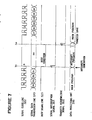
- FIG. 1 is a timing chart illustrating the synchronous relation between a serial data on the serial data line 320, a serial clock on the serial clock line 322, a BUSY signal on the BUSY signal line 323.
- a transfer operation of the 8-bit data from the first serial data processor 100 to the second serial data processor 310 is carried out by serially transmitting each bit of the data to be transferred in synchronism with the clock falling of t1, t3, t5 ... t15 and receiving them in serial in synchronism with the clock rising of t2, t4 ... t16.
- the second serial data processor 310 after having received the 8-bit serial data, generates a serial interrupt at a timing of t16. Then, the data processing unit 316 reads out the content of the shift register 311 through the internal data bus 315 so as to execute the required data processing.
- the BUSY signal generator 314 outputs, by an interrupt processing, a low level signal on the BUSY signal line 323 at a timing t17 so as to inform the first serial data processor 100 of the busy condition.
- the first serial data processor 100 which is as the transmitter detects the busy condition by means of the BUSY detector 170.
- the BUSY detector 170 detects the condition of the BUSY signal inputted from the BUSY input terminal 333 at the timing t17. If it is in a busy condition, the BUSY detector 170 turns the BUSY detection signal 155 to a high level.
- the data processing unit 306, having completed the processing for the next serial data (for example, setting the data to be next transferred to the shift register) in an interrupt mode, dispatches the transfer start instruction at a timing of t18 in the same interrupt mode in order to carry out the next serial data transfer, and then outputs the transfer start signal 350. This operation is executed independently of the BUSY detection. Thereafter, the data processing unit 306 returns from the serial interrupt program to the main program, so as to execute its proper data processing.
- the start memory flip-flop 172 is set by the transfer start signal 350, so that the start memory signal 154 is brought into a high level.
- the start controller 171 detects the transfer start instruction when the start memory signal 154 at a high level is inputted. But, during a period until t19, the start trigger signal 153 is not outputted because the high level of the BUSY detection signal 155 is not outputted. Namely, while the second serial data processor 310 is outputting the BUSY signal, the start trigger signal 153 is not outputted, and therefore, the serial clock controller 302 cannot generate the serial clock. Thus, in this condition, the initiation of the serial transfer operation is reserved.
- the second serial data processor 310 which is as the receiver completes the data processing and dissolves the busy condition so that the BUSY signal line 323 is turned to a high level from a low level, the BUSY detection signal 155 is turned to a low level.
- the one-shot start trigger signal 153 is outputted.
- the serial clock controller 302 After the start controller 171 outputs the start trigger signal 153, the serial clock controller 302 generates the serial clock.
- the start memory flip-flop stores that there has been a transfer start instruction of the serial data. Therefore, the data processing unit can immediately return to the main program from the serial interrupt program without waiting while the BUSY signal is being outputted, so as to execute the proper data processing.
- FIG 3 is a block diagram showing a second embodiment of a serial data processor including a first serial data processor 200 which is used as a transmitter and a second serial data processor 210 which is used as a receiver.
- the BUSY signal line is omitted and the BUSY signal is transferred by using the serial data transfer line.
- the first and second data processors are connected each other by means of only two signal lines (data line and clock line).
- This embodiment is different from the first embodiment in a construction that the busy condition of the reciever is transmitted to the transmitter through the serial data input/output terminals. Therefore, circuits, lines, signals and terminals, similar to those shown in Figure 1 are given the same Reference Numerals.
- the first serial data processor 200 comprises a shift register 301, a serial clock controller 302, a BUSY detector 170, a start controller 171, a start memory flip-flop 172, an internal data bus 305, a data processing unit 306, a shift register output buffer 281, a serial data input/output terminal 235 and a serial clock terminal 332, which are coupled as shown.
- the shift register 301, the start controller 171, the start memory flip-flop 172, the internal data bus 305, the data processing unit 306 and the serial clock terminal are identical with those of the first embodiment shown in Figure 1, and so, detailed description will be omitted.
- the shift register 301 outputs a serial data through the shift register output buffer 281 to the serial data input/output terminal 235.
- the shift register output buffer 281 operates to maintain its output at a high impedance when the output of the shift register 301 is "1", and to output a low level signal when the output of the shift register 301 is "0".
- the serial data transmission/reception line 224 is pulled up to a certain supply voltage by a pull-up resistor 280. If the shift register 301 outputs "1", the output of the shift register output buffer 281 becomes a high impedance, but, the serial data transmission/reception line 224 is turned to a high level by the pull-up resister 280.
- the output of the shift register 301 is controlled so as to maintain a high level after completion of the 8-bit serial data transfer.
- the BUSY detector 170 detects the BUSY signal on the serial data transmission/reception line 224 through the serial data input/output terminal 235.
- the second serial data processor 210 comprises a shift register 311, a serial clock controller 312, a BUSY output circuit 314, an internal data bus 315, a data processing unit 316, a BUSY output buffer 292, a serial data input/output terminal 245 and a serial clock terminal 342.
- the shift register 311, the serial clock controller 312, the BUSY output circuit 314, the internal data bus 315, the data processing unit 316 and the serial clock terminal 342 are identical with those shown in Figure 1, and so, detailed explanation will be omitted.
- the output of the BUSY output circuit 314 is transmitted, through the BUSY output buffer 292 and the serial data input/output terminal 245, and also through the serial data transmission/reception line 224 to the first serial data processor 200.
- the BUSY output buffer 292 is adapted to bring its output to a high impedance when the output of the BUSY output circuit 314 is "1", and to output a low level signal when the output of the BUSY output circuit 314 is "0".
- the shift register output buffer 281 has a high output impedance.
- the serial data transmission/reception line 224 is pulled up to a high level by the pull-up resistor 280. But, if the BUSY output circuit 314 of the second serial data processor 210 outputs a low level signal through the BUSY output buffer 292, the serial data transmission/reception line 224 is turned to a low level, so that the BUSY detector 170 of the shift serial data processor 200 detects a low level signal through the serial data input/output terminal 235.
- FIG. 4 is a timing chart illustrating the synchronous relation between a serial data on the serial data transmission/reception line 224, a serial clock on the serial clock line 322 and the BUSY signal on the serial data transmission/reception line 224.
- the 8-bit data shift operation from the first serial data processor 200 to the second serial data processor 210 is made in a similar manner to that of Figure 1, and therefore, detailed description will be omitted. But, the output of the shift register 301 is turned to a high level at a timing t17 after completion of the 8-bit serial data transfer, so as to prepare to receive the BUSY signal from the receiver.
- the serial data processor 210 having received the 8-bit serial data, generates a serial interrupt at a timing t16. Then, the data processing unit 316 reads out the content of the shift register 311 through the internal data bus 315 so as to execute the required data processing.
- the BUSY signal generator 314 outputs, by an interrupt processing, a low level signal on the serial data transmission/reception line 224 through the BUSY output buffer 292 at a timing t17 so as to inform the first serial data processor 200 of the busy condition.
- the first serial data processor 200 which is used as the transmitter detects the busy condition by means of the BUSY detector 170. Namely, the first serial data processor 200 detects the BUSY signal inputted from the BUSY input terminal 333 and turns the BUSY detection signal 155 to a high level.
- the data processing unit 306 having completed the processing for the next serial data, writes the next data to be transferred on the shift register 311 at a timing t18. As a result, the transfer start signal 350 is generated regardless of the BUSY. Thereafter, the data processing unit 306 returns from the serial interrupt program to the main program so as to execute the proper data processing.
- the start memory flip-flop 172 is set by the transfer start signal 350 so that the start memory signal 154 is turned to a high level.
- the start controller 171 detects that the transfer start instruction has been dispatched when the start controller 171 receives the start memory signal 154 at a high level. But, since the BUSY detection signal 155 is at a high level during a period to a timing t19, the start controller 171 does not output the start trigger signal 153. Namely, the start trigger signal 153 is not outputted while the second serial data processor 210 is outputting the BUSY signal. Thus, since the serial clock controller 302 does not generate a serial clock, the initiation of the serial transfer operation is reserved.
- the busy condition is dissolved at a timing t19. Then, the serial data transmission/reception line 224 is turned from a low level to a high level, so that the BUSY detection signal 155 is turned to a low level.
- the start memory signal 154 is at a high level, there are satisfied the two conditions, i.e., non-busy condition of the second serial data processor and the start instruction execution. As a result, the start trigger signal 153 is outputted.
- the serial clock controller 302 generates a serial clock to initiate the shift opertion of the next 8-bit shift register 301.
- the start memory flip-flop 172 is cleared by the start trigger signal 153, so that the start memory signal 154 is turned to a low level.
- the above mentioned serial data processors including a function of the start signal reservation during the busy condition, can immediately return to the main program from the serial interrupt program without waiting while the receiver device is outputting the BUSY signal, so as to restart the proper data processing.
- the data processing capacity is greatly increased.
- FIG. 5 is a timing chart showing each data processing operation of the above mentioned serial data processor and a conventional serial data processor.
- the main program execution time occupies 80 microseconds in the total of 140 microseconds, the data processing efficiency being 57 %.
- the serial data processor according to the present invention, after the serial data processing even during a peirod of 40 microseconds until initiation of the next serial data transfer, the proper data processing can be executed. Therefore, the main program execution time occupies 120 microseconds in the total of 140 microseconds, the data processing efficiency being 86 % which means 1.5 times as compared with the conventional one.
- the serial data processor according to the present invention can return from the serial interrupt program to the main program. Therefore, it is possible to execute the processing of the other interrupt generated in the busy condition. Thus, particularly in the data processor not capable of multi-interrupt, the response time of the interrupt is remarkably reduced. Also, in the case of the application in a real time processing, a great effect can be obtained.
- the processor according to the present invention can be realized by adding a much less number of hardware such as a BUSY signal detector, a start memory flip-flop and a start reservation circuit. Therefore, there can be obtained a great effect when the present invention is applied as a serial data processor.
- the present invention can be applied to a busy processing in a parallel data transfer.
- Figure 6 is a block diagram of a third embodiment of transmission/reception system composed of a pair of serial data processors, including a first serial data processing device 300 which is used as a master and a second serial data processing device 110 which is used as a slave.
- the first serial data processing unit 300 which is used as a master comprises a shift register 301 for data transmission/reception, a serial clock transmitter 302, a BUSY signal input buffer 303 and a data processing unit 306, all of them being coupled one another by means of an internal bus 305.
- the shift register 301 is a register of 8-bit construction which executes a shift operation for data input/output in sychronism with the falling edge of a serial clock 352.
- the output of the shift register 301 is outputted through a serial data output terminal 330 to a serial data transmission line 320.
- the data processing unit 306 controls the processing operation of the whole serial data processing device 300.
- the data processing unit 306 executes the writing operation of the transmission data to the shift register 301 and the reading operation of the input buffer 303, both through the internal data bus 305. Further, when the start instruction is executed, the data processing unit 306 outputs the transfer start signal 350. Moreover, the data processing unit 306 starts the interrupt by a serial interrupt signal 351 so as to execute the interrupt processing.
- the serial clock controller 302 When the transfer start signal 350 is inputted, the serial clock controller 302 generates the above mentioned serial clock 352 which is outputted to a serial clock terminal and also as a shift clock 353 of the shift register 301. When eight serial clocks 352 are outputted, the supply of the serial clock 352 is stopped so as to stop the serial transfer, and the serial interrupt signal 351 is generated. At the time of no transfer, a high level signal is outputted to a serial clock line 322.
- a BUSY input terminal 333 is connected to a BUSY signal line 323.
- the input buffer 303 is adapted to output the condition of the BUSY input terminal 333 to the internal data bus 305, and which is turned on when the data processing unit 306 executes a BUSY signal read instruction.
- the second serial data processing device 110 comprises a shift register 311, a serial clock receiver 312, a BUSY flip-flop 180, an internal data bus 315, a data processing unit 316, serial data input terminal 341, a serial clock terminal 342 and a BUSY output terminal 344.
- the shift register 311, the internal data bus 315, the data processing unit 316, the serial data input terminal 341, the serial clock terminal 342 and the BUSY output terminal 344 may be identical with those of the device 300 which is a master, and so, detailed description will be omitted.
- the BUSY flip-flop 180 operates to receive a serial interrupt signal 361 at a set input terminal and a transfer acknowledge signal 360 at a reset input terminal, respectively, and outputs a BUSY signal 364 at its inverted output .
- the BUSY flip-flop 180 is set to output a low level signal to the BUSY output terminal 344.
- the BUSY flip-flop 180 is cleared to output a high level signal to the BUSY output terminal 344.
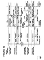
- FIG. 7 is a timing chart showing a synchronous relation between a serial data on the serial data line 320, a serial clock on the serial clock line 322 and a BUSY signal on the BUSY signal line 323.
- the data is transmitted 1-bit by 1-bit in synchronism with the clock.
- the data is received in synchronism with the rising of the clock by the second serial data processing device 110.
- the second serial data processing device 110 having received the 8-bit serial data, generates the serial interrupt signal 361 at a timing t11.
- the BUSY flip-flop 180 being set at the timing t11, outputs a low level signal on the BUSY signal line 323, so as to inform the first serial data processing device 300 of the busy condition.
- a data processing unit 316 reads out the content of the shift register 311 by an interrupt processing and carries out the necessary data processing, so as to execute the transfer start or acknowledge instruction for receiving the next serial data at a timing t12.
- the BUSY flip-flop 180 being cleared at the timing t12, outputs a high level signal on the BUSY signal line 323 so as to inform the first serial data processing device 300 that the busy condition is dissolved.
- the first serial data processing unit 300 which carries out at any time the sampling of the BUSY signal line 323, confirms the dissolution of the busy condition of the second serial data processing device 110, so as to initiate the next serial data transfer.
- the busy condition is automatically set after having received the 8-bit serial data transfer, and the busy condition is dissolved by designation of the transfer start or acknowledge for the next serial data reception.
- the busy condition is not necessary at all to prepare a special program for the BUSY control.
- FIG 8 is a block diagram of fourth embodiment of a serial data processor according to the present invention.
- a first serial data processing device 400 which is used as a transmitter (master) and a second serial data processing device 410 which is used as a receiver (slave).
- the fourth embodiment is for showing a serial data processor which can execute a BUSY signal transfer through a serial data line.
- This embodiment is different from the third one in the construction that the busy condition of the receiver is transmitted to the receiver through the serial data input/output terminal.
- the first serial data processing device 400 is composed of a shift register 301, a serial clock controller 202, an input buffer 303, a BUSY detector 283, an internal data bus 305, a data processing unit 306, a shift regiseter output buffer 282, a serial data input/output terminal 235 and a serial clock terminal 332.
- the shift register 301, the input buffer 303, the internal data bus 305, the data processing unit 306 and the serial clock terminal 332 may be identical with those of the Figure 6, and so, detailed description will be omitted.
- the shift register 301 outputs a serial data through the shift register output buffer 282 to the serial data input/output terminal 235.
- the output of the shift register 301 is maintained at a high level after having transferred an 8-bit serial data.
- the shift register output buffer 282 is of the open drain output type which operates to bring its output to a high impendance when the output of the shift register 301 is "1", and to output a low level signal when the output of the shift register 301 is "0".
- the serial data transmission/reception line 224 is pulled up to a certain supply voltge by means of a pull-up resistor 290.
- the BUSY detector 283 detects the BUSY signal 364 on the serial data transmission/reception line 224 through the serial data input/output terminal 235. When the BUSY detector 283 detects a high level signal which indicates dissolution of the busy condition, the BUSY detector 283 outputs a clock stop signal 257.
- the serial clock controller 302 of Figure 8 is differenct from the serial clock transmitter 302 shown in Figure 6 in the point that the supply of the serial clock 352 to the serial clock terminal 332 continues even after generation of the serial interrupt signal 351, and the generation of the serial clock 352 is stopped by the clock stop signal 257.
- the second serial data processing unit 410 is composed of a shift register 311, a serial clock controller 212, a BUSY flip-flop 180, a synchronizing flip-flop 271, an internal data bus 315, a data processing unit 316, a BUSY output buffer 214, a serial data input/output terminal 245 and a serial clock terminal 342.
- the shift register 311, the internal data bus 315, the data processing device 316, the serial clock terminal 342 and the BUSY flip-flop 180 are identical with those of Figure 6, and so, detailed description will be omitted.
- the serial clock controller 312 further includes a function to output a BUSY synchronizing clock 266.
- the BUSY synchronizing clock 266 is composed of a 9th clock and succeeding clocks of the serial clock 352.
- the synchronizing flip-flop 271 operates to received a BUSY signal 364 and output a synchronous BUSY signal 265 in synchronism with the falling edge of the BUSY synchronizing clock 266.
- the BUSY output buffer 214 is of the open drain output type which operates to assume a high impedance output condition when the output of the synchronizing flip-flop 271 is "1", and to output a low level signal on the serial data transmission/reception line 224 when the output of the synchronizing flip-flop 271 is "0".
- the condition of the serial data input/output terminal 235 of the first serial data processing device 200 becomes a high impedance, while the serial data transmission/reception line 224 is turned to a high level by a pull-up resistor 290.
- the second serial data processing device 210 outputs a low level signal through the BUSY output buffer 214, the serial data transmission/reception line 224 is turned to a low level, which can be detected by the BUSY detector 283.
- FIG. 9 is a timing chart showing a synchronous relation between a serial data and a BUSY signal on the serial data transmission/reception line 224 and a serial clock on the serial clock line 322.
- the 8-bit data transfer operation from the first serial data processing device 400 to the second serial data processing device 410 is made in the same way as that of Figure 6, and so, detailed description will be omitted.
- the output of the shift register 301 is turned to a high level at a timing t22 after completion of the 8-bit serial data transfer, so that a BUSY signal can be received from the receiver.
- the second serial data processing device 410 having received the 8-bit serial data, generates a serial interrupt signal 361 at a timing t21.
- the BUSY flip-flop 180 is set at a timing 11 so as to output a low level signal.
- the synchronizing flip-flop 271 outputs a low level signal to the serial data transmission/reception line 224 in synchronism with the falling timing t22 of the BUSY synchronizing clock 266 so as to inform the first serial data processing device 400 of the busy condition.
- the data processing device 316 reads out the content of the shift register 311 by the interrupt processing, to carry out a necessary data processing, and then generates the transfer start or transfer acknowledge signal at a timing t23 for receiving the next serial data.
- the BUSY flip-flop 180 being cleared at a timing t21, outputs a high level signal.
- the synchronizing flip-flop 271 outputs a high level signal to the serial data transmission line 224 in synchronism with the falling timing t24 of the BUSY synchronizing clock 266, so as to inform the first serial data processing device 400 that the busy condition is dissolved.
- the first serial data processing device 400 carries out the sampling of the busy condition on the serial data transmission/reception line 224 by the BUSY detector 283 after the serial data is transferred, and initiates the next serial data transfer after having confirmed dissolution of the busy condition of the serial data processing device 210.
- the above mentioned serial data processor includes a function capable of executing the setting of the busy condition automatically when the 8-bit serial data transfer is completed, and the dissolution of the busy condition by the serial transfer start operation. Therefore, after the serial transfer is started for the next serial data reception, it is possible to return immediately from the serial interrupt program to the main program so as to restart the proper data processing, without executing the dissolution of the busy signal by means of a program. Thus, the data processing capacity can be greatly improved.
- Figure 10 is a timing chart illustrating respective data processing operations of the serial data processor according to the present invention and the conventional serial data processor.
- the interrupt processing time after the transfer is 90 microseconds, resulting in 170 microseconds in total.
- the interrupt processing time 90 microseconds consists of the setting of the busy condition of 20 microseconds, the proper received data processing of 50 microseconds, and the dissolution of the busy condition of 20 microseconds.
- the interrupt processing after transfer is 90 microseconds which consists of the next transfer processing of 40 microseconds and the waiting time of 50 microseconds for dissolution of the busy condition.
- the serial data processor takes 80 microseconds as the conventional one to execute the 8-bit serial data transfer.
- the interrupt processing time after transfer is 50 microseconds, resulting in 130 microseconds in total.
- the interrupt processing time 50 microseconds consists of 50 microseconds for executing the received data processing since the programs for setting and dissolving the busy condition are no more necessary.
- the interrupt processing after the transfer takes 50 microseconds consisting of the next transfer data processing of 40 microseconds and the waiting time of 10 microseconds for dissolution of the busy condition.
- the interrupt processing time will be described, Conventionally, the interrupt processing has taken 90 microseconds. According to the present invention, it takes only 50 microseconds which is for the received data processing since a processing time 40 microseconds for setting and dissolving the busy condition can be cut off. Thus, the interrupt processing time can be reduced to almost a half as compared with that of the conventional data processor.
- the main program processing time has occupied conventionally 80 microseconds of the 8-bit serial data transfer in the total of 170 microseconds, resultant processing efficiency being 47 %.
- a processing time 40 microseconds for setting and dissolving the busy condition is not necessary, so that during the period of 40 microseconds the main program can be executed. Therefore, the main program processing time results in 120 microseconds by adding the 40 microseconds to 80 microseconds for transferring the 8-bit serial data.
- the obtained processing efficiency is increased to 67 %, which means that 1.5 times of the data processing can be carried out as compared with the conventional one.
- serial data transfer speed will be described.
- One round of the serial data processing time which consists of the 8-bit serial data transfer time and the interrupt processing time has been conventionally 170 microseconds. According to the present invention, it takes only 130 microseconds, resultant speed of one round serial data transfer being increased to 1.3 times as compared with the conventional one. Thus, particularly in the case that a large amount of serial data are transferred, a great effect can be expected.
- serial data processing device which is used as a transmitter can return to the main program earlier by 40 microseconds, as a result of reduced time in the interrupt processing of the serial data processing device which is used as a receiver.
- the response speed to the interrupt is remarkably improved. In particular, if it is applied to the real time processing, a great effect can be expected.
- the BUSY signal output circuit can be realized with an extremely small amount of hardware, there can be obtained such advantages as simplification of the design and reduction of the cost.
- the present invention can be applied to the BUSY control for a parallel processing.
Abstract
Description
- The present invention relates to a data processor, and in particular, to a serial data processor having a clock line and a data line, which executes the transmission/reception of data in synchronism with a serial clock.
- As means for transferring data between a plurality of semiconductor processors (called "LSI" hereinafter) there are a method using a data bus of 8 bits or more parallel lines and a serial transfer method transferring the data in series bit by bit. Since the latter method requires a less number of signal lines for connecting LSIs one another, it is largely used as a simple data transfer means between LSIs.
- In the serial data transfer, one data (for example, of 8 bits) is transferred continuously in the form of serial bits, but an interval period is required between transfers of each unit data to confirm the reception. If the receiver is not capable of receiving data, it is necessary to wait until the receiver becomes receivable. Conventionally, in the case of not receivable, a BUSY signal is supplied to the transmitter. The transmitter checks the BUSY signal and discriminates whether or not the data can be transferred so as to generate a transfer start signal when it becomes possible to transfer. This start signal is needed in order to control a serial clock necessary for a serial data transfer or clear a counter counting the bit number of data to be transferred.
- However, the conventional serial data processor has been so designated that after checking whether or not the processor which is as a receiver is in a busy condition, a start signal for the next data transfer is not generated until the busy condition is dissolved. Thus, in the case that the busy condition extends for a long time, a useless waiting time for checking the busy condition is increased, lowering the efficiency of the whole data processing. Specifically, in the serial data processor it is the simplest way to check the busy condition by an interrupt processing. However, in a data processor which does not have a funciton of the multi-interrupt control, if another interrupt is generated during the checking time, the processing of the second interrupt must be waited until it is returned to the main program after dissolution of the busy condition. Thus, there has been a problem that it takes extremely long time to response to the interrupt. Further, it is necessary to prepare a program for maintaining the data processor in a waiting condition until the busy condition is dissolved, thereby limiting the program area for the proper data processing.
- On the other hand, a serial data processor which is as a receiver, after having received a serial data, outputs a BUSY signal so as to inform another serial data processor which is as a transmitter that the receiving device is in the course of data processing. Therefore, it has been required to execute special programs for setting and dissolving the BUSY signal. Such programs are mostly started by an interrupt processing. Since it must take a long time to execute an interrupt processing for the BUSY control, a long period is required until the data processor returns to the proper main program processing after reception of the serial data. Further, as it is necessary to prepare the programs for setting and dissolving the BUSY condition, there has been a problem that the program area for the proper data processing is limited by the programs for controlling the BUSY. Particularly, in the case that a large amount of data are transferred in serial, one round of the processing consisting of a 1-bite serial data transfer and a data processing needs a long time. Thus, there has been also a drawback that the transfer speed is lowered.
- Accordingly, it is an object of the present invention is to provide a data processor having a data transfer function, which has overcome at least one of the above mentioned drawbacks of the conventional ones.
- Another object of the present invention is to provide a data processor which can execute a serial data transfer at a high speed.
- Still another object of the present invention is to provide a data processor which can be used as a transmitter and which can wait the dissolution of the busy condition of a receiving device while allowing processing of an interrupt generated in the busy condition.
- A further object of the present invention is to provide a data processor which can be used as a receiver and which can generate a busy signal without requiring special program, so that the data processor can process an interrupt generated in the busy condition.
- In order to achieve the above and other objects of the present invention, there is provided in accordance with one aspect of the present invention a data processor comprising a data processing means for supplying a predetermined length of data to be transferred and generating a transfer start signal, a data transferring means receiving the predetermined length of data to be transferred from the data processing means for transferring the same data through a data transferring terminal, means for detecting a transfer inhibit signal from an external, means receiving the transfer start signal from the data processing means for temporarily holding the same transfer start signal, and transfer control means associated to the data transferring means for causing the data transferring means to stop the transfer of data during the period the transfer inhibiting signal is active and allowing the data transferring unit to start the transfer of data at least when the transfer inhibiting signal becomes inactive after the transfer start signal is generated.
- Preferably, the data transferring means includes a shift register having a parallel input coupled through an internal data bus to the data processing means to receive a predetermined length of parallel data from the data processing means, the shift register having a serial output coupled to the data transfer terminal, and a clock control means for generating a serial clock to a clock transferring terminal and to the shift register so as to cause the data held in the shift register to be outputted from the serial output of the shift register in synchronism with the serial clock.
- Further, the transfer inhibit signal detecting means includes a busy detector responsive to a busy signal from a data receiving device for generating a busy detection signal, and the transfer start signal holding means includes a flip-flop adapted to be set by the transfer start signal so as to generate a start memory signal. In addition, the transfer control means includes a transfer start controller receiving the busy detection signal and the start memory signal for generating, when the busy detection signal is inactive and the start memory signal is active, a start trigger signal to the clock control means and the flip-flop, so that the clock control means causes the shift register to output the serial data and the flip-flop is reset.
- In one embodiment, the busy detector is connected at its input to a busy signal terminal independent of the data transfer terminal.
- In another embodiment, the busy detector is connected at its input to the data transfer terminal, and the serial output of the shift register is connected to an input of an buffer circuit whose output is connected to the data transfer terminal. The output of the buffer circuit assumes either a high impedance condition or a low level condition in response to the input so that when the data transfer terminal is connected to a pulled-up data transfer line, the data transfer line is selectively brought either into a low level or into a high level in accordance with the output condition of the buffer circuit.
- In accordance with another aspect of the present invention there is provided a data processor comprising a data receiving means for receiving a predetermined length of data through a data transfer terminal and generating a reception end signal when the predetermined length of data has been received, a data processing means coupled to the data receiving means for processing the received data and generating a transfer acknowledge signal when the processing of the received data has been completed, and means receiving the reception end signal and the transfer acknowledge signal for generating a transfer inhibit signal after the reception end signal has been generated until the transfer acknowledge signal has been generated.
- Preferably, the data receiving means includes a shift register having a serial input coupled to the data transfer terminal and a parallel output coupled through an internal data bus to the data processing means, and a clock control means receiving a serial clock through a clock transferring terminal for causing the transfer data to be serially inputted to the shift register in synchronism with the received clock.
- Furthermore, the transfer inhibit signal generating means includes a flip-flop having a set input connected to receive the reception end signal and a reset input connected to receive the transfer acknowledge signal. The flip-flop also has an inverted output generating a busy signal which is rendered active when the reception end signal becomes active and is rendered inactive when the transfer acknowledge signal becomes active.
- In one embodiment, the inverted output of the flip-flop is connected to a busy signal terminals independent of the data transfer terminal.
- In another embodiment, the clock control means is adapted to generate a synchronizing clock after the predetermined length of data has been received, and the processor further includes a synchronizing flip-flop receiving the inverted output of the busy signal generating flip-flop and the synchronizing clock for generating a synchronous busy signal starting from a first synchronizing clock after the inverted output of the busy signal generating flip-flop is rendered active, and a buffer circuit having an input connected to receive the synchronous busy signal and an output connected to the data transfer terminal. The output of the buffer circuit assumes a high impedance condition when the synchronous busy signal is inactive and a low level condition when the synchronous busy signal is active, so that when the data transfer terminal is connected to a pulled-up data transfer line, the data transfer line is selectively brought either into a low level or into a high level in accordance with the output condition of the buffer circuit.
- The above and other objects, features and advantages of the present invention will be apparent from the following description of preferred embodiments of the invention with reference to the accompanying drawings.
-
- Figure 1 is a block diagram of a serial data processor of a first embodiment in accordance with the present invention;
- Figure 2 is a timing chart of a serial data transmitted/received by the serial data processor of the first embodiment;
- Figure 3 is a block diagram showing a serial data processor of a second embodiment in accordance with the present invention;
- Figure 4 is a timing chart of a serial data transmitted/received by the serial data processor of the second embodiment;
- Figure 5 is a timing chart showing the comparison of the respective data processing operations of the serial data processor according to the present invention and the conventional serial data processor;
- Figure 6 is a block diagram showing a serial data processor of a third embodiment in accordance with the present invention;
- Figure 7 is a timing chart of a serial data transmitted/received by the serial data processor of the third embodiment;
- Figure 8 is a block diagram showing a serial data processor of a fourth embodiment according to the present invention;
- Figure 9 is a timing chart of a serial data transferred/received by the serial data processor of the fourth embodiment; and
- Figure 10 is a timing chart illustrating the comparison of respective data processing operations by the serial data processor according to the present invention and the conventional serial data processor.
- Figure 1 is a block diagram of a data transfer system including a serial data processor of the first embodiment in accordance with the present invention, which includes a first serial data processor 100 which is used as a transmitter and a second
serial data processor 310 which is used as a receiver. - First, the explanation will be made on the first serial data processor 100 which is as the transmitter. The first serial data processor 100 comprises a
shift register 301, aserial clock controller 302, abusy detector 170, a start controller 171, a start memory flip-flop 172, aninternal data bus 305, adata processing unit 306, a serialdata output terminal 330, aserial clock terminal 332 and aBUSY input terminal 333, which are coupled as shown. Among them, since theshift register 301, the serialdata output terminal 330, theserial clock terminal 332, theBUSY input terminal 333, theinternal data bus 305 and thedata processing unit 306 may be identical with corresponding ones of conventional devices, and therefore, detailed description thereon will be omitted. - The start memory flip-
flop 172 is used to store that the start instruction has been dispatched. The flip-flop 172 is set by atransfer start signal 350 generated by thedata processing unit 306 at the time of execution of a transfer start instruction so as to output a high level ofstart memory signal 154. TheBUSY detector 170 receives a BUSY signal from theBUSY input terminal 333 and detect the condition of the busy signal. If the input signal is at a low level, i.e., in a busy condition, a high level signal is outputted as aBUSY detection signal 155. On the other hand, if the input signal is at a high level, i.e., not in the busy condition, a low level signal is outputted. The start controller 171 operates to inhibit the start of the serial transfer at the time of the busy condition. The start controller 171 receives theBUSY detection signal 155 and thestart memory signal 154. When theBUSY detection signal 155 is at a low level and thestart memory signal 154 is at a high level, the start controller 171 outputs a one shot pulse as astart trigger signal 153 to theclock controller 302. On the other hand, if theBUSY detection signal 155 is at a low level, the start controller 171 outputs thestart trigger signal 153 just after thestart memory signal 154 has become a high level. - When the
BUSY detector 170 detects the condition of the BUSY signal inputted from theBUSY input terminal 333 and outputs a high level signal as theBUSY detection signal 155, even if a high level signal is outputted as thestart memory signal 154, the one shot starttrigger signal 153 will be not outputted to theserial clock controller 302. Thus, theserial clock controller 302 does not generate a serial clock. Namely, the start of the serial data transfer is reserved. When thestart memory signal 154 is at a high level and then, theBUSY detector 170 outputs alow level signal 153 after detecting the dissolution of the busy condition, the start controller 171 outputs thestart trigger signal 153 so as to dissolve the start reservation. When thestart trigger signal 153 is outputted, the start memory flip-flop 172 is cleared by the same signal so that thestart memory signal 154 becomes at a low level. - The
serial clock controller 302, after receiving thestart trigger signal 153, outputs the serial clock to theserial clock terminal 332 and theshift register 301. Then, theshift register 301 initiates the shift operation. - The second
serial data processor 310 which is as a receiver may be of the same construction as that of the first serial data processor except that the second one has aBUSY signal generator 314. Therefore, circuits, lines, signals and terminals similar to corresponding ones of the first data processor 100 are given the Reference Numerals which are obtained by adding 10 to the Reference Numerals given to the corresponding ones of the first data processor 100. Explanation on the similar ones of thesecond data processor 310 will be omitted. - Next, description will be made on an operation in the case that an 8-bit data is transferred from the first serial data processor 100 to the second
serial data processor 310. The processor 100 is coupled to theprocessor 310 through aserial data line 320, a serial clock line 321 and aBUSY signal line 323. Figure 2 is a timing chart illustrating the synchronous relation between a serial data on theserial data line 320, a serial clock on theserial clock line 322, a BUSY signal on theBUSY signal line 323. A transfer operation of the 8-bit data from the first serial data processor 100 to the secondserial data processor 310 is carried out by serially transmitting each bit of the data to be transferred in synchronism with the clock falling of t₁, t₃, t₅ ... t₁₅ and receiving them in serial in synchronism with the clock rising of t₂, t₄ ... t₁₆. - The second
serial data processor 310, after having received the 8-bit serial data, generates a serial interrupt at a timing of t16. Then, thedata processing unit 316 reads out the content of the shift register 311 through theinternal data bus 315 so as to execute the required data processing. TheBUSY signal generator 314 outputs, by an interrupt processing, a low level signal on theBUSY signal line 323 at a timing t₁₇ so as to inform the first serial data processor 100 of the busy condition. - The first serial data processor 100 which is as the transmitter detects the busy condition by means of the
BUSY detector 170. TheBUSY detector 170 detects the condition of the BUSY signal inputted from theBUSY input terminal 333 at the timing t₁₇. If it is in a busy condition, theBUSY detector 170 turns theBUSY detection signal 155 to a high level. Thedata processing unit 306, having completed the processing for the next serial data (for example, setting the data to be next transferred to the shift register) in an interrupt mode, dispatches the transfer start instruction at a timing of t₁₈ in the same interrupt mode in order to carry out the next serial data transfer, and then outputs thetransfer start signal 350. This operation is executed independently of the BUSY detection. Thereafter, thedata processing unit 306 returns from the serial interrupt program to the main program, so as to execute its proper data processing. The start memory flip-flop 172 is set by thetransfer start signal 350, so that thestart memory signal 154 is brought into a high level. - The start controller 171 detects the transfer start instruction when the
start memory signal 154 at a high level is inputted. But, during a period until t₁₉, thestart trigger signal 153 is not outputted because the high level of theBUSY detection signal 155 is not outputted. Namely, while the secondserial data processor 310 is outputting the BUSY signal, thestart trigger signal 153 is not outputted, and therefore, theserial clock controller 302 cannot generate the serial clock. Thus, in this condition, the initiation of the serial transfer operation is reserved. - When the second
serial data processor 310 which is as the receiver completes the data processing and dissolves the busy condition so that theBUSY signal line 323 is turned to a high level from a low level, theBUSY detection signal 155 is turned to a low level. When thisBUSY detection signal 155 is turned to a low level, and if thestart memory signal 154 is at a high level i.e., there are satisfied two conditions of non-busy condition of the secondserial data processor 310 and the start instruction execution, the one-shotstart trigger signal 153 is outputted. After the start controller 171 outputs thestart trigger signal 153, theserial clock controller 302 generates the serial clock. Then, there is initiated the shift operation of theshift register 301 wherein the 8-bit data to be next transferred is set, so that the 8-bit data is transmitted 1-bit by 1-bit to theprocessor 310. The start memory flip-flop 172 is cleared by the output of thestart trigger signal 153. As a result, thestart memory signal 154 is turned to a low level. - As seen from the above, in this embodiment, the start memory flip-flop stores that there has been a transfer start instruction of the serial data. Therefore, the data processing unit can immediately return to the main program from the serial interrupt program without waiting while the BUSY signal is being outputted, so as to execute the proper data processing.
- Figure 3 is a block diagram showing a second embodiment of a serial data processor including a first
serial data processor 200 which is used as a transmitter and a secondserial data processor 210 which is used as a receiver. In this embodiment, the BUSY signal line is omitted and the BUSY signal is transferred by using the serial data transfer line. Thus, the first and second data processors are connected each other by means of only two signal lines (data line and clock line). This embodiment is different from the first embodiment in a construction that the busy condition of the reciever is transmitted to the transmitter through the serial data input/output terminals. Therefore, circuits, lines, signals and terminals, similar to those shown in Figure 1 are given the same Reference Numerals. - First, the explanation will be made on the first
serial data processor 200. The firstserial data processor 200 comprises ashift register 301, aserial clock controller 302, aBUSY detector 170, a start controller 171, a start memory flip-flop 172, aninternal data bus 305, adata processing unit 306, a shift register output buffer 281, a serial data input/output terminal 235 and aserial clock terminal 332, which are coupled as shown. Among them, theshift register 301, the start controller 171, the start memory flip-flop 172, theinternal data bus 305, thedata processing unit 306 and the serial clock terminal are identical with those of the first embodiment shown in Figure 1, and so, detailed description will be omitted. - The
shift register 301 outputs a serial data through the shift register output buffer 281 to the serial data input/output terminal 235. The shift register output buffer 281 operates to maintain its output at a high impedance when the output of theshift register 301 is "1", and to output a low level signal when the output of theshift register 301 is "0". The serial data transmission/reception line 224 is pulled up to a certain supply voltage by a pull-upresistor 280. If theshift register 301 outputs "1", the output of the shift register output buffer 281 becomes a high impedance, but, the serial data transmission/reception line 224 is turned to a high level by the pull-upresister 280. The output of theshift register 301 is controlled so as to maintain a high level after completion of the 8-bit serial data transfer. TheBUSY detector 170 detects the BUSY signal on the serial data transmission/reception line 224 through the serial data input/output terminal 235. - Next, explanation will be made on the second
serial data processor 210 which is used as a receiver. The secondserial data processor 210 comprises a shift register 311, aserial clock controller 312, aBUSY output circuit 314, aninternal data bus 315, adata processing unit 316, aBUSY output buffer 292, a serial data input/output terminal 245 and aserial clock terminal 342. Here, the shift register 311, theserial clock controller 312, theBUSY output circuit 314, theinternal data bus 315, thedata processing unit 316 and theserial clock terminal 342 are identical with those shown in Figure 1, and so, detailed explanation will be omitted. However, in this embodiment, the output of theBUSY output circuit 314 is transmitted, through theBUSY output buffer 292 and the serial data input/output terminal 245, and also through the serial data transmission/reception line 224 to the firstserial data processor 200. TheBUSY output buffer 292 is adapted to bring its output to a high impedance when the output of theBUSY output circuit 314 is "1", and to output a low level signal when the output of theBUSY output circuit 314 is "0". - If the output of the first
serial data processor 200 is "1", the shift register output buffer 281 has a high output impedance. On the other hand, the serial data transmission/reception line 224 is pulled up to a high level by the pull-upresistor 280. But, if theBUSY output circuit 314 of the secondserial data processor 210 outputs a low level signal through theBUSY output buffer 292, the serial data transmission/reception line 224 is turned to a low level, so that theBUSY detector 170 of the shiftserial data processor 200 detects a low level signal through the serial data input/output terminal 235. - Now, with reference to Figure 4, there will be shown a synchronous relation in the case that an 8-bit data is transferred from the first
serial data processor 200 to the secondserial data processor 210. Figure 4 is a timing chart illustrating the synchronous relation between a serial data on the serial data transmission/reception line 224, a serial clock on theserial clock line 322 and the BUSY signal on the serial data transmission/reception line 224. The 8-bit data shift operation from the firstserial data processor 200 to the secondserial data processor 210 is made in a similar manner to that of Figure 1, and therefore, detailed description will be omitted. But, the output of theshift register 301 is turned to a high level at a timing t₁₇ after completion of the 8-bit serial data transfer, so as to prepare to receive the BUSY signal from the receiver. - The
serial data processor 210, having received the 8-bit serial data, generates a serial interrupt at a timing t₁₆. Then, thedata processing unit 316 reads out the content of the shift register 311 through theinternal data bus 315 so as to execute the required data processing. - The
BUSY signal generator 314 outputs, by an interrupt processing, a low level signal on the serial data transmission/reception line 224 through theBUSY output buffer 292 at a timing t₁₇ so as to inform the firstserial data processor 200 of the busy condition. - The first
serial data processor 200 which is used as the transmitter detects the busy condition by means of theBUSY detector 170. Namely, the firstserial data processor 200 detects the BUSY signal inputted from theBUSY input terminal 333 and turns theBUSY detection signal 155 to a high level. - The
data processing unit 306, having completed the processing for the next serial data, writes the next data to be transferred on the shift register 311 at a timing t₁₈. As a result, thetransfer start signal 350 is generated regardless of the BUSY. Thereafter, thedata processing unit 306 returns from the serial interrupt program to the main program so as to execute the proper data processing. - The start memory flip-
flop 172 is set by the transfer start signal 350 so that thestart memory signal 154 is turned to a high level. - The start controller 171 detects that the transfer start instruction has been dispatched when the start controller 171 receives the
start memory signal 154 at a high level. But, since theBUSY detection signal 155 is at a high level during a period to a timing t₁₉, the start controller 171 does not output thestart trigger signal 153. Namely, thestart trigger signal 153 is not outputted while the secondserial data processor 210 is outputting the BUSY signal. Thus, since theserial clock controller 302 does not generate a serial clock, the initiation of the serial transfer operation is reserved. - After completion of the data processing by the second
serial data processor 210 which is as a receiver, the busy condition is dissolved at a timing t₁₉. Then, the serial data transmission/reception line 224 is turned from a low level to a high level, so that theBUSY detection signal 155 is turned to a low level. In this state, since thestart memory signal 154 is at a high level, there are satisfied the two conditions, i.e., non-busy condition of the second serial data processor and the start instruction execution. As a result, thestart trigger signal 153 is outputted. When the start controller 171 outputs thestart trigger signal 153, theserial clock controller 302 generates a serial clock to initiate the shift opertion of the next 8-bit shift register 301. The start memory flip-flop 172 is cleared by thestart trigger signal 153, so that thestart memory signal 154 is turned to a low level. - As stated above, the same effect as that of the first embodiment can be attained by means of an apparatus which transfers the data and the BUSY signal through one signal line.
- As seen from the above, the above mentioned serial data processors including a function of the start signal reservation during the busy condition, can immediately return to the main program from the serial interrupt program without waiting while the receiver device is outputting the BUSY signal, so as to restart the proper data processing. Thus, the data processing capacity is greatly increased.
- For example, there will be explained on a case that a plurality of bytes of 8-bit serial data are transferred with reference to Figure 5. The Figure 5 is a timing chart showing each data processing operation of the above mentioned serial data processor and a conventional serial data processor.
- In the embodiment according to the present invention, as it takes 10 microseconds to transfer a data of 1-bit, it takes 80 microseconds to transfer an 8-bit data. On the other hand, in the conventional serial data processor, it takes 60 microseconds for an interrupt processing after the data transfer and 140 microseconds in total. The interrupt processing of 60 microseconds consists of a serial data processing of 20 microseconds and a waiting time of 40 microseconds for dissolution of the busy condition. In other words, conventionally, the main program execution time occupies 80 microseconds in the total of 140 microseconds, the data processing efficiency being 57 %. On the other hand, with the serial data processor according to the present invention, after the serial data processing even during a peirod of 40 microseconds until initiation of the next serial data transfer, the proper data processing can be executed. Therefore, the main program execution time occupies 120 microseconds in the total of 140 microseconds, the data processing efficiency being 86 % which means 1.5 times as compared with the conventional one.
- Further, after completion of the serial interrupt, the serial data processor according to the present invention can return from the serial interrupt program to the main program. Therefore, it is possible to execute the processing of the other interrupt generated in the busy condition. Thus, particularly in the data processor not capable of multi-interrupt, the response time of the interrupt is remarkably reduced. Also, in the case of the application in a real time processing, a great effect can be obtained.
- Moreover, it is not necessary to prepare a program for waiting until the busy condition of the receiver is dissolved, so that there can be stored in the remaining program area a program for data processing. Thus, it is possible to use effectively the limited memory.
- As compared with the conventional serial data processor, the processor according to the present invention can be realized by adding a much less number of hardware such as a BUSY signal detector, a start memory flip-flop and a start reservation circuit. Therefore, there can be obtained a great effect when the present invention is applied as a serial data processor. In addition, the present invention can be applied to a busy processing in a parallel data transfer.
- Figure 6 is a block diagram of a third embodiment of transmission/reception system composed of a pair of serial data processors, including a first serial
data processing device 300 which is used as a master and a second serialdata processing device 110 which is used as a slave. - The first serial
data processing unit 300 which is used as a master comprises ashift register 301 for data transmission/reception, aserial clock transmitter 302, a BUSYsignal input buffer 303 and adata processing unit 306, all of them being coupled one another by means of aninternal bus 305. - The
shift register 301 is a register of 8-bit construction which executes a shift operation for data input/output in sychronism with the falling edge of aserial clock 352. The output of theshift register 301 is outputted through a serialdata output terminal 330 to a serialdata transmission line 320. Thedata processing unit 306 controls the processing operation of the whole serialdata processing device 300. Thedata processing unit 306 executes the writing operation of the transmission data to theshift register 301 and the reading operation of theinput buffer 303, both through theinternal data bus 305. Further, when the start instruction is executed, thedata processing unit 306 outputs thetransfer start signal 350. Moreover, thedata processing unit 306 starts the interrupt by a serial interruptsignal 351 so as to execute the interrupt processing. When thetransfer start signal 350 is inputted, theserial clock controller 302 generates the above mentionedserial clock 352 which is outputted to a serial clock terminal and also as ashift clock 353 of theshift register 301. When eightserial clocks 352 are outputted, the supply of theserial clock 352 is stopped so as to stop the serial transfer, and the serial interruptsignal 351 is generated. At the time of no transfer, a high level signal is outputted to aserial clock line 322. ABUSY input terminal 333 is connected to aBUSY signal line 323. Theinput buffer 303 is adapted to output the condition of theBUSY input terminal 333 to theinternal data bus 305, and which is turned on when thedata processing unit 306 executes a BUSY signal read instruction. - Next, description will be made on the second serial
data processing device 110 which is a slave. The second serialdata processing device 110 comprises a shift register 311, aserial clock receiver 312, a BUSY flip-flop 180, aninternal data bus 315, adata processing unit 316, serialdata input terminal 341, aserial clock terminal 342 and a BUSY output terminal 344. Among them, the shift register 311, theinternal data bus 315, thedata processing unit 316, the serialdata input terminal 341, theserial clock terminal 342 and the BUSY output terminal 344 may be identical with those of thedevice 300 which is a master, and so, detailed description will be omitted. - The BUSY flip-
flop 180 operates to receive a serial interruptsignal 361 at a set input terminal and a transfer acknowledgesignal 360 at a reset input terminal, respectively, and outputs aBUSY signal 364 at its inverted output. When the rising edge of the serial interrupt
signal 361 is inputted, the BUSY flip-flop 180 is set to output a low level signal to the BUSY output terminal 344. On the other hand, when the rising edge of the transfer acknowledgesignal 360 is inputted, the BUSY flip-flop 180 is cleared to output a high level signal to the BUSY output terminal 344. - Next, with reference to a timing chart in Figure 7, there will be shown a synchronous relation in the case that an 8-bit data is transferred from the first serial
data processing device 300 and to the second serialdata processing device 110. Figure 7 is a timing chart showing a synchronous relation between a serial data on theserial data line 320, a serial clock on theserial clock line 322 and a BUSY signal on theBUSY signal line 323. Here, from the first serialdata processing device 300, the data is transmitted 1-bit by 1-bit in synchronism with the clock. Then, the data is received in synchronism with the rising of the clock by the second serialdata processing device 110. - The second serial
data processing device 110, having received the 8-bit serial data, generates the serial interruptsignal 361 at a timing t₁₁. The BUSY flip-flop 180, being set at the timing t₁₁, outputs a low level signal on theBUSY signal line 323, so as to inform the first serialdata processing device 300 of the busy condition. - A
data processing unit 316 reads out the content of the shift register 311 by an interrupt processing and carries out the necessary data processing, so as to execute the transfer start or acknowledge instruction for receiving the next serial data at a timing t₁₂. The BUSY flip-flop 180, being cleared at the timing t₁₂, outputs a high level signal on theBUSY signal line 323 so as to inform the first serialdata processing device 300 that the busy condition is dissolved. - The first serial
data processing unit 300, which carries out at any time the sampling of theBUSY signal line 323, confirms the dissolution of the busy condition of the second serialdata processing device 110, so as to initiate the next serial data transfer. - As stated above, in this embodiment, the busy condition is automatically set after having received the 8-bit serial data transfer, and the busy condition is dissolved by designation of the transfer start or acknowledge for the next serial data reception. Thus, it is not necessary at all to prepare a special program for the BUSY control.
- Figure 8 is a block diagram of fourth embodiment of a serial data processor according to the present invention. In this figure, there are shown a first serial
data processing device 400 which is used as a transmitter (master) and a second serialdata processing device 410 which is used as a receiver (slave). - The fourth embodiment is for showing a serial data processor which can execute a BUSY signal transfer through a serial data line. This embodiment is different from the third one in the construction that the busy condition of the receiver is transmitted to the receiver through the serial data input/output terminal.
- First, description will be made on a first serial
data processing device 400 which is used as a transmitter. The first serialdata processing device 400 is composed of ashift register 301, a serial clock controller 202, aninput buffer 303, aBUSY detector 283, aninternal data bus 305, adata processing unit 306, a shiftregiseter output buffer 282, a serial data input/output terminal 235 and aserial clock terminal 332. Among them, theshift register 301, theinput buffer 303, theinternal data bus 305, thedata processing unit 306 and theserial clock terminal 332 may be identical with those of the Figure 6, and so, detailed description will be omitted. - The
shift register 301 outputs a serial data through the shiftregister output buffer 282 to the serial data input/output terminal 235. The output of theshift register 301 is maintained at a high level after having transferred an 8-bit serial data. The shiftregister output buffer 282 is of the open drain output type which operates to bring its output to a high impendance when the output of theshift register 301 is "1", and to output a low level signal when the output of theshift register 301 is "0". The serial data transmission/reception line 224 is pulled up to a certain supply voltge by means of a pull-upresistor 290. If theshift register 301 outputs "1", the output of the shiftregister output buffer 282 becomes a high impedance, but the serial data transmission/reception line 224 is turned to a high level by the pull-upresistor 290. TheBUSY detector 283 detects theBUSY signal 364 on the serial data transmission/reception line 224 through the serial data input/output terminal 235. When theBUSY detector 283 detects a high level signal which indicates dissolution of the busy condition, theBUSY detector 283 outputs aclock stop signal 257. Theserial clock controller 302 of Figure 8 is differenct from theserial clock transmitter 302 shown in Figure 6 in the point that the supply of theserial clock 352 to theserial clock terminal 332 continues even after generation of the serial interruptsignal 351, and the generation of theserial clock 352 is stopped by theclock stop signal 257. - Next, description will be made on the second serial
data processing device 410 which is used as a receiver. - The second serial
data processing unit 410 is composed of a shift register 311, a serial clock controller 212, a BUSY flip-flop 180, a synchronizing flip-flop 271, aninternal data bus 315, adata processing unit 316, a BUSY output buffer 214, a serial data input/output terminal 245 and aserial clock terminal 342. Among them, the shift register 311, theinternal data bus 315, thedata processing device 316, theserial clock terminal 342 and the BUSY flip-flop 180 are identical with those of Figure 6, and so, detailed description will be omitted. - The
serial clock controller 312 further includes a function to output aBUSY synchronizing clock 266. TheBUSY synchronizing clock 266 is composed of a 9th clock and succeeding clocks of theserial clock 352. The synchronizing flip-flop 271 operates to received aBUSY signal 364 and output a synchronousBUSY signal 265 in synchronism with the falling edge of theBUSY synchronizing clock 266. The BUSY output buffer 214 is of the open drain output type which operates to assume a high impedance output condition when the output of the synchronizing flip-flop 271 is "1", and to output a low level signal on the serial data transmission/reception line 224 when the output of the synchronizing flip-flop 271 is "0". - At the completion of the 8-bit serial data transfer, the condition of the serial data input/
output terminal 235 of the first serialdata processing device 200 becomes a high impedance, while the serial data transmission/reception line 224 is turned to a high level by a pull-upresistor 290. At this time, if the second serialdata processing device 210 outputs a low level signal through the BUSY output buffer 214, the serial data transmission/reception line 224 is turned to a low level, which can be detected by theBUSY detector 283. - Next, with reference to the timing chart of Figure 9, there will be shown a synchronous relation in the case that an 8-bit data is transferred from the first serial
data processing device 400 to the second serialdata processing device 410. Figure 9 is a timing chart showing a synchronous relation between a serial data and a BUSY signal on the serial data transmission/reception line 224 and a serial clock on theserial clock line 322. The 8-bit data transfer operation from the first serialdata processing device 400 to the second serialdata processing device 410 is made in the same way as that of Figure 6, and so, detailed description will be omitted. However, the output of theshift register 301 is turned to a high level at a timing t₂₂ after completion of the 8-bit serial data transfer, so that a BUSY signal can be received from the receiver. - The second serial
data processing device 410, having received the 8-bit serial data, generates a serial interruptsignal 361 at a timing t₂₁. The BUSY flip-flop 180 is set at atiming 11 so as to output a low level signal. The synchronizing flip-flop 271 outputs a low level signal to the serial data transmission/reception line 224 in synchronism with the falling timing t₂₂ of theBUSY synchronizing clock 266 so as to inform the first serialdata processing device 400 of the busy condition. Thedata processing device 316 reads out the content of the shift register 311 by the interrupt processing, to carry out a necessary data processing, and then generates the transfer start or transfer acknowledge signal at a timing t₂₃ for receiving the next serial data. The BUSY flip-flop 180, being cleared at a timing t₂₁, outputs a high level signal. The synchronizing flip-flop 271 outputs a high level signal to the serialdata transmission line 224 in synchronism with the falling timing t₂₄ of theBUSY synchronizing clock 266, so as to inform the first serialdata processing device 400 that the busy condition is dissolved. - The first serial
data processing device 400 carries out the sampling of the busy condition on the serial data transmission/reception line 224 by theBUSY detector 283 after the serial data is transferred, and initiates the next serial data transfer after having confirmed dissolution of the busy condition of the serialdata processing device 210. - As seen from the above, in the case that the transmission/reception of the serial data and the BUSY signal is carried out between serial data processing devices connected by means of a simple data line, such construction as shown in Figure 8 makes it possible to automatically set the busy condition after completion of the 8-bit serial data transfer and to dissolve the busy condition with designation of the transfer start or acknowledge, without execution of special BUSY control programs.
- As stated above, the above mentioned serial data processor includes a function capable of executing the setting of the busy condition automatically when the 8-bit serial data transfer is completed, and the dissolution of the busy condition by the serial transfer start operation. Therefore, after the serial transfer is started for the next serial data reception, it is possible to return immediately from the serial interrupt program to the main program so as to restart the proper data processing, without executing the dissolution of the busy signal by means of a program. Thus, the data processing capacity can be greatly improved.
- For example, one case that a plurality of bytes are transferred in the form of an 8-bit serial data will be explained with reference to Figure 10. Figure 10 is a timing chart illustrating respective data processing operations of the serial data processor according to the present invention and the conventional serial data processor.
- In the conventional serial data processor, it takes 80 microseconds to execute the 8-bit serial data transfer. In the serial data processing deivce which is used as a receiver, the interrupt processing time after the transfer is 90 microseconds, resulting in 170 microseconds in total. The interrupt processing time 90 microseconds consists of the setting of the busy condition of 20 microseconds, the proper received data processing of 50 microseconds, and the dissolution of the busy condition of 20 microseconds. On the other hand, in the serial data processing device which is used as a transmitter, the interrupt processing after transfer is 90 microseconds which consists of the next transfer processing of 40 microseconds and the waiting time of 50 microseconds for dissolution of the busy condition.
- In the serial data processor according to the present invention, it takes 80 microseconds as the conventional one to execute the 8-bit serial data transfer. However, in the serial data processing device which is used as a receiver, the interrupt processing time after transfer is 50 microseconds, resulting in 130 microseconds in total. The interrupt processing time 50 microseconds consists of 50 microseconds for executing the received data processing since the programs for setting and dissolving the busy condition are no more necessary. Also, in the serial data processing device which is used as a transmitter, the interrupt processing after the transfer takes 50 microseconds consisting of the next transfer data processing of 40 microseconds and the waiting time of 10 microseconds for dissolution of the busy condition.
- Now, explanation will be made on the detailed effects of the present invention.
- At first, the interrupt processing time will be described, Conventionally, the interrupt processing has taken 90 microseconds. According to the present invention, it takes only 50 microseconds which is for the received data processing since a processing time 40 microseconds for setting and dissolving the busy condition can be cut off. Thus, the interrupt processing time can be reduced to almost a half as compared with that of the conventional data processor.
- Secondly, the main program processing time will be described. The main program processing time has occupied conventionally 80 microseconds of the 8-bit serial data transfer in the total of 170 microseconds, resultant processing efficiency being 47 %. On the other hand, according to the present invention, a processing time 40 microseconds for setting and dissolving the busy condition is not necessary, so that during the period of 40 microseconds the main program can be executed. Therefore, the main program processing time results in 120 microseconds by adding the 40 microseconds to 80 microseconds for transferring the 8-bit serial data. Thus, the obtained processing efficiency is increased to 67 %, which means that 1.5 times of the data processing can be carried out as compared with the conventional one.
- Thirdly, the serial data transfer speed will be described. One round of the serial data processing time which consists of the 8-bit serial data transfer time and the interrupt processing time has been conventionally 170 microseconds. According to the present invention, it takes only 130 microseconds, resultant speed of one round serial data transfer being increased to 1.3 times as compared with the conventional one. Thus, particularly in the case that a large amount of serial data are transferred, a great effect can be expected.
- Fourthly, there will be described on the return timing to the main program in the serial data processing device which is used as a transmitter. The serial data processing device which is used as a transmitter can return to the main program earlier by 40 microseconds, as a result of reduced time in the interrupt processing of the serial data processing device which is used as a receiver. Thus, in a data processor which does not have a function of multi-interrupt, the response speed to the interrupt is remarkably improved. In particular, if it is applied to the real time processing, a great effect can be expected.
- Fifthly, there will be described on the use efficiency of the program area. In the serial data processing device which is receiver, the programs for setting and dissolving the busy condition are no more necessary, so that in the program area prepared for the above programs there can be stored the program for data processing. Thus, it is possible to use effectively the limited memory.
- Further, since the BUSY signal output circuit can be realized with an extremely small amount of hardware, there can be obtained such advantages as simplification of the design and reduction of the cost.
- Furhtermore, the present invention can be applied to the BUSY control for a parallel processing.
- The invention has thus been shown and described with reference to the specific embodiments. However, it should be noted that the invention is in no way limited to the details of the illustrated structures but changes and modifications may be made within the scope of the appended claims.
Claims (17)
the first data processor comprising a data processing means for supplying a predetermined length of data to be transferred and generating a transfer start signal, a data transferring means receiving the predetermined length of data to be transferred from the data processing means for transferring the same data through a buffer means to a data transferring terminal connected to the data transfer line, the data transferring means supplying a synchronous clock to a clock transfer terminal connected to the clock line, means connected to the data transferring terminal for detecting a transfer inhibit signal, means receiving the transfer start signal from the data processing means for temporarily holding the same transfer start signal, and transfer control means associated to the data transferring means for causing the data transferring means to stop the transfer of data during the period the transfer inhibiting signal is active and allowing the data transferring unit to start the transfer of data at least when the transfer inhibiting signal becomes inactive after the transfer start signal is generated, and
the second data processor comprising a data receiving means connected to a data receiving terminal connected to the data transfer line for receiving the predetermined length of data through the data transfer line, the data receiving means being also connected to a clock receiving terminal connected to the clock line, a data processing maens coupled to the receiving means for processing the received data and generating a transfer acknowledge signal when it has completed the processing of the received data, and a busy signal generator for generating the above mentioned busy signal through a buffer circuit to data receiving terminal in response to completion of reception of the predetermined length of data and making the busy signal inactive when the transfer acknowledge signal is generated.
Applications Claiming Priority (4)
| Application Number | Priority Date | Filing Date | Title |
|---|---|---|---|
| JP206406/86 | 1986-09-01 | ||
| JP61206408A JPH0756645B2 (en) | 1986-09-01 | 1986-09-01 | Data processing device |
| JP61206406A JP2581041B2 (en) | 1986-09-01 | 1986-09-01 | Data processing device |
| JP206408/86 | 1986-09-01 |
Publications (3)
| Publication Number | Publication Date |
|---|---|
| EP0262429A2 true EP0262429A2 (en) | 1988-04-06 |
| EP0262429A3 EP0262429A3 (en) | 1989-11-02 |
| EP0262429B1 EP0262429B1 (en) | 1995-11-22 |
Family
ID=26515638
Family Applications (1)
| Application Number | Title | Priority Date | Filing Date |
|---|---|---|---|
| EP87112744A Expired - Lifetime EP0262429B1 (en) | 1986-09-01 | 1987-09-01 | Data processor having a high speed data transfer function |
Country Status (3)
| Country | Link |
|---|---|
| US (1) | US5019966A (en) |
| EP (1) | EP0262429B1 (en) |
| DE (1) | DE3751609T2 (en) |
Cited By (10)
| Publication number | Priority date | Publication date | Assignee | Title |
|---|---|---|---|---|
| EP0288191A2 (en) * | 1987-04-20 | 1988-10-26 | Tandem Computers Incorporated | Method and apparatus for data transfer handshake pipelining |
| EP0344736A2 (en) * | 1988-05-31 | 1989-12-06 | Kabushiki Kaisha Toshiba | High-speed synchronous data transfer system |
| EP0378427A2 (en) * | 1989-01-13 | 1990-07-18 | International Business Machines Corporation | High speed data transfer on a computer system bus |
| EP0380845A2 (en) * | 1989-02-03 | 1990-08-08 | Digital Equipment Corporation | An interface between a system control unit and a service processing unit of a digital computer |
| FR2651626A1 (en) * | 1989-08-17 | 1991-03-08 | Samsung Electronics Co Ltd | Circuit for causing generation of a reception-acknowledgement signal and of a busy signal in a Centronics-compatible parallel interface |
| GB2236932A (en) * | 1989-08-17 | 1991-04-17 | Samsung Electronics Co Ltd | Controlling generation of an acknowledge signal and a busy signal in an interface |
| FR2655441A1 (en) * | 1989-12-05 | 1991-06-07 | Portenseigne Radiotechnique | CLOCK DEVICE FOR SERIAL BUS. |
| US5081701A (en) * | 1987-04-20 | 1992-01-14 | Tandem Computers Incorporated | System for controlling data transfer using transfer handshake protocol using transfer complete and transfer inhibit signals |
| GB2254713A (en) * | 1991-02-20 | 1992-10-14 | Pioneer Electronic Corp | Data transfer in digital signal processing apparatus. |
| EP0631239A2 (en) * | 1993-05-14 | 1994-12-28 | Matsushita Electric Industrial Co., Ltd. | Serial data transfer method |
Families Citing this family (27)
| Publication number | Priority date | Publication date | Assignee | Title |
|---|---|---|---|---|
| US5261057A (en) * | 1988-06-30 | 1993-11-09 | Wang Laboratories, Inc. | I/O bus to system interface |
| US5237670A (en) * | 1989-01-30 | 1993-08-17 | Alantec, Inc. | Method and apparatus for data transfer between source and destination modules |
| JP2570847B2 (en) * | 1989-02-08 | 1997-01-16 | 日本電気株式会社 | Data transfer method |
| JPH03225429A (en) * | 1990-01-30 | 1991-10-04 | Sharp Corp | Integrated circuit device |
| US5175825A (en) * | 1990-02-02 | 1992-12-29 | Auspex Systems, Inc. | High speed, flexible source/destination data burst direct memory access controller |
| US7206592B1 (en) * | 1990-02-26 | 2007-04-17 | Broadcom Coporation | System for coupling a multiplicity of RF data collection terminals with host computer means |
| US5301330A (en) * | 1990-10-12 | 1994-04-05 | Advanced Micro Devices, Inc. | Contention handling apparatus for generating user busy signal by logically summing wait output of next higher priority user and access requests of higher priority users |
| US5418936A (en) * | 1990-12-14 | 1995-05-23 | Dallas Semiconductor Corporation | Double-buffered systems and methods |
| JPH04332065A (en) * | 1991-05-08 | 1992-11-19 | Matsushita Electric Ind Co Ltd | Method for transferring data |
| US20070293258A1 (en) * | 1991-05-14 | 2007-12-20 | Gollnick Charles D | System For Coupling a Multiplicity of RF Data Collection Terminals With Host Computer Means |
| US5432911A (en) * | 1991-07-15 | 1995-07-11 | Matsushita Electric Works, Ltd. | Controllers request access within one bus cycle causing hardware-wait to stall second controller when first controller is accessing and second controller is still requesting access |
| JP3451103B2 (en) * | 1992-11-27 | 2003-09-29 | 富士通株式会社 | Data communication device and method |
| US5535333A (en) * | 1993-03-30 | 1996-07-09 | International Business Machines Corporation | Adapter for interleaving second data with first data already transferred between first device and second device without having to arbitrate for ownership of communications channel |
| JP3490131B2 (en) * | 1994-01-21 | 2004-01-26 | 株式会社ルネサステクノロジ | Data transfer control method, data processor and data processing system |
| US5567993A (en) * | 1994-06-23 | 1996-10-22 | Dallas Semiconductor Corporation | Programmable power supply system and methods |
| US5537360A (en) * | 1994-09-16 | 1996-07-16 | Dallas Semiconductor Corporation | Programmable power supply systems and methods providing a write protected memory having multiple interface capability |
| JPH08249254A (en) * | 1995-03-15 | 1996-09-27 | Mitsubishi Electric Corp | Multicomputer system |
| JPH096614A (en) * | 1995-06-21 | 1997-01-10 | Sanyo Electric Co Ltd | Data processor |
| US5959926A (en) * | 1996-06-07 | 1999-09-28 | Dallas Semiconductor Corp. | Programmable power supply systems and methods providing a write protected memory having multiple interface capability |
| US5935220A (en) * | 1996-08-09 | 1999-08-10 | Motorola Inc. | Apparatus and method for high speed data and command transfer over an interface |
| JPH1079744A (en) * | 1996-09-04 | 1998-03-24 | Mitsubishi Electric Corp | Communication equipment |
| JPH10222464A (en) * | 1997-01-31 | 1998-08-21 | Mitsubishi Electric Corp | Synchronous serial data transfer device |
| JPH10336218A (en) * | 1997-05-28 | 1998-12-18 | Mitsubishi Electric Corp | Device and method for synchronous serial transfer |
| JP4074029B2 (en) | 1999-06-28 | 2008-04-09 | 株式会社東芝 | Flash memory |
| FR2817058B1 (en) * | 2000-11-21 | 2003-01-24 | St Microelectronics Sa | DEVICE AND METHOD FOR PROCESSING INTERRUPTIONS IN A TRANSMISSION OF INFORMATION ON A BUS |
| JP2005107694A (en) * | 2003-09-29 | 2005-04-21 | Sanyo Electric Co Ltd | Communication interface circuit and its control method and microcomputer |
| KR100522724B1 (en) * | 2003-10-24 | 2005-10-18 | 주식회사 레인콤 | System and method for driving a portable multimedia player, portable multimedia player and recording media |
Citations (2)
| Publication number | Priority date | Publication date | Assignee | Title |
|---|---|---|---|---|
| EP0162932A2 (en) * | 1983-04-26 | 1985-12-04 | Nec Corporation | Data processing system with output switching circuit |
| FR2568035A1 (en) * | 1984-07-17 | 1986-01-24 | Sagem | METHOD FOR INTERCONNECTING MICROPROCESSORS |
Family Cites Families (12)
| Publication number | Priority date | Publication date | Assignee | Title |
|---|---|---|---|---|
| US4071887A (en) * | 1975-10-30 | 1978-01-31 | Motorola, Inc. | Synchronous serial data adaptor |
| SE414087B (en) * | 1977-02-28 | 1980-07-07 | Ellemtel Utvecklings Ab | DEVICE IN A COMPUTER SYSTEM FOR SENDING SIGNALS FROM A PROCESSOR TO ONE OR MANY OTHER PROCESSORS WHERE PRIORITY SIGNALS ARE SENT DIRECTLY WITHOUT TIME DELAY AND OPRIORATED SIGNALS ORDER ... |
| US4358825A (en) * | 1978-06-30 | 1982-11-09 | Motorola, Inc. | Control circuitry for data transfer in an advanced data link controller |
| US4247908A (en) * | 1978-12-08 | 1981-01-27 | Motorola, Inc. | Re-linked portable data terminal controller system |
| US4390947A (en) * | 1979-02-27 | 1983-06-28 | Phillips Petroleum Company | Serial line communication system |
| US4390944A (en) * | 1980-05-13 | 1983-06-28 | Bti Computer Systems | System for controlling access to a common bus in a computer system |
| JPS57191703A (en) * | 1981-05-20 | 1982-11-25 | Fanuc Ltd | Sequence controller |
| US4514825A (en) * | 1982-03-09 | 1985-04-30 | Kinex Corporation | High speed digital modem |
| US4642791A (en) * | 1983-09-15 | 1987-02-10 | Pitney Bowes Inc. | Interface for mailing system peripheral devices |
| US4570220A (en) * | 1983-11-25 | 1986-02-11 | Intel Corporation | High speed parallel bus and data transfer method |
| US4756006A (en) * | 1986-02-26 | 1988-07-05 | International Business Machines Corporation | Bus transceiver |
| US4785415A (en) * | 1986-08-29 | 1988-11-15 | Hewlett-Packard Company | Digital data buffer and variable shift register |
-
1987
- 1987-09-01 US US07/091,813 patent/US5019966A/en not_active Expired - Lifetime
- 1987-09-01 EP EP87112744A patent/EP0262429B1/en not_active Expired - Lifetime
- 1987-09-01 DE DE3751609T patent/DE3751609T2/en not_active Expired - Fee Related
Patent Citations (2)
| Publication number | Priority date | Publication date | Assignee | Title |
|---|---|---|---|---|
| EP0162932A2 (en) * | 1983-04-26 | 1985-12-04 | Nec Corporation | Data processing system with output switching circuit |
| FR2568035A1 (en) * | 1984-07-17 | 1986-01-24 | Sagem | METHOD FOR INTERCONNECTING MICROPROCESSORS |
Non-Patent Citations (3)
| Title |
|---|
| E.D.N. - ELECTRICAL DESIGN NEWS, vol. 31, no. 7, 3rd April 1986, pages 153-160,162, Boston, Massachusetts, US; C.K. FENGER: "Bus links peripherals, multiple masters in low-speed network" * |
| PROCEEDINGS OF THE FALL JOINT COMPUTER CONFERENCE, Anaheim, CA, 5th-7th December 1972, vol. 41, pages 719-740, Afips Press, Montvale, NJ, US; K.J. THURBER et al.: "A systematic approach to the design of digital bussing structures" * |
| SAE TECHNICAL PAPER SERIES, INTERNATIONAL CONGRESS AND EXPOSITION, Detroit, Michigan, 24th-28th February 1986, pages 1-5, no. 860389; F.O.R. MIESTERFELD: "Chrysler collision detection (C2D) - a revolutionary vehicle network" * |
Cited By (18)
| Publication number | Priority date | Publication date | Assignee | Title |
|---|---|---|---|---|
| EP0288191A2 (en) * | 1987-04-20 | 1988-10-26 | Tandem Computers Incorporated | Method and apparatus for data transfer handshake pipelining |
| EP0288191A3 (en) * | 1987-04-20 | 1990-07-04 | Tandem Computers Incorporated | Method and apparatus for data transfer handshake pipelining |
| US5081701A (en) * | 1987-04-20 | 1992-01-14 | Tandem Computers Incorporated | System for controlling data transfer using transfer handshake protocol using transfer complete and transfer inhibit signals |
| EP0344736A2 (en) * | 1988-05-31 | 1989-12-06 | Kabushiki Kaisha Toshiba | High-speed synchronous data transfer system |
| EP0344736A3 (en) * | 1988-05-31 | 1991-07-24 | Kabushiki Kaisha Toshiba | High-speed synchronous data transfer system |
| EP0378427A3 (en) * | 1989-01-13 | 1991-05-08 | International Business Machines Corporation | High speed data transfer on a computer system bus |
| EP0378427A2 (en) * | 1989-01-13 | 1990-07-18 | International Business Machines Corporation | High speed data transfer on a computer system bus |
| EP0380845A3 (en) * | 1989-02-03 | 1991-05-02 | Digital Equipment Corporation | An interface between a system control unit and a service processing unit of a digital computer |
| EP0380845A2 (en) * | 1989-02-03 | 1990-08-08 | Digital Equipment Corporation | An interface between a system control unit and a service processing unit of a digital computer |
| US5146564A (en) * | 1989-02-03 | 1992-09-08 | Digital Equipment Corporation | Interface between a system control unit and a service processing unit of a digital computer |
| GB2236932A (en) * | 1989-08-17 | 1991-04-17 | Samsung Electronics Co Ltd | Controlling generation of an acknowledge signal and a busy signal in an interface |
| FR2651626A1 (en) * | 1989-08-17 | 1991-03-08 | Samsung Electronics Co Ltd | Circuit for causing generation of a reception-acknowledgement signal and of a busy signal in a Centronics-compatible parallel interface |
| GB2236932B (en) * | 1989-08-17 | 1994-01-26 | Samsung Electronics Co Ltd | Controlling generation of an acknowledge signal and a busy signal in an interface |
| FR2655441A1 (en) * | 1989-12-05 | 1991-06-07 | Portenseigne Radiotechnique | CLOCK DEVICE FOR SERIAL BUS. |
| EP0431683A1 (en) * | 1989-12-05 | 1991-06-12 | Philips Electronique Grand Public | Serial bus clock device |
| GB2254713A (en) * | 1991-02-20 | 1992-10-14 | Pioneer Electronic Corp | Data transfer in digital signal processing apparatus. |
| EP0631239A2 (en) * | 1993-05-14 | 1994-12-28 | Matsushita Electric Industrial Co., Ltd. | Serial data transfer method |
| EP0631239A3 (en) * | 1993-05-14 | 1998-04-01 | Matsushita Electric Industrial Co., Ltd. | Serial data transfer method |
Also Published As
| Publication number | Publication date |
|---|---|
| DE3751609T2 (en) | 1996-07-04 |
| US5019966A (en) | 1991-05-28 |
| EP0262429A3 (en) | 1989-11-02 |
| EP0262429B1 (en) | 1995-11-22 |
| DE3751609D1 (en) | 1996-01-04 |
Similar Documents
| Publication | Publication Date | Title |
|---|---|---|
| EP0262429A2 (en) | Data processor having a high speed data transfer function | |
| EP0258872B1 (en) | Serial data transfer system | |
| US5708801A (en) | Apparatus and method for operating chips synchronously at speeds exceeding the bus speed | |
| EP0135879B1 (en) | Interface circuit and method for connecting a memory controller with a synchronous or an asynchronous bus system | |
| EP0955590A1 (en) | Data interface and high-speed communication using the same | |
| US4633489A (en) | Interface unit inserted between a data transfer unit and a processor unit | |
| US3999170A (en) | Multiple access interconnect system | |
| EP1211603B1 (en) | Interface for multi-processor | |
| JP2700956B2 (en) | Data transmission equipment | |
| JP2581041B2 (en) | Data processing device | |
| EP0344736A2 (en) | High-speed synchronous data transfer system | |
| AU736765B2 (en) | Method and arrangement for connecting processor to ASIC | |
| USRE40317E1 (en) | System for receiving a control signal from a device for selecting its associated clock signal for controlling the transferring of information via a buffer | |
| KR0169789B1 (en) | Method and circuit for transmitting data of blocks | |
| JPH0756645B2 (en) | Data processing device | |
| JPH11102341A (en) | Data transfer system, data transmitter, data receiver, data transfer method, and bus arbitrating method | |
| KR20000052625A (en) | Post write buffer for a dual clock system | |
| KR100233100B1 (en) | Time division accessing data communicaton device in multiple processor | |
| JP2000040054A (en) | Serial interface | |
| JPH11250008A (en) | Serial i/o circuit | |
| JPS61180357A (en) | Data latch circuit | |
| JPH0681158B2 (en) | Data transfer control device | |
| Wirth et al. | Interfaces Between Asynchronous Units | |
| JPH01271858A (en) | Single-chip microcomputer | |
| JPS60118964A (en) | Interface circuit |
Legal Events
| Date | Code | Title | Description |
|---|---|---|---|
| PUAI | Public reference made under article 153(3) epc to a published international application that has entered the european phase |
Free format text: ORIGINAL CODE: 0009012 |
|
| 17P | Request for examination filed |
Effective date: 19870901 |
|
| AK | Designated contracting states |
Kind code of ref document: A2 Designated state(s): DE FR GB NL |
|
| PUAL | Search report despatched |
Free format text: ORIGINAL CODE: 0009013 |
|
| AK | Designated contracting states |
Kind code of ref document: A3 Designated state(s): DE FR GB NL |
|
| 17Q | First examination report despatched |
Effective date: 19921016 |
|
| GRAA | (expected) grant |
Free format text: ORIGINAL CODE: 0009210 |
|
| AK | Designated contracting states |
Kind code of ref document: B1 Designated state(s): DE FR GB NL |
|
| REF | Corresponds to: |
Ref document number: 3751609 Country of ref document: DE Date of ref document: 19960104 |
|
| ET | Fr: translation filed | ||
| PLBE | No opposition filed within time limit |
Free format text: ORIGINAL CODE: 0009261 |
|
| STAA | Information on the status of an ep patent application or granted ep patent |
Free format text: STATUS: NO OPPOSITION FILED WITHIN TIME LIMIT |
|
| 26N | No opposition filed | ||
| REG | Reference to a national code |
Ref country code: GB Ref legal event code: IF02 |
|
| REG | Reference to a national code |
Ref country code: GB Ref legal event code: 732E |
|
| NLS | Nl: assignments of ep-patents |
Owner name: NEC ELECTRONICS CORPORATION |
|
| REG | Reference to a national code |
Ref country code: FR Ref legal event code: TP |
|
| PGFP | Annual fee paid to national office [announced via postgrant information from national office to epo] |
Ref country code: FR Payment date: 20050823 Year of fee payment: 19 |
|
| PGFP | Annual fee paid to national office [announced via postgrant information from national office to epo] |
Ref country code: DE Payment date: 20050825 Year of fee payment: 19 |
|
| PGFP | Annual fee paid to national office [announced via postgrant information from national office to epo] |
Ref country code: GB Payment date: 20050831 Year of fee payment: 19 |
|
| PGFP | Annual fee paid to national office [announced via postgrant information from national office to epo] |
Ref country code: NL Payment date: 20050915 Year of fee payment: 19 |
|
| PG25 | Lapsed in a contracting state [announced via postgrant information from national office to epo] |
Ref country code: NL Free format text: LAPSE BECAUSE OF NON-PAYMENT OF DUE FEES Effective date: 20070401 |
|
| PG25 | Lapsed in a contracting state [announced via postgrant information from national office to epo] |
Ref country code: DE Free format text: LAPSE BECAUSE OF NON-PAYMENT OF DUE FEES Effective date: 20070403 |
|
| GBPC | Gb: european patent ceased through non-payment of renewal fee |
Effective date: 20060901 |
|
| NLV4 | Nl: lapsed or anulled due to non-payment of the annual fee |
Effective date: 20070401 |
|
| REG | Reference to a national code |
Ref country code: FR Ref legal event code: ST Effective date: 20070531 |
|
| PG25 | Lapsed in a contracting state [announced via postgrant information from national office to epo] |
Ref country code: GB Free format text: LAPSE BECAUSE OF NON-PAYMENT OF DUE FEES Effective date: 20060901 |
|
| PG25 | Lapsed in a contracting state [announced via postgrant information from national office to epo] |
Ref country code: FR Free format text: LAPSE BECAUSE OF NON-PAYMENT OF DUE FEES Effective date: 20061002 |