EP0262603A2 - An image processing device of multifunctional type - Google Patents
An image processing device of multifunctional type Download PDFInfo
- Publication number
- EP0262603A2 EP0262603A2 EP87114030A EP87114030A EP0262603A2 EP 0262603 A2 EP0262603 A2 EP 0262603A2 EP 87114030 A EP87114030 A EP 87114030A EP 87114030 A EP87114030 A EP 87114030A EP 0262603 A2 EP0262603 A2 EP 0262603A2
- Authority
- EP
- European Patent Office
- Prior art keywords
- data
- image
- units
- unit
- host
- Prior art date
- Legal status (The legal status is an assumption and is not a legal conclusion. Google has not performed a legal analysis and makes no representation as to the accuracy of the status listed.)
- Granted
Links
Images


Classifications
-
- H—ELECTRICITY
- H04—ELECTRIC COMMUNICATION TECHNIQUE
- H04N—PICTORIAL COMMUNICATION, e.g. TELEVISION
- H04N1/00—Scanning, transmission or reproduction of documents or the like, e.g. facsimile transmission; Details thereof
- H04N1/00127—Connection or combination of a still picture apparatus with another apparatus, e.g. for storage, processing or transmission of still picture signals or of information associated with a still picture
- H04N1/00204—Connection or combination of a still picture apparatus with another apparatus, e.g. for storage, processing or transmission of still picture signals or of information associated with a still picture with a digital computer or a digital computer system, e.g. an internet server
- H04N1/00236—Connection or combination of a still picture apparatus with another apparatus, e.g. for storage, processing or transmission of still picture signals or of information associated with a still picture with a digital computer or a digital computer system, e.g. an internet server using an image reading or reproducing device, e.g. a facsimile reader or printer, as a local input to or local output from a computer
- H04N1/00238—Connection or combination of a still picture apparatus with another apparatus, e.g. for storage, processing or transmission of still picture signals or of information associated with a still picture with a digital computer or a digital computer system, e.g. an internet server using an image reading or reproducing device, e.g. a facsimile reader or printer, as a local input to or local output from a computer using an image reproducing device as a local output from a computer
-
- G—PHYSICS
- G06—COMPUTING; CALCULATING OR COUNTING
- G06F—ELECTRIC DIGITAL DATA PROCESSING
- G06F3/00—Input arrangements for transferring data to be processed into a form capable of being handled by the computer; Output arrangements for transferring data from processing unit to output unit, e.g. interface arrangements
- G06F3/002—Specific input/output arrangements not covered by G06F3/01 - G06F3/16
-
- H—ELECTRICITY
- H04—ELECTRIC COMMUNICATION TECHNIQUE
- H04N—PICTORIAL COMMUNICATION, e.g. TELEVISION
- H04N1/00—Scanning, transmission or reproduction of documents or the like, e.g. facsimile transmission; Details thereof
- H04N1/00127—Connection or combination of a still picture apparatus with another apparatus, e.g. for storage, processing or transmission of still picture signals or of information associated with a still picture
- H04N1/00204—Connection or combination of a still picture apparatus with another apparatus, e.g. for storage, processing or transmission of still picture signals or of information associated with a still picture with a digital computer or a digital computer system, e.g. an internet server
- H04N1/00206—Transmitting or receiving computer data via an image communication device, e.g. a facsimile transceiver
-
- H—ELECTRICITY
- H04—ELECTRIC COMMUNICATION TECHNIQUE
- H04N—PICTORIAL COMMUNICATION, e.g. TELEVISION
- H04N1/00—Scanning, transmission or reproduction of documents or the like, e.g. facsimile transmission; Details thereof
- H04N1/00127—Connection or combination of a still picture apparatus with another apparatus, e.g. for storage, processing or transmission of still picture signals or of information associated with a still picture
- H04N1/00204—Connection or combination of a still picture apparatus with another apparatus, e.g. for storage, processing or transmission of still picture signals or of information associated with a still picture with a digital computer or a digital computer system, e.g. an internet server
- H04N1/00236—Connection or combination of a still picture apparatus with another apparatus, e.g. for storage, processing or transmission of still picture signals or of information associated with a still picture with a digital computer or a digital computer system, e.g. an internet server using an image reading or reproducing device, e.g. a facsimile reader or printer, as a local input to or local output from a computer
- H04N1/00241—Connection or combination of a still picture apparatus with another apparatus, e.g. for storage, processing or transmission of still picture signals or of information associated with a still picture with a digital computer or a digital computer system, e.g. an internet server using an image reading or reproducing device, e.g. a facsimile reader or printer, as a local input to or local output from a computer using an image reading device as a local input to a computer
-
- H—ELECTRICITY
- H04—ELECTRIC COMMUNICATION TECHNIQUE
- H04N—PICTORIAL COMMUNICATION, e.g. TELEVISION
- H04N1/00—Scanning, transmission or reproduction of documents or the like, e.g. facsimile transmission; Details thereof
- H04N1/32—Circuits or arrangements for control or supervision between transmitter and receiver or between image input and image output device, e.g. between a still-image camera and its memory or between a still-image camera and a printer device
- H04N1/32496—Changing the task performed, e.g. reading and transmitting, receiving and reproducing, copying
-
- H—ELECTRICITY
- H04—ELECTRIC COMMUNICATION TECHNIQUE
- H04N—PICTORIAL COMMUNICATION, e.g. TELEVISION
- H04N1/00—Scanning, transmission or reproduction of documents or the like, e.g. facsimile transmission; Details thereof
- H04N1/32—Circuits or arrangements for control or supervision between transmitter and receiver or between image input and image output device, e.g. between a still-image camera and its memory or between a still-image camera and a printer device
- H04N1/32502—Circuits or arrangements for control or supervision between transmitter and receiver or between image input and image output device, e.g. between a still-image camera and its memory or between a still-image camera and a printer device in systems having a plurality of input or output devices
- H04N1/32507—Circuits or arrangements for control or supervision between transmitter and receiver or between image input and image output device, e.g. between a still-image camera and its memory or between a still-image camera and a printer device in systems having a plurality of input or output devices a plurality of input devices
- H04N1/32512—Circuits or arrangements for control or supervision between transmitter and receiver or between image input and image output device, e.g. between a still-image camera and its memory or between a still-image camera and a printer device in systems having a plurality of input or output devices a plurality of input devices of different type, e.g. internal and external devices
-
- H—ELECTRICITY
- H04—ELECTRIC COMMUNICATION TECHNIQUE
- H04N—PICTORIAL COMMUNICATION, e.g. TELEVISION
- H04N1/00—Scanning, transmission or reproduction of documents or the like, e.g. facsimile transmission; Details thereof
- H04N1/32—Circuits or arrangements for control or supervision between transmitter and receiver or between image input and image output device, e.g. between a still-image camera and its memory or between a still-image camera and a printer device
- H04N1/32502—Circuits or arrangements for control or supervision between transmitter and receiver or between image input and image output device, e.g. between a still-image camera and its memory or between a still-image camera and a printer device in systems having a plurality of input or output devices
- H04N1/32523—Circuits or arrangements for control or supervision between transmitter and receiver or between image input and image output device, e.g. between a still-image camera and its memory or between a still-image camera and a printer device in systems having a plurality of input or output devices a plurality of output devices
- H04N1/32529—Circuits or arrangements for control or supervision between transmitter and receiver or between image input and image output device, e.g. between a still-image camera and its memory or between a still-image camera and a printer device in systems having a plurality of input or output devices a plurality of output devices of different type, e.g. internal and external devices
-
- H—ELECTRICITY
- H04—ELECTRIC COMMUNICATION TECHNIQUE
- H04N—PICTORIAL COMMUNICATION, e.g. TELEVISION
- H04N1/00—Scanning, transmission or reproduction of documents or the like, e.g. facsimile transmission; Details thereof
- H04N1/00127—Connection or combination of a still picture apparatus with another apparatus, e.g. for storage, processing or transmission of still picture signals or of information associated with a still picture
- H04N1/00204—Connection or combination of a still picture apparatus with another apparatus, e.g. for storage, processing or transmission of still picture signals or of information associated with a still picture with a digital computer or a digital computer system, e.g. an internet server
-
- H—ELECTRICITY
- H04—ELECTRIC COMMUNICATION TECHNIQUE
- H04N—PICTORIAL COMMUNICATION, e.g. TELEVISION
- H04N2201/00—Indexing scheme relating to scanning, transmission or reproduction of documents or the like, and to details thereof
- H04N2201/0008—Connection or combination of a still picture apparatus with another apparatus
- H04N2201/0074—Arrangements for the control of a still picture apparatus by the connected apparatus
-
- H—ELECTRICITY
- H04—ELECTRIC COMMUNICATION TECHNIQUE
- H04N—PICTORIAL COMMUNICATION, e.g. TELEVISION
- H04N2201/00—Indexing scheme relating to scanning, transmission or reproduction of documents or the like, and to details thereof
- H04N2201/0077—Types of the still picture apparatus
- H04N2201/0081—Image reader
-
- H—ELECTRICITY
- H04—ELECTRIC COMMUNICATION TECHNIQUE
- H04N—PICTORIAL COMMUNICATION, e.g. TELEVISION
- H04N2201/00—Indexing scheme relating to scanning, transmission or reproduction of documents or the like, and to details thereof
- H04N2201/0077—Types of the still picture apparatus
- H04N2201/0082—Image hardcopy reproducer
-
- H—ELECTRICITY
- H04—ELECTRIC COMMUNICATION TECHNIQUE
- H04N—PICTORIAL COMMUNICATION, e.g. TELEVISION
- H04N2201/00—Indexing scheme relating to scanning, transmission or reproduction of documents or the like, and to details thereof
- H04N2201/0077—Types of the still picture apparatus
- H04N2201/0086—Image transceiver
Definitions
- the present invention generally relates to an image processing device connected to an external data processing device such as a personal computer or the like and more particularly, a multifunctional image processing device which, comprising a main control portion, an image read control unit, an image recording control unit, a facsimile control unit, and an interface unit for connecting a personal computer as an external unit, provides following various functions by controlling each unit with the main control portion: (1) copying document, that is, recording image information outputted from the image read control unit, (2) recording image information generated in the personal computer, (3) displaying or filing image information outputted from the image read control unit at the personal computer, (4) transmitting via facsimile image information provided by the image read control unit, (5) transmitting via facsimile image information produced at the personal computer, (6) recording incoming image information sent via facsimile and/or filing it in the personal computer, and so on.
- a multifunctional image processing device which, comprising a main control portion, an image read control unit, an image recording control unit, a facsimile control unit, and an interface
- a device which records or prints image information read by an image scanner by means of an image printer and/or supplies a computer with it; a facsimile device which once memorizes image information received through a telephone line in an internal memory prior to recording it; and the like.
- the present invention has been developed with a view to substantially eliminating the above described disadvantages inherent in the prior art and has for its essential object to provide a multifunctional image processing device which has functions proper to an image recording unit such as the image scanner, to an image recording unit such as the image printer, and to the facsimile device, and can effect image transferring between such units, thereby realizing various kinds of image processing.
- a multifunctional image processing device comprises a housing; an image read control unit for reading images according to control information; a facsimile control unit for sending and receiving image information through a telephone line according to control information; an image record control unit for recording image information according to control information; an interface unit connected to an external data processing device for transferring control commands and image information to and from the data processing device; bus lines for connecting the image read control unit, facsimile control unit, image record control unit and interface unit to each other; a main control unit connected to the bus lines so as to control the information transfer between each couple of the units according to the respective control commands sent through the interface unit and control each unit individually by outputting the respective control informations thereto, all of the above units being accommodated in the housing.
- This multifunctional image processing device functions as follows:
- the device When the device is in an off-line control status, it is operated independently of the data processing device as an external device connected thereto through the interface unit and following functions are effected selectively.
- Image information read by the image read control unit is supplied to the image recording unit on a data bus and printed by it according to the control information transferred from the main control unit.
- the image information read by the image read control unit is transferred to the facsimile control unit and then transmitted therefrom through the telephone line, according to the control information outputted from the main control unit.
- image information received through the telephone line is recorded by the image record control unit.
- the image information read by the image read control unit is transferred to the data processing device on the data bus according to control commands.
- the image information sent from the external data processing device is recorded by the image record control unit.
- Image information received by the facsimile control unit through the telephone line is transferred to the external data processing device. Also, image information inputted from the external data processing device is transmitted by the facsimile control unit through the telephone line.
- functions corresponding to the above independent functions (1) and (2) are also effected based on the control commands provided by the external data processing device through the bus lines connected to the respective units. Moreover, the synthesis and editing of image data is executed by combining the above functions with each other, whereby various kinds of image processing are carried out without difficulties.
- Fig. 1 schematically shows a system consisting of a multifunctional image processing device and a personal computer connected to the device, in which reference numeral 1 designates the image processing device of multifunctional type, which includes a housing 101; an image scanner 2 as the image read control unit for reading a fixedly mounted document line by line by means of a line CCD sensor (a line sensor constituted of a charge coupled device); an image printer 3 as the image record control unit for recording image information using a line thermal head and record paper; a facsimile control unit 4 connected to a telephone line 4a; and a bidirectional parallel interface unit 5 for connecting the personal computer, external device 8 through a cable 7.
- an operating panel 6 for operating the device 1.
- the personal computer 8 is comprised of a CRT display 10, a keyboard device 9 and a floppy disk device 11. Various kinds of image processing and data processing are carried out by the computer 8 according to programs for respective applications.
- the personal computer 8 stores preset control commands (to be referred to later) and provides the image processing device 1 with the control commands according to the respective application programs or input from the keyboard 9 so as to control various kinds of image processing.
- the operating panel 6 shown in detail in Fig. 2 is comprised of an operating portion 20 for the whole device 1, an operating portion 30 for the facsimile function, and an operating portion 40 for the copy function.
- an on-line lamp 29 is adapted to be turned on when the personal computer 8 gives the device 1 a control command so as to electrically connect the device 1 to the personal computer 8, that is, an on-line status is generated.
- the on-line status all keys but a STOP key 22 on the panel 6 are deemed to be invalid and the device 1 acts only under the instructions given by the personal computer 8.
- the off-line status all key inputs are valid and the device 1 rejects instructions transferred from the personal computer 8.
- HALF TONE 23 is a key for instructing whether to read a document by bi-level values or to read it according to a predetermined tone.
- HALF TONE lamp 23L When an operator orders the device 1 to read a document in HALF tone by depressing the HALF TONE key 23, HALF TONE lamp 23L is turned on.
- PAPER FEED 24 is a key used to let paper being set at the image printer 3 to advance without printing.
- DENSITY ADJUST 25 is a sliding key used to adjust density with which the document is to be read. The density adjustment is carried out by varying the standard level for deciding a border between black and white.
- Reference numerals 26, 27 and 28 are indicator lamps: POWER 26 is a lamp to be turned on when the device 1 is powered on, WRN 27 is a lamp for indicating troubles in each of the units, and SPLY PPR 28 is a lamp for indicating shortage of the paper at the image printer 3.
- FACSIMILE 31 is an instructing key for causing the device 1 to act as a facsimile device.
- FACSIMILE lamp 31L is turned on when the device 1 is set for the facsimile mode.
- RECEIVE 32 is a key for setting the device 1 to be ready for receiving via facsimile and when this setting is completed, a lamp 32L is turned on.
- SEND 33 is a key for setting the facsimile for the transmission mode and when this setting is completed, a lamp 33L is turned on.
- FINE 34 is a key for setting line density to 4 lines/mm or 7.7 lines/mm. When the latter is selected, a lamp 34L is turned on.
- CALL 35 is a key for requesting a call when the transmission or the reception via facsimile of a document is completed. When this key 35 is depressed, a lamp 35L is turned on.
- COPY 41 is a key for setting the device 1 for the document copy mode.
- a lamp 41L is turned on.
- SCALE 42 is a key to be depressed for determining scale in copying document.
- the scale is set to any one of A4 ⁇ A4 (same size), A4 ⁇ B5 and A4 ⁇ A5 by depressing SCALE 42 a plurality of times. Then one of lamps 44, 45 and 46 corresponding to the respective scales A4 ⁇ A4, A4 ⁇ B5 and A4 ⁇ A5 is turned on in accordance with the scale selection.
- START 43 is a key for giving instructions to start copying.
- STOP 22 is a key for halting or stopping action of each unit during the operation process.
- Fig. 3 is a block diagram of the device 1 with the personal computer 8 being connected thereto.
- Reference numeral 50 designates a main CPU as the main control unit which controls the device 1 in accordance with each of system programs stored in a read-only memory (ROM) 51 in advance.
- ROM read-only memory
- To this main CPU 50 are connected common data bus DB, address bus AB, and control bus CB.
- ROM 51 a random-access memory (RAM) 52, a CCD read control portion 54 containing a slave CPU, an image data codec control portion 69 containing a slave CPU, a facsimile transmission control portion 70 containing a slave CPU, an interface 53 for connecting the operating panel 6, another interface 66 for connecting a mechanism and record control portion 67, and the parallel interface 5 for connecting the personal computer 8.
- RAM random-access memory
- CCD read control portion 54 containing a slave CPU
- image data codec control portion 69 containing a slave CPU
- facsimile transmission control portion 70 containing a slave CPU
- an interface 53 for connecting the operating panel 6
- another interface 66 for connecting a mechanism and record control portion 67
- parallel interface 5 for connecting the personal computer 8.
- ROM 51 is also provided with a command analyzing portion for transferring data to and receiving data from the personal computer 8.
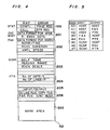
- RAM 52 consists of a plurality of areas: a status area 100 storing information representing statuses of the device 1, unit setting areas 201 through 205 for storing set values relative to respective function units, a flag area 206, and a work area 300 comprising various kinds of buffers and the like.
- the CCD read control portion 54 is operated when the device 1 working as a facsimile device is in a transmission mode, a copy mode or a scanning mode.
- the mechanism and record control portion 67 includes a slave CPU and is caused to act in a printing mode in addition to the above modes. Such a construction made of the combination of the CCD read control portion 54 with the mechanism and record control portion 67 is substantially the same as that of generally known facsimile devices.
- a scanning panel 60, shown in Fig. 3, of the image scanner 2 is formed of a transparent sheet such as glass or the like, on which panel 60 a document to be read is placed.
- the document is fixed on the scanning panel 60 by a white plate (not shown).
- Under the scanning panel 60 is provided the CCD sensor 58 extending in the main scanning direction.
- the CCD sensor 58 is moved by a motor 59 in the subscanning direction intersecting perpendicularly to the main scanning direction.
- a fluorescent lamp (not shown) as light source is placed near the CCD sensor 58 and is moved together with it. Light coming from the light source irradiates the document and the light reflected by the document is introduced into the CCD sensor 58.
- the CCD sensor 58 is caused to carry out the reading operation by timing pulses transferred from a driver 57 controlled by the CCD read control portion 54.
- Analog signals outputted from the CCD sensor 58 are supplied to an analog regulating circuit 56, in which the analog signals are converted to a digital form in accordance with a predetermined density level or slice level. Obtained image data in a digital form are supplied to the CCD read control portion 54.
- the analog signals outputted from the CCD sensor 58 are converted to a digital form according to a predetermined HALF tone level.
- the image data obtained in either way is stored in a line memory 55 connected to the CCD read control portion 54 and having a capacity for information in one line of a document and then the data for each line is outputted therefrom to the data bus DB.
- a mechanism control section of the mechanism and record control portion 67 drives a motor 59 so as to transfer the CCD sensor 58 line by line in the subscanning direction, whereby reading operation is effected line by line. If necessary, the CCD sensor 58 is caused to skip lines.
- the mechanism and record control portion 67 contains not only the mechanism control section but also an image printer control section, including a line buffer for storing line data to be recorded.
- the image printer 3 is provided with a thermal head 63 extending in the main scanning direction for line printing, which head 63 is pressed onto a platen 68 with paper 65 therebetween.
- the motor 64 causes the platen 68 to rotate in a direction according to a command transferred from the record control section of the mechanism and record control portion 67 each time image data for one line is transferred.
- the thermal head 63 is driven by a driver 62 so as to record an image based on the image data stored in the line buffer of the mechanism and record control portion 67.
- the image data to be recorded is supplied to the thermal head 63 in a digital form of binary values through the data bus DB and then the interface 66.
- the image data codec control portion 69 controls the encoding of modified Huffman (MH) or modified relative element address designate (MR) compression codes of CCITT standard into binary data and the decoding of the latter into the former.
- This encoding and decoding control technique is well known in facsimile devices generally used.
- the image data codec control portion 69 is operated when (1) the device 1 is in a facsimile status, (2) image data read by the image scanner 2 is compressed and then transferred to the personal computer 8, (3) compression data sent from the personal computer 8 is recorded by the image printer 3, and (4) binary image data outputted from the personal computer 8 is transmitted via facsimile. Accordingly, the image data codec control portion 69 is comprised of algorithms, buffers, and the like for encoding and decoding.
- the facsimile control unit 4 for controlling transmission and reception via facsimile is substantially same as a transmission control system for a facsimile device in general use.
- the facsimile transmission control portion 70 contains a slave CPU for controlling data transmission procedure based on the CCITT standard and exchanges data with the data bus DB according to the transmission procedure.
- the facsimile transmission control portion 70 is connected to the telephone line 4a through a MODEM 71 and a network control unit (NCU) 72.
- An automatic dial unit 73 connects the circuit according to dial information provided by the personal computer 8. For a manual dialing operation, a telephone is connected to the NCU 72.
- the parallel interface connecting the personal computer 8, external device, to the device 1 is provided with a buffer for data of one bite, for example.
- the personal computer 8 supplies the parallel interface 5 with various kinds of commands and data, whereby the above mentioned units transfer data to each other.
- the personal computer 8 is substantially of the same construction as other personal computers in general use.
- the personal computer 8 is connected to the device 1 by connecting parallel interfaces of the personal computer 8 and of the device 1 through a cable 7.
- the personal computer 8 controls the device 1 by outputting various kinds of commands to the device 1 in accordance with programs stored in advance in RAM or ROM in itself. So, such various functions as before mentioned can be realized by operating the personal computer 8.
- image data supplied by the device 1 can be displayed on the CRT display unit of the personal computer 8 and/or filed in a floppy disk by the floppy disk device of the personal computer 8, in the meanwhile, image data produced according to a program of the personal computer 8 can be transferred to the device 1 so as to be recorded and/or transmitted via facsimile.
- An interface 53 is for connecting the operating panel 6 shown in Fig. 2 to the buses DB, AD, CB, as shown in Fig. 3.
- the device 1 has following functions:
- the device 1 When the COPY key 41 is depressed, the device 1 starts operation.
- the image scanner 2 reads image data of a document to be copied and supplies the image printer 3 with it so that the image printer 3 may print the document.
- the device 1 encodes image data read by the image scanner 2 into compression codes by means of the image codec control portion 69 and transmits the encoded data via facsimile by means of the facsimile control unit 4. Also, the device 1 decodes information received via facsimile through the telephone line 4a into binary data by means of the image data codec control portion 69 and records it by means of the image printer 3.
- the device 1 outputs image data read by the image scanner 2 to the personal computer 8.
- the personal computer 8 displays the data on the CRT display unit and/or files it in a floppy disk
- the image printer 3 of the device 1 records image data transferred by the personal computer 8.
- the device 1 outputs image data received via facsimile to the personal computer 8, which displays the data on the CRT display unit and/or files it in a floppy disk.
- the device 1 transmits image data outputted from the personal computer 8 through the telephone line 4a.
- the device 1 converts binary data or compressed data, of an image, outputted by the personal computer 8 into compressed or binary data, respectively, at the image data codec control portion 69. And,
- control commands which the personal computer 8 outputs in order to control the device 1.
- the device 1 reports on (1) whether or not the remote control is available, (2) whether or not there are errors, (3) whether or not the previous operation has been completed, (4) whether or not a next page is required in the facsimile reception, (5) whether or not a call is requested in the facsimile transmission, and (6) whether or not paper is required to be supplied to the image printer.
- the status data in relation to the above are stored in the status area 100 of the RAM 52 as shown in Fig. 4.
- condition setting is partially presented hereinafter.
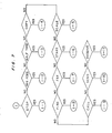
- the combination is determined by coded set values shown in Fig. 5 accompanied by a code representing this command.
- the set values corresponding to the above unit setting conditions are stored in the respective areas of RAM 52 as shown in Fig. 4 and some of them are read out and supplied to the respective units according to commands.
- the device 1 of the above construction acts as follows:
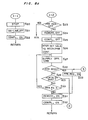
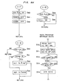
- Figs. 6 through 10d are flow charts showing programs to be carried out by the device 1. The following description is given according to those figures (the personal computer 8 will be referred to as a host hereinafter).
- step S1 every circuit element and input portions are initialized so as to be in a reset status. Then, at step S2, initial values for the whole device 1 are set and stored in the area 201 of RAM 52. For example,
- step S3 initial values for the facsimile function are set and stored in the area 202 of RAM 52. For example,
- initial values for the scanning function are set and stored in the area 203 of RAM 52. For example,
- step S5 initial setting for the printing function is carried out and set values are stored in the area 204 of RAM 52.
- set values are stored in the area 204 of RAM 52.
- step S6 the on-line flag in the area 206 of RAM 52 is set to be off so as to enable the local or off-line control. All initial setting is completed at this step.
- step S7 it is discriminated whether or not the printer 3 is running out of paper, in other words, paper is required to be supplied.
- the program proceeds to step S8, at which PAPER REQUEST status is set on and the lamp 28 on the operating panel 6 shown in Fig. 2 is turned on.
- step S9 it is discriminated whether or not some key on the panel 6 is operated and when it is judged that there is no key operation, the program proceeds to step 10, at which it is discriminated whether or not the device 1 has received data from the host 8. With a negative answer, the program returns to step S7 and repeats steps S7, S9 and S10 in order to wait for some input from keys on the operating panel 6 or from the host 8.
- the local (off-line) control or the remote (on-line) control is started when there is some key input or command from the host 8 as follows:
- step S11 When it is discriminated at step 9 that a key is operated, the program proceeds to step S11 at which it is discriminated whether or not the key is masked. When the key is masked, the key input can not be accepted, so that 25 e program proceeds to step S10.
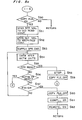
- step S12 it is discriminated at next step S12 whether or not the device 1 is under the control of the host 8, that is, the device 1 is in an on-line state. With the device 1 in an on-line state, it is discriminated at step S13 if the depressed key is STOP 22. If it is not STOP 22, the key input is not accepted and the program returns to step S7 to wait for further key input or data input from the host 8. Either when it is discriminated at step S12 that the device 1 is not in an on-line state or when it is discriminated at step S13 that the depressed key is STOP 22, the program proceeds to shown in Fig. 7 and processing under the local control is carried out.
- step S20 a task being carried out is stopped and instructions to finish are transferred to each control portion.
- the instructions cause each control portion to keep a waiting state till it receives next instructions.
- the task stop is effected by recognizing the finish of a control command even when the task is done under the control of the host 8.
- step S21 the on-line flag is turned off (when the on-line flag has been off, the flag state does not change.).
- step S22 the completion flag indicating the completion of the operation is turned on.
- the program returns to the step S7 of Fig. 6 and repeats steps S7, S9 and S10 so as to wait for a further key input.
- step S23 it is discriminated whether or not the paper request status is OFF.
- the program returns to step S7 without feeding paper.
- the program proceeds to step S24, at which the remote status (in the area 100 of RAM 52 of Fig. 4) is turned off, whereby the control by the host 8 is prohibited.
- the completion status is turned off in order to show that the device 1 is in operation.
- a preset value stored in the area 204, in relation to the printer (in this case, number of dots for line feed) is supplied to the mechanism and record control portion 67.
- step S27 transfer of operating instructions (in this case, instructions to feed a line) to the control portion 67 follows the supply of the set value.
- the mechanism and record control portion 67 determines the dot quantity for paper feed or dots per line and then determines the revolution quantity of the motor 64 based on the dot quantity for paper feed. Thereafter, the control portion 67 drives the motor 64.
- step S28 discriminations on the paper request and on the reception of data from the host 8 are done at steps S28 and S29, respectively.
- step S28 the program goes to step S33 where the paper request status is turned on (the lamp 28 is turned on). And then, at step S31, the remote status is turned on and thereafter, at step S32, the completion status is turned on to finish this operation.
- step S200 of Fig. 9 the program proceeds to step S30, at which it is discriminated whether or not the PAPER FEED key 24 is still depressed.
- steps S27 through S30 are repeated till the PAPER FEED 24 is released.
- the program returns to step S7 of Fig. 6 via steps S31 and S32.
- step S34 the scanner setting area 203 of RAM 52 shown in Fig. 4 is set for a HALF tone mode and the program returns to step S7 of Fig. 6.
- the set value corresponding to the HALF tone mode is supplied to the CCD read control portion 54 according to the instructions, given later, to read an image.
- the CCD read control portion 54 determines to which one of a plurality of slice levels fixedly set in advance each one of picture elements corresponds, and provides the analog regulating circuit 56 with digital data in accordance with respective determined levels.
- the CCD read control portion 54 determines the black level arrangement for each of the picture elements according to the digital values provided by the analog regulating circuit 56, as a model HALF tone, for example, and outputs the black level arrangement as read data.
- Such technology is generally known.
- step S40 it is discriminated whether or not the paper request status is ON. If so, the program returns to step S7 of Fig. 6 in order to prohibit the acceptance of this key input. If not, the program proceeds to step S41, at which the REMOTE status is turned off, if it is in an ON-state, so as to prohibit the control by the host 8. Then, at step S42, the COMPLETION status is turned off so as to show that the device is in operation.
- step S43 the I/O setting code "47", shown in Fig. 5, of one bite is stored in the area 205 of RAM 52 of Fig. 4. This I/O setting code "47" means that the image scanner 2 is selected as an input unit and the image printer 3 as an output unit. Thus, with this code "47” the device 1 can realize the copy function by outputting image data read by the image scanner 2 to the image printer 3 and recording the image data.
- step S44 the copy flag is turned on and then, the program returns to step S7 of Fig. 6 and repeats steps S7, S9 and S10 so as to wait for another key input.
- step S45 discrimination on the COPY flag is carried out.
- this flag is not ON, the program returns to step S7 of Fig. 6 in order to prohibit the acceptance of this key input.
- the program advances.
- steps S46 and S46 ⁇ the previous scale setting is confirmed by discriminating whether or not the previous scale setting is A4/A4 and then whether it is A4/B5 or not.
- each depression of the SCALE key 42 changes the scale setting in order according to the arrangement order. So, if the discrimination result at step S46 says that the previous setting is A4/A4, the scale is set to A4/B5 at step S49.
- the scale is set to A4/A5 at step S48.
- the previous scale setting is judged to be neither A4/A4 nor A4/B5 at steps S46 and S46 ⁇
- the scale is set to A4/A4 at step S47.
- the newly set value is stored in the area 209 of RAM 52 and either one of the lamps 44, 45 and 46 (See Fig. 2) is turned on in conformity with the set value, and thereafter the program returns.
- step S50 discrimination on the COPY flag is carried out.
- this flag is not ON, the program returns to the step S7 of Fig. 6 so as to prohibit the acceptance of this key.
- the program from step S51 on is carried out based on the I/O setting effected at foregoing step S43.
- step S51 the set value stored in the area 203 for the scanner setting is supplied to the CCD read control portion 54.
- step S52 the set value stored in the area 204 for the printer setting is supplied to the mechanism and record control portion 67 together with the above set value for the scanner.
- step S53 operating instructions are given to both control portions 54 and 67, whereby the document reading and recording are started.
- step S54 data read and outputted by the image scanner 2 keeps being transferred to the image printer 3 line by line according to the subroutine of data transfer between units (which subroutine will be referred to later) shown in Fig. 8d till the document scanning for the preset reading range (stored in the scanner setting area 203 of RAM 52 of Fig. 4) is completed.
- step S55 it is discriminated whether or not paper is required at step S55.
- the processing is stopped like by operating the STOP key at step S58, and then the copy flag is turned off at step S59. Thereafter, the program goes to step S33 of Fig. 8a.
- the program proceeds to step S200 of Fig. 9.
- step S57 it is discriminated whether or not the above routine has been finished. With the answer in the affirmative, the COPY flag is turned off at step S60, the COMPLETION status is turned on at step S61 and then the REMOTE status is turned on at step S62. After that, the program returns to step S7 of Fig. 6.
- step S70 the set value of a bite for the I/O setting code "47" is read out of the area 205 of RAM 52.
- the input and output units are determined by the set value.
- step S71 instructions to transfer data is given to the CCD read control portion 54 as an input.
- this control portion 54 drives the driver 57 and analog regulating circuit 56 to cause them to read one line data and convert the data into a digital form.
- the digital data is latched or taken hold of in a buffer inside of the CCD read control portion 54.
- the motor 59 is driven by the mechanism and record control portion 67 so as to move the CCD sensor 58 to the next line.
- the data latched in the buffer is transferred on the data bus DB to the mechanism and record control portion 67.
- the printer is in operation (e.g. recording the previous line of document) when the data is outputted toward the mechanism and record control portion 67, that data is temporarily stored in the line buffer inside the mechanism and record control portion 67.
- the data transfer from the CCD read control portion 54 to the mechanism and record control portion 67 may be done directly by means of a DMA controller, for example, or alternatively it may be done through the intermediary of the work area 300 of RAM 52.
- the above operation is effected by a time-sharing system.
- the CCD read control portion 54 When the set scale is a reduced one such as A4/B5 or A4/A5, the CCD read control portion 54 performs a predetermined selection of data in the main and subscanning directions in reading data. Accordingly, document recording on a reduced scale is obtained by recording the selected data. Recording document on a magnified scale is done likewise.
- the FAX flag is turned on, the REMOTE status is turned off and the COMPLETION status is turned off at respective steps S80, S81 and S82.
- the device 1 is set for a facsimile mode like a facsimile device of general use and the program returns to step S7 of Fig. 6 and repeats steps S7, S9 and S10. Following procedure is taken in accordance with key input of FINE, CALL, RECEIVE or SEND key.
- step S90 it is discriminated whether or not the FAX flag is ON. With this flag being OFF, the program returns to step S7 of Fig. 6 in order to prohibit the acceptance of this key input.
- the flag is ON, the program proceeds to step S91, at which a previous set value, stored in the area 202 of RAM 52, in relation to line density is confirmed by discriminating whether the previous line density is of the normal mode.
- step S92 value to be stored in the area 202 is set for the fine mode at step S92 and thereafter, the program returns.
- the line density is discriminated not to be of the normal mode at step S91, it is reset for the normal mode at step S93 and the program returns to step S7 of Fig. 6.
- the lamp 34 on the operating panel 6 of Fig. 2 is turned on.
- step S94 it is discriminated whether or not the FAX flag is ON. With this flag being OFF, the program returns to step S7 of Fig. 6 so as to prohibit the key input of this key.
- the program proceeds to step S95, at which the CALL status in the status area 100 of RAM 52 is turned on and the program returns.
- the call request is accepted at the end of the facsimile transmission. After completing such a condition setting, data transmission or reception is carried out by the depression of the SEND or RECEIVE key as will be described later.
- the key operation in sending data is done when the circuit connection is completed, while that in receiving data is done when the circuit connection is realized by data incoming.
- step S100 it is discriminated whether or not the FAX flag is ON. With this flag being OFF, the program returns to step S7 of Fig. 6 and prohibits the acceptance of the key input of SEND key 33. On the other hand, when the flag is ON, which means that the circuit connection has been completed, the program proceeds to step S101, at which I/O setting code "46" is stored in the I/O setting area 205 of RAM 52 of Fig. 4. As shown in Fig. 5, this code means that an input unit is the image scanner 2 and that an output unit is the unit 4 required for the communication via facsimile.
- step S102 the set values stored in the scanner setting area 203 and the set values stored in the facsimile setting area 202 in relation to line density are transferred to the CCD read control portion 54 and the mechanism and record control portion 67, respectively, in the similar manner as the case of the copy mode.
- step S103 the data format for transfer (compression code) stored in the facsimile setting area 202 of RAM 52 is transferred to the image data codec control portion 69, and then, at step S104, each of the set values stored in the area 202 of Fig. 4 is transferred to the facsimile transmission control portion 70.
- the line density is set for 4 lines/mm or 8 lines/mm and the image reading is carried out with resolution based on the line density selected.
- the image data codec control portion 69 is caused to convert binary image data into run length codes when the data format for transfer has been set for the modified Huffman codes.
- the facsimile transmission control portion 70 can control the outputting of the image data into the line 4a in accordance with the data transmission procedure based on the CCITT standard.
- step S105 operating instructions are given to the respective control portions, whereby at step S106 the subroutine of "data transfer between units" (See Fig. 8d) on the data bus DB is carried out.
- the data transfer subroutine is repeated twice.
- image data for one line is transferred on the data bus DB from the CCD read control portion 54 (a first input unit) to the image data codec control portion 69 (a first output unit), where the image data is encoded by the modified Huffman encoding method.
- the modified Huffman encoded data is transferred on the data bus DB from the image data codec control portion 69 (the first output unit and a second input unit) to the facsimile transmission control portion 70 (a second output unit).
- the image data (binary data) read by the image scanner 2 is stored in the line memory 55 and then the data is transferred to the facsimile transmission control portion 70 bite by bite.
- the above data transfer operation is carried out repeatedly by repeating steps S105 to S110 for every line.
- step S108 discriminations on the data reception from the host 8, depression of a key, and task finish of the CCD read control portion 54 and of the facsimile transmission control portion 70 are carried out, respectively.
- step S108 the program proceeds to step S200 of Fig. 9.
- step S109 the program returns to of Fig. 7 so as to identify the key.
- the processing in a call mode is carried out by the facsimile transmission control portion 70 because the CALL status is ON.
- the facsimile transmission control portion 70 outputs a discrimination code for the task end, by which code the end of task is confirmed.
- the CALL status is turned off at step S114, the REMOTE status is turned on at step S115, and the COMPLETION status is turned on at step S116, whereby the data transmission process is completed. Then, the program returns to step S7 of Fig. 6.
- the I/O setting code "44" is stored in the I/O setting area 205 of RAM 52 at step S122. With this code, the facsimile 4 is set as an input and the image printer 3 as an output. Then, at step S123, a set values stored in the printer setting area 204 of RAM 52 is transferred to the mechanism and record control portion 67. After that, the program proceeds to step S103 of the data transmission routine (1-10) of Fig. 8e. From this step on, the data reception routine is carried out according to said data transmission routine except for the step S106. Therefore the same description on those steps is omitted here.
- step S106 In the data transfer process between units carried out at step S106 (See Fig. 8d), which is repeated twice like in the data transmission process, modified Huffman encoded data received from the facsimile transmission control portion 70 (a first input unit) through the telephone line 4a is transferred to the image data codec control portion 69 (a first output unit), by which the modified Huffman codes are decoded into binary data.
- the decoded data in the binary form is transferred from the image data codec control portion 69 (a second input unit) to the mechanism and record control portion 67 (a second output unit).
- This two-step data transfer operation is carried out repeatedly for every line by repeating the steps S105 to S110.
- step S111 If paper shortage is detected during the data reception process at step S107, the program proceeds to step S111, at which it is discriminated whether or not the device 1 is of a transmission mode. With a negative answer, the program proceeds to step S112, at which an error discrimination code is supplied to the facsimile transmission portion 70 for error processing and at the same time the ERROR status is turned on (the lamp 27 on the operating panel 6 shown in Fig. 2 is turned on). After that, the PAPER REQUEST status is turned on at step S113, and then the program proceeds to step S114 to end this data reception process.
- the device 1 is adapted to respond to this command even while it is doing some task.
- step S10 of Fig. 6 When the device 1 receives this command from the host 8 at step S10 of Fig. 6, step S29 in (1-2) of Fig. 8a, step S56 in (1-8) of Fig. 8c, step S108 in (1-10) of Fig. 8e, step S234 in (2-2) (described later) of Fig. 10a, or step S243 in (2-3) (described later) of Fig. 10b, the program proceeds to step S200 of Fig. 9.
- step S200 it is discriminated whether or not the received command is STATUS REQUEST command. With an answer in the affirmative, the program proceeds to step S201, while with an answer in the negative, it proceeds to step S203.
- step S201 data stored in the area 100 for status setting of RAM 52 is read out.
- step S202 the read data of one bite in relation to the status of the device 1 is transferred to the host 8 through the parallel interface 5. Thereafter, the program returns to step S7 to repeat steps S7, S9 and S10 waiting for the next key depression or the next command from the host 8.
- step S203 it is discriminated whether or not the REMOTE status is ON.
- the program proceeds to step S204, at which data "BREAK" is transferred to the host 8 through the parallel interface 5 and then the program returns to step S7 so as to wait for a further key operation or command from the host 8.
- step S204 data "BREAK" is transferred to the host 8 through the parallel interface 5 and then the program returns to step S7 so as to wait for a further key operation or command from the host 8.
- the host 8 confirms that it has transferred a wrong command to the device 1.
- the program skips to step S205.
- step S205 passing steps S200 and S203 through, it is discriminated whether or not the command transferred from the host 8 is STOP command. If it is so, the program proceeds to step S206, at which it is discriminated whether or not the ON-LINE flag is in an ON-state. If it is in an OFF-state, that is, the device 1 is not operating under the control of the host 8, the program returns to step S204, at which the data "BREAK" is outputted to the host 8 because STOP command is a wrong command.
- the device 1 stops the operation actually being carried out at step S207. This corresponds to the operation of STOP key in the OFF-LINE control. Subsequently to the operation stop, the ON-LINE flag is turned off at step S208, the REMOTE status is turned off at step S209, the COMPLETION status is turned on at step S210, and then the program returns to step S7 and waits for the next key operation or command from the host 8.
- step S205 When the received command is discriminated not to be STOP at step S205, the program proceeds to step S211, at which the received command is checked. At step S212 it is discriminated if the received command is acceptable with respect to the data format, command transfer procedure, etc. When it is unacceptable because the command has not been transferred prior to corresponding data transfer, for example, the program goes to step S204 to transfer the data "BREAK" to the host 8 and returns to step S7 of Fig. 6. When the received command is judged to be acceptable at step S212, the ON-LINE flag is turned on at step S213 so that control may be carried out in accordance with the command.
- the command transfer process is determined in advance, that is, prior to data transfer form the host 8 to the device 1, UNIT SETTING command described in detail later is transferred to RAM 52 together with the initial setting data for each of the functions or set values to be stored in the respective areas 201 to 204 of RAM 52. After that, I/O SETTING command for specifying the input and output units is transferred to RAM 52 together with one of the preset unit setting codes of one bite (See Fig. 5).
- the host 8 transfers DATA TRANSFER command to the device 1.
- the device 1 transfers data "ACK” (acknowledge) or "NAK” (negative acknowledge) to the host 8 in reply to the command.
- the host 8 prepares to transfer the next command in accordance with the reply.
- This command is for effecting initial setting for the respective functions of the device 1 and consists of a device designating code of one bite for discerning the facsimile, scanner and printer from each other.
- This command is accompanied by the set values of a plurality of bites to be stored in the respective areas 201 to 204 of RAM 52.
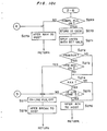
- the program advances to step S214 via steps S200, S203, S205, S211, S212 and S213. If the received command is discriminated to be UNIT SETTING at step S214, (2-1) of Fig. 10a is carried out. If not, the program proceeds to step S215.
- step S230 the set values are put into the corresponding area 201, 202, 203 or 204 of RAM 52 in conformity with the transferred device code. Then, at step S231 the device 1 forwards the data "ACK" to the host 8 through the parallel interface 5 and the program returns to step S7 of Fig. 6.
- the host 8 After receiving the data "ACK”, the host 8 starts preparing for the next command transfer.
- the host 8 outputs the UNIT SETTING command repeatedly when it requires further devices to be set.
- This command is for shifting the CCD sensor 58 in the image reading process so that the CCD sensor may skip document of a range unnecessary to read.
- Value representing the shift or skip quantity, which consists of a plurality of bites, follows the SCANNER'S SKIP command of one bite.
- step S215 When it is discriminated at step S215 that the received command is SCANNER'S SKIP, the program branches to (2-2) of Fig. 10a. If not SCANNER'S SKIP, the program proceeds to step S216.
- the COMPLETION status is turned off at step S232, and then the set value for scanner's skip quantity is supplied to the mechanism and record control portion 67 so that the CCD sensor 58 may be shifted.
- the mechanism and record control portion 67 drives the motor 59 according to the scanner's skip quantity. As soon as the scanner's shift is completed, a signal representing the scanner's being busy is turned off and then a signal representing the completion of the operation is outputted from the mechanism and record control portion 67.
- step S234 it is discriminated whether or not some command from the host 8 is received. With some command received from the host 8, the program proceeds to the above mentioned step S200. Furthermore, at step S235 it is discriminated whether the "scanner's being busy" signal is in an ON-state or not. With the answer in the affirmative, the program returns to step S234 and repeats steps S234 and S235 so as to wait for a further command from the host 8.
- step S236 When there is neither data reception from the host 8 nor the "scanner's being busy" signal in an ON-state, the program proceeds to step S236, at which the COMPLETION status is turned off. Subsequently the data "ACK" is transferred to the host 8 at step S237 and then the program returns to step S7 of Fig. 6.
- the host 8 After receiving the data "ACK”, the host 8 starts preparing for the next command transfer.
- This command is for specifying input and output units, consisting of one bite.
- the host 8 outputs one of the predetermined I/O setting codes shown in Fig. 5 to RAM 52 according to a given program for the host 8. The code is put into the I/O setting area 205 of RAM 52.
- the host 8 transfers the UNIT SETTING command to the device 1 to store set values for the scanner in the corresponding area of RAM 52.
- the host 8 outputs the setting code "45" together with the I/O SETTING command to the device 1.
- the image scanner 2 is determined as an input unit and the host 8 as an output unit, as shown in Fig. 5.
- the program carries out a routine (2-6) of Fig. 10c due to the I/O SETTING command.
- step S269 it is discriminated whether the COMPLETION flag is in an ON-state or not.
- the program proceeds to step S270.
- step S279 the device 1 transfers the data "NAK" to the host 8 to let it know that the image scanner 2 is not ready yet.
- the I/O setting code "45" gets stored in the corresponding area 205 of RAM 52. Thereafter, at step S271 the set values stored in the area 203 of RAM 52 are transferred to the corresponding control portions in accordance with the code "45".
- the set values stored in the scanner setting area 203 of RAM 52 are supplied to the CCD read control portion 54 and to the mechanism and record control portion 67.
- the value, stored in the device setting area 201 of RAM 52 in relation to the data format for data transfer represents modified Huffman compression codes, instructions to convert data into modified Huffman codes are given to the image data codec control portion 69.
- step S272 it is discriminated whether or not the image printer 3 is selected as an output unit.
- the discrimination at this step gives an answer in the negative.
- the program skips to step S274, at which it is discriminated whether the facsimile 4 is selected as an output unit.
- step S276 at which the device 1 provides the host 8 with the data "ACK”.
- the program returns to step S7 of Fig. 6.
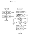
- the data "ACK" confirms the host 8 that the unit setting has been completed. Therefore, the host 8 starts preparing for receiving data from the device 1. When the host 8 gets ready, it outputs the DATA TRANSFER REQUEST command to the device 1. On receiving the command, the device 1 carries out a routine (2-7) of Fig. 10d.
- step S280 it is discriminated whether or not "BUSY" signal indicating that an input unit or an output unit designated by the I/O setting code is in operation is in an ON-state.
- "BUSY” signal outputted from the CCD read control portion 54 is checked for the discrimination whether the image scanner 2 is in operation or not.
- the program proceeds to step S279 at which the "NAK" data is transferred to the host 8, and it returns to step S7 of Fig. 6.
- the host 8 receives the data "NAK”, the host 8 outputs the DATA TRANSFER REQUEST command to the device 1 over and over again till the image scanner 2 gets ready for outputting data to the host 8. Then, the program proceeds to step S281.
- step S281 operating instructions are given to the designated units according to the I/O setting code stored in the area 205 of RAM 52. That is, the CCD read control portion 54 and mechanism and record control portion 67 receive the operating instructions and control the image scanner 2 to read document line by line in the same manner as in the copy mode (See Fig. 8c). The read data for one line is stored in the line memory 55.
- step S282 If completion of the image reading is confirmed as a result of the discrimination at step S282, the program proceeds to step S283, at which the device 1 outputs the data "ACK" to the host 8. If the image reading is not completed yet, the step S282 is repeated till the completion is confirmed. At step S284, it is discriminated whether or not the device 1 is required to receive data from the host 8. As the device 1 is supposed to transfer data read by the image scanner 2 to the host 8 in this case, the program proceeds to step S285.
- the data transfer between control portions is carried out based on the subroutine shown in Fig. 8d.
- the CCD read control portion 54 provides the parallel interface 5 with obtained image data since the host 8 is designated as an output unit.
- the CCD read control portion 54 In transferring line data to the host 8, if the device setting area 201 of RAM 52 sets the data transfer format to the modified Huffman codes, the CCD read control portion 54 once forwards the image data of one line to the image data codec control portion 69 where the data is encoded by the modified Huffman compression encoding method.
- the modified Huffman compression codes so obtained are finally transferred to the host 8.
- modified Huffman compression data is of shorter bit length than binary data, so that the host 8 selects the modified Huffman compression encoding in the case of filing data in a floppy disk or in the like case, though this compressed data is decoded into binary data again when displayed on the CRT display unit, etc.
- step S287 it is discriminated whether or not the image printer 3 is designated as an output unit. As the printer 3 is not designated as an output unit in this case, the program returns to step S7 of Fig. 6 so as to wait for another DATA TRANSFER REQUEST command. When the device 1 receives this command, image data of the next line is read. This process is repeated till reading of image data for every line is completed.
- the host 8 When data of predetermined quantity has been read, the host 8 outputs the STOP command to stop the on-line control.
- control by the host 8 enables the device 1 to read image : ⁇ the portion of the image scanner 2 and provide it to the host 8, so that the host 8 can output the incoming data on the CRT display unit or file it in a floppy disk by means of the floppy disk device, etc.
- the host 8 In recording image data generated in the host 8 as a result of execution of a program for the host 8 or image data filed in the floppy disk, the host 8 forwards the I/O setting code "42" together with the I/O SETTING command to the device 1. This code assigns the host 8 to the input unit and the image printer 3 to the output unit.
- the routine (2-6) of Fig. 10c is also carried out in this case. The following describes only steps different from the above case.
- the I/O setting code "42" gets stored in the corresponding area 205 of RAM 52. Then, at next step S271, set values stored in advance in the printer setting area 204 and the device setting area 201 of RAM 52 are read out and the set values for the printer 3 are supplied to the mechanism and record control portion 67. When values on the data transfer format in the area 201 of RAM 52 are set for the modified Huffman codes, instructions to decode incoming data are given to the image data codec control portion 69.
- step S272 In the discrimination on the output unit setting at step S272, an answer in the affirmative is obtained because the I/O setting code designates the image printer 3 as an output unit in this case. So the program proceeds to step S273, at which it is discriminated whether the PAPER REQUEST status is ON or not. If the status is ON, the program proceeds to step S277, at which the ON-LINE flag is turned off and then, at step S278, the data "BREAK" is transferred to the host 8. The programs returns to step S7 of Fig. 6 at this point.
- step S273 When the PAPER REQUEST status is discriminated to be OFF at step S273, the program proceeds to step S276 via step S274.
- the device 1 forwards the data "ACK" to the host 8 at step S276 and then the program returns to step S7 of Fig. 6 so as to wait for a further commands.
- step S284 it is discriminated whether or not the the host 8 requires the device 1 to receive data from the host 8.
- the input unit for this case is the host 8
- the device 1 is required to receive data from the host 8.
- the host 8 starts forwarding a line data to the device 1.
- the program advances to step S285 at which the data corresponding to each line is transferred to the record control section of the mechanism and record control portion 67 together with the DATA TRANSFER command according to the subroutine of "data transfer between units" shown in Fig. 8d.
- step 287 it is discriminated that the printer 3 is designated as an output unit, and so, the program proceeds to step S288 at which discrimination on paper shortage or paper request is carried out.
- the program proceeds to step S277 of Fig. 10c, where the ON-LINE flag is turned off, and subsequently the data "BREAK" is forwarded to the host 8. Then, the program returns to step S7 of Fig. 6.
- the program immediately returns to step S7 so that the device 1 may be brought into a waiting state.
- step S240 set values stored in advance in the printer setting area 204 of RAM 52 (See Fig. 4) are read out and transferred to the mechanism and record control portion 67. Then, at step S242, the mechanism and record control portion 67 is given instructions to carry out the command. Therefore, the mechanism and record control portion 67 carries out the command according to the transferred set values.
- PRINTER CONTROL command e.g. line feed command
- step S243 it is discriminated whether or not the device 1 has received some other command from the host 8.
- the program returns to step S200. Without any other command, the program proceeds to step S244 at which it is discriminated whether or not signal representing image printer 3 is in some operation is in an ON-state. With the signal in an ON-state, the program returns to S243 and these steps S243 and S244 are repeated in turn till the signal is turned off, that is, the image printer gets ready.
- the "BUSY" signal is in an OFF-state, the programs returns to step S7 of Fig. 6 via steps S245 and S246 at which the COMPLETION status is turned off and then the data "ACK" is forwarded to the host 8.
- the device 1 transfers the data "BREAK" to the host 8 at step S278 as described before.
- the host 8 When the printing operation finishes, the host 8 outputs the STOP command to stop the control.
- the host 8 In transmitting image data produced in the host 8 or image data filed in the floppy disk via facsimile using the telephone line 4a connected to the device 1, the host 8 outputs the I/O setting code "41" to the device 1. This code assigns the host 8 to the input unit and the facsimile 4 to the output unit.
- the routines (2-6) and (2-7) of Fig. 14 are carried out as follows (though steps for the processing similar to foregoing one are omitted):
- the circuit is connected for the data transmission by a manual dialing or an automatic dialing under the control of the host 8.
- step S274 it is discriminated whether or not the facsimile 4 is designated as an output unit.
- the program proceeds to step S275, at which it is discriminated by checking signal outputted by the facsimile transmission control portion 70 whether or not the circuit is connected.
- step S277 at which the ON-LINE flag is turned off.
- the device 1 forwarding the data "BREAK” to the host 8, the program returns to step S7 of Fig. 6.
- step S7 of Fig. 6 On the other hand, when the circuit is connected, the data "ACK" is transferred to the host 8. Then the program returns to step S7 of Fig. 6 and repeats steps S7, S9 and S10 to wait for the next command from the host 8.
- the program carries out (2-4) of Fig. 10b.
- step 250 the CALL status in the area 100 of RAM 52 is turned on.
- step S251 instructions to give a call are given to the facsimile transmission control portion 70. Further processing is done similarly to the facsimile transmitting operation under the local (off-line) control.
- the host 8 forwards the PAGE REQUEST command to the device 1, whereby the program carries out (2-5) of Fig. 10b as follows:
- step S260 the PAGE REQUEST status in the area 100 of RAM 52 is turned on due to the PAGE REQUEST command.
- step S261 instructions to require the next page of data are given to the facsimile transmission control portion 70.
- the device 1 transfers the data "ACK" to the host 8, whereby the transfer of data of the next page is carried out in conformity with the CCITT standard.
- the host 8 After confirming the circuit connection (not shown in the flow chart), the host 8 outputs the I/O setting code "43" together with the I/O SETTING command.
- This code means that the facsimile 4 and host 8 are input and output units, respectively (See Fig. 5).
- the program On receiving the I/O SETTING command, the program carries out the (2-6) and then the (2-7).
- the data transfer from the device 1 to the host 8 is started by receiving the DATA TRANSFER command.
- Data format for the transfer to the host 8 is determined by the data stored in the device setting area 201 of RAM 52.
- This task is carried out when the I/O setting code "40" is transferred from the host 8.
- Set values indicative of I/O data format stored in the area 201, that is, MH /MR codes or binary data, are read out and supplied to the image data codec control portion 69, whereby encoding or decoding is effected.
- Binary data or modified Huffman codes obtained through the conversion processing are sent back to the host 8.
- DATA RECEPTION REQUEST command and DATA TRANSFER REQUEST are outputted alternately.
- the host 8 transfers DATA RECEPTION REQUEST command to the device 1 so as to transfer line data encoded by the modified Huffman encoding method to the image data codec control portion 69, which decodes the incoming modified Huffman codes into binary data and stores it in the work area 300 of RAM 52 temporarily.
- the host 8 transfers DATA TRANSFER REQUEST command to the device 1 so that the device 1 transfers the binary data corresponding to one line of document back to the host 8. The above is repeated for every line.
- the line memory 55 may be used for the temporary storage of data as an alternative of the work area 300 of RAM 52.
- a multifunctional data processing device can copy or transmit document via facsimile selectively independent of the control of the external data processing unit.
- the device of the present invention realizes further functions such as outputting image data read by the image read control unit to the external data processing unit, recording data transferred from the external data processing unit by means of the image record control unit, transmitting data received from the external data processing unit via facsimile or transferring data received via facsimile to the external data processing unit by means of the facsimile transmission control unit, and so on.
Abstract
Description
- The present invention generally relates to an image processing device connected to an external data processing device such as a personal computer or the like and more particularly, a multifunctional image processing device which, comprising a main control portion, an image read control unit, an image recording control unit, a facsimile control unit, and an interface unit for connecting a personal computer as an external unit, provides following various functions by controlling each unit with the main control portion: (1) copying document, that is, recording image information outputted from the image read control unit, (2) recording image information generated in the personal computer, (3) displaying or filing image information outputted from the image read control unit at the personal computer, (4) transmitting via facsimile image information provided by the image read control unit, (5) transmitting via facsimile image information produced at the personal computer, (6) recording incoming image information sent via facsimile and/or filing it in the personal computer, and so on.
- Following devices are known as conventional image processing systems: a device which records or prints image information read by an image scanner by means of an image printer and/or supplies a computer with it; a facsimile device which once memorizes image information received through a telephone line in an internal memory prior to recording it; and the like.
- In such conventional image processing systems, such units as the image scanner, image printer, facsimile device and personal computer are independent of each other, and therefore those systems cannot transmit image information read out of the image scanner or that produced at the personal computer via facsimile without help of the separate facsimile device. Also, the traditional systems cannot synthesize image information received by the facsimile device with another image information by using the personal computer or the like. Like this, according to the traditional systems, units having respective functions are not connected to each other internally, so that data reciprocation between units is impossible and moreover transmission of data produced by other units via facsimile are time-consuming and troublesome.
- Accordingly, the present invention has been developed with a view to substantially eliminating the above described disadvantages inherent in the prior art and has for its essential object to provide a multifunctional image processing device which has functions proper to an image recording unit such as the image scanner, to an image recording unit such as the image printer, and to the facsimile device, and can effect image transferring between such units, thereby realizing various kinds of image processing.
- In accomplishing this object, a multifunctional image processing device according to one preferred embodiment of the present invention comprises a housing; an image read control unit for reading images according to control information; a facsimile control unit for sending and receiving image information through a telephone line according to control information; an image record control unit for recording image information according to control information; an interface unit connected to an external data processing device for transferring control commands and image information to and from the data processing device; bus lines for connecting the image read control unit, facsimile control unit, image record control unit and interface unit to each other; a main control unit connected to the bus lines so as to control the information transfer between each couple of the units according to the respective control commands sent through the interface unit and control each unit individually by outputting the respective control informations thereto, all of the above units being accommodated in the housing.
- This multifunctional image processing device functions as follows:
- When the device is in an off-line control status, it is operated independently of the data processing device as an external device connected thereto through the interface unit and following functions are effected selectively.
- Image information read by the image read control unit is supplied to the image recording unit on a data bus and printed by it according to the control information transferred from the main control unit.
- The image information read by the image read control unit is transferred to the facsimile control unit and then transmitted therefrom through the telephone line, according to the control information outputted from the main control unit. On the other hand, image information received through the telephone line is recorded by the image record control unit.
- Meanwhile, when the present device is in an on-line control status, following functions are selectively executed according to control commands provided to the device by the external data processing device connected to the device.
- The image information read by the image read control unit is transferred to the data processing device on the data bus according to control commands.
- The image information sent from the external data processing device is recorded by the image record control unit.
- Image information received by the facsimile control unit through the telephone line is transferred to the external data processing device. Also, image information inputted from the external data processing device is transmitted by the facsimile control unit through the telephone line.
- Furthermore, functions corresponding to the above independent functions (1) and (2) are also effected based on the control commands provided by the external data processing device through the bus lines connected to the respective units. Moreover, the synthesis and editing of image data is executed by combining the above functions with each other, whereby various kinds of image processing are carried out without difficulties.
- These features and advantages of the present invention will become more apparent with reference to the following detailed description of a preferred embodiment thereof in connection with the accompanying drawings.
-
- Fig. 1 shows a schematic view of a multifunctional image data processing device of a preferred embodiment of the invention being connected to a personal computer;
- Fig. 2 shows an operating panel fixed to the device;
- Fig. 3 is a block diagram corresponding to the Fig. 1;
- Fig. 4 shows the construction of RAM included in the device;
- Fig. 5 shows an example of I/O setting codes;
- Fig. 6 is a flow chart of the main program for the device;
- Fig. 7 through Fig. 8e are flow charts for processes carried out in the off-line control status of the device; and
- Fig. 9 through Fig. 10d are flow charts for processes carried out in the on-line control status of the device.
- Fig. 1 schematically shows a system consisting of a multifunctional image processing device and a personal computer connected to the device, in which
reference numeral 1 designates the image processing device of multifunctional type, which includes ahousing 101; animage scanner 2 as the image read control unit for reading a fixedly mounted document line by line by means of a line CCD sensor (a line sensor constituted of a charge coupled device); animage printer 3 as the image record control unit for recording image information using a line thermal head and record paper; afacsimile control unit 4 connected to atelephone line 4a; and a bidirectionalparallel interface unit 5 for connecting the personal computer, external device 8 through acable 7. On the front face of thedevice 1 there is provided anoperating panel 6 for operating thedevice 1. The personal computer 8 is comprised of aCRT display 10, akeyboard device 9 and a floppy disk device 11. Various kinds of image processing and data processing are carried out by the computer 8 according to programs for respective applications. The personal computer 8 stores preset control commands (to be referred to later) and provides theimage processing device 1 with the control commands according to the respective application programs or input from thekeyboard 9 so as to control various kinds of image processing. - The
operating panel 6 shown in detail in Fig. 2 is comprised of anoperating portion 20 for thewhole device 1, anoperating portion 30 for the facsimile function, and anoperating portion 40 for the copy function. - In the
operating portion 20 for the device, an on-line lamp 29 is adapted to be turned on when the personal computer 8 gives the device 1 a control command so as to electrically connect thedevice 1 to the personal computer 8, that is, an on-line status is generated. In the on-line status, all keys but aSTOP key 22 on thepanel 6 are deemed to be invalid and thedevice 1 acts only under the instructions given by the personal computer 8. On the other hand, in the off-line status, all key inputs are valid and thedevice 1 rejects instructions transferred from the personal computer 8. HALF TONE 23 is a key for instructing whether to read a document by bi-level values or to read it according to a predetermined tone. When an operator orders thedevice 1 to read a document in HALF tone by depressing the HALFTONE key 23, HALFTONE lamp 23L is turned on. PAPER FEED 24 is a key used to let paper being set at theimage printer 3 to advance without printing. DENSITY ADJUST 25 is a sliding key used to adjust density with which the document is to be read. The density adjustment is carried out by varying the standard level for deciding a border between black and white.Reference numerals POWER 26 is a lamp to be turned on when thedevice 1 is powered on, WRN 27 is a lamp for indicating troubles in each of the units, andSPLY PPR 28 is a lamp for indicating shortage of the paper at theimage printer 3. - In the
operating portion 30 for the facsimile function, FACSIMILE 31 is an instructing key for causing thedevice 1 to act as a facsimile device. FACSIMILElamp 31L is turned on when thedevice 1 is set for the facsimile mode. RECEIVE 32 is a key for setting thedevice 1 to be ready for receiving via facsimile and when this setting is completed, alamp 32L is turned on. To the contrary, SEND 33 is a key for setting the facsimile for the transmission mode and when this setting is completed, alamp 33L is turned on. FINE 34 is a key for setting line density to 4 lines/mm or 7.7 lines/mm. When the latter is selected, a lamp 34L is turned on.CALL 35 is a key for requesting a call when the transmission or the reception via facsimile of a document is completed. When thiskey 35 is depressed, alamp 35L is turned on. - In the
operating portion 40 for the copy function,COPY 41 is a key for setting thedevice 1 for the document copy mode. When thiskey 41 is depressed and thedevice 1 is set for the copy mode, alamp 41L is turned on. SCALE 42 is a key to be depressed for determining scale in copying document. The scale is set to any one of A4 →A4 (same size), A4 →B5 and A4 →A5 by depressing SCALE 42 a plurality of times. Then one oflamps START 43 is a key for giving instructions to start copying.STOP 22 is a key for halting or stopping action of each unit during the operation process. - Fig. 3 is a block diagram of the
device 1 with the personal computer 8 being connected thereto.Reference numeral 50 designates a main CPU as the main control unit which controls thedevice 1 in accordance with each of system programs stored in a read-only memory (ROM) 51 in advance. To thismain CPU 50 are connected common data bus DB, address bus AB, and control bus CB. Following units are connected to each of the buses DB, AB and CB and controlled by the main CPU 50: theROM 51, a random-access memory (RAM) 52, a CCDread control portion 54 containing a slave CPU, an image datacodec control portion 69 containing a slave CPU, a facsimiletransmission control portion 70 containing a slave CPU, aninterface 53 for connecting theoperating panel 6, anotherinterface 66 for connecting a mechanism andrecord control portion 67, and theparallel interface 5 for connecting the personal computer 8. Besides the system programs,ROM 51 is also provided with a command analyzing portion for transferring data to and receiving data from the personal computer 8. - As shown in Fig. 4,
RAM 52 consists of a plurality of areas: astatus area 100 storing information representing statuses of thedevice 1,unit setting areas 201 through 205 for storing set values relative to respective function units, aflag area 206, and awork area 300 comprising various kinds of buffers and the like. - The CCD read
control portion 54 is operated when thedevice 1 working as a facsimile device is in a transmission mode, a copy mode or a scanning mode. The mechanism andrecord control portion 67 includes a slave CPU and is caused to act in a printing mode in addition to the above modes. Such a construction made of the combination of the CCD readcontrol portion 54 with the mechanism andrecord control portion 67 is substantially the same as that of generally known facsimile devices. - A
scanning panel 60, shown in Fig. 3, of theimage scanner 2 is formed of a transparent sheet such as glass or the like, on which panel 60 a document to be read is placed. The document is fixed on thescanning panel 60 by a white plate (not shown). Under thescanning panel 60 is provided theCCD sensor 58 extending in the main scanning direction. TheCCD sensor 58 is moved by amotor 59 in the subscanning direction intersecting perpendicularly to the main scanning direction. A fluorescent lamp (not shown) as light source is placed near theCCD sensor 58 and is moved together with it. Light coming from the light source irradiates the document and the light reflected by the document is introduced into theCCD sensor 58. - The
CCD sensor 58 is caused to carry out the reading operation by timing pulses transferred from adriver 57 controlled by the CCD readcontrol portion 54. Analog signals outputted from theCCD sensor 58 are supplied to ananalog regulating circuit 56, in which the analog signals are converted to a digital form in accordance with a predetermined density level or slice level. Obtained image data in a digital form are supplied to the CCD readcontrol portion 54. When the HALF tone mode is selected, the analog signals outputted from theCCD sensor 58 are converted to a digital form according to a predetermined HALF tone level. The image data obtained in either way is stored in aline memory 55 connected to the CCD readcontrol portion 54 and having a capacity for information in one line of a document and then the data for each line is outputted therefrom to the data bus DB. - A mechanism control section of the mechanism and
record control portion 67 drives amotor 59 so as to transfer theCCD sensor 58 line by line in the subscanning direction, whereby reading operation is effected line by line. If necessary, theCCD sensor 58 is caused to skip lines. The mechanism andrecord control portion 67 contains not only the mechanism control section but also an image printer control section, including a line buffer for storing line data to be recorded. - The
image printer 3 is provided with athermal head 63 extending in the main scanning direction for line printing, which head 63 is pressed onto aplaten 68 withpaper 65 therebetween. Themotor 64 causes theplaten 68 to rotate in a direction according to a command transferred from the record control section of the mechanism andrecord control portion 67 each time image data for one line is transferred. Thethermal head 63 is driven by adriver 62 so as to record an image based on the image data stored in the line buffer of the mechanism andrecord control portion 67. The image data to be recorded is supplied to thethermal head 63 in a digital form of binary values through the data bus DB and then theinterface 66. - The image data
codec control portion 69 controls the encoding of modified Huffman (MH) or modified relative element address designate (MR) compression codes of CCITT standard into binary data and the decoding of the latter into the former. This encoding and decoding control technique is well known in facsimile devices generally used. The image datacodec control portion 69 is operated when (1) thedevice 1 is in a facsimile status, (2) image data read by theimage scanner 2 is compressed and then transferred to the personal computer 8, (3) compression data sent from the personal computer 8 is recorded by theimage printer 3, and (4) binary image data outputted from the personal computer 8 is transmitted via facsimile. Accordingly, the image datacodec control portion 69 is comprised of algorithms, buffers, and the like for encoding and decoding. - The
facsimile control unit 4 for controlling transmission and reception via facsimile is substantially same as a transmission control system for a facsimile device in general use. The facsimiletransmission control portion 70 contains a slave CPU for controlling data transmission procedure based on the CCITT standard and exchanges data with the data bus DB according to the transmission procedure. The facsimiletransmission control portion 70 is connected to thetelephone line 4a through aMODEM 71 and a network control unit (NCU) 72. Anautomatic dial unit 73 connects the circuit according to dial information provided by the personal computer 8. For a manual dialing operation, a telephone is connected to theNCU 72. - The parallel interface connecting the personal computer 8, external device, to the
device 1 is provided with a buffer for data of one bite, for example. The personal computer 8 supplies theparallel interface 5 with various kinds of commands and data, whereby the above mentioned units transfer data to each other. The personal computer 8 is substantially of the same construction as other personal computers in general use. The personal computer 8 is connected to thedevice 1 by connecting parallel interfaces of the personal computer 8 and of thedevice 1 through acable 7. The personal computer 8 controls thedevice 1 by outputting various kinds of commands to thedevice 1 in accordance with programs stored in advance in RAM or ROM in itself. So, such various functions as before mentioned can be realized by operating the personal computer 8. To say concretely, image data supplied by thedevice 1 can be displayed on the CRT display unit of the personal computer 8 and/or filed in a floppy disk by the floppy disk device of the personal computer 8, in the meanwhile, image data produced according to a program of the personal computer 8 can be transferred to thedevice 1 so as to be recorded and/or transmitted via facsimile. - An
interface 53 is for connecting theoperating panel 6 shown in Fig. 2 to the buses DB, AD, CB, as shown in Fig. 3. - The
device 1 has following functions: - When the
COPY key 41 is depressed, thedevice 1 starts operation. Theimage scanner 2 reads image data of a document to be copied and supplies theimage printer 3 with it so that theimage printer 3 may print the document. - This is a function obtained when the
FACSIMILE key 31 is operated. Thedevice 1 encodes image data read by theimage scanner 2 into compression codes by means of the imagecodec control portion 69 and transmits the encoded data via facsimile by means of thefacsimile control unit 4. Also, thedevice 1 decodes information received via facsimile through thetelephone line 4a into binary data by means of the image datacodec control portion 69 and records it by means of theimage printer 3. - The
device 1 outputs image data read by theimage scanner 2 to the personal computer 8. The personal computer 8 displays the data on the CRT display unit and/or files it in a floppy disk -
- The
image printer 3 of thedevice 1 records image data transferred by the personal computer 8. - The
device 1 outputs image data received via facsimile to the personal computer 8, which displays the data on the CRT display unit and/or files it in a floppy disk. - The
device 1 transmits image data outputted from the personal computer 8 through thetelephone line 4a. - The
device 1 converts binary data or compressed data, of an image, outputted by the personal computer 8 into compressed or binary data, respectively, at the image datacodec control portion 69. And, - Functions corresponding to the above independent functions obtained when the
device 1 is in an off-line state are also effected under the control of the personal computer 8. - The following describes control commands which the personal computer 8 outputs in order to control the
device 1. - This is a command outputted when the computer 8 requests the
device 1 to report on an actual status thereof so as to control thedevice 1. In response to this command, thedevice 1 reports on (1) whether or not the remote control is available, (2) whether or not there are errors, (3) whether or not the previous operation has been completed, (4) whether or not a next page is required in the facsimile reception, (5) whether or not a call is requested in the facsimile transmission, and (6) whether or not paper is required to be supplied to the image printer. The status data in relation to the above are stored in thestatus area 100 of theRAM 52 as shown in Fig. 4. - This is a command for instructing the
device 1 to stop controlling. - This is a command for instructing the
device 1 to get ready for receiving or transmitting data prior to the starting. - This is a command for instructing the
device 1 to give a call over the telephone when the data transmission via facsimile is completed. - This is a command for instructing the
device 1 to supply data of the next page when data corresponding to a plurality of pages of document are outputted from the personal computer 8 so as to be transmitted via facsimile. - This is a command for instructing the
device 1 to determine the quantity by which theimage scanner 2 should be advanced or skip a document without scanning. - This is a command in relation to the control of the
image printer 3 such as "line feed", "page end" and so on - This is a command for instructing the
device 1 to set conditions for each of functions proper to thewhole device 1, facsimile, image scanner, and image printer. Such condition setting is partially presented hereinafter. - (a) Condition setting for the whole device
- (i) Data format for the transfer between the
device 1 and the personal computer 8.....necessity of compression, MH or MR encoding method - (ii) Validity of each key input (key masking)
- (i) Data format for the transfer between the
- (b) Condition setting for the facsimile
- (i) Data format for transmission.....MH or MR encoding method
- (ii) Document line density for transmission ...4 lines/mm (standard) or 7.7 lines/mm (fine)
- (iii) Data reception duration...5ms, 10ms or 20 ms
- (iv) Transmission speed...4800 bps or 2400 bps
- (c) Condition setting for the image scanner
- (i) HALF tone
- (ii) Reading range of document the image scanner should read
- (iii) Scale
- (d) Condition setting for the image printer
- (i) Printing length in the main scanning direction
- (ii) Number of bits per line for requiring a line feed, and
- (iii) Number of lines per page
- This is a command for instructing the
device 1 to determine an input device and an output device. In the concrete, it is determined which of the personal computer 8, thefacsimile unit 4 and theimage scanner 2 as input units to combine with the personal computer 8, thefacsimile unit 4, or theimage printer 3 as an output unit. The combination is determined by coded set values shown in Fig. 5 accompanied by a code representing this command. - The set values corresponding to the above unit setting conditions are stored in the respective areas of
RAM 52 as shown in Fig. 4 and some of them are read out and supplied to the respective units according to commands. - The
device 1 of the above construction acts as follows: - Figs. 6 through 10d are flow charts showing programs to be carried out by the
device 1. The following description is given according to those figures (the personal computer 8 will be referred to as a host hereinafter). - When the
device 1 is powered on, the program shown in Fig. 6 is carried out. - At step S1, every circuit element and input portions are initialized so as to be in a reset status. Then, at step S2, initial values for the
whole device 1 are set and stored in thearea 201 ofRAM 52. For example, - (i) Format of data to be transferred to and from the host 8 is set to modified Huffman compression codes.
- (ii) Keys are released from the mask in order that every key may be available or input therefrom is valid.
- Subsequently, at step S3, initial values for the facsimile function are set and stored in the
area 202 ofRAM 52. For example, - (i) Data format for transmission...modified Huffman codes
- (ii) Line density...a fine mode (7.7 lines/mm)
- (iii) Time required for data reception ...20 ms (the minimum time for a line transmission).
- (iv) Transmission speed...4800 bps. (this means a transmission rate at the modem 71)
- At step S4, initial values for the scanning function are set and stored in the
area 203 ofRAM 52. For example, - (i) No HALF tone
- (ii) The scanner's reading range...A4 size in width from the top of document through
- (iii) Scale...A4 → A4 (same size).
- Then, at step S5, initial setting for the printing function is carried out and set values are stored in the
area 204 ofRAM 52. For example, - (i) Length in the main scanning length...A4 size in width.
- (ii) Quantity for line feed...30 dots per line.
- (iii) Number of lines per page...66 lines.
- Setting of input and output devices for the
area 205 ofRAM 52 is not carried out in this stage. - At step S6, the on-line flag in the
area 206 ofRAM 52 is set to be off so as to enable the local or off-line control. All initial setting is completed at this step. - Subsequently, at step S7, it is discriminated whether or not the
printer 3 is running out of paper, in other words, paper is required to be supplied. When paper is wanted, that is, the printer is not provided with paper, the program proceeds to step S8, at which PAPER REQUEST status is set on and thelamp 28 on theoperating panel 6 shown in Fig. 2 is turned on. At step S9 it is discriminated whether or not some key on thepanel 6 is operated and when it is judged that there is no key operation, the program proceeds to step 10, at which it is discriminated whether or not thedevice 1 has received data from the host 8. With a negative answer, the program returns to step S7 and repeats steps S7, S9 and S10 in order to wait for some input from keys on theoperating panel 6 or from the host 8. During such a waiting state, either the local (off-line) control or the remote (on-line) control is started when there is some key input or command from the host 8 as follows: - When it is discriminated at
step 9 that a key is operated, the program proceeds to step S11 at which it is discriminated whether or not the key is masked. When the key is masked, the key input can not be accepted, so that 25 e program proceeds to step S10. When the key is not masked, it is discriminated at next step S12 whether or not thedevice 1 is under the control of the host 8, that is, thedevice 1 is in an on-line state. With thedevice 1 in an on-line state, it is discriminated at step S13 if the depressed key isSTOP 22. If it is not STOP 22, the key input is not accepted and the program returns to step S7 to wait for further key input or data input from the host 8. Either when it is discriminated at step S12 that thedevice 1 is not in an on-line state or when it is discriminated at step S13 that the depressed key isSTOP 22, the program proceeds toshown in Fig. 7 and processing under the local control is carried out.
- The following describes the program to be carried out when the following respective keys on the
operating panel 6 are depressed during the waiting state. - When this key is depressed, the program goes to (1-1) of Fig. 8a. First, at step S20, a task being carried out is stopped and instructions to finish are transferred to each control portion. The instructions cause each control portion to keep a waiting state till it receives next instructions. The task stop is effected by recognizing the finish of a control command even when the task is done under the control of the host 8.
- At step S21 the on-line flag is turned off (when the on-line flag has been off, the flag state does not change.).
- At step S22 the completion flag indicating the completion of the operation is turned on.
- After the above process, the program returns to the step S7 of Fig. 6 and repeats steps S7, S9 and S10 so as to wait for a further key input.
- When this key is depressed, the program branches to (1-2) shown in Figs. 7 and 8a.
- At step S23 it is discriminated whether or not the paper request status is OFF. When the paper request status is ON because paper shortage has been found out during the waiting state, the program returns to step S7 without feeding paper. When the paper request status is OFF, the program proceeds to step S24, at which the remote status (in the
area 100 ofRAM 52 of Fig. 4) is turned off, whereby the control by the host 8 is prohibited. At step S25, the completion status is turned off in order to show that thedevice 1 is in operation. Then, at step S26, a preset value, stored in thearea 204, in relation to the printer (in this case, number of dots for line feed) is supplied to the mechanism andrecord control portion 67. At next step S27, transfer of operating instructions (in this case, instructions to feed a line) to thecontrol portion 67 follows the supply of the set value. According to the instructions, the mechanism andrecord control portion 67 determines the dot quantity for paper feed or dots per line and then determines the revolution quantity of themotor 64 based on the dot quantity for paper feed. Thereafter, thecontrol portion 67 drives themotor 64. - During driving the
motor 64, discriminations on the paper request and on the reception of data from the host 8 are done at steps S28 and S29, respectively. When it is judged at step S28 that the paper is required, the program goes to step S33 where the paper request status is turned on (thelamp 28 is turned on). And then, at step S31, the remote status is turned on and thereafter, at step S32, the completion status is turned on to finish this operation. On the other hand, when detecting the data reception from the host 8 at step S29, the program proceeds to step S200 of Fig. 9. When there is no data from the host 8 at step A29, the program proceeds to step S30, at which it is discriminated whether or not the PAPER FEED key 24 is still depressed. When depression of that key is detected again after carrying out the foregoing operation, steps S27 through S30 are repeated till thePAPER FEED 24 is released. When the operation of the PAPER FEED key 24 is stopped, the program returns to step S7 of Fig. 6 via steps S31 and S32. - With the above procedure, paper of the amount required by an operator is fed.
- Depression of this key 23 leads the program to routine to (1-3) of Fig. 8b.
- At step S34, the
scanner setting area 203 ofRAM 52 shown in Fig. 4 is set for a HALF tone mode and the program returns to step S7 of Fig. 6. - The set value corresponding to the HALF tone mode is supplied to the CCD read
control portion 54 according to the instructions, given later, to read an image. The CCD readcontrol portion 54 determines to which one of a plurality of slice levels fixedly set in advance each one of picture elements corresponds, and provides theanalog regulating circuit 56 with digital data in accordance with respective determined levels. The CCD readcontrol portion 54 determines the black level arrangement for each of the picture elements according to the digital values provided by theanalog regulating circuit 56, as a model HALF tone, for example, and outputs the black level arrangement as read data. Such technology is generally known. - When the
COPY key 41 is depressed, the program branches to (1-4) of Fig. 8b so as to set thedevice 1 for a copy mode, as described hereinafter. - At step S40 it is discriminated whether or not the paper request status is ON. If so, the program returns to step S7 of Fig. 6 in order to prohibit the acceptance of this key input. If not, the program proceeds to step S41, at which the REMOTE status is turned off, if it is in an ON-state, so as to prohibit the control by the host 8. Then, at step S42, the COMPLETION status is turned off so as to show that the device is in operation. At step S43, the I/O setting code "47", shown in Fig. 5, of one bite is stored in the
area 205 ofRAM 52 of Fig. 4. This I/O setting code "47" means that theimage scanner 2 is selected as an input unit and theimage printer 3 as an output unit. Thus, with this code "47" thedevice 1 can realize the copy function by outputting image data read by theimage scanner 2 to theimage printer 3 and recording the image data. - At step S44, the copy flag is turned on and then, the program returns to step S7 of Fig. 6 and repeats steps S7, S9 and S10 so as to wait for another key input.
- After depressing
COPY 41, the operator may depressSCALE 42 orSTART 43. The STOP key 22 may be operated if the operator wants to cancel the copy order, though. Now assume thatSCALE 42 is operated. The program branches to (1-5) of Fig. 8b. - At step S45, discrimination on the COPY flag is carried out. When this flag is not ON, the program returns to step S7 of Fig. 6 in order to prohibit the acceptance of this key input. When the COPY flag is ON, the program advances. At steps S46 and S46ʹ the previous scale setting is confirmed by discriminating whether or not the previous scale setting is A4/A4 and then whether it is A4/B5 or not. As understood from the arrangement order of scales in Fig. 2, each depression of the SCALE key 42 changes the scale setting in order according to the arrangement order. So, if the discrimination result at step S46 says that the previous setting is A4/A4, the scale is set to A4/B5 at step S49. When the previous setting is judged to be A4/B5 at step S46ʹ, the scale is set to A4/A5 at step S48. When the previous scale setting is judged to be neither A4/A4 nor A4/B5 at steps S46 and S46ʹ, the scale is set to A4/A4 at step S47. The newly set value is stored in the area 209 of
RAM 52 and either one of thelamps - On operating the START key 43 after setting the above conditions, the program branches to (1-6) of Fig. 8c.
- At step S50, discrimination on the COPY flag is carried out. When this flag is not ON, the program returns to the step S7 of Fig. 6 so as to prohibit the acceptance of this key. When the COPY flag is ON, the program from step S51 on is carried out based on the I/O setting effected at foregoing step S43.
- At step S51 the set value stored in the
area 203 for the scanner setting is supplied to the CCD readcontrol portion 54. Then, at step S52, the set value stored in thearea 204 for the printer setting is supplied to the mechanism andrecord control portion 67 together with the above set value for the scanner. At step S53, operating instructions are given to bothcontrol portions image scanner 2 keeps being transferred to theimage printer 3 line by line according to the subroutine of data transfer between units (which subroutine will be referred to later) shown in Fig. 8d till the document scanning for the preset reading range (stored in thescanner setting area 203 ofRAM 52 of Fig. 4) is completed. During this process, it is discriminated whether or not paper is required at step S55. When paper shortage is detected as a result of this discrimination at step S55, the processing is stopped like by operating the STOP key at step S58, and then the copy flag is turned off at step S59. Thereafter, the program goes to step S33 of Fig. 8a. On the other hand, when data reception from the host 8 is detected at step S56, the program proceeds to step S200 of Fig. 9. - At step S57 it is discriminated whether or not the above routine has been finished. With the answer in the affirmative, the COPY flag is turned off at step S60, the COMPLETION status is turned on at step S61 and then the REMOTE status is turned on at step S62. After that, the program returns to step S7 of Fig. 6.
- Referring now to the subroutine of data transfer between units carried out at step S54 (See Fig. 8a), first, at step S70, the set value of a bite for the I/O setting code "47" is read out of the
area 205 ofRAM 52. The input and output units are determined by the set value. Then, at step S71, instructions to transfer data is given to the CCD readcontrol portion 54 as an input. On receiving the instructions, thiscontrol portion 54 drives thedriver 57 andanalog regulating circuit 56 to cause them to read one line data and convert the data into a digital form. The digital data is latched or taken hold of in a buffer inside of the CCD readcontrol portion 54. Then, themotor 59 is driven by the mechanism andrecord control portion 67 so as to move theCCD sensor 58 to the next line. The data latched in the buffer is transferred on the data bus DB to the mechanism andrecord control portion 67. In the case that the printer is in operation (e.g. recording the previous line of document) when the data is outputted toward the mechanism andrecord control portion 67, that data is temporarily stored in the line buffer inside the mechanism andrecord control portion 67. The data transfer from the CCD readcontrol portion 54 to the mechanism andrecord control portion 67 may be done directly by means of a DMA controller, for example, or alternatively it may be done through the intermediary of thework area 300 ofRAM 52. The above operation is effected by a time-sharing system. - When the set scale is a reduced one such as A4/B5 or A4/A5, the CCD read
control portion 54 performs a predetermined selection of data in the main and subscanning directions in reading data. Accordingly, document recording on a reduced scale is obtained by recording the selected data. Recording document on a magnified scale is done likewise. - When the
FACSIMILE key 31 is depressed, the program carries out (1-7) of Fig. 8d as follows: - The FAX flag is turned on, the REMOTE status is turned off and the COMPLETION status is turned off at respective steps S80, S81 and S82. By so doing, the
device 1 is set for a facsimile mode like a facsimile device of general use and the program returns to step S7 of Fig. 6 and repeats steps S7, S9 and S10. Following procedure is taken in accordance with key input of FINE, CALL, RECEIVE or SEND key. - First, in the case that FINE key 34 is depressed, (1-8) of Fig. 8d is carried out. At step S90, it is discriminated whether or not the FAX flag is ON. With this flag being OFF, the program returns to step S7 of Fig. 6 in order to prohibit the acceptance of this key input. When the flag is ON, the program proceeds to step S91, at which a previous set value, stored in the
area 202 ofRAM 52, in relation to line density is confirmed by discriminating whether the previous line density is of the normal mode. When it is of the normal mode, value to be stored in thearea 202 is set for the fine mode at step S92 and thereafter, the program returns. On the other hand, the line density is discriminated not to be of the normal mode at step S91, it is reset for the normal mode at step S93 and the program returns to step S7 of Fig. 6. When the line density is set for the fine mode, thelamp 34 on theoperating panel 6 of Fig. 2 is turned on. - In the case that the
CALL key 35 is depressed, (1-9) of Fig. 8d is carried out. - At step S94, it is discriminated whether or not the FAX flag is ON. With this flag being OFF, the program returns to step S7 of Fig. 6 so as to prohibit the key input of this key. When the FAX flag is ON, the program proceeds to step S95, at which the CALL status in the
status area 100 ofRAM 52 is turned on and the program returns. The call request is accepted at the end of the facsimile transmission. After completing such a condition setting, data transmission or reception is carried out by the depression of the SEND or RECEIVE key as will be described later. The key operation in sending data is done when the circuit connection is completed, while that in receiving data is done when the circuit connection is realized by data incoming. - When the
SEND key 33 is depressed, (1-10) of Fig. 8e. is carried out. - At step S100, it is discriminated whether or not the FAX flag is ON. With this flag being OFF, the program returns to step S7 of Fig. 6 and prohibits the acceptance of the key input of
SEND key 33. On the other hand, when the flag is ON, which means that the circuit connection has been completed, the program proceeds to step S101, at which I/O setting code "46" is stored in the I/O setting area 205 ofRAM 52 of Fig. 4. As shown in Fig. 5, this code means that an input unit is theimage scanner 2 and that an output unit is theunit 4 required for the communication via facsimile. - At step S102, the set values stored in the
scanner setting area 203 and the set values stored in thefacsimile setting area 202 in relation to line density are transferred to the CCD readcontrol portion 54 and the mechanism andrecord control portion 67, respectively, in the similar manner as the case of the copy mode. - At step S103, the data format for transfer (compression code) stored in the
facsimile setting area 202 ofRAM 52 is transferred to the image datacodec control portion 69, and then, at step S104, each of the set values stored in thearea 202 of Fig. 4 is transferred to the facsimiletransmission control portion 70. - In this way, the line density is set for 4 lines/mm or 8 lines/mm and the image reading is carried out with resolution based on the line density selected.
- The image data
codec control portion 69 is caused to convert binary image data into run length codes when the data format for transfer has been set for the modified Huffman codes. The facsimiletransmission control portion 70 can control the outputting of the image data into theline 4a in accordance with the data transmission procedure based on the CCITT standard. - At step S105, operating instructions are given to the respective control portions, whereby at step S106 the subroutine of "data transfer between units" (See Fig. 8d) on the data bus DB is carried out. In this case, the data transfer subroutine is repeated twice. First, image data for one line is transferred on the data bus DB from the CCD read control portion 54 (a first input unit) to the image data codec control portion 69 (a first output unit), where the image data is encoded by the modified Huffman encoding method. Second, the modified Huffman encoded data is transferred on the data bus DB from the image data codec control portion 69 (the first output unit and a second input unit) to the facsimile transmission control portion 70 (a second output unit). Accordingly, the image data (binary data) read by the
image scanner 2 is stored in theline memory 55 and then the data is transferred to the facsimiletransmission control portion 70 bite by bite. The above data transfer operation is carried out repeatedly by repeating steps S105 to S110 for every line. - At steps S108, S109, and S110, discriminations on the data reception from the host 8, depression of a key, and task finish of the CCD read
control portion 54 and of the facsimiletransmission control portion 70 are carried out, respectively. When data reception from the host 8 is detected at step S108, the program proceeds to step S200 of Fig. 9. And when it is discriminated at step S109 that some key has been operated, the program returns toof Fig. 7 so as to identify the key.
- When the transmission of a sheet of document is completed, the processing in a call mode is carried out by the facsimile
transmission control portion 70 because the CALL status is ON. As soon as the phone call is finished, the facsimiletransmission control portion 70 outputs a discrimination code for the task end, by which code the end of task is confirmed. - The CALL status is turned off at step S114, the REMOTE status is turned on at step S115, and the COMPLETION status is turned on at step S116, whereby the data transmission process is completed. Then, the program returns to step S7 of Fig. 6.
- Next, when the RECEIVE key is operated, (1-11) of Fig. 8e is carried out as follows:
- If the FAX flag is discriminated to be OFF at step S120 or if the PAPER REQUEST status is discriminated to be ON at step S121, the program returns to step S7 of Fig. 6 so as to prohibit the acceptance of this key input. In addition, if the circuit is not connected, this routine is not carried out like in data transmission.
- When those conditions are satisfactory, the I/O setting code "44" is stored in the I/
O setting area 205 ofRAM 52 at step S122. With this code, thefacsimile 4 is set as an input and theimage printer 3 as an output. Then, at step S123, a set values stored in theprinter setting area 204 ofRAM 52 is transferred to the mechanism andrecord control portion 67. After that, the program proceeds to step S103 of the data transmission routine (1-10) of Fig. 8e. From this step on, the data reception routine is carried out according to said data transmission routine except for the step S106. Therefore the same description on those steps is omitted here. - In the data transfer process between units carried out at step S106 (See Fig. 8d), which is repeated twice like in the data transmission process, modified Huffman encoded data received from the facsimile transmission control portion 70 (a first input unit) through the
telephone line 4a is transferred to the image data codec control portion 69 (a first output unit), by which the modified Huffman codes are decoded into binary data. The decoded data in the binary form is transferred from the image data codec control portion 69 (a second input unit) to the mechanism and record control portion 67 (a second output unit). This two-step data transfer operation is carried out repeatedly for every line by repeating the steps S105 to S110. - If paper shortage is detected during the data reception process at step S107, the program proceeds to step S111, at which it is discriminated whether or not the
device 1 is of a transmission mode. With a negative answer, the program proceeds to step S112, at which an error discrimination code is supplied to thefacsimile transmission portion 70 for error processing and at the same time the ERROR status is turned on (thelamp 27 on theoperating panel 6 shown in Fig. 2 is turned on). After that, the PAPER REQUEST status is turned on at step S113, and then the program proceeds to step S114 to end this data reception process. - As described above, different types of processing are carried out by operating the keys on the
operating panel 6 shown in Fig. 2, independent of the host 8. - Further different kinds of processing are also carried out by the
device 1 according to the following demands outputted from the host 8 in the waiting state of steps S7, S9 and S10 of Fig. 6. - This is a command for confirming an actual status of the
device 1 in the case of controlling thedevice 1 due to a predetermined program for the host 8. Thedevice 1 is adapted to respond to this command even while it is doing some task. - When the
device 1 receives this command from the host 8 at step S10 of Fig. 6, step S29 in (1-2) of Fig. 8a, step S56 in (1-8) of Fig. 8c, step S108 in (1-10) of Fig. 8e, step S234 in (2-2) (described later) of Fig. 10a, or step S243 in (2-3) (described later) of Fig. 10b, the program proceeds to step S200 of Fig. 9. - At step S200, it is discriminated whether or not the received command is STATUS REQUEST command. With an answer in the affirmative, the program proceeds to step S201, while with an answer in the negative, it proceeds to step S203. At step S201, data stored in the
area 100 for status setting ofRAM 52 is read out. Then, at step S202, the read data of one bite in relation to the status of thedevice 1 is transferred to the host 8 through theparallel interface 5. Thereafter, the program returns to step S7 to repeat steps S7, S9 and S10 waiting for the next key depression or the next command from the host 8. - At step S203, it is discriminated whether or not the REMOTE status is ON. When the REMOTE status is OFF, the program proceeds to step S204, at which data "BREAK" is transferred to the host 8 through the
parallel interface 5 and then the program returns to step S7 so as to wait for a further key operation or command from the host 8. On receiving BREAK, the host 8 confirms that it has transferred a wrong command to thedevice 1. On the other hand, when it is discriminated at step S203 that the REMOTE status is ON, the program skips to step S205. - When the program proceeds to step S205 passing steps S200 and S203 through, it is discriminated whether or not the command transferred from the host 8 is STOP command. If it is so, the program proceeds to step S206, at which it is discriminated whether or not the ON-LINE flag is in an ON-state. If it is in an OFF-state, that is, the
device 1 is not operating under the control of the host 8, the program returns to step S204, at which the data "BREAK" is outputted to the host 8 because STOP command is a wrong command. - On the other hand, when the ON-LINE flag is judged to be in an ON-state at step S206, the
device 1 stops the operation actually being carried out at step S207. This corresponds to the operation of STOP key in the OFF-LINE control. Subsequently to the operation stop, the ON-LINE flag is turned off at step S208, the REMOTE status is turned off at step S209, the COMPLETION status is turned on at step S210, and then the program returns to step S7 and waits for the next key operation or command from the host 8. - When the received command is discriminated not to be STOP at step S205, the program proceeds to step S211, at which the received command is checked. At step S212 it is discriminated if the received command is acceptable with respect to the data format, command transfer procedure, etc. When it is unacceptable because the command has not been transferred prior to corresponding data transfer, for example, the program goes to step S204 to transfer the data "BREAK" to the host 8 and returns to step S7 of Fig. 6. When the received command is judged to be acceptable at step S212, the ON-LINE flag is turned on at step S213 so that control may be carried out in accordance with the command.
- The command transfer process is determined in advance, that is, prior to data transfer form the host 8 to the
device 1, UNIT SETTING command described in detail later is transferred to RAM 52 together with the initial setting data for each of the functions or set values to be stored in therespective areas 201 to 204 ofRAM 52. After that, I/O SETTING command for specifying the input and output units is transferred to RAM 52 together with one of the preset unit setting codes of one bite (See Fig. 5). - In the data transfer between the
device 1 and the host 8, the host 8 transfers DATA TRANSFER command to thedevice 1. Thedevice 1 transfers data "ACK" (acknowledge) or "NAK" (negative acknowledge) to the host 8 in reply to the command. The host 8 prepares to transfer the next command in accordance with the reply. - The following commands are those which are to be received by the
device 1 during the waiting state (though STATUS REQUEST and STOP commands will be omitted in the following description). - This command is for effecting initial setting for the respective functions of the
device 1 and consists of a device designating code of one bite for discerning the facsimile, scanner and printer from each other. This command is accompanied by the set values of a plurality of bites to be stored in therespective areas 201 to 204 ofRAM 52. When this command is received, the program advances to step S214 via steps S200, S203, S205, S211, S212 and S213. If the received command is discriminated to be UNIT SETTING at step S214, (2-1) of Fig. 10a is carried out. If not, the program proceeds to step S215. - Referring to the (2-1), at step S230, the set values are put into the corresponding
area RAM 52 in conformity with the transferred device code. Then, at step S231 thedevice 1 forwards the data "ACK" to the host 8 through theparallel interface 5 and the program returns to step S7 of Fig. 6. - Receiving the data "ACK", the host 8 starts preparing for the next command transfer. The host 8 outputs the UNIT SETTING command repeatedly when it requires further devices to be set.
- This command is for shifting the
CCD sensor 58 in the image reading process so that the CCD sensor may skip document of a range unnecessary to read. Value representing the shift or skip quantity, which consists of a plurality of bites, follows the SCANNER'S SKIP command of one bite. - When it is discriminated at step S215 that the received command is SCANNER'S SKIP, the program branches to (2-2) of Fig. 10a. If not SCANNER'S SKIP, the program proceeds to step S216.
- Referring to the (2-2), first, the COMPLETION status is turned off at step S232, and then the set value for scanner's skip quantity is supplied to the mechanism and
record control portion 67 so that theCCD sensor 58 may be shifted. The mechanism andrecord control portion 67 drives themotor 59 according to the scanner's skip quantity. As soon as the scanner's shift is completed, a signal representing the scanner's being busy is turned off and then a signal representing the completion of the operation is outputted from the mechanism andrecord control portion 67. - In the meanwhile, the program proceeds to step S234, at which it is discriminated whether or not some command from the host 8 is received. With some command received from the host 8, the program proceeds to the above mentioned step S200. Furthermore, at step S235 it is discriminated whether the "scanner's being busy" signal is in an ON-state or not. With the answer in the affirmative, the program returns to step S234 and repeats steps S234 and S235 so as to wait for a further command from the host 8.
- When there is neither data reception from the host 8 nor the "scanner's being busy" signal in an ON-state, the program proceeds to step S236, at which the COMPLETION status is turned off. Subsequently the data "ACK" is transferred to the host 8 at step S237 and then the program returns to step S7 of Fig. 6.
- Receiving the data "ACK", the host 8 starts preparing for the next command transfer.
- This command is for specifying input and output units, consisting of one bite. Subsequently to the command, the host 8 outputs one of the predetermined I/O setting codes shown in Fig. 5 to RAM 52 according to a given program for the host 8. The code is put into the I/
O setting area 205 ofRAM 52. - The following describes the operation of the
device 1 in accordance with each of the before mentioned commands (UNIT SETTING, SCANNER'S SKIP, PRINTER CONTROL, CALL REQUEST, PAGE REQUEST, I/O SETTING and DATA TRANSFER REQUEST). Each time any one of those commands outputted from the host 8 is received during the waiting state of steps S7, S9 and S10 of Fig. 6, the program proceeds to (2-1), (2-2), (2-3), (2-4), (2-5), (2-6) or (2-7) via steps S200, S203, S205, S211, S212, and S213 of Fig. 9, so that thedevice 1 accomplishes the following functions by the respective programs. - Prior to carrying out this operation, the host 8 transfers the UNIT SETTING command to the
device 1 to store set values for the scanner in the corresponding area ofRAM 52. - The host 8 outputs the setting code "45" together with the I/O SETTING command to the
device 1. By this code "45" theimage scanner 2 is determined as an input unit and the host 8 as an output unit, as shown in Fig. 5. The program carries out a routine (2-6) of Fig. 10c due to the I/O SETTING command. - At step S269, it is discriminated whether the COMPLETION flag is in an ON-state or not. When the flag is in an ON-state, the program proceeds to step S270. When it is OFF (this means that the image scanner is in operation), the program proceeds to step S279, at which the
device 1 transfers the data "NAK" to the host 8 to let it know that theimage scanner 2 is not ready yet. - At step S270, the I/O setting code "45" gets stored in the
corresponding area 205 ofRAM 52. Thereafter, at step S271 the set values stored in thearea 203 ofRAM 52 are transferred to the corresponding control portions in accordance with the code "45". In the concrete, the set values stored in thescanner setting area 203 ofRAM 52 are supplied to the CCD readcontrol portion 54 and to the mechanism andrecord control portion 67. In the case that the value, stored in thedevice setting area 201 ofRAM 52, in relation to the data format for data transfer represents modified Huffman compression codes, instructions to convert data into modified Huffman codes are given to the image datacodec control portion 69. - At step S272, it is discriminated whether or not the
image printer 3 is selected as an output unit. As the I/O setting code designates the host 8 as an output unit in this case, the discrimination at this step gives an answer in the negative. Then, the program skips to step S274, at which it is discriminated whether thefacsimile 4 is selected as an output unit. Here again, by the same reason, the program skips to step S276, at which thedevice 1 provides the host 8 with the data "ACK". The program returns to step S7 of Fig. 6. - The data "ACK" confirms the host 8 that the unit setting has been completed. Therefore, the host 8 starts preparing for receiving data from the
device 1. When the host 8 gets ready, it outputs the DATA TRANSFER REQUEST command to thedevice 1. On receiving the command, thedevice 1 carries out a routine (2-7) of Fig. 10d. - At step S280 it is discriminated whether or not "BUSY" signal indicating that an input unit or an output unit designated by the I/O setting code is in operation is in an ON-state. In this case, "BUSY" signal outputted from the CCD read
control portion 54 is checked for the discrimination whether theimage scanner 2 is in operation or not. When the signal is discriminated to be in an ON-state, the program proceeds to step S279 at which the "NAK" data is transferred to the host 8, and it returns to step S7 of Fig. 6. - Receiving the data "NAK", the host 8 outputs the DATA TRANSFER REQUEST command to the
device 1 over and over again till theimage scanner 2 gets ready for outputting data to the host 8. Then, the program proceeds to step S281. - At step S281 operating instructions are given to the designated units according to the I/O setting code stored in the
area 205 ofRAM 52. That is, the CCD readcontrol portion 54 and mechanism andrecord control portion 67 receive the operating instructions and control theimage scanner 2 to read document line by line in the same manner as in the copy mode (See Fig. 8c). The read data for one line is stored in theline memory 55. - If completion of the image reading is confirmed as a result of the discrimination at step S282, the program proceeds to step S283, at which the
device 1 outputs the data "ACK" to the host 8. If the image reading is not completed yet, the step S282 is repeated till the completion is confirmed. At step S284, it is discriminated whether or not thedevice 1 is required to receive data from the host 8. As thedevice 1 is supposed to transfer data read by theimage scanner 2 to the host 8 in this case, the program proceeds to step S285. - At step S285, the data transfer between control portions is carried out based on the subroutine shown in Fig. 8d. In this example, the CCD read
control portion 54 provides theparallel interface 5 with obtained image data since the host 8 is designated as an output unit. In transferring line data to the host 8, if thedevice setting area 201 ofRAM 52 sets the data transfer format to the modified Huffman codes, the CCD readcontrol portion 54 once forwards the image data of one line to the image datacodec control portion 69 where the data is encoded by the modified Huffman compression encoding method. The modified Huffman compression codes so obtained are finally transferred to the host 8. - Generally speaking, modified Huffman compression data is of shorter bit length than binary data, so that the host 8 selects the modified Huffman compression encoding in the case of filing data in a floppy disk or in the like case, though this compressed data is decoded into binary data again when displayed on the CRT display unit, etc.
- At step S287, it is discriminated whether or not the
image printer 3 is designated as an output unit. As theprinter 3 is not designated as an output unit in this case, the program returns to step S7 of Fig. 6 so as to wait for another DATA TRANSFER REQUEST command. When thedevice 1 receives this command, image data of the next line is read. This process is repeated till reading of image data for every line is completed. - When data of predetermined quantity has been read, the host 8 outputs the STOP command to stop the on-line control.
- As understood from the above description, the control by the host 8 enables the
device 1 to read image :åthe portion of theimage scanner 2 and provide it to the host 8, so that the host 8 can output the incoming data on the CRT display unit or file it in a floppy disk by means of the floppy disk device, etc. - In recording image data generated in the host 8 as a result of execution of a program for the host 8 or image data filed in the floppy disk, the host 8 forwards the I/O setting code "42" together with the I/O SETTING command to the
device 1. This code assigns the host 8 to the input unit and theimage printer 3 to the output unit. The routine (2-6) of Fig. 10c is also carried out in this case. The following describes only steps different from the above case. - At step 270, the I/O setting code "42" gets stored in the
corresponding area 205 ofRAM 52. Then, at next step S271, set values stored in advance in theprinter setting area 204 and thedevice setting area 201 ofRAM 52 are read out and the set values for theprinter 3 are supplied to the mechanism andrecord control portion 67. When values on the data transfer format in thearea 201 ofRAM 52 are set for the modified Huffman codes, instructions to decode incoming data are given to the image datacodec control portion 69. - In the discrimination on the output unit setting at step S272, an answer in the affirmative is obtained because the I/O setting code designates the
image printer 3 as an output unit in this case. So the program proceeds to step S273, at which it is discriminated whether the PAPER REQUEST status is ON or not. If the status is ON, the program proceeds to step S277, at which the ON-LINE flag is turned off and then, at step S278, the data "BREAK" is transferred to the host 8. The programs returns to step S7 of Fig. 6 at this point. - When the PAPER REQUEST status is discriminated to be OFF at step S273, the program proceeds to step S276 via step S274. The
device 1 forwards the data "ACK" to the host 8 at step S276 and then the program returns to step S7 of Fig. 6 so as to wait for a further commands. - When the further command is DATA TRANSFER REQUEST command, the (2-7) of Fig. 10d is carried out similarly to the foregoing. Description on steps similar to those for the above procedure will be omitted.
- At step S284 it is discriminated whether or not the the host 8 requires the
device 1 to receive data from the host 8. As the input unit for this case is the host 8, it is discriminated that thedevice 1 is required to receive data from the host 8. Then the host 8 starts forwarding a line data to thedevice 1. When it is discriminated at step S286 that the data reception is completed, the program advances to step S285 at which the data corresponding to each line is transferred to the record control section of the mechanism andrecord control portion 67 together with the DATA TRANSFER command according to the subroutine of "data transfer between units" shown in Fig. 8d. - At step 287 it is discriminated that the
printer 3 is designated as an output unit, and so, the program proceeds to step S288 at which discrimination on paper shortage or paper request is carried out. When paper has run short, the program proceeds to step S277 of Fig. 10c, where the ON-LINE flag is turned off, and subsequently the data "BREAK" is forwarded to the host 8. Then, the program returns to step S7 of Fig. 6. On the other hand, when paper is not wanted to be supplied at step S288 of Fig. 10d, the program immediately returns to step S7 so that thedevice 1 may be brought into a waiting state. - If the
device 1 receives the PRINTER CONTROL command from the host 8 while steps S7, S9 and S10 are repeated in turn, (2-3) of Fig. 10b is carried out. As soon as the PRINTER CONTROL command (e.g. line feed command) is received, the COMPLETION status is turned off at step S240. At step S241 set values stored in advance in theprinter setting area 204 of RAM 52 (See Fig. 4) are read out and transferred to the mechanism andrecord control portion 67. Then, at step S242, the mechanism andrecord control portion 67 is given instructions to carry out the command. Therefore, the mechanism andrecord control portion 67 carries out the command according to the transferred set values. - At step S243 it is discriminated whether or not the
device 1 has received some other command from the host 8. When there is some command outputted from the host 8, the program returns to step S200. Without any other command, the program proceeds to step S244 at which it is discriminated whether or not signal representingimage printer 3 is in some operation is in an ON-state. With the signal in an ON-state, the program returns to S243 and these steps S243 and S244 are repeated in turn till the signal is turned off, that is, the image printer gets ready. When the "BUSY" signal is in an OFF-state, the programs returns to step S7 of Fig. 6 via steps S245 and S246 at which the COMPLETION status is turned off and then the data "ACK" is forwarded to the host 8. - When the
printer 3 runs short of paper during printing operation, thedevice 1 transfers the data "BREAK" to the host 8 at step S278 as described before. - When the printing operation finishes, the host 8 outputs the STOP command to stop the control.
- In transmitting image data produced in the host 8 or image data filed in the floppy disk via facsimile using the
telephone line 4a connected to thedevice 1, the host 8 outputs the I/O setting code "41" to thedevice 1. This code assigns the host 8 to the input unit and thefacsimile 4 to the output unit. In this case, the routines (2-6) and (2-7) of Fig. 14 are carried out as follows (though steps for the processing similar to foregoing one are omitted): - In starting the (2-6), the circuit is connected for the data transmission by a manual dialing or an automatic dialing under the control of the host 8.
- At step S274 it is discriminated whether or not the
facsimile 4 is designated as an output unit. As a result of the discrimination, the program proceeds to step S275, at which it is discriminated by checking signal outputted by the facsimiletransmission control portion 70 whether or not the circuit is connected. When the circuit is not connected, the program proceeds to step S277, at which the ON-LINE flag is turned off. Then, thedevice 1 forwarding the data "BREAK" to the host 8, the program returns to step S7 of Fig. 6. On the other hand, when the circuit is connected, the data "ACK" is transferred to the host 8. Then the program returns to step S7 of Fig. 6 and repeats steps S7, S9 and S10 to wait for the next command from the host 8. - When the
device 1 receives the CALL REQUEST command in the waiting state, the program carries out (2-4) of Fig. 10b. First, at step 250, the CALL status in thearea 100 ofRAM 52 is turned on. And then, at step S251, instructions to give a call are given to the facsimiletransmission control portion 70. Further processing is done similarly to the facsimile transmitting operation under the local (off-line) control. - In the case that data corresponding to a plurality of sheets or pages of paper is transmitted, the host 8 forwards the PAGE REQUEST command to the
device 1, whereby the program carries out (2-5) of Fig. 10b as follows: - At step S260, the PAGE REQUEST status in the
area 100 ofRAM 52 is turned on due to the PAGE REQUEST command. At step S261, instructions to require the next page of data are given to the facsimiletransmission control portion 70. At step S262, thedevice 1 transfers the data "ACK" to the host 8, whereby the transfer of data of the next page is carried out in conformity with the CCITT standard. - After confirming the circuit connection (not shown in the flow chart), the host 8 outputs the I/O setting code "43" together with the I/O SETTING command. This code means that the
facsimile 4 and host 8 are input and output units, respectively (See Fig. 5). On receiving the I/O SETTING command, the program carries out the (2-6) and then the (2-7). - The data transfer from the
device 1 to the host 8 is started by receiving the DATA TRANSFER command. Data format for the transfer to the host 8 is determined by the data stored in thedevice setting area 201 ofRAM 52. - This task is carried out when the I/O setting code "40" is transferred from the host 8. Set values indicative of I/O data format stored in the
area 201, that is, MH /MR codes or binary data, are read out and supplied to the image datacodec control portion 69, whereby encoding or decoding is effected. Binary data or modified Huffman codes obtained through the conversion processing are sent back to the host 8. - The (2-7) of Fig. 10d is used for this data conversion. In this data conversion, DATA RECEPTION REQUEST command and DATA TRANSFER REQUEST are outputted alternately. For example, first, the host 8 transfers DATA RECEPTION REQUEST command to the
device 1 so as to transfer line data encoded by the modified Huffman encoding method to the image datacodec control portion 69, which decodes the incoming modified Huffman codes into binary data and stores it in thework area 300 ofRAM 52 temporarily. Next, the host 8 transfers DATA TRANSFER REQUEST command to thedevice 1 so that thedevice 1 transfers the binary data corresponding to one line of document back to the host 8. The above is repeated for every line. - The
line memory 55 may be used for the temporary storage of data as an alternative of thework area 300 ofRAM 52. - As described above, various kinds of controls are realized according to the I/O setting codes shown in Fig. 5 in the on-line control state and off-line control state.
- As obvious from the above description, a multifunctional data processing device according to the invention can copy or transmit document via facsimile selectively independent of the control of the external data processing unit.
- In the meanwhile, under the control of the host 8, that is, in the on-line state, data transfer between units such as the image read control unit, facsimile transmission control unit, image record control unit and the external data processing unit connected to the interface can be effected through the intermediary of the data bus according to each of control command outputted from the external data processing unit, whereby the device of the present invention realizes further functions such as outputting image data read by the image read control unit to the external data processing unit, recording data transferred from the external data processing unit by means of the image record control unit, transmitting data received from the external data processing unit via facsimile or transferring data received via facsimile to the external data processing unit by means of the facsimile transmission control unit, and so on.
- To sum up, various kinds of image processing and image editing are easily realized by a single compact device by connecting the device to the external data processing unit.
- Although the present invention has been fully described by way of example with reference to the accompanying drawings, it is to be noted here that various changes and modifications will be apparent to those skilled in the art. Therefore, unless otherwise such changes and modifications depart from the scope of the present invention, they should be construed as being included therein.
Claims (7)
a housing (101);
an image read control unit (2) for reading images according to control information;
a facsimile control unit (4) for sending and receiving image information through a telephone line (4a) according to control information;
an image record control unit (3) for recording image information according to control information;
an interface unit (5) connected to an external data processing device (8) for transferring control commands and image information to and from the data processing device (8);
bus lines (DB, AB, CB) for connecting the image read control unit (2), facsimile control unit (4), image record control unit (3) and interface unit (5) to each other;
a main control unit (50) connected to the bus lines (DB, AB, CB) so as to control the information transfer between each couple of the units (2, 3, 4, 5) according to the respective control commands sent through the interface unit (5) from the data processing device (8) and control each unit individually by outputting the respective control informations thereto,
all of the above units (2, 3, 4, 5) and bus lines (DB, AB, CB) being accommodated in the housing (101).
a main control portion (50);
a plurality of units (2, 3, 4) each of which is designated as an input unit or output unit and is actuated independent of the others by the corresponding instructions given by the the main control portion (50); and
a main memory (52) which includes sectionalized areas for storing operational conditions of the respective units (2, 3, 4) and to which the main control portion (50) has access so as to read data stored in the areas (203, 204, 202) corresponding to the units designated as input and output units and provides the input and output units with the respective read data so that the input and output units operate independent of each other.
a main control portion (50);
a plurality of units (2, 3, 4) each of which is to be designated as an input unit or output unit and is actuated independent of the others by the corresponding instructions given by the the main control portion (50);
an interface unit (5) through which data is transferred to and from a host computer (8), an external device; and
a memory (51) including a table of I/O codes expressing predetermined combinations of input and output units for transferring data therebetween,
whereby any two of the units (2, 3, 4) and host computer (8) are designated as input and output units and actuated in accordance with data transferred from the host computer (8) through the interface unit (5) and corresponding to one of the I/O codes in the table.
Applications Claiming Priority (2)
| Application Number | Priority Date | Filing Date | Title |
|---|---|---|---|
| JP234077/86 | 1986-09-30 | ||
| JP61234077A JP2733220B2 (en) | 1986-09-30 | 1986-09-30 | Composite image processing device |
Publications (3)
| Publication Number | Publication Date |
|---|---|
| EP0262603A2 true EP0262603A2 (en) | 1988-04-06 |
| EP0262603A3 EP0262603A3 (en) | 1989-08-23 |
| EP0262603B1 EP0262603B1 (en) | 1993-07-14 |
Family
ID=16965238
Family Applications (1)
| Application Number | Title | Priority Date | Filing Date |
|---|---|---|---|
| EP87114030A Expired - Lifetime EP0262603B1 (en) | 1986-09-30 | 1987-09-25 | An image processing device of multifunctional type |
Country Status (4)
| Country | Link |
|---|---|
| US (2) | US4910607A (en) |
| EP (1) | EP0262603B1 (en) |
| JP (1) | JP2733220B2 (en) |
| DE (1) | DE3786512T2 (en) |
Cited By (30)
| Publication number | Priority date | Publication date | Assignee | Title |
|---|---|---|---|---|
| EP0289005A2 (en) * | 1987-04-28 | 1988-11-02 | Sharp Kabushiki Kaisha | Facsimile device |
| EP0410668A2 (en) * | 1989-07-25 | 1991-01-30 | Xerox Corporation | Queue management process |
| EP0411698A2 (en) * | 1989-08-02 | 1991-02-06 | Koninklijke Philips Electronics N.V. | Portable computer provided with facsimile means |
| FR2651946A1 (en) * | 1989-09-13 | 1991-03-15 | Decimal Snc P Skalli Cie | Method of adapting a printer to a self-contained fax function, device and application relating thereto |
| DE3936684A1 (en) * | 1989-11-03 | 1991-05-08 | Siemens Nixdorf Inf Syst | DEVICE FOR SENDING AND RECEIVING FROM REMOTE TRANSMITTING WAYS TO TRANSMITTING IMAGE DOCUMENTS |
| EP0440099A2 (en) * | 1990-01-30 | 1991-08-07 | Teletron Ltd. | Message receiving apparatus |
| EP0453660A1 (en) * | 1990-04-26 | 1991-10-30 | Agfa-Gevaert N.V. | Data-providing method |
| EP0465179A2 (en) * | 1990-06-29 | 1992-01-08 | Xerox Corporation | Electronic copying/printing machines |
| EP0465166A2 (en) * | 1990-06-29 | 1992-01-08 | Xerox Corporation | Job/page proofing for electronic printers |
| GB2246489A (en) * | 1990-05-23 | 1992-01-29 | Fuji Xerox Co Ltd | Image editing apparatus with separate image and command stores. |
| EP0477947A2 (en) * | 1990-09-28 | 1992-04-01 | Hewlett-Packard Company | Switch for sharing a peripheral device |
| EP0480593A2 (en) * | 1990-10-12 | 1992-04-15 | Hewlett-Packard Company | PCL vertical graphics scaling using macros |
| EP0484145A2 (en) * | 1990-10-31 | 1992-05-06 | Hewlett-Packard Company | Remote printing using fax |
| EP0532837A1 (en) * | 1991-08-19 | 1993-03-24 | Oki America, Inc. | Integrated multifunctional document processing system |
| EP0532796A1 (en) * | 1991-08-19 | 1993-03-24 | Oki America, Inc. | Multifunctional document processing system |
| EP0536043A2 (en) * | 1991-09-30 | 1993-04-07 | Canon Kabushiki Kaisha | Image communication apparatus |
| US5206735A (en) * | 1990-06-29 | 1993-04-27 | Xerox Corporation | Job interrupt for electronic copying/printing machines |
| EP0540176A1 (en) * | 1991-10-29 | 1993-05-05 | Xerox Corporation | Expandable electronic subsystem for a printing machine |
| EP0552565A2 (en) * | 1991-12-23 | 1993-07-28 | Xerox Corporation | Input/output coprocessor for printing machine |
| WO1993022870A1 (en) * | 1992-04-23 | 1993-11-11 | Lindgaard Lennart B | Information router |
| EP0579337A1 (en) * | 1988-05-27 | 1994-01-19 | Wang Laboratories, Inc. | Data processing method |
| EP0617544A1 (en) * | 1993-03-25 | 1994-09-28 | Ricoh Company, Ltd | Copying system having image inputting unit and image outputting unit shared with other image processing systems |
| ES2068050A2 (en) * | 1991-06-17 | 1995-04-01 | Cuevas Jose Luis Martinez | Procedure for sending data by telephone line |
| GB2282724A (en) * | 1993-10-05 | 1995-04-12 | Bob Lin | A computer interfaced image scanner |
| EP0660577A2 (en) * | 1993-12-24 | 1995-06-28 | Nec Corporation | Printer device with facsimile function and methods of operation |
| EP0727901A2 (en) * | 1995-02-15 | 1996-08-21 | Nec Corporation | Multi-function facsimile apparatus connectible to computers and communication lines |
| EP0712234A3 (en) * | 1994-11-14 | 1996-10-09 | Canon Kk | Image recording apparatus |
| EP0828373A2 (en) * | 1996-09-06 | 1998-03-11 | Canon Kabushiki Kaisha | Communication apparatus |
| EP0863655A2 (en) * | 1997-03-07 | 1998-09-09 | Murata Kikai Kabushiki Kaisha | Facsimile machine |
| US6167439A (en) * | 1988-05-27 | 2000-12-26 | Kodak Limited | Data retrieval, manipulation and transmission with facsimile images |
Families Citing this family (112)
| Publication number | Priority date | Publication date | Assignee | Title |
|---|---|---|---|---|
| US5231572A (en) * | 1986-10-20 | 1993-07-27 | Fuji Photo Film Co., Ltd. | Radiation image storage and reproduction system |
| JPH0814827B2 (en) * | 1987-11-11 | 1996-02-14 | キヤノン株式会社 | Information processing device |
| US5502574A (en) * | 1988-11-04 | 1996-03-26 | Canon Kabushiki Kaisha | Facsimile apparatus which can avoid unwanted interline breaks in output |
| JP2840333B2 (en) * | 1989-10-31 | 1998-12-24 | 株式会社リコー | Image formation control device |
| JPH03145259A (en) * | 1989-10-31 | 1991-06-20 | Canon Inc | Composite electronic device |
| US5127048A (en) * | 1990-05-11 | 1992-06-30 | Fisk Communications, Inc. | Free standing data transfer device for coupling a facsimile machine to a telephone line |
| JP2989649B2 (en) * | 1990-09-25 | 1999-12-13 | キヤノン株式会社 | Image control device |
| JPH04252557A (en) * | 1990-10-10 | 1992-09-08 | Fuji Xerox Co Ltd | Parallel picture processor |
| KR930002193B1 (en) * | 1990-10-15 | 1993-03-27 | 주식회사 신도리코 | Computer fax system |
| JPH04168865A (en) * | 1990-11-01 | 1992-06-17 | Hitachi Ltd | Synthesis output system for code data and image data |
| US5303067A (en) * | 1990-11-28 | 1994-04-12 | Sindo Ricoh Co., Ltd. | Computer connection circuit in facsimile |
| US5199063A (en) * | 1991-02-01 | 1993-03-30 | Hewlett-Packard Company | Automatically generating telephone directory labels for facsimile devices |
| US5956466A (en) * | 1991-04-01 | 1999-09-21 | Canon Kabushiki Kaisha | Image processor capable of operation as a facsimile |
| US5509050A (en) * | 1991-04-16 | 1996-04-16 | Quadphase Corporation | Facsimile radio communication system having multiple data speeds |
| JP3308559B2 (en) * | 1991-06-05 | 2002-07-29 | キヤノン株式会社 | Data communication device and data processing method |
| US5218456A (en) * | 1991-07-22 | 1993-06-08 | Xerox Corporation | Disk bandwidth allocations to prioritize disk requests |
| US5495339A (en) * | 1991-08-19 | 1996-02-27 | Xerox Corporation | Scheduling multiple disk requests and writing data buffers to disk |
| USH1677H (en) * | 1991-10-04 | 1997-09-02 | Oki America, Inc. | Control module for controlling the operation of a multifunctional peripheral device |
| US5299296A (en) * | 1991-10-17 | 1994-03-29 | Ricoh Company, Ltd. | Multi-function machine with interleaved job execution |
| JPH0820937B2 (en) * | 1991-10-18 | 1996-03-04 | インターナショナル・ビジネス・マシーンズ・コーポレイション | Method and apparatus for displaying selected printer responses for different applications |
| US5261047A (en) * | 1991-10-29 | 1993-11-09 | Xerox Corporation | Bus arbitration scheme for facilitating operation of a printing apparatus |
| US5303341A (en) * | 1991-10-29 | 1994-04-12 | Xerox Corporation | Video processor for a printing apparatus |
| JP3332398B2 (en) * | 1991-11-07 | 2002-10-07 | キヤノン株式会社 | Image processing apparatus and image processing method |
| JP3193424B2 (en) * | 1991-11-11 | 2001-07-30 | キヤノン株式会社 | Image processing system |
| US5396345A (en) * | 1991-12-19 | 1995-03-07 | Ricoh Company, Ltd. | Multi-function machine for combining and routing image data |
| US5638186A (en) * | 1991-12-19 | 1997-06-10 | Ricoh Company Ltd. | Multi-function machine for combining and routing image data |
| JP3195398B2 (en) * | 1992-02-05 | 2001-08-06 | キヤノン株式会社 | Facsimile apparatus and control method thereof |
| JP3170515B2 (en) * | 1992-02-28 | 2001-05-28 | 株式会社リコー | Copier with facsimile function |
| MY109795A (en) * | 1992-05-27 | 1997-07-31 | Perkins John L | A facsimile device |
| US5696600A (en) * | 1992-05-27 | 1997-12-09 | Exfax Technologies Pty Ltd | Modem device for use with a facsimile machine combined with a PC |
| EP0581471A1 (en) * | 1992-07-29 | 1994-02-02 | Fujitsu Limited | Image control apparatus |
| DE69318259T2 (en) * | 1992-11-18 | 1998-09-17 | Canon Kk | Method and device for implementing a two-way interface between a local network and a peripheral device |
| US6559960B2 (en) | 1993-01-29 | 2003-05-06 | Canon Kabushiki Kaisha | Image processing apparatus and method that sets a printing mode based on image data to be printed |
| JPH06233090A (en) * | 1993-01-29 | 1994-08-19 | Canon Inc | Image forming device |
| US5752075A (en) * | 1993-02-10 | 1998-05-12 | Elonex Plc, Ltd. | Integrated computer Scanner printer in a single system enclosure sharing control circuitry and light source wherein a single CPU performing all of the control tasks |
| JPH0723190A (en) * | 1993-07-05 | 1995-01-24 | Canon Inc | Facsimile equipment |
| US5590339A (en) * | 1993-08-23 | 1996-12-31 | Macronix International Co., Ltd. | Input device interface with power connect state and serial data channel enabling power to the device from time to time |
| JPH0766899A (en) * | 1993-08-27 | 1995-03-10 | Canon Inc | Communication equipment |
| JP3376052B2 (en) * | 1993-11-26 | 2003-02-10 | キヤノン株式会社 | Facsimile apparatus and control method thereof |
| US6775021B1 (en) | 1993-11-26 | 2004-08-10 | Canon Kabushiki Kaisha | Data communication apparatus for receiving and recording data and having means for adding a predetermined mark and a time of reception to the recorded data |
| JP3665877B2 (en) * | 1994-03-24 | 2005-06-29 | 株式会社リコー | Compound machine |
| US5572335A (en) * | 1994-04-01 | 1996-11-05 | Xerox Corporation | Method and system for transferring image data between two devices having different bandwidths |
| US5530558A (en) * | 1994-04-11 | 1996-06-25 | Nachman; Bruce | Interface circuit for utilizing a facsimile coupled to a PC as a scanner or printer |
| US5528375A (en) * | 1994-04-20 | 1996-06-18 | Xerox Corporation | Apparatus for and method of scheduling and printing a job in a printing machine |
| JP3308704B2 (en) | 1994-04-20 | 2002-07-29 | キヤノン株式会社 | Image forming apparatus and control method of image forming apparatus |
| JPH0818719A (en) * | 1994-06-30 | 1996-01-19 | Matsushita Electric Ind Co Ltd | Printer with facsimile |
| US6147769A (en) * | 1994-07-15 | 2000-11-14 | International Business Machines Corporation | Display of selected printer response for distinct applications |
| JPH08115414A (en) * | 1994-09-29 | 1996-05-07 | Xerox Corp | Printing machine with inserting/annoting/back-paginating capability |
| US5710873A (en) * | 1994-09-29 | 1998-01-20 | Xerox Corporation | Apparatus and method for maximizing a rate of image data transfer in a printing system |
| US5579452A (en) * | 1994-09-29 | 1996-11-26 | Xerox Corporation | Method of managing memory allocation in a printing system |
| US5600762A (en) * | 1994-09-29 | 1997-02-04 | Xerox Corporation | Method of processing a job, in a printing system, with a composite job ticket |
| US5659634A (en) * | 1994-09-29 | 1997-08-19 | Xerox Corporation | Apparatus and method for encoding and reconstructing image data |
| US5682467A (en) * | 1994-09-29 | 1997-10-28 | Xerox Corporation | Arbitrating apparatus for controlling selective access of multiple bus masters to a printing system video bus |
| US5905582A (en) * | 1994-11-14 | 1999-05-18 | Canon Kabushiki Kaisha | Image processing apparatus for processing image data in response to signals from an external apparatus |
| US5627658A (en) * | 1994-12-14 | 1997-05-06 | Xerox Corporation | Automatic networked facsimile queuing system |
| US5638429A (en) * | 1995-03-10 | 1997-06-10 | Xerox Corporation | Charge code entry in preprogrammed dialing |
| US5532849A (en) * | 1995-03-10 | 1996-07-02 | Xerox Corporation | Facsimile with local correction of TRC based on destination TRC requirements |
| US5920405A (en) * | 1995-03-10 | 1999-07-06 | Xerox Corporation | Multifunction device with printer/facsimile contention selection |
| US5956160A (en) * | 1995-04-25 | 1999-09-21 | Ricoh Company, Ltd. | Image forming system including a printer and scanner having separate housings |
| US5619649A (en) * | 1995-06-12 | 1997-04-08 | Xerox Corporation | Network printing system for programming a print job by selecting a job ticket identifier associated with remotely stored predefined document processing control instructions |
| US5778183A (en) * | 1995-06-12 | 1998-07-07 | Xerox Corporation | Apparatus and method of automatically transmitting event-related information to a user of a network printing system |
| JPH098989A (en) * | 1995-06-19 | 1997-01-10 | Brother Ind Ltd | Parallel data transfer system and electronic device |
| US5687297A (en) * | 1995-06-29 | 1997-11-11 | Xerox Corporation | Multifunctional apparatus for appearance tuning and resolution reconstruction of digital images |
| US5604608A (en) * | 1995-09-28 | 1997-02-18 | Xerox Corporation | Device and method for controlling the scan speed of an image input terminal to match the throughput constraints of an image processing module |
| JPH1065872A (en) * | 1996-04-23 | 1998-03-06 | Canon Inc | Image processing system, its control method and scanner |
| JPH1063518A (en) * | 1996-08-26 | 1998-03-06 | Brother Ind Ltd | Information processor and storage medium |
| JPH1084459A (en) * | 1996-09-09 | 1998-03-31 | Silver Seiko Ltd | Copy system and copy controller |
| JP3707152B2 (en) * | 1996-09-19 | 2005-10-19 | ブラザー工業株式会社 | Image input / output system |
| JPH1097485A (en) * | 1996-09-20 | 1998-04-14 | Brother Ind Ltd | Information processor and recording medium recording information processing control program |
| JPH10151893A (en) * | 1996-11-25 | 1998-06-09 | Matsushita Electric Ind Co Ltd | Electronic blackboard apparatus and electronic blackboard system |
| JP3538617B2 (en) * | 1996-12-26 | 2004-06-14 | コニカミノルタビジネステクノロジーズ株式会社 | Recording device and information processing system thereof |
| US5937150A (en) * | 1997-02-10 | 1999-08-10 | Toshiba America Information Systems, Inc. | LCD panel controlled by two process elements |
| US6041165A (en) * | 1997-03-12 | 2000-03-21 | Minolta Co., Ltd. | Image forming apparatus capable of forming an image at a plurality of resolutions |
| US6786420B1 (en) | 1997-07-15 | 2004-09-07 | Silverbrook Research Pty. Ltd. | Data distribution mechanism in the form of ink dots on cards |
| US6618117B2 (en) | 1997-07-12 | 2003-09-09 | Silverbrook Research Pty Ltd | Image sensing apparatus including a microcontroller |
| US6803989B2 (en) * | 1997-07-15 | 2004-10-12 | Silverbrook Research Pty Ltd | Image printing apparatus including a microcontroller |
| AUPO850597A0 (en) | 1997-08-11 | 1997-09-04 | Silverbrook Research Pty Ltd | Image processing method and apparatus (art01a) |
| US6624848B1 (en) | 1997-07-15 | 2003-09-23 | Silverbrook Research Pty Ltd | Cascading image modification using multiple digital cameras incorporating image processing |
| US6690419B1 (en) | 1997-07-15 | 2004-02-10 | Silverbrook Research Pty Ltd | Utilising eye detection methods for image processing in a digital image camera |
| US7110024B1 (en) | 1997-07-15 | 2006-09-19 | Silverbrook Research Pty Ltd | Digital camera system having motion deblurring means |
| AUPO802797A0 (en) | 1997-07-15 | 1997-08-07 | Silverbrook Research Pty Ltd | Image processing method and apparatus (ART54) |
| US6985207B2 (en) | 1997-07-15 | 2006-01-10 | Silverbrook Research Pty Ltd | Photographic prints having magnetically recordable media |
| US7551201B2 (en) | 1997-07-15 | 2009-06-23 | Silverbrook Research Pty Ltd | Image capture and processing device for a print on demand digital camera system |
| US6879341B1 (en) | 1997-07-15 | 2005-04-12 | Silverbrook Research Pty Ltd | Digital camera system containing a VLIW vector processor |
| US6353899B1 (en) * | 1998-04-10 | 2002-03-05 | Xerox Corporation | Fault management system for a multifunctional printing machine |
| US6266153B1 (en) | 1998-05-12 | 2001-07-24 | Xerox Corporation | Image forming device having a reduced toner consumption mode |
| AUPP702098A0 (en) | 1998-11-09 | 1998-12-03 | Silverbrook Research Pty Ltd | Image creation method and apparatus (ART73) |
| JP3640827B2 (en) * | 1999-02-15 | 2005-04-20 | パナソニック コミュニケーションズ株式会社 | Image receiving apparatus and image receiving method |
| US6681049B1 (en) * | 1999-05-20 | 2004-01-20 | Matsushita Electric Industrial Co., Ltd. | Image encoding method and apparatus |
| AUPQ056099A0 (en) | 1999-05-25 | 1999-06-17 | Silverbrook Research Pty Ltd | A method and apparatus (pprint01) |
| US6891633B1 (en) * | 1999-07-30 | 2005-05-10 | Xerox Corporation | Image transfer system |
| US6325288B1 (en) * | 1999-08-09 | 2001-12-04 | Webscan, Inc. | Self-contained scanning and verifying apparatus with movably mounted scanning unit |
| US6671065B1 (en) | 1999-11-29 | 2003-12-30 | Xerox Corporation | Method and apparatus to optimize transition of resources from a lower priority to a higher priority job |
| US6570670B1 (en) | 1999-11-29 | 2003-05-27 | Xerox Corporation | Method and apparatus to enable job streaming for a set of commonly shared resources |
| US6614542B1 (en) | 1999-11-29 | 2003-09-02 | Xerox Corporation | Method and apparatus to improve system concurrency for a job using a set of commonly shared resources such that a specific resource is used only for a portion of the job |
| US6717690B1 (en) | 1999-11-29 | 2004-04-06 | Xerox Corporation | Method and apparatus for managing job contention for system resources in an electrographic reproduction system where images are multibanded |
| US6651081B1 (en) | 1999-11-29 | 2003-11-18 | Xerox Corporation | Method and apparatus for processing a high priority resource request in a system using a set of shared resources |
| US6762857B1 (en) | 1999-11-29 | 2004-07-13 | Xerox Corporation | Method and apparatus to enable processing multiple capabilities for a sub-job when using a set of commonly shared resources |
| US6501559B1 (en) | 1999-11-29 | 2002-12-31 | Xerox Corporation | Method and apparatus for managing job contention for system resources in an electronic reprographic system |
| US6738158B1 (en) | 1999-12-02 | 2004-05-18 | Xerox Corporation | Digital scanner for capturing and processing images |
| US6463481B1 (en) | 1999-12-02 | 2002-10-08 | Xerox Corporation | Direct memory access control system for a digital scanner |
| US6401143B1 (en) | 1999-12-02 | 2002-06-04 | Xerox Corporation | Loopback direct memory access control system for a digital scanner |
| JP4479054B2 (en) * | 1999-12-14 | 2010-06-09 | コニカミノルタビジネステクノロジーズ株式会社 | Digital copying machine and image data transfer method in digital copying machine |
| US6665098B1 (en) | 2000-02-28 | 2003-12-16 | Xerox Corporation | Dynamic user interface based on frequency of user settings |
| AUPQ703200A0 (en) | 2000-04-20 | 2000-05-18 | Exfax Technologies Pty Ltd | Software controlled switch device |
| EP1326417B1 (en) * | 2001-12-28 | 2012-04-18 | Canon Kabushiki Kaisha | Internal interface in image processing apparatus and control thereof |
| US20050052663A1 (en) * | 2003-09-05 | 2005-03-10 | Sharp Laboratories Of America, Inc. | Image source-file DPI printing-scale control |
| US20050179961A1 (en) * | 2004-02-12 | 2005-08-18 | Czyszczewski Joseph S. | Method system and apparatus for scriptable multifunction device controller |
| US20060171001A1 (en) * | 2005-02-02 | 2006-08-03 | Sharp Kabushiki Kaisha | Image forming apparatus |
| DE102005050197A1 (en) * | 2005-10-18 | 2007-04-19 | Helmut Obieglo | Internal combustion engine e.g. exposed semi-energy heat engine, for use as diesel engine, has cylinder, where determined operating parameters e.g. rotation speed, displaced volume and engine output, are provided for combustion of fuel |
| JP4829639B2 (en) * | 2006-02-24 | 2011-12-07 | キヤノン株式会社 | Data processing apparatus and data processing method |
| US20090228463A1 (en) * | 2008-03-10 | 2009-09-10 | Cramer Richard D | Method for Searching Compound Databases Using Topomeric Shape Descriptors and Pharmacophoric Features Identified by a Comparative Molecular Field Analysis (CoMFA) Utilizing Topomeric Alignment of Molecular Fragments |
Citations (2)
| Publication number | Priority date | Publication date | Assignee | Title |
|---|---|---|---|---|
| FR2374796A1 (en) * | 1976-12-19 | 1978-07-13 | Ricoh Kk | FAC-SIMILE TRANSCEIVER |
| DE3431754A1 (en) * | 1983-08-29 | 1985-04-25 | Ricoh Co., Ltd., Tokio/Tokyo | IMAGE INFORMATION PROCESSING SYSTEM |
Family Cites Families (10)
| Publication number | Priority date | Publication date | Assignee | Title |
|---|---|---|---|---|
| US3751582A (en) * | 1971-12-08 | 1973-08-07 | Addressograph Multigraph | Stored program facsimile control system |
| JPS5714247A (en) * | 1980-06-30 | 1982-01-25 | Canon Inc | Information retrieval device |
| JPS5714245A (en) * | 1980-06-30 | 1982-01-25 | Canon Inc | Office automation system |
| US4494149A (en) * | 1980-09-22 | 1985-01-15 | Ricoh Company, Ltd. | Facsimile communication data recording apparatus for facsimile transceiver |
| US4463417A (en) * | 1980-12-29 | 1984-07-31 | International Business Machines Corporation | Modular, processor-controlled document distribution terminal |
| US4527885A (en) * | 1981-07-15 | 1985-07-09 | Canon Kabushiki Kaisha | Image recording system having multiple image recording means |
| JPS5934758A (en) * | 1982-08-23 | 1984-02-25 | Matsushita Graphic Commun Syst Inc | Facsimile device |
| JPS59100663A (en) * | 1982-11-30 | 1984-06-09 | Toshiba Corp | Multi-purpose facsimile device |
| JPH0783419B2 (en) * | 1985-03-30 | 1995-09-06 | 株式会社東芝 | Fax system |
| JPS636967A (en) * | 1986-06-26 | 1988-01-12 | Fujitsu Ltd | Data processing system |
-
1986
- 1986-09-30 JP JP61234077A patent/JP2733220B2/en not_active Expired - Lifetime
-
1987
- 1987-09-25 EP EP87114030A patent/EP0262603B1/en not_active Expired - Lifetime
- 1987-09-25 DE DE87114030T patent/DE3786512T2/en not_active Expired - Lifetime
- 1987-09-30 US US07/102,606 patent/US4910607A/en not_active Expired - Lifetime
-
1989
- 1989-12-26 US US07/454,441 patent/US5021892A/en not_active Expired - Lifetime
Patent Citations (2)
| Publication number | Priority date | Publication date | Assignee | Title |
|---|---|---|---|---|
| FR2374796A1 (en) * | 1976-12-19 | 1978-07-13 | Ricoh Kk | FAC-SIMILE TRANSCEIVER |
| DE3431754A1 (en) * | 1983-08-29 | 1985-04-25 | Ricoh Co., Ltd., Tokio/Tokyo | IMAGE INFORMATION PROCESSING SYSTEM |
Cited By (58)
| Publication number | Priority date | Publication date | Assignee | Title |
|---|---|---|---|---|
| EP0289005A3 (en) * | 1987-04-28 | 1989-11-08 | Sharp Kabushiki Kaisha | Facsimile device |
| US5018022A (en) * | 1987-04-28 | 1991-05-21 | Sharp Kabushiki Kaisha | Facsimile device for transmitting portions of documents and holding the transmission process |
| EP0289005A2 (en) * | 1987-04-28 | 1988-11-02 | Sharp Kabushiki Kaisha | Facsimile device |
| US6167439A (en) * | 1988-05-27 | 2000-12-26 | Kodak Limited | Data retrieval, manipulation and transmission with facsimile images |
| EP0579337A1 (en) * | 1988-05-27 | 1994-01-19 | Wang Laboratories, Inc. | Data processing method |
| EP0410668A2 (en) * | 1989-07-25 | 1991-01-30 | Xerox Corporation | Queue management process |
| EP0410668A3 (en) * | 1989-07-25 | 1992-05-06 | Xerox Corporation | Queue management process |
| EP0411698A2 (en) * | 1989-08-02 | 1991-02-06 | Koninklijke Philips Electronics N.V. | Portable computer provided with facsimile means |
| EP0411698A3 (en) * | 1989-08-02 | 1991-06-05 | N.V. Philips' Gloeilampenfabrieken | Portable computer provided with facsimile means |
| FR2651946A1 (en) * | 1989-09-13 | 1991-03-15 | Decimal Snc P Skalli Cie | Method of adapting a printer to a self-contained fax function, device and application relating thereto |
| DE3936684A1 (en) * | 1989-11-03 | 1991-05-08 | Siemens Nixdorf Inf Syst | DEVICE FOR SENDING AND RECEIVING FROM REMOTE TRANSMITTING WAYS TO TRANSMITTING IMAGE DOCUMENTS |
| EP0619671A3 (en) * | 1989-11-03 | 1994-11-17 | Siemens Nixdorf Inf Syst | Device for sending and receiving graphical documents via teletransmission lines. |
| EP0440099A2 (en) * | 1990-01-30 | 1991-08-07 | Teletron Ltd. | Message receiving apparatus |
| EP0440099A3 (en) * | 1990-01-30 | 1993-09-15 | Teletron Ltd. | Message receiving apparatus |
| EP0453660A1 (en) * | 1990-04-26 | 1991-10-30 | Agfa-Gevaert N.V. | Data-providing method |
| GB2246489A (en) * | 1990-05-23 | 1992-01-29 | Fuji Xerox Co Ltd | Image editing apparatus with separate image and command stores. |
| GB2246489B (en) * | 1990-05-23 | 1994-12-21 | Fuji Xerox Co Ltd | Image editing apparatus |
| EP0465179A2 (en) * | 1990-06-29 | 1992-01-08 | Xerox Corporation | Electronic copying/printing machines |
| EP0465179A3 (en) * | 1990-06-29 | 1992-07-22 | Xerox Corporation | Electronic copying/printing machines |
| EP0465166A2 (en) * | 1990-06-29 | 1992-01-08 | Xerox Corporation | Job/page proofing for electronic printers |
| US5164842A (en) * | 1990-06-29 | 1992-11-17 | Xerox Corporation | Job/page proofing for electronic printers |
| US5206735A (en) * | 1990-06-29 | 1993-04-27 | Xerox Corporation | Job interrupt for electronic copying/printing machines |
| EP0465166A3 (en) * | 1990-06-29 | 1992-07-22 | Xerox Corporation | Job/page proofing for electronic printers |
| EP0477947A2 (en) * | 1990-09-28 | 1992-04-01 | Hewlett-Packard Company | Switch for sharing a peripheral device |
| EP0477947A3 (en) * | 1990-09-28 | 1994-04-20 | Hewlett Packard Co | |
| EP0480593A3 (en) * | 1990-10-12 | 1994-04-13 | Hewlett Packard Co | |
| EP0480593A2 (en) * | 1990-10-12 | 1992-04-15 | Hewlett-Packard Company | PCL vertical graphics scaling using macros |
| EP0484145A2 (en) * | 1990-10-31 | 1992-05-06 | Hewlett-Packard Company | Remote printing using fax |
| EP0484145A3 (en) * | 1990-10-31 | 1992-10-28 | Hewlett-Packard Company | Remote printing using fax |
| ES2068050A2 (en) * | 1991-06-17 | 1995-04-01 | Cuevas Jose Luis Martinez | Procedure for sending data by telephone line |
| EP0532796A1 (en) * | 1991-08-19 | 1993-03-24 | Oki America, Inc. | Multifunctional document processing system |
| EP0532837A1 (en) * | 1991-08-19 | 1993-03-24 | Oki America, Inc. | Integrated multifunctional document processing system |
| US5361134A (en) * | 1991-08-19 | 1994-11-01 | Oki America, Inc. | Integrated multifunctional document processing system for faxing, copying, printing, and scanning document information |
| US5459579A (en) * | 1991-08-19 | 1995-10-17 | Oki America, Inc. | Multifunctional document processing system for receiving document signals from a local or a remote device |
| EP0536043A3 (en) * | 1991-09-30 | 1993-06-30 | Canon Kabushiki Kaisha | Image communication apparatus |
| US6476939B1 (en) | 1991-09-30 | 2002-11-05 | Canon Kabushiki Kaisha | Program for externally controlling a communication apparatus |
| EP0536043A2 (en) * | 1991-09-30 | 1993-04-07 | Canon Kabushiki Kaisha | Image communication apparatus |
| US5825505A (en) * | 1991-09-30 | 1998-10-20 | Canon Kabushiki Kaisha | Image communication apparatus |
| EP0830007A1 (en) * | 1991-09-30 | 1998-03-18 | Canon Kabushiki Kaisha | Image communication apparatus |
| EP0540176A1 (en) * | 1991-10-29 | 1993-05-05 | Xerox Corporation | Expandable electronic subsystem for a printing machine |
| EP0552565A2 (en) * | 1991-12-23 | 1993-07-28 | Xerox Corporation | Input/output coprocessor for printing machine |
| EP0552565A3 (en) * | 1991-12-23 | 1994-05-18 | Xerox Corp | Input/output coprocessor for printing machine |
| US5349647A (en) * | 1991-12-23 | 1994-09-20 | Xerox Corporation | Input/output coprocessor for printing machine |
| WO1993022870A1 (en) * | 1992-04-23 | 1993-11-11 | Lindgaard Lennart B | Information router |
| EP0617544A1 (en) * | 1993-03-25 | 1994-09-28 | Ricoh Company, Ltd | Copying system having image inputting unit and image outputting unit shared with other image processing systems |
| GB2282724A (en) * | 1993-10-05 | 1995-04-12 | Bob Lin | A computer interfaced image scanner |
| EP0660577A3 (en) * | 1993-12-24 | 1995-08-23 | Nec Corp | Printer device with facsimile function and methods of operation. |
| EP0660577A2 (en) * | 1993-12-24 | 1995-06-28 | Nec Corporation | Printer device with facsimile function and methods of operation |
| US5624194A (en) * | 1993-12-24 | 1997-04-29 | Nec Corporation | Printer device with facsimile function for switching functions of input keys and for managing reservation data |
| EP0712234A3 (en) * | 1994-11-14 | 1996-10-09 | Canon Kk | Image recording apparatus |
| US5828466A (en) * | 1994-11-14 | 1998-10-27 | Canon Kabushiki Kaisha | Image recording apparatus |
| US5872639A (en) * | 1995-02-15 | 1999-02-16 | Nec Corporation | Multi-function facsimile apparatus connectible to computers and communication lines |
| EP0727901A3 (en) * | 1995-02-15 | 1997-11-05 | Nec Corporation | Multi-function facsimile apparatus connectible to computers and communication lines |
| EP0727901A2 (en) * | 1995-02-15 | 1996-08-21 | Nec Corporation | Multi-function facsimile apparatus connectible to computers and communication lines |
| EP0828373A2 (en) * | 1996-09-06 | 1998-03-11 | Canon Kabushiki Kaisha | Communication apparatus |
| EP0828373A3 (en) * | 1996-09-06 | 1999-01-07 | Canon Kabushiki Kaisha | Communication apparatus |
| EP0863655A2 (en) * | 1997-03-07 | 1998-09-09 | Murata Kikai Kabushiki Kaisha | Facsimile machine |
| EP0863655A3 (en) * | 1997-03-07 | 2000-02-09 | Murata Kikai Kabushiki Kaisha | Facsimile machine |
Also Published As
| Publication number | Publication date |
|---|---|
| DE3786512D1 (en) | 1993-08-19 |
| EP0262603A3 (en) | 1989-08-23 |
| JPS6387858A (en) | 1988-04-19 |
| EP0262603B1 (en) | 1993-07-14 |
| DE3786512T2 (en) | 1994-02-03 |
| JP2733220B2 (en) | 1998-03-30 |
| US4910607A (en) | 1990-03-20 |
| US5021892A (en) | 1991-06-04 |
Similar Documents
| Publication | Publication Date | Title |
|---|---|---|
| EP0262603B1 (en) | An image processing device of multifunctional type | |
| US6741366B2 (en) | Image communication apparatus capable of reproducing data from a data processing apparatus | |
| EP0532796B1 (en) | Multifunctional document processing system | |
| EP0789479B1 (en) | Communication apparatus connectable to information processing terminal such as personal computer | |
| US6061150A (en) | Image processing method and apparatus | |
| US8031379B2 (en) | Data communication system | |
| EP0541398A1 (en) | Image processing apparatus | |
| US20050122537A1 (en) | Combination machine having an image data conversion function and image data conversion method therefor | |
| KR100709367B1 (en) | Image forming device and method for processing image data using the same and system for transmission image data | |
| JP3507196B2 (en) | Scanner device and control method thereof | |
| JPH09116777A (en) | Equipment and method for color communication and storage medium storing method program | |
| JP3257648B2 (en) | Image output apparatus and control method thereof | |
| JPH08251342A (en) | Facsimile equipment with lan connection function | |
| JPH03230676A (en) | Picture communication equipment | |
| JP3202477B2 (en) | Information processing method and apparatus | |
| KR100271149B1 (en) | System and Method for Partial Transmission of Fax Doucument | |
| JPH0591251A (en) | Facsimile equipment | |
| JPH06261172A (en) | Facsimile equipment | |
| JPH0964956A (en) | Communication equipment and its method | |
| JPH089121A (en) | Image forming device | |
| JPH09261402A (en) | Facsimile equipment | |
| JPH0918623A (en) | Image forming device | |
| JPH09298623A (en) | Facsimile communication system | |
| JPH066501A (en) | Composite image forming device | |
| JP2000174961A (en) | Data communication equipment |
Legal Events
| Date | Code | Title | Description |
|---|---|---|---|
| PUAI | Public reference made under article 153(3) epc to a published international application that has entered the european phase |
Free format text: ORIGINAL CODE: 0009012 |
|
| 17P | Request for examination filed |
Effective date: 19871001 |
|
| AK | Designated contracting states |
Kind code of ref document: A2 Designated state(s): DE FR GB |
|
| PUAL | Search report despatched |
Free format text: ORIGINAL CODE: 0009013 |
|
| AK | Designated contracting states |
Kind code of ref document: A3 Designated state(s): DE FR GB |
|
| 17Q | First examination report despatched |
Effective date: 19920120 |
|
| GRAA | (expected) grant |
Free format text: ORIGINAL CODE: 0009210 |
|
| AK | Designated contracting states |
Kind code of ref document: B1 Designated state(s): DE FR GB |
|
| REF | Corresponds to: |
Ref document number: 3786512 Country of ref document: DE Date of ref document: 19930819 |
|
| ET | Fr: translation filed | ||
| PLBE | No opposition filed within time limit |
Free format text: ORIGINAL CODE: 0009261 |
|
| STAA | Information on the status of an ep patent application or granted ep patent |
Free format text: STATUS: NO OPPOSITION FILED WITHIN TIME LIMIT |
|
| 26N | No opposition filed | ||
| REG | Reference to a national code |
Ref country code: GB Ref legal event code: IF02 |
|
| PGFP | Annual fee paid to national office [announced via postgrant information from national office to epo] |
Ref country code: FR Payment date: 20060908 Year of fee payment: 20 |
|
| PGFP | Annual fee paid to national office [announced via postgrant information from national office to epo] |
Ref country code: GB Payment date: 20060920 Year of fee payment: 20 |
|
| PGFP | Annual fee paid to national office [announced via postgrant information from national office to epo] |
Ref country code: DE Payment date: 20060922 Year of fee payment: 20 |
|
| REG | Reference to a national code |
Ref country code: GB Ref legal event code: PE20 |
|
| PG25 | Lapsed in a contracting state [announced via postgrant information from national office to epo] |
Ref country code: GB Free format text: LAPSE BECAUSE OF EXPIRATION OF PROTECTION Effective date: 20070924 |