EP0262882A2 - Homing system for an in-ground boring device - Google Patents
Homing system for an in-ground boring device Download PDFInfo
- Publication number
- EP0262882A2 EP0262882A2 EP87308523A EP87308523A EP0262882A2 EP 0262882 A2 EP0262882 A2 EP 0262882A2 EP 87308523 A EP87308523 A EP 87308523A EP 87308523 A EP87308523 A EP 87308523A EP 0262882 A2 EP0262882 A2 EP 0262882A2
- Authority
- EP
- European Patent Office
- Prior art keywords
- boring device
- target point
- course
- signal
- ground
- Prior art date
- Legal status (The legal status is an assumption and is not a legal conclusion. Google has not performed a legal analysis and makes no representation as to the accuracy of the status listed.)
- Ceased
Links
Images


Classifications
-
- E—FIXED CONSTRUCTIONS
- E21—EARTH DRILLING; MINING
- E21B—EARTH DRILLING, e.g. DEEP DRILLING; OBTAINING OIL, GAS, WATER, SOLUBLE OR MELTABLE MATERIALS OR A SLURRY OF MINERALS FROM WELLS
- E21B7/00—Special methods or apparatus for drilling
- E21B7/04—Directional drilling
- E21B7/046—Directional drilling horizontal drilling
-
- E—FIXED CONSTRUCTIONS
- E21—EARTH DRILLING; MINING
- E21B—EARTH DRILLING, e.g. DEEP DRILLING; OBTAINING OIL, GAS, WATER, SOLUBLE OR MELTABLE MATERIALS OR A SLURRY OF MINERALS FROM WELLS
- E21B47/00—Survey of boreholes or wells
- E21B47/02—Determining slope or direction
- E21B47/022—Determining slope or direction of the borehole, e.g. using geomagnetism
- E21B47/0228—Determining slope or direction of the borehole, e.g. using geomagnetism using electromagnetic energy or detectors therefor
- E21B47/0232—Determining slope or direction of the borehole, e.g. using geomagnetism using electromagnetic energy or detectors therefor at least one of the energy sources or one of the detectors being located on or above the ground surface
-
- E—FIXED CONSTRUCTIONS
- E21—EARTH DRILLING; MINING
- E21B—EARTH DRILLING, e.g. DEEP DRILLING; OBTAINING OIL, GAS, WATER, SOLUBLE OR MELTABLE MATERIALS OR A SLURRY OF MINERALS FROM WELLS
- E21B7/00—Special methods or apparatus for drilling
- E21B7/04—Directional drilling
- E21B7/06—Deflecting the direction of boreholes
- E21B7/068—Deflecting the direction of boreholes drilled by a down-hole drilling motor
Landscapes
- Engineering & Computer Science (AREA)
- Mining & Mineral Resources (AREA)
- Geology (AREA)
- Life Sciences & Earth Sciences (AREA)
- Physics & Mathematics (AREA)
- Fluid Mechanics (AREA)
- Environmental & Geological Engineering (AREA)
- General Life Sciences & Earth Sciences (AREA)
- Geochemistry & Mineralogy (AREA)
- Geophysics (AREA)
- Electromagnetism (AREA)
- Mechanical Engineering (AREA)
- Geophysics And Detection Of Objects (AREA)
- Excavating Of Shafts Or Tunnels (AREA)
- Earth Drilling (AREA)
Abstract
Description
- The present invention relates to a homing system for an in-ground boring device for controlling the movement of the in-ground boring device as it moves through the ground, and more particularly to such a homing system for directing the in-ground boring device through the ground from its particular location at a given point to a specific in-ground target point.
- In European Patent Application No. 87304434.1 there is disclosed a system for providing an underground tunnel utilizing a powered boring device which is pushed through the ground by an attached umbilical which is driven from an above ground thrust assembly. In European Patent Application No. 87304537.1 there is disclosed a system for steering and monitoring the orientation of such a boring device as it travels through the ground. The system includes means for monitoring the roll and pitch angles and in-ground depth of the boring device.
- Neither of the above noted applications discloses a technique for establishing the path for the boring device to take from a particular location in the ground, for example, from its starting point, to one or more target points including, for example, its final destination.
- The basic concept of guiding and controlling an in-ground boring device so as to cause it to home in on a target is not new, particularly in the drilling art. One known system generates a relatively powerful dipole field, of the order of one kilowatt of power, using an antenna which is relatively large, of the order of 150 cms (5 feet) long and 10-15 cms (4-6 inches) in diameter. A receiving arrangement including specifically a magnetometer is placed at the target point and used to detect the radiation pattern generated by the boring device in order to produce the guidance signal. The receiving arrangement is hard-wired to a monitoring station for conducting the guidance signal thereto.
- One disadvantage of this known system is that the boring device must be relatively large to accommodate the transmitting antenna for such a powerful electromagnetic field. Another disadvantage is that because the boring device generates such a relatively high powered electromagnetic field, it must be relatively large. Still another disadvantage is that the target point for the boring device and the receiving arrangement for detecting the electromagnetic field must coincide. Therefore if it is desirable to place the target point at a particular location below ground, the receiving arrangement must be placed at the same location. A further disadvantage, and an especially important one, is that the receiving arrangement and the monitoring station are hard-wired to one another, making it relatively difficult to relocate the receiving arrangement from one point to another in order to change the target point during operation of the system, should this be necessary or desirable.
- According to this invention there is provided a homing system for an in-ground boring device for directing the device through the ground from tis particular location at a given point to a specific in-ground target point, comprising means including a transmitting antenna carried by said boring device for producing a near full electromagnetic dipole field containing a predetermined homing signal, and means including a receiving antenna located at a ground level point directly above or beyond said target point for detecting said homing signal and for producing its own internal signal containing information which indicates whether the horizontal component of movement of the boring device is on or off a particular course leading to said target point and, if the boring device is off said course, whether its horizontal component of movement is headed to the left or right of the course with respect to the target point, characterised by means including a transmitting antenna located at said ground level point and responsive to said internal signal for transmitting by electromagnetic waves to a remote location a control signal containing said information; and control means located in part at said remote location and in part on the boring device and responsive to said control signal for steering the boring device on a course to said target point.
- The invention provides a homing system which is uncomplicated and reliable, which requires a relatively small amount of power, and which can be used with a relatively small transmitting antenna, for example, one on the order of 6.25 cms (2.50 inches) long and 1.25 cms (.50 inch) in diameter, and which does not have the disadvantages discussed above.
- With the system of the invention the target point can be selected to be below ground while the target antenna (e.g., receiving arrangement) can be located aboveground, and the homing controls act only on the horizontal component of movement of the boring device while its vertical component of movement is independently controlled so that the target point and receiving arrangement do not have to coincide.
- The target antenna can remain physically unconnected with any other components of the system so that it can be readily placed at different locations so as to readily change the target point for the boring device.
- The invention will now be described by way of example with reference to the drawings wherein:
- Figure 1 diagrammatically illustrates, in elevation, a system in accordance with the invention;
- Figure 1A is a vertical elevational view of a receiving antenna forming part of the system illustrated in Figure 1;
- Figures 2 and 3 are diagrammatic illustrations, in plan view, of the way in which the system of Figure 1 operates;
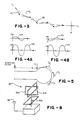
- Figures 4a and 4b are graphic illustrations of the way in which the system of Figure 1 operates;
- Figure 5 diagrammatically illustrates, in plan view, the way in which the system of Figure 1 can be used to cause its boring device to home in on a number of different target points in order to provide a specifically configured boring path;
- Figure 6 is a block diagram depicting the electronic controls of the system of Figure 1;
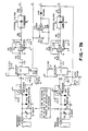
- Figures 7A, 7B, and 7C together are a detailed schematic illustration corresponding to the block diagram of Figure 6; and
- Figure 8 is a diagrammatic illustration, in perspective view, of a modified receiving arrangement which could form part of another system in accordance with the invention.
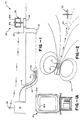
- Referring now to the drawings, Figure 1 illustrates a homing system in accordance with the invention and generally indicated by the
reference numeral 10. The system includes aboring device 12 and an assembly of other components which serve to physically move and guide the boring device through the ground from anaboveground starting point 14 to the particular in-ground target point 16 which might or might not be its final destination. These other components include acontrol station 18 atstarting point 14 and anumbilical arrangement 20 which serves to connect the boring device to the control station for physically moving the boring device as the latter steers through the ground under the control of the control station, as will be described in more detail below. - The boring device itself carries suitable means generally indicated at 22 for producing a near full electromagnetic dipole field 24 (Figure 2) containing a precontrolled homing signal. A receiving assembly which is generally indicated at 26 and which also forms part of the overall homing system is located at
ground level location 28 directly above or beyondtarget point 16. This assembly includes a specifically configured receivingantenna 30 which serves to detect the homing signal contained withindipole field 24. Other components forming part ofoverall assembly 26 respond to the detection of this homing signal to produce an internal electronic signal containing information which indicates whether the boring device is on or off a particular course line leading totarget point 16 and, if the boring device is off its course, whether its horizontal component of movement is headed to the left or right of the course line with respect to the target point. Atransmitting assembly 32, also forming part ofassembly 26, responds to this internal signal for transmitting by means of electromagnetic waves a control signal containing the same information back tocontrol station 18 where it is picked up by a cooperatingreceiving antenna 34. Components located in part atcontrol station 18 and in part onboring device 12 respond to the transmitted control signal in order to control the horizontal component of movement of the boring device as it is steered on course totarget point 16. The control station includes its own means apart from the control signal for controlling the vertical component of movement of the boring device, as the latter moves to targetpoint 16. - In European Patent Application No. 87304434.1 the boring device is shown including a series of high pressure fluid jets at its front end for boring through the soil. It is connected at its back end to an umbilical which is acted upon by a thrust assembly to physically push the boring device thorugh the soil as its fluid jets cut a path in front of it. All of the physical aspects of such boring device and the way in which it is thrust through the soil may be incorporated into
boring device 12 andcontrol station 18. - In European Patent Application No. 87304537.1 the same boring device and thrust assembly are shown along with a specific technique for steering the boring device through the ground and monitoring its orientation. More specifically, in this application there is described a particular technique for physically steering the boring device by rotating its forward fluid jets in a modulated fashion, and there are specific arrangements illustrated for monitoring the boring device's pitch and roll angles relative to given references. At the same time, the depth of the boring device, that is its vertical distance with respect to, for example, ground level, can be monitored by a conventional arrangement. One such arrangement includes a tube having one end which contains a pressure transducer while the opposite end is maintained in fluid communication with a reservoir filled with, for example, hydraulic fluid which also fills the tube itself. The end of the tube containing the pressure transducer is located in the boring device and the reservoir is placed at ground level with the tube running through the umbilical. In this way, the head pressure at the transducer resulting from the hydraulic fluid varies linearly with the vertical position of the boring device and therefore can be conventionally and suitably monitored, once calibrated, to monitor the depth of the boring device. These features may be incorporated into the system of the present invention.
- The vertical component of movement of the
boring device 12 can be controlled manually by an operator or it can be preprogrammed by means of a computer. For example, where the above ground contour betweenstarting point 14 andtarget point 16 defines a hill, the vertical component of movement of theboring device 12 can be preprogrammed so that it parallels the curvature of the aboveground contour as it moves from its starting point to its target point. Where it is necessary to phsically follow the actual location of the boring device at any given time, this can be accomplished by utilizing, for example, a locating arrangement of the type described in European Patent Application No. 87304499.4. - The way in which the horizontal component of movement of the
boring device 12 is established as it moves through the ground in order to cause it to home in ontarget point 16 will now be described with reference to Figures 2, 3, 4a and 4b of the drawings. - As indicated above, receiving
arrangement 26 includes a specifically configuredantenna arrangement 30. This arrangement includes a pair of conventional and readily providable looped antennas 30a and 30b which are placed in intersecting perpendicular planes but electrically insulated from one another. Each of these looped antennas is intended to receive only the magnetic component ofdipole field 24 and therefore includes a conventional and readily providable field for blocking out the electric component of the field. An actual working embodiment of one of these looped antennas is illustrated in Figure 1a. Note that this antenna includes about 100 turns of Litz wire and the outside of the loop is shielded by suitable metal. A small gap is provided on the shield such that the shield does not form a continuous loop. - As stated above, the
electromagnetic dipole field 24 generated fromboring device 12 includes a predetermined homing signal. This signal uses the amplitude of the field of a fixed frequency, of about 2 or 3 KHz to as high as about .5 MHz, preferably a frequency of between about 80 and 90 KHz and specifically 83.075 KHz in an actual working embodiment. Each of the looped antennas 30a and 30b is designed to pick up on to the components of field 24 (e.g., the homing signal) that is normal to the plane of its loop, and only those components, as is known in the art. This results in a pick up signal having the same frequency as the homing signal and an amplitude which depends upon the intensity of normal component of the field so picked up. - Referring specifically to Figure 2 in conjunction with Figures 1 and 4a, 4b, the antenna 30a is shown in Figures 1 and 2 in line with the desired course of
device 12 at a given point in time as the latter moves through the ground. At the same time, antenna 30b extends normal to that designed course. Antenna 30a is intended to establish the course line and, as will be seen, serves as a null antenna, while antenna 30b is intended to serve as a reference antenna. Because reference antenna 30b extends normal to the intended course ofboring device 12 and therefore generally across the flux lines generated by itsdipole field 24, antenna 30b produces a relatively strong (large amplitude) signal SB (Figures 4a, 4b) having the same frequency as the homing signal. As will be seen below, this signal is processed by circuitry forming part ofoverall receiver assembly 26, preferably including circuit means to maintain the amplitude of signal SB at a constant, readily detectable level whetherboring device 12 is on course or slightly off course and regardless of its nearness to antennas 30a, 30b. - Because the null antenna 30a is positioned parallel to the intended course of
boring device 12, when the boring device is precisely on course, there are substantially no flux lines making upfield 24 which cut through the null antenna and, absent even a horizontal component cutting through the null antenna, the latter does not generate a signal at all. However, as the boring device moves from its intended path, as established by the position of null antenna 30a, the normal component of the particular flux line will instantaneously cut through the null antenna and produce a relatively low amplitude signal SA as illustrated in Figures 4a and 4b, at the same frequency as the homing signal and therefore at the same frequency as signal SB. It should be noted from Figures 4a and 4b that the amplitude of signal SA, relatively speaking, is substantially smaller than the amplitude of signal SB. That is because the flux lines from boringdevice 12 cut through the null antenna, if they cut through at all, at a much greater angle (with respect to its normal) than they cut through the reference antenna. - Still referring to Figures 4a and 4b in conjunction with Figure 2, as stated immediately above, if boring
device 12 is on course, no null signal SA will be produced at all, that is, its amplitude will be zero. If the boring device starts to move horizontally to the left or to the right of its course line (e.g., its horizontal component), it will result in the immediate production of signal SA. If the deviation is to the left of the course line, the flux lines fromdipole field 24 will cut through null antenna 30a in one direction and if the deviation is to the right, it will cut through the antenna in the opposite direction. As a result, the corresponding null signals SA will be 180° out of phase with one another. Figure 4a shows a deviation signal to the left, for example, while Figure 4b illustrates a deviation signal in the opposite direction, for example to the right. Note that a given point in time on the reference signal SB, for example, at its peak positive amplitude, the null signal SA in Figure 4a is positive with respect to the reference signal while the signal SA in Figure 4b is negative with respect to the same point in the reference signal. In this way, the reference signal can be used in conjunction with, for example, an oscilloscope, to determine whether a particular deviation in the path taken by boringdevice 12 is to the left or right of the intended course. - The processing circuitry forming part of
overall assembly 26 processes both the reference signal and null signal (if present) and produces its own processed internal signal which indicates whether the boring device is on or off a particular course leading to the target point at that particular point in time and, if the boring device is off course, whether its horizontal component of movement is headed to the left or right of the course with respect to the target. This signal is then transmitted viaantenna 32 to receivingantenna 34 where it is picked up and used by thecontrol station 18 to control the movement ofboring device 12 in order to eliminate the null signal all together, that is, to place the boring device back on its course. Thus, as shown in Figure 3, if the boring device begins to move off to the right from its intended course (position 1) which is generally indicated by dotted lines at 36, the null signal SA (for example the one in Figure 4b) will be generated, causing the boring device to be steered back to the left (position 2). This, in turn, will eliminate the null signal corresponding to Figure 4b but might result in the boring device moving through the course line too far to the left, thereby producing the null signal SA shown in Figure 4a. Thus, in actuality, the boring device will tend to zigzag its way to the target, as shown in an exaggerated manner in Figure 3 as it moves fromposition 1 toposition 2 and so on. In theory,boring device 12 locks on a single flux line, for example, the flux line F1 shown in Figure 2, which is established by the position of null antenna 30a. So long as the boring device is not caused to move substantially from its intended course which might otherwise result from, for example, an obstruction, it will home in on flux line F1. Should it have to move substantially from flux line F1 due to an obstruction, it will eventually lock onto a different flux line and will move to the target in the same manner. - It is to be understood that the way in which boring
device 12 locks in on a flux line and homes in on its target, as described above, relates only to its horizontal component of movement. Signals SA and SB only control whether the boring device moves to its left or to its right in a horizontal plane and not up and down. As a result, the boring device can be homed in on an in-ground target point, for example,point 16 without having to locate antennas 30a and 30b at the target point. The antennas could be located aboveground as illustrated in, for example, Figure 1. At the same time, the vertical component of movement of the boring device can be simultaneously controlled by means ofcontrol station 18, either manually or through some sort of preset program through readily providable means not shown. - In order to carry out the homing procedure just described, it is only necessary to know that a null signal exists and it phase relative to the reference signal. With this information, the signal can be nulled out in the manner described above in order to maintain the boring device on course. However, it may be desirable to know how far off course in terms of heading and displacement the boring device is quantitatively. This can be determined from the same signals SA and SB. Since the amplitude of reference signal SB varies with distance (1/r³, where r is the distance from the center of field 24), the amplitude of signal SA can be readily normalized with respect to the amplitude of the reference signal in order to determine course error magnitude quantitatively. The actual circuitry involved to accomplish this forms part of the overall circuitry forming part of receiving
assembly 26, as will be discusses in conjunction with Figures 6 and 7. - Before turning to Figures 6 and 7, attention is briefly directed to Figure 5. This figure diagrammatically illustrates the way in the
system 10 can be used to move theboring device 12 along a series of paths around possible obstructions in a relatively uncomplicated manner. Figure 5 diagrammatically illustrates a cul-de-sac. The boring device is initially directed into the ground at a starting point on one side of the cul-de-sac and the receivingassembly 26 is placed aboveground at a first point T1. Usingsystem 10, the boring device is moved to a target point directly under T1. Thereafter, the receiving assembly is physically picked up and moved to a point T2 which is relatively easy since there are no hard wires associated with the receiving assembly and since the receiving assembly does not have to be buried. The boring device is then moved to the target point directly under T2. This procedure continues in order to move the boring device to T3 and finally to point T4. - Having described
overall system 10, attention is now directed to Figure 6 which is an electronic block diagram ofassembly 26 including looped antennas 30a and 30b, transmittingantenna 32 and the electronic circuitry discussed above. Figure 6 also depicts by means of block diagram the receivingantenna 34 and control circuitry forming part ofcontrol station 18 and part of the boring device. - As illustrated in Figure 6, the signal detected by reference antenna 30b passes through a tuned amplifier which serves to reduce noise and increase its amplitude. This signal is passed through a voltage controlled attenuator which forms part of an overall feedback loop including an amplitude detector and low-pass filter, all of which function as an automatic gain control to fix the amplitude to signal SB, as discussed previously. The signal passes out of the voltage controlled attenuator and through a series of crystal filters which serve to narrow its bandwidth in order to increase its signal-to-noise ratio. An adjustable phase shifter acts on the signal to adjust for any imperfections in the antenna, e.g., for purposes of calibration, and then the signal is passed through a buffer and ultimately into a lock-in amplifier, as well as back through the feedback loop including the low-pass filter and amplitude detector.
- At the same time, the null signal SA, assuming that one is present, passes through a similar tuned amplifier for reducing noise and increasing amplitude and thereafter through a voltage controlled amplifier and a series of crystal filters and thereafter into the lock-in amplifier. This latter component serves as a conventional synchronous detector so as to distinguish the relatively low amplitude null signal SA from noise by comparing it to the reference signal SB. At the same time, it serves to detect the phase of the null signal with respect to the reference signal and therefore whether the boring device has deviated to the left or right of its intended course. The output from the lock-in amplifier (which serves as the previously described internal signal) passes through a low-pass filter in order to reduce the bandwidth and eventually acts on a voltage controlled oscillator and modulator/transmitter for producing the previously described electromagnetic signal out of
antenna 32. As it may be desirable to normalize the null signal with respect to the reference signal in order to provide a quantitative value for the null signal, the signal from the output of the lock-in amplifier, after passing through the low-pass filter, is input through the normalizing network (the x divided y box) as shown in Figure 6. - The actual working circuitry associated with
assembly 26 is illustrated in Figure 7 and is readily understandable by those of ordinary skill in the art in view of the foregoing and in view of the block diagram of Figure 6 and, hence, will not be discussed herein. - Overall receiving
assembly 26 has been described as including a specifically configuredantenna arrangement 30 including two looped antennas 30a and 30b. In this way, the homing process foroverall system 10 relates only to the horizontal components of movement ofboring device 12. In Figure 8, a modified receiving assembly 26ʹ is illustrated. This assembly includes all of the same components forming part ofassembly 26, that is, antennas 30a and 30b and transmittingantenna 32 as well as the associated circuitry. In addition, assembly 26ʹ includes a second looped null antenna 30c which may be identical to antennas 30a and 30b but which is positioned orthogonal to both. Moreover, this third antenna includes associated circuitry which functions therewith in the same manner as the circuitry associated with antenna 30a, except that antenna 30c is responsible for controlling vertical deviations in the movement of the boring device from its intended path. In this way, the homing process controls both the horizontal and vertical components of movement of the boring device as it moves towards its intended target. This has the advantage that separate means for controlling the vertical component of movement of the boring device are not necessary. However, it does mean that the overall antenna configuration must coincide with the intended target point. That is, the boring device will home in on the antenna configuration itself wherever it is located.
Claims (13)
Applications Claiming Priority (2)
| Application Number | Priority Date | Filing Date | Title |
|---|---|---|---|
| US06/914,706 US4881083A (en) | 1986-10-02 | 1986-10-02 | Homing technique for an in-ground boring device |
| US914706 | 1986-10-02 |
Publications (2)
| Publication Number | Publication Date |
|---|---|
| EP0262882A2 true EP0262882A2 (en) | 1988-04-06 |
| EP0262882A3 EP0262882A3 (en) | 1989-01-25 |
Family
ID=25434685
Family Applications (1)
| Application Number | Title | Priority Date | Filing Date |
|---|---|---|---|
| EP87308523A Ceased EP0262882A3 (en) | 1986-10-02 | 1987-09-25 | Homing system for an in-ground boring device |
Country Status (5)
| Country | Link |
|---|---|
| US (1) | US4881083A (en) |
| EP (1) | EP0262882A3 (en) |
| JP (1) | JPS63165686A (en) |
| AU (1) | AU602007B2 (en) |
| DK (1) | DK519987A (en) |
Cited By (12)
| Publication number | Priority date | Publication date | Assignee | Title |
|---|---|---|---|---|
| WO1989010464A1 (en) * | 1988-04-19 | 1989-11-02 | Blis | Process and device for monitoring the advance of a drilling head in the ground |
| EP0361805A1 (en) * | 1988-09-29 | 1990-04-04 | Gas Research Institute | Percussive mole boring device with electronic transmitter |
| EP0377153A2 (en) * | 1989-01-04 | 1990-07-11 | Schmidt, Paul, Dipl.-Ing. | Boring ram |
| WO1990015221A1 (en) * | 1989-06-09 | 1990-12-13 | British Gas Plc | Moling system |
| WO1991012987A1 (en) * | 1990-03-02 | 1991-09-05 | Desinsectisation Moderne | Self propelled probe, particularly for penetrating a powdered material |
| FR2659112A1 (en) * | 1990-03-02 | 1991-09-06 | Desinsectisation Moderne | Borer for penetrating and moving in a mass of pulverulent material |
| US5065098A (en) * | 1990-06-18 | 1991-11-12 | The Charles Machine Works, Inc. | System for locating concealed underground objects using digital filtering |
| US5264795A (en) * | 1990-06-18 | 1993-11-23 | The Charles Machine Works, Inc. | System transmitting and receiving digital and analog information for use in locating concealed conductors |
| WO1997020164A1 (en) * | 1995-11-28 | 1997-06-05 | Werner Gebauer | Method and device for renovating underground pipelines, and use |
| US5907242A (en) * | 1995-05-15 | 1999-05-25 | The Charles Machine Works, Inc. | Balanced passive bandpass filter and preamplifier for a receiver |
| GB2338557A (en) * | 1998-06-15 | 1999-12-22 | Radiodetection Ltd | Detecting underground objects |
| WO2007024779A1 (en) | 2005-08-23 | 2007-03-01 | The Charles Machine Works, Inc. | System for tracking and maintaining an on-grade horizontal borehole |
Families Citing this family (39)
| Publication number | Priority date | Publication date | Assignee | Title |
|---|---|---|---|---|
| DE68909355T2 (en) * | 1988-09-02 | 1994-03-31 | British Gas Plc | Device for controlling the position of a self-propelled drilling tool. |
| FR2665215B1 (en) * | 1990-07-27 | 1997-12-26 | Elf Aquitaine | DYNAMOMETRIC MEASUREMENT ASSEMBLY FOR DRILLING ROD PROVIDED WITH RADIO TRANSMISSION MEANS. |
| US6417666B1 (en) * | 1991-03-01 | 2002-07-09 | Digital Control, Inc. | Boring tool tracking system and method using magnetic locating signal and wire-in-pipe data |
| US5337002A (en) | 1991-03-01 | 1994-08-09 | Mercer John E | Locator device for continuously locating a dipole magnetic field transmitter and its method of operation |
| US5320180A (en) * | 1992-10-08 | 1994-06-14 | Sharewell Inc. | Dual antenna radio frequency locating apparatus and method |
| US5469155A (en) * | 1993-01-27 | 1995-11-21 | Mclaughlin Manufacturing Company, Inc. | Wireless remote boring apparatus guidance system |
| US5515931A (en) * | 1994-11-15 | 1996-05-14 | Vector Magnetics, Inc. | Single-wire guidance system for drilling boreholes |
| US5621325A (en) * | 1995-05-16 | 1997-04-15 | The Charles Machine Works, Inc. | Avoiding ghosting artifacts during surface location of subsurface transmitters |
| US5585726A (en) * | 1995-05-26 | 1996-12-17 | Utilx Corporation | Electronic guidance system and method for locating a discrete in-ground boring device |
| US5726359A (en) * | 1995-11-29 | 1998-03-10 | Digital Control, Inc. | Orientation sensor especially suitable for use in an underground boring device |
| US5720354A (en) * | 1996-01-11 | 1998-02-24 | Vermeer Manufacturing Company | Trenchless underground boring system with boring tool location |
| US5711381A (en) * | 1996-01-16 | 1998-01-27 | Mclaughlin Manufacturing Company, Inc. | Bore location system having mapping capability |
| US6191585B1 (en) * | 1996-05-03 | 2001-02-20 | Digital Control, Inc. | Tracking the positional relationship between a boring tool and one or more buried lines using a composite magnetic signal |
| US5757190A (en) * | 1996-05-03 | 1998-05-26 | Digital Control Corporation | System including an arrangement for tracking the positional relationship between a boring tool and one or more buried lines and method |
| AUPO062296A0 (en) * | 1996-06-25 | 1996-07-18 | Gray, Ian | A system for directional control of drilling |
| US5878825A (en) * | 1996-07-03 | 1999-03-09 | Kubota Corporation | Underground propelling method |
| US6427784B1 (en) | 1997-01-16 | 2002-08-06 | Mclaughlin Manufacturing Company, Inc. | Bore location system having mapping capability |
| GB9704181D0 (en) * | 1997-02-28 | 1997-04-16 | Thompson James | Apparatus and method for installation of ducts |
| US6250402B1 (en) * | 1997-04-16 | 2001-06-26 | Digital Control Incorporated | Establishing positions of locating field detectors and path mappings in underground boring tool applications |
| US6079506A (en) * | 1998-04-27 | 2000-06-27 | Digital Control Incorporated | Boring tool control using remote locator |
| US6215888B1 (en) * | 1998-06-10 | 2001-04-10 | At&T Corp. | Cable location method and apparatus using modeling data |
| US6367564B1 (en) * | 1999-09-24 | 2002-04-09 | Vermeer Manufacturing Company | Apparatus and method for providing electrical transmission of power and signals in a directional drilling apparatus |
| WO2001046554A1 (en) * | 1999-12-21 | 2001-06-28 | Utilx Corporation | Long range electronic guidance system for locating a discrete in-ground boring device |
| US6543550B2 (en) | 2000-01-31 | 2003-04-08 | Utilx Corporation | Long range electronic guidance system for locating a discrete in-ground boring device |
| US6688408B2 (en) | 2000-05-16 | 2004-02-10 | James S. Barbera | Auger drill directional control system |
| WO2002006633A1 (en) * | 2000-07-18 | 2002-01-24 | The Charles Machine Works, Inc. | Remote control for a drilling machine |
| US6871712B2 (en) | 2001-07-18 | 2005-03-29 | The Charles Machine Works, Inc. | Remote control for a drilling machine |
| US6496008B1 (en) | 2000-08-17 | 2002-12-17 | Digital Control Incorporated | Flux plane locating in an underground drilling system |
| US6717410B2 (en) * | 2000-09-08 | 2004-04-06 | Merlin Technology, Inc. | Bore location system |
| US7218244B2 (en) | 2001-09-25 | 2007-05-15 | Vermeer Manufacturing Company | Common interface architecture for horizontal directional drilling machines and walk-over guidance systems |
| US6727704B2 (en) * | 2001-11-20 | 2004-04-27 | Marlin Technology, Inc. | Boring tool tracking/guiding system and method with unconstrained target location geometry |
| US6854535B1 (en) * | 2002-12-03 | 2005-02-15 | Merlin Technology, Inc. | Bore location system and method of calibration |
| US6776246B1 (en) | 2002-12-11 | 2004-08-17 | The Charles Machine Works, Inc. | Apparatus and method for simultaneously locating a fixed object and tracking a beacon |
| US7201236B1 (en) | 2002-12-11 | 2007-04-10 | The Charles Machine Works, Inc. | Apparatus and method for tracking multiple signal emitting objects |
| US7150331B2 (en) * | 2003-06-17 | 2006-12-19 | The Charles Machine Works, Inc. | System and method for tracking and communicating with a boring tool |
| US7372276B2 (en) * | 2005-02-16 | 2008-05-13 | Goldak, Inc. | Digital locating system and device for underground object detection |
| CA2606627C (en) * | 2005-05-10 | 2010-08-31 | Baker Hughes Incorporated | Bidirectional telemetry apparatus and methods for wellbore operations |
| US7861424B2 (en) * | 2006-11-13 | 2011-01-04 | Robert Bosch Tool Corporation | Pipe laser |
| US8381836B2 (en) | 2010-01-19 | 2013-02-26 | Merlin Technology Inc. | Advanced underground homing system, apparatus and method |
Citations (5)
| Publication number | Priority date | Publication date | Assignee | Title |
|---|---|---|---|---|
| US3529682A (en) * | 1968-10-03 | 1970-09-22 | Bell Telephone Labor Inc | Location detection and guidance systems for burrowing device |
| US3589454A (en) * | 1968-12-27 | 1971-06-29 | Bell Telephone Labor Inc | Mole guidance system |
| US3731752A (en) * | 1971-06-25 | 1973-05-08 | Kalium Chemicals Ltd | Magnetic detection and magnetometer system therefor |
| US3907045A (en) * | 1973-11-30 | 1975-09-23 | Continental Oil Co | Guidance system for a horizontal drilling apparatus |
| DE3306405A1 (en) * | 1983-02-24 | 1984-08-30 | Manfred 2305 Heikendorf Schmidt | Method and apparatus for laying piping systems in the ground |
Family Cites Families (6)
| Publication number | Priority date | Publication date | Assignee | Title |
|---|---|---|---|---|
| US2291450A (en) * | 1939-12-28 | 1942-07-28 | Hazeltine Corp | Antenna system |
| US2908863A (en) * | 1955-02-18 | 1959-10-13 | Robert J Neff | Electronic locator |
| US3900878A (en) * | 1973-02-14 | 1975-08-19 | Raytheon Co | Mine rescue system |
| US4403664A (en) * | 1980-08-28 | 1983-09-13 | Richard Sullinger | Earth boring machine and method |
| US4710708A (en) * | 1981-04-27 | 1987-12-01 | Develco | Method and apparatus employing received independent magnetic field components of a transmitted alternating magnetic field for determining location |
| US4646277A (en) * | 1985-04-12 | 1987-02-24 | Gas Research Institute | Control for guiding a boring tool |
-
1986
- 1986-10-02 US US06/914,706 patent/US4881083A/en not_active Expired - Lifetime
-
1987
- 1987-09-25 EP EP87308523A patent/EP0262882A3/en not_active Ceased
- 1987-09-29 AU AU79076/87A patent/AU602007B2/en not_active Ceased
- 1987-10-02 DK DK519987A patent/DK519987A/en not_active Application Discontinuation
- 1987-10-02 JP JP62249650A patent/JPS63165686A/en active Pending
Patent Citations (5)
| Publication number | Priority date | Publication date | Assignee | Title |
|---|---|---|---|---|
| US3529682A (en) * | 1968-10-03 | 1970-09-22 | Bell Telephone Labor Inc | Location detection and guidance systems for burrowing device |
| US3589454A (en) * | 1968-12-27 | 1971-06-29 | Bell Telephone Labor Inc | Mole guidance system |
| US3731752A (en) * | 1971-06-25 | 1973-05-08 | Kalium Chemicals Ltd | Magnetic detection and magnetometer system therefor |
| US3907045A (en) * | 1973-11-30 | 1975-09-23 | Continental Oil Co | Guidance system for a horizontal drilling apparatus |
| DE3306405A1 (en) * | 1983-02-24 | 1984-08-30 | Manfred 2305 Heikendorf Schmidt | Method and apparatus for laying piping systems in the ground |
Cited By (19)
| Publication number | Priority date | Publication date | Assignee | Title |
|---|---|---|---|---|
| WO1989010464A1 (en) * | 1988-04-19 | 1989-11-02 | Blis | Process and device for monitoring the advance of a drilling head in the ground |
| EP0343140A2 (en) * | 1988-04-19 | 1989-11-23 | "Blis" | Method and device for surveying the progression of a drilling head in the ground |
| EP0343140A3 (en) * | 1988-04-19 | 1989-12-20 | "Blis" | Method and device for surveying the progression of a drilling head in the ground |
| EP0361805A1 (en) * | 1988-09-29 | 1990-04-04 | Gas Research Institute | Percussive mole boring device with electronic transmitter |
| EP0377153A2 (en) * | 1989-01-04 | 1990-07-11 | Schmidt, Paul, Dipl.-Ing. | Boring ram |
| EP0377153A3 (en) * | 1989-01-04 | 1991-01-16 | Schmidt, Paul, Dipl.-Ing. | Boring ram |
| WO1990015221A1 (en) * | 1989-06-09 | 1990-12-13 | British Gas Plc | Moling system |
| US5182516A (en) * | 1989-06-09 | 1993-01-26 | British Gas Plc | Moling system including transmitter-carrying mole for detecting and displaying the roll angle of the mole |
| FR2659112A1 (en) * | 1990-03-02 | 1991-09-06 | Desinsectisation Moderne | Borer for penetrating and moving in a mass of pulverulent material |
| WO1991012987A1 (en) * | 1990-03-02 | 1991-09-05 | Desinsectisation Moderne | Self propelled probe, particularly for penetrating a powdered material |
| US5377551A (en) * | 1990-03-02 | 1995-01-03 | Desinsectisation Moderne | Probe for penetrating and displacing particularly into a mass of pulverulent material |
| US5065098A (en) * | 1990-06-18 | 1991-11-12 | The Charles Machine Works, Inc. | System for locating concealed underground objects using digital filtering |
| US5264795A (en) * | 1990-06-18 | 1993-11-23 | The Charles Machine Works, Inc. | System transmitting and receiving digital and analog information for use in locating concealed conductors |
| US5907242A (en) * | 1995-05-15 | 1999-05-25 | The Charles Machine Works, Inc. | Balanced passive bandpass filter and preamplifier for a receiver |
| WO1997020164A1 (en) * | 1995-11-28 | 1997-06-05 | Werner Gebauer | Method and device for renovating underground pipelines, and use |
| GB2338557A (en) * | 1998-06-15 | 1999-12-22 | Radiodetection Ltd | Detecting underground objects |
| US6552548B1 (en) | 1998-06-15 | 2003-04-22 | Radiodetection Limited | Detecting underground objects |
| GB2338557B (en) * | 1998-06-15 | 2003-05-07 | Radiodetection Ltd | Detecting underground objects |
| WO2007024779A1 (en) | 2005-08-23 | 2007-03-01 | The Charles Machine Works, Inc. | System for tracking and maintaining an on-grade horizontal borehole |
Also Published As
| Publication number | Publication date |
|---|---|
| DK519987D0 (en) | 1987-10-02 |
| US4881083A (en) | 1989-11-14 |
| AU7907687A (en) | 1988-04-14 |
| DK519987A (en) | 1988-04-03 |
| JPS63165686A (en) | 1988-07-08 |
| AU602007B2 (en) | 1990-09-27 |
| EP0262882A3 (en) | 1989-01-25 |
Similar Documents
| Publication | Publication Date | Title |
|---|---|---|
| US4881083A (en) | Homing technique for an in-ground boring device | |
| EP0836667B1 (en) | Locating a discrete in-ground boring device | |
| US11035218B2 (en) | Advanced steering tool system, method and apparatus | |
| US6920943B2 (en) | Mapping tool for tracking and/or guiding an underground boring tool | |
| US4119908A (en) | Method for locating buried markers which are disposed along the path of an underground conductor | |
| US5235285A (en) | Well logging apparatus having toroidal induction antenna for measuring, while drilling, resistivity of earth formations | |
| EP0792407B1 (en) | Single-wire guidance system for drilling boreholes | |
| US7309990B2 (en) | Flux orientation locating in a drilling system | |
| JP2522474B2 (en) | Device and method for identifying the position of an independent underground excavator | |
| US7013990B1 (en) | Apparatus and method for simultaneously locating a fixed object and tracking a beacon | |
| US20110101985A1 (en) | Tracking the positional relationship between a boring tool and one or more buried lines using a composite magnetic signal | |
| US5914602A (en) | System including an arrangement for tracking the positional relationship between a boring tool and one or more buried lines and method | |
| US4626785A (en) | Focused very high frequency induction logging | |
| JP3063027B2 (en) | Position detection method | |
| JPH0436464Y2 (en) | ||
| WO2001046554A1 (en) | Long range electronic guidance system for locating a discrete in-ground boring device |
Legal Events
| Date | Code | Title | Description |
|---|---|---|---|
| PUAI | Public reference made under article 153(3) epc to a published international application that has entered the european phase |
Free format text: ORIGINAL CODE: 0009012 |
|
| AK | Designated contracting states |
Kind code of ref document: A2 Designated state(s): CH DE ES FR GB GR IT LI NL SE |
|
| PUAL | Search report despatched |
Free format text: ORIGINAL CODE: 0009013 |
|
| AK | Designated contracting states |
Kind code of ref document: A3 Designated state(s): CH DE ES FR GB GR IT LI NL SE |
|
| 17P | Request for examination filed |
Effective date: 19890630 |
|
| 17Q | First examination report despatched |
Effective date: 19900827 |
|
| RAP1 | Party data changed (applicant data changed or rights of an application transferred) |
Owner name: UTILX CORPORATION |
|
| STAA | Information on the status of an ep patent application or granted ep patent |
Free format text: STATUS: THE APPLICATION HAS BEEN REFUSED |
|
| 18R | Application refused |
Effective date: 19931017 |
|
| RIN1 | Information on inventor provided before grant (corrected) |
Inventor name: MERCER, JOHN E. Inventor name: CHAU, ALBERT W. |