EP0264956A2 - An optical code reading device - Google Patents
An optical code reading device Download PDFInfo
- Publication number
- EP0264956A2 EP0264956A2 EP87115598A EP87115598A EP0264956A2 EP 0264956 A2 EP0264956 A2 EP 0264956A2 EP 87115598 A EP87115598 A EP 87115598A EP 87115598 A EP87115598 A EP 87115598A EP 0264956 A2 EP0264956 A2 EP 0264956A2
- Authority
- EP
- European Patent Office
- Prior art keywords
- light
- reading
- light source
- optical fiber
- reading device
- Prior art date
- Legal status (The legal status is an assumption and is not a legal conclusion. Google has not performed a legal analysis and makes no representation as to the accuracy of the status listed.)
- Granted
Links
Images


Classifications
-
- G—PHYSICS
- G06—COMPUTING; CALCULATING OR COUNTING
- G06K—GRAPHICAL DATA READING; PRESENTATION OF DATA; RECORD CARRIERS; HANDLING RECORD CARRIERS
- G06K7/00—Methods or arrangements for sensing record carriers, e.g. for reading patterns
- G06K7/10—Methods or arrangements for sensing record carriers, e.g. for reading patterns by electromagnetic radiation, e.g. optical sensing; by corpuscular radiation
- G06K7/10544—Methods or arrangements for sensing record carriers, e.g. for reading patterns by electromagnetic radiation, e.g. optical sensing; by corpuscular radiation by scanning of the records by radiation in the optical part of the electromagnetic spectrum
- G06K7/10712—Fixed beam scanning
- G06K7/10762—Relative movement
-
- G—PHYSICS
- G06—COMPUTING; CALCULATING OR COUNTING
- G06K—GRAPHICAL DATA READING; PRESENTATION OF DATA; RECORD CARRIERS; HANDLING RECORD CARRIERS
- G06K2207/00—Other aspects
- G06K2207/1011—Aiming
Definitions
- the present invention relates to an optical code reading device. More specifically, the present invention provides an optical code reading device using one or more optical fibers for transmitting light from a light source to a scanning head of the device.
- the handy scanner comprises a housing of a predetermined shape suitable for holding by a hand, a light source for illuminating an object to be read, an optical system for receiving reflection light reflected from the object and for forming an image of the object, a sensor for converting the optical image obtained by the optical signal into an electrical signal and a circuit arrangement for processing the electric signal from the sensor to produce a digital signal in a binary form or binary decimal form.
- a one dimensional image sensor or two dimensional image sensor may be used as the sensor a one dimensional image sensor or two dimensional image sensor may be used.
- the use of two dimension image sensor enables to read the object of two dimension in an instant.
- the object is read by scanning sequentially in a direction of the array of the photo sensor cells of the image sensor.
- the scanning in the direction of the array of the photo sensor cells is referred to as a main scanning.
- the scanner In order to read the object, the scanner is moved in a direction perpendicular to the main scanning direction, so that the two dimensional object can be read.
- the image sensor having one dimension or two dimension is used as the sensor of the code reading device, the resolution of reading the object depends on the size of the unit photo sensor cells.
- an incadescent lamp is used as the light source and the light is dispersed.
- the light source can be deemed as a surface light source.
- the scanner may be moved in one dimension or two dimensions to obtain the image information of the object. By measuring the amount of the movement of the scanner, the point corresponding to the photo diode output can be identified.
- the photo diode In case the photo diode is used as the sensor, it is impossible to obtain the image information of the object at two points simultaneously but is possible to obtain the image information of the object only one point simultaneously. In this arrangement, it is necessary to concentratedly illuminate the light beam on one point of the object with the remainder of the object unilluminated so as to detect the reflection light only from the point new illuminated by the photo diode.
- the diameter of the light beam defines the resolution of reading the code. Therefore, it is important to illuminate the object reducing the spot size of the light beam as small as possible.
- the light projected from a light source is directly concentrated by a lens system so that the spot size is throttled and the throttled light is projected directly to the object.
- the light projected on the object is reflected and the reflected light is received by the photo diode which generates the information of the intensity of the reflected light. Since a portion of the object which is not illuminated does not generate reflection light, no effect is revealed on the output of the photo diode with respect to any pattern on that portion.
- the resolution of reading of the object is decided by the spot size of the illumination light, therefore, it is desired that the spot size is as small as possible.
- the spot size of the light projected from the light is more or less wide and in many case, the shape of the spot of the light is not a true circle but is deformed from the true circle. Therefore, even if the projected light is concentrated by the lens system, it is difficult to throttle the light into a desirably fine beam. Accordingly, the resolution of reading the object in the reading device can not be improved.
- the scanning head of the conventional code reading device is provided with a light source and a rotatable mirror to direct the light beam of the light source toward a light projection window of the scanning head so that the light beam can be projected from the window to scan the object.
- the conventional arrangement mentioned above must provide the rotational mirror in the scan head as a part of the optical system. Moreover, if the rotational mirror collects moisture or foreign matters, the reflection light from the mirror is reduced. In addition, according to the distribution of the stain of the mirror, the light intensity of the mirror is changed, whereby it becomes impossible to identify the object code and an error of reading may occur.
- the mirror and light source are provided in the scanning head, it is difficult to reduce the weight and size of the scanning head.
- the reading light in case a semiconductor laser is used for the reading light, since the reading light is infra red wave with the wave length less than 750 nm which is invisible to the human eyes.
- a gas laser such as Ar laser or He-Ne laser is used as the light source, since the spot size of the light is very small, it is difficult to see the light beam.
- auxiliary light or sighting light ⁇ In this case, in order to facilitate to see the reading light (defined as reading ⁇ ), there is proposed to attach an auxiliary light or sighting light ⁇ .
- two light sources of the light ⁇ and ⁇ are disposed in a rectangular relation and both lights are combined using a half mirror.
- employment the half mirror in the path of the reading light ⁇ causes the intensity of the reading light to be decreased and spot size of the reading light at the object to be read is expanded and the resolution is decreased.
- employment of the half mirror in the scanning head causes the scanning head bulky.
- an adjustment between the axes of the reading light and sighting light is required.
- An essential object of the present invention is to provide an optical code reading device having a high reading resolution.
- Another object of the present invention is to provide an optical code reading device having a good resistance against the atmosphere with a scanning head the weight and size of which can be reduced.
- a still further object of the present invention is to provide an optical code reading device in which the size and weight of a scanning head can be reduced.
- a still further object of the present invention is to provide a scanning head for use in an optical code reading device which is light in weight and small in size and resolution of reading object is high.
- an optical code reading device which comprises a light source for emitting reading light for illuminating an object to be read, at least one optical fiber for transferring the reading light from the light source having its one end positioned to receive the reading light from the light source, a lens system disposed to receive the reading light project from the other end of the optical fiber and to project the reading light toward the object, light detecting means for receiving the light reflected from the object to generate electric signals representing intensity of the reflected light and processing means for processing the electric signal to generate electric signal representing the object.
- a scanning head 1 comprises a housing 1a made of a generally an L character shape and is movable in one dimension or two dimensions in parallel with a surface of an object 6 to be read.
- a floor type unit 2 secured on a suitable floor or the like is provided with a light source and data processing circuit. It is noted that conventionally the light source is provided in the scanning head, but in the preferred embodiment of the present invention, the light source is provided in the floor type unit 2.
- the light source 3 As the light source 3, a semiconductor laser is used.
- the light emitted from the light source 3 is throttled by a lens 11.
- the light thus throttled is applied to an entrance unit 12 of a single mode optical fiber 4.
- the single mode optical fiber means such an optical fiber that allows to pass only the 0 dimensional mode light of the incident light with the wave length A.
- the diameter of the core is extremely small. Therefore, it is necessary to use the coupling lens 11 so that the light of the light source can be entered in the optical fiber core as many as possible.
- To use the coupling lens is a known technology.
- the semiconductor laser is small in size and the life is long enough, and is suitable as the light source.
- any other types such as He-Ne laser, Ar laser may be used except that the color of light is limited.
- He-Ne laser may be suitable since He- Ne laser has a good directionality and is inexpensive and the light therefrom is visible.
- Ar laser may be used as the light source.
- a calculation unit 9 is provided in the floor type unit 2.
- the signal mode optical fiber 4 for transferring the light from the light source and a communication cable 8 connected to the calculation unit 9 are covered by a common sheath 10. Both ends of the optical fiber 4 and communication cable 8 are connected to a terminal 16 of the scanning head 1.
- the scanning head 1 there are provided an end portion of the single mode optical fiber 4 and a lens 5 for collecting the light from the optical fiber 4.
- the light projecting end 13 of the single mode optical fiber 4 is covered with a sleeve made of metal or the like and secured in the scanning head 1 by means of a securing member (not shown).
- the light collected by the lens 5 is projected outside through a window 15 toward a point P of the object 6 to be read.
- a photo diode 7 is provided inside the window 15 of the scanning head 1 for receiving light reflected from the point P, thereby to produce an electric signal representing the intensity of the reflected light.
- the electric signal of the photo diode 7 is transferred to the calculation unit 9 in the floor type unit 2 through the communication cable 8.
- the calculation unit 9 processes the electric signals fed from the photo diode 7 so as to produce electric signals representing the object code in a known manner.
- the light emitted from the light source 1 is entered in the single mode optical fiber 4 and the light is closed in the optical fiber core of a small size.
- the light projected from the end of the single mode optical fiber 4 is throttled by the lens 5, whereby the light beam can be throttled into a small diameter.
- the shape of the light spot of the light beam projected from the single mode optical fiber 4 is also a true circle shape, and the spot size of the light beam can be reduced by the lens 5.
- the single mode optical fiber 4 is used so as to collect the light into a small area and to obtain the projected light beam pattern of a true circle shape.
- the size and weight of the scanning head 1 can be reduced up to such a size that the scanning head is placed on a human palm.
- light beam Due to the diffraction of light, light beam has a finite spot size.
- the spot size of the light at respective points further than the point at which the minimum spot size is obtained is expanded.
- Z axis is defined in the direction of the light progression.
- ⁇ is the wave length of light.
- the radius of the light beam increases proportional to the square of the distance from the end of the single mode optical fiber 4.
- the point G near the lens 5 is called a near critical point.
- the point H far from the lens 5 is called a far critical point.
- the beam sizes W(G) and W(H) are the function of the minimum beam radius F which can be selected as desired.
- the value F for obtaining the minimum beam radius at the critical points G and H can be calculated by the following calculation by defining the value F as an independent variable.
- the value a can be obtained by the equation Since the value b is preliminarily given and the value a can be obtained by the equation (8), the focal point f of the lens 5 can be calculated
- An example of the device according to the present invention was provided using a single mode optical fiber of which radius E is 2.4 ⁇ m.
- the standard point b was 250 mm
- near critical point G was 200 mm
- the wave length ⁇ of the light was 0.75 ⁇ m and ⁇ was 50mm.
- the beam radius Fm was 109 ⁇ m and the beam radius W(G) of the near critical point was 154 ⁇ m.
- the value a was 5.58 mm and the focal length of the lens was 5.46 mm according to the value b was 250 mm.
- the spot size of the light at the near critical point is 154 ⁇ m radius can be obtained.
- the light to be projected to the object is passed the single mode optical fiber 4 and in turn the lens 5, so that the light beam can be throttled and the beam size is reduced enough keeping the spot shape in a true circle even if the point at which the light beam is projected is departed away from the window 15 of the scanning head 1, whereby a high reading resolution of the object can be obtained.
- the scanning head shown in the present embodiment is suitable for hand scanner for code reading device.
- FIG. 3 showing another preferred embodiment of the present invention, wherein the light projecting end 13 and the lens 5 are mounted on a rotation mechanism 14 which is reciprocally rotatable around a rotation axis 17 in one plane (in a horizontal plane) by a predetermined angle range so that the the light projecting end 13 and lens 5 also can rotate and the light beam projected from the lens 5 can be moved along a scanning direction which is perpendicular to the axis of the lens 5.
- the rotation mechanism 14 is driven to rotate as mentioned above by a driving mechanism (not shown) which is provided in the housing of the scanning head 1.
- the power source for an electric motor (not shown) of the driving mechanism may be accommodated in the floor unit 2 and the power for the electric motor is transferred to the scanning unit 1 by means of a suitable cable (not shown) Such cable may be covered with the optical fibers 4 and 6 in the sheath 10.
- the rotation mechanism 14 By rotating the rotation mechanism 14 reciprocally in a predetermined angle range, the direction of the light projected from the lens 5 is changed along the scanning direction and the object 6 can be scanned in a direction perpendicular to the lens axis, so that the detection point P can be changed time to time, whereby the light reflected from the code or character on the object 6 can be consecutively detected by the photo diode 7.
- the rotation mechanism mounts only light weight elements such as the lens 5 and the light projecting end 13 of the single mode optical fiber 4, it is possible to make the rotation mechanism simple.
- the reflection mirror is not provided in the scanning head, the problem of stain of the mirror can be eliminated and the scanning head can be used under a bad atmosphere.
- an LED 17 (light emitting diode) as an additional light source for emitting visible light.
- the light emitted from the LED 17 is used to sight the light beam of the laser 3 on the object and therefore the light of the LED 17 is referred to as a sighting light hereinafter.
- the spot size of the sighting light is not necessarily to be fine, and various colors of LEDs are available in the market, therefore, LED is used as the source of the sighting light.
- an incadscent lamp may be used as the sighting light source.
- the light from the light source 3 is pulse modulated, while the light from the LED 17 is a D.C. light.
- a collimating lens 18 in front of the LED 17 to collimate the light from the LED 17 and a plural number of optical fibers 16 of a multi mode type each provided with a light input end 22 in the form of a cylindrical sleeve made of metal.
- optical fibers 16 of a multi mode type each provided with a light input end 22 in the form of a cylindrical sleeve made of metal.
- four optical fibers are used and the cross sectional view thereof is shown in Fig. 5.
- optical fiber for transferring the light of LED.
- a plurality of optical fibers may be used so that a large amount of light can be transferred to the scanning head as many as possible.
- optical fibers of the single mode type There may be used one or more optical fibers of the single mode type. However, preferably the multi mode type optical fiber is used so that a large amount of light can be transferred to the scanning head as many as possible.
- the light of the LED 17 is collimated by the collimating lens 18 and the collimated light is applied to the light input ends 22 of the four multi mode optical fibers 116.
- the four multi mode optical fibers 16 and the single mode optical fiber 4 as well as the communication cable 8 are covered by the sheath 10 and coupled to the scanning head 1 through an end terminal 26.
- the multi mode optical fibers 16 are ended at output ends 23 made of sleeve and arranged in a manner as shown in Fig. 6. As shown in Fig. 6, the multi mode optical fibers 16 and the sleeves or output ends 23 are disposed around the peripheral portions of the sleeve 13 of the single mode optical fiber 4.
- the number of the output ends 23 is equal to the number of the multi mode optical fibers 16.
- the beams of the sighting light ⁇ projected from the output ends or sleeves 23 are throttled by a lens 5 as well as the light ⁇ of reading the object from the single mode optical fiber 4. Both of light beams ⁇ and ⁇ are projected on the object 6 through the window 15.
- the output ends 13 and 23 are arranged similar to a coaxial manner, the light axis of the sighting light ⁇ and that of the light ⁇ for reading the object coincide without light axis adjustment.
- the reading light ⁇ is projected on the object 6 with a small spot size and the sighting light ⁇ is projected on the object 6 with relatively large spot size surrounding the spot of the reading light so as to facilitate to see the scanning point P at which the reading light ⁇ is projected.
- the light reflected from the scanning point P is received by the photo diode 7 and the intensity of the reflected light corresponds to the brightness and darkness of the scanning point or code to be read whereby the degree of the brightness and darkness of the scanning point P can be detected by the output of the photo diode 7.
- the output of the photo diode 7 is fed to the calculation unit 9 in the floor type unit 2 through the communication cable 8.
- the reflected light contains reading light ⁇ and sighting light ⁇ .
- the reading light ⁇ is pulse modulated, by taking the pulse modulated component in the output of the photo diode 17 by the calculation unit 9, the component of the sighting light ⁇ can be detected and the code or character of the object can be read.
- the detecting point P to which the reading light is projected is illuminated by the sighting light ⁇ , the detecting point can be easily seen, whereby scanning operation of the scanning head is easy.
- the scanning head can be made small in size and light in weight and the structure of the scanning head becomes simple. Moreover, adjustment of light axes of the reading light ⁇ and the sighting light ⁇ is unnecessary, the scanning head can manufactured easily.
Abstract
Description
- The present invention relates to an optical code reading device. More specifically, the present invention provides an optical code reading device using one or more optical fibers for transmitting light from a light source to a scanning head of the device.
- There have been used code reading devices of handy scanner type for reading characters and various kinds of code such as bar codes.
- The handy scanner comprises a housing of a predetermined shape suitable for holding by a hand, a light source for illuminating an object to be read, an optical system for receiving reflection light reflected from the object and for forming an image of the object, a sensor for converting the optical image obtained by the optical signal into an electrical signal and a circuit arrangement for processing the electric signal from the sensor to produce a digital signal in a binary form or binary decimal form. As the sensor a one dimensional image sensor or two dimensional image sensor may be used. The use of two dimension image sensor enables to read the object of two dimension in an instant. When a one dimensional image sensor is used, the object is read by scanning sequentially in a direction of the array of the photo sensor cells of the image sensor. The scanning in the direction of the array of the photo sensor cells is referred to as a main scanning. In order to read the object, the scanner is moved in a direction perpendicular to the main scanning direction, so that the two dimensional object can be read. In case the image sensor having one dimension or two dimension is used as the sensor of the code reading device, the resolution of reading the object depends on the size of the unit photo sensor cells. Moreover, since it is required to illuminate a region expanding in one dimension or two dimensions when the sensor of one dimension or two dimension image sensor is used, an incadescent lamp is used as the light source and the light is dispersed. Thus the light source can be deemed as a surface light source.
- As the sensor for reading the object code, there may be used a photo diode. In this case the scanner may be moved in one dimension or two dimensions to obtain the image information of the object. By measuring the amount of the movement of the scanner, the point corresponding to the photo diode output can be identified.
- In case the photo diode is used as the sensor, it is impossible to obtain the image information of the object at two points simultaneously but is possible to obtain the image information of the object only one point simultaneously. In this arrangement, it is necessary to concentratedly illuminate the light beam on one point of the object with the remainder of the object unilluminated so as to detect the reflection light only from the point new illuminated by the photo diode. The diameter of the light beam defines the resolution of reading the code. Therefore, it is important to illuminate the object reducing the spot size of the light beam as small as possible.
- In the conventional code reading device using the photo diode as the sensor, the light projected from a light source is directly concentrated by a lens system so that the spot size is throttled and the throttled light is projected directly to the object.
- The light projected on the object is reflected and the reflected light is received by the photo diode which generates the information of the intensity of the reflected light. Since a portion of the object which is not illuminated does not generate reflection light, no effect is revealed on the output of the photo diode with respect to any pattern on that portion.
- As mentioned above, the resolution of reading of the object is decided by the spot size of the illumination light, therefore, it is desired that the spot size is as small as possible.
- The spot size of the light projected from the light is more or less wide and in many case, the shape of the spot of the light is not a true circle but is deformed from the true circle. Therefore, even if the projected light is concentrated by the lens system, it is difficult to throttle the light into a desirably fine beam. Accordingly, the resolution of reading the object in the reading device can not be improved.
- Moreover, the scanning head of the conventional code reading device is provided with a light source and a rotatable mirror to direct the light beam of the light source toward a light projection window of the scanning head so that the light beam can be projected from the window to scan the object.
- The conventional arrangement mentioned above must provide the rotational mirror in the scan head as a part of the optical system. Moreover, if the rotational mirror collects moisture or foreign matters, the reflection light from the mirror is reduced. In addition, according to the distribution of the stain of the mirror, the light intensity of the mirror is changed, whereby it becomes impossible to identify the object code and an error of reading may occur.
- Moreover, since the mirror and light source are provided in the scanning head, it is difficult to reduce the weight and size of the scanning head.
- Moreover, in the conventional code reading device, in case a semiconductor laser is used for the reading light, since the reading light is infra red wave with the wave length less than 750 nm which is invisible to the human eyes. In case a gas laser such as Ar laser or He-Ne laser is used as the light source, since the spot size of the light is very small, it is difficult to see the light beam.
- In this case, in order to facilitate to see the reading light (defined as reading Σ), there is proposed to attach an auxiliary light or sighting light Π. In this arrangement, in the prior art, two light sources of the light Σand Π are disposed in a rectangular relation and both lights are combined using a half mirror. However, employment the half mirror in the path of the reading light Σ causes the intensity of the reading light to be decreased and spot size of the reading light at the object to be read is expanded and the resolution is decreased. Moreover, employment of the half mirror in the scanning head causes the scanning head bulky. Moreover, an adjustment between the axes of the reading light and sighting light is required.
- An essential object of the present invention is to provide an optical code reading device having a high reading resolution.
- Another object of the present invention is to provide an optical code reading device having a good resistance against the atmosphere with a scanning head the weight and size of which can be reduced.
- A still further object of the present invention is to provide an optical code reading device in which the size and weight of a scanning head can be reduced.
- A still further object of the present invention is to provide a scanning head for use in an optical code reading device which is light in weight and small in size and resolution of reading object is high.
- According to the present invention, there is provided an optical code reading device which comprises a light source for emitting reading light for illuminating an object to be read, at least one optical fiber for transferring the reading light from the light source having its one end positioned to receive the reading light from the light source, a lens system disposed to receive the reading light project from the other end of the optical fiber and to project the reading light toward the object, light detecting means for receiving the light reflected from the object to generate electric signals representing intensity of the reflected light and processing means for processing the electric signal to generate electric signal representing the object.
- These and other objects and features of the present invention will be made apparent from the description of the preferred embodiments with reference to the attached drawings.
-
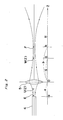
- Fig. 1 is a cross sectional view showing an embodiment of an optical code reading device according to the present invention,
- Fig. 2 is a schematic diagram showing a manner of throttling the light beam,
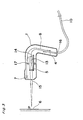
- Fig. 3 is a cross sectional view showing another embodiment of the optical code reading device according to the present invention,
- Fig. 4 is a cross sectional view showing a further embodiment of the optical code reading device according to the present invention, and
- Figs. 5 and 6 are cross sectional views showing details of the arrangement of the optical fibers used in the embodiment shown in Fig. 4.
- A scanning head 1 comprises a housing 1a made of a generally an L character shape and is movable in one dimension or two dimensions in parallel with a surface of an
object 6 to be read. - There are provided a moving
unit 100 for moving the scanning head 1 and amotion detecting unit 101 for detecting amount of movement of the scanning head 1 so as to make it possible to identify the read position and the information which is obtained at the read position. - A
floor type unit 2 secured on a suitable floor or the like is provided with a light source and data processing circuit. It is noted that conventionally the light source is provided in the scanning head, but in the preferred embodiment of the present invention, the light source is provided in thefloor type unit 2. - As the
light source 3, a semiconductor laser is used. The light emitted from thelight source 3 is throttled by alens 11. The light thus throttled is applied to anentrance unit 12 of a single modeoptical fiber 4. The single mode optical fiber means such an optical fiber that allows to pass only the 0 dimensional mode light of the incident light with the wave length A. The diameter of the core is extremely small. Therefore, it is necessary to use thecoupling lens 11 so that the light of the light source can be entered in the optical fiber core as many as possible. To use the coupling lens is a known technology. - The semiconductor laser is small in size and the life is long enough, and is suitable as the light source.
- However, as the light source, any other types such as He-Ne laser, Ar laser may be used except that the color of light is limited. He-Ne laser may be suitable since He- Ne laser has a good directionality and is inexpensive and the light therefrom is visible.
- In case green light is required, Ar laser may be used as the light source.
- A
calculation unit 9 is provided in thefloor type unit 2. - The signal mode
optical fiber 4 for transferring the light from the light source and acommunication cable 8 connected to thecalculation unit 9 are covered by acommon sheath 10. Both ends of theoptical fiber 4 andcommunication cable 8 are connected to aterminal 16 of the scanning head 1. - In the scanning head 1, there are provided an end portion of the single mode
optical fiber 4 and alens 5 for collecting the light from theoptical fiber 4. Thelight projecting end 13 of the single modeoptical fiber 4 is covered with a sleeve made of metal or the like and secured in the scanning head 1 by means of a securing member (not shown). The light collected by thelens 5 is projected outside through awindow 15 toward a point P of theobject 6 to be read. - A
photo diode 7 is provided inside thewindow 15 of the scanning head 1 for receiving light reflected from the point P, thereby to produce an electric signal representing the intensity of the reflected light. The electric signal of thephoto diode 7 is transferred to thecalculation unit 9 in thefloor type unit 2 through thecommunication cable 8. Thecalculation unit 9 processes the electric signals fed from thephoto diode 7 so as to produce electric signals representing the object code in a known manner. - According to the embodiment of the present invention, the light emitted from the light source 1 is entered in the single mode
optical fiber 4 and the light is closed in the optical fiber core of a small size. The light projected from the end of the single modeoptical fiber 4 is throttled by thelens 5, whereby the light beam can be throttled into a small diameter. - Since the light is projected from the optical fiber core having a true circle shape in its cross section, the shape of the light spot of the light beam projected from the single mode
optical fiber 4 is also a true circle shape, and the spot size of the light beam can be reduced by thelens 5. The single modeoptical fiber 4 is used so as to collect the light into a small area and to obtain the projected light beam pattern of a true circle shape. - Since the light source is not provided in the scanning head 1 but is provided in the
floor type unit 2, the size and weight of the scanning head 1 can be reduced up to such a size that the scanning head is placed on a human palm. - Due to the diffraction of light, light beam has a finite spot size. When the light is throttled by means of a lens system, the spot size of the light at respective points further than the point at which the minimum spot size is obtained is expanded.
- A condition for obtaining the minimum spot size is explained with reference to Fig. 2.
- It is assumed that the center of the
lens 5 is the origin O and the light projecting end of the single modeoptical fiber 4 is positioned after thelens 5 with a distance a. Assuming further that the radius of the spot size of the light at the projecting end of the single modeoptical fiber 4 is defined by E and the radius of the core of the single modeoptical fiber 4 is r₀ and the normalized frequency of the single modeoptical fiber 4 is V, the following equation is obtained.
rc = (0.65 + 1.619/V2/3 + 2.879/V⁶ ) E - Z axis is defined in the direction of the light progression. The end of the single mode
optical fiber 4 is Z = -a. Assuming that the light beam is a gaussian beam, the radius of the spot size of the light beam between the end (Z = -a) of the optical fiber and the lens(Z = 0) can be expressed as
U(Z)² = E² [1 + { λ(a + Z)/ πE²}²] (1) - In the equation (1) λ is the wave length of light.
- The radius of the light beam increases proportional to the square of the distance from the end of the single mode
optical fiber 4. - When the light has passed the
lens 5, the light is throttled and the spot size is reduced. Assuming that the spot size is minimum at a position Z = b, the position is referred to as a standard position. According to the assumption that the light beam is gaussian beam, the spot size of the light beam after the light passed thelens 5 is expressed as
W(Z)²= F²[1 = { λ(Z-b)/ πF²}²] (2). - It is best that the object to be read is positioned at the standard point Z = b, however, it is difficult to position the object at the standard point always. Therefore, there is defined an allowable range G to H with the center thereof taken at Z = b so that reading of the object can be performed so far as the object exists within the allowable range. The points G and H are referred to as the critical points.
- The point G near the
lens 5 is called a near critical point. The point H far from thelens 5 is called a far critical point. - The respective beam sizes W(G) and W(H) at the critical points G and H are the same value which can be calculated by the equation (2) using Δ = G-b = H-b.
- The beam sizes W(G) and W(H) are the function of the minimum beam radius F which can be selected as desired.
- The value F for obtaining the minimum beam radius at the critical points G and H can be calculated by the following calculation by defining the value F as an independent variable.
- Since an arithmetic mean is greater than a geometrical mean,
W(G)² = W(H)² ≧ 2 λ Δ/ π (3)
is obtained. In the above equation, equality is established when Fm =λ Δ/ π (4).
- The distance b up to the object and width Δ up to the critical point are given preliminarily. By the equation (4), the optimum minimum beam size Fm can be obtained.
- The beam radius at the critical point is
W(G) = W(H) = √2 Fm (5). - Since the values of the equations (1) and (2) when Z = 0 are equal,

- Under such a condition that the beam size is made minimum at the critical points G and H, by placing the value Fm for F, the value a can be obtained by the equation

lens 5 can be calculated

- An example of the device according to the present invention was provided using a single mode optical fiber of which radius E is 2.4 µm. The standard point b was 250 mm, near critical point G was 200 mm, the wave length λ of the light was 0.75 µm and Δwas 50mm.
- From the equation (4), the beam radius Fm was 109 µm and the beam radius W(G) of the near critical point was 154 µm. The value a was 5.58 mm and the focal length of the lens was 5.46 mm according to the value b was 250 mm.
- Therefore, when the light source of which wave length 0.75 µm is used and the light is applied to the single mode optical fiber of 2.4 µm radius of the spot size, by placing the
lens 5 at the position apart from the end of the single modeoptical fiber 4 with the distance 5.58 mm, the spot size of the light at the near critical point is 154 µm radius can be obtained. - According to the present embodiment, the light to be projected to the object is passed the single mode
optical fiber 4 and in turn thelens 5, so that the light beam can be throttled and the beam size is reduced enough keeping the spot shape in a true circle even if the point at which the light beam is projected is departed away from thewindow 15 of the scanning head 1, whereby a high reading resolution of the object can be obtained. - Moreover, since the light source and control unit including the
calculation unit 9 are accommodated in thefloor unit 2, it is possible to reduce the size of the scanning head 1. Therefore, the scanning head shown in the present embodiment is suitable for hand scanner for code reading device. - Referring to Fig. 3 showing another preferred embodiment of the present invention, wherein the
light projecting end 13 and thelens 5 are mounted on arotation mechanism 14 which is reciprocally rotatable around arotation axis 17 in one plane (in a horizontal plane) by a predetermined angle range so that the the
light projecting end 13 andlens 5 also can rotate and the light beam projected from thelens 5 can be moved along a scanning direction which is perpendicular to the axis of thelens 5. Therotation mechanism 14 is driven to rotate as mentioned above by a driving mechanism (not shown) which is provided in the housing of the scanning head 1. The power source for an electric motor (not shown) of the driving mechanism may be accommodated in thefloor unit 2 and the power for the electric motor is transferred to the scanning unit 1 by means of a suitable cable (not shown) Such cable may be covered with theoptical fibers sheath 10. - By rotating the
rotation mechanism 14 reciprocally in a predetermined angle range, the direction of the light projected from thelens 5 is changed along the scanning direction and theobject 6 can be scanned in a direction perpendicular to the lens axis, so that the detection point P can be changed time to time, whereby the light reflected from the code or character on theobject 6 can be consecutively detected by thephoto diode 7. - Since the rotation mechanism mounts only light weight elements such as the
lens 5 and thelight projecting end 13 of the single modeoptical fiber 4, it is possible to make the rotation mechanism simple. - Moreover, since the reflection mirror is not provided in the scanning head, the problem of stain of the mirror can be eliminated and the scanning head can be used under a bad atmosphere.
- Referring to Fig. 4 showing a further embodiment of the present invention, there is provided in the
floor unit 2 an LED 17 (light emitting diode) as an additional light source for emitting visible light. The light emitted from theLED 17 is used to sight the light beam of thelaser 3 on the object and therefore the light of theLED 17 is referred to as a sighting light hereinafter. The spot size of the sighting light is not necessarily to be fine, and various colors of LEDs are available in the market, therefore, LED is used as the source of the sighting light. In place of LED, an incadscent lamp may be used as the sighting light source. - The light from the
light source 3 is pulse modulated, while the light from theLED 17 is a D.C. light. - There are further provided in the floor unit 2 a
collimating lens 18 in front of theLED 17 to collimate the light from theLED 17 and a plural number ofoptical fibers  16 of a multi mode type each provided with a
light input end 22 in the form of a cylindrical sleeve made of metal. In the example shown, four optical fibers are used and the cross sectional view thereof is shown in Fig. 5. - There may be used a single optical fiber for transferring the light of LED. However, preferably a plurality of optical fibers may be used so that a large amount of light can be transferred to the scanning head as many as possible.
- There may be used one or more optical fibers of the single mode type. However, preferably the multi mode type optical fiber is used so that a large amount of light can be transferred to the scanning head as many as possible.
- The light of the
LED 17 is collimated by the collimatinglens 18 and the collimated light is applied to the light input ends 22 of the four multi mode optical fibers 116. - The four multi mode
optical fibers 16 and the single modeoptical fiber 4 as well as thecommunication cable 8 are covered by thesheath 10 and coupled to the scanning head 1 through anend terminal 26. The multi modeoptical fibers 16 are ended at output ends 23 made of sleeve and arranged in a manner as shown in Fig. 6. As shown in Fig. 6, the multi mode
optical fibers 16 and the sleeves or output ends 23 are disposed around the peripheral portions of the
sleeve 13 of the single modeoptical fiber 4. The number of the output ends 23 is equal to the number of the multi modeoptical fibers 16. The beams of the sighting light Π projected from the output ends or
sleeves 23 are throttled by alens 5 as well as the light Σ of reading the object from the single modeoptical fiber 4. Both of light beams Π and Σ are projected on theobject 6 through thewindow 15. - Since the output ends 13 and 23 are arranged similar to a coaxial manner, the light axis of the sighting light Π and that of the light Σ for reading the object coincide without light axis adjustment.
- The reading light Σ is projected on the
object 6 with a small spot size and the sighting light Π is projected on theobject 6 with relatively large spot size surrounding the spot of the reading light so as to facilitate to see the scanning point P at which the reading light Σ is projected. - The light reflected from the scanning point P is received by the
photo diode 7 and the intensity of the reflected light corresponds to the brightness and darkness of the scanning point or code to be read whereby the degree of the brightness and darkness of the scanning point P can be detected by the output of thephoto diode 7. The output of thephoto diode 7 is fed to thecalculation unit 9 in thefloor type unit 2 through thecommunication cable 8. - Since the reflected light contains reading light Σ and sighting light Π. However, since the reading light Σ is pulse modulated, by taking the pulse modulated component in the output of the
photo diode 17 by thecalculation unit 9, the component of the sighting light Σ can be detected and the code or character of the object can be read. - Since the detecting point P to which the reading light is projected is illuminated by the sighting light Σ, the detecting point can be easily seen, whereby scanning operation of the scanning head is easy.
- In the arrangement mentioned above, since the reading light Σ and sighting light Π can be combined only by the optical fibers and lens and there is no need to provide such as half mirror used in the prior art, the scanning head can be made small in size and light in weight and the structure of the scanning head becomes simple. Moreover, adjustment of light axes of the reading light Σ and the sighting light Π is unnecessary, the scanning head can manufactured easily.
Claims (9)
Applications Claiming Priority (6)
| Application Number | Priority Date | Filing Date | Title |
|---|---|---|---|
| JP61254232A JPS63106883A (en) | 1986-10-24 | 1986-10-24 | Optical system for code reader |
| JP254232/86 | 1986-10-24 | ||
| JP62153980A JPS63317888A (en) | 1987-06-19 | 1987-06-19 | Illumination optical system for code reader |
| JP153980/87 | 1987-06-19 | ||
| JP164764/87 | 1987-06-30 | ||
| JP62164764A JPS648491A (en) | 1987-06-30 | 1987-06-30 | Illuminating optical system for code reader |
Related Child Applications (1)
| Application Number | Title | Priority Date | Filing Date |
|---|---|---|---|
| EP91119175.7 Division-Into | 1991-11-11 |
Publications (3)
| Publication Number | Publication Date |
|---|---|
| EP0264956A2 true EP0264956A2 (en) | 1988-04-27 |
| EP0264956A3 EP0264956A3 (en) | 1989-02-15 |
| EP0264956B1 EP0264956B1 (en) | 1992-12-30 |
Family
ID=27320575
Family Applications (2)
| Application Number | Title | Priority Date | Filing Date |
|---|---|---|---|
| EP87115598A Expired - Lifetime EP0264956B1 (en) | 1986-10-24 | 1987-10-23 | An optical code reading device |
| EP91119175A Expired - Lifetime EP0478000B1 (en) | 1986-10-24 | 1987-10-23 | An optical code reading device |
Family Applications After (1)
| Application Number | Title | Priority Date | Filing Date |
|---|---|---|---|
| EP91119175A Expired - Lifetime EP0478000B1 (en) | 1986-10-24 | 1987-10-23 | An optical code reading device |
Country Status (4)
| Country | Link |
|---|---|
| US (1) | US4847490A (en) |
| EP (2) | EP0264956B1 (en) |
| CA (1) | CA1294045C (en) |
| DE (2) | DE3783315T2 (en) |
Cited By (15)
| Publication number | Priority date | Publication date | Assignee | Title |
|---|---|---|---|---|
| EP0341717A2 (en) * | 1988-05-11 | 1989-11-15 | Symbol Technologies, Inc. | Mirrorless scanners with movable lase, optical and sensor components |
| US5254844A (en) * | 1988-05-11 | 1993-10-19 | Symbol Technologies, Inc. | Mirrorless scanners with movable laser, optical and sensor components |
| US5404001A (en) * | 1992-10-08 | 1995-04-04 | Bard; Simon | Fiber optic barcode reader |
| US5416310A (en) * | 1993-05-28 | 1995-05-16 | Symbol Technologies, Inc. | Computer and/or scanner system incorporated into a garment |
| US5422469A (en) * | 1989-10-30 | 1995-06-06 | Symbol Technologies, Inc. | Fiber optic barcode readers using purely mechanical scanner oscillation |
| US5491651A (en) * | 1992-05-15 | 1996-02-13 | Key, Idea Development | Flexible wearable computer |
| US5514861A (en) * | 1988-05-11 | 1996-05-07 | Symbol Technologies, Inc. | Computer and/or scanner system mounted on a glove |
| US5555490A (en) * | 1993-12-13 | 1996-09-10 | Key Idea Development, L.L.C. | Wearable personal computer system |
| US5572401A (en) * | 1993-12-13 | 1996-11-05 | Key Idea Development L.L.C. | Wearable personal computer system having flexible battery forming casing of the system |
| US5610387A (en) * | 1992-05-15 | 1997-03-11 | Symbol Technologies, Inc. | Portable optical scanning system worn by a user for reading indicia of differing light reflectivity |
| US6097607A (en) * | 1996-11-01 | 2000-08-01 | Via, Inc. | Flexible computer system |
| US6637660B2 (en) * | 1997-10-16 | 2003-10-28 | Tohoku Ricoh Co., Ltd. | Bar code reader |
| US6811088B2 (en) | 1993-05-28 | 2004-11-02 | Symbol Technologies, Inc. | Portable data collection system |
| US6853293B2 (en) | 1993-05-28 | 2005-02-08 | Symbol Technologies, Inc. | Wearable communication system |
| EP1906294A2 (en) | 1999-05-03 | 2008-04-02 | Symbol Technologies, Inc. | Wearable communication system |
Families Citing this family (21)
| Publication number | Priority date | Publication date | Assignee | Title |
|---|---|---|---|---|
| US5340971A (en) * | 1990-09-17 | 1994-08-23 | Metrologic Instruments, Inc. | Automatic bar code reading system having selectable long range and short range modes of operation |
| IL98337A (en) * | 1991-06-02 | 1995-01-24 | Pinchas Schechner | Production control by multiple branch bar-code readers |
| US5237162A (en) * | 1991-06-10 | 1993-08-17 | Spectra-Physics Scanning Systems, Inc. | Handheld laser scanner with contoured hand rest |
| JP2899113B2 (en) * | 1994-10-25 | 1999-06-02 | ユナイテッド パーセル サービス オブ アメリカ,インコーポレイテッド | Method and apparatus for portable non-contact label imager |
| US20030019934A1 (en) * | 1998-07-08 | 2003-01-30 | Hand Held Products, Inc. | Optical reader aiming assembly comprising aperture |
| US6601768B2 (en) | 2001-03-08 | 2003-08-05 | Welch Allyn Data Collection, Inc. | Imaging module for optical reader comprising refractive diffuser |
| US6075240A (en) * | 1998-07-30 | 2000-06-13 | Nec Usa, Inc. | Hand-held plastic optical fiber linear scanner for reading color images formed on a surface |
| US6157027A (en) * | 1998-12-01 | 2000-12-05 | Nec Usa, Inc. | Modular optical fiber color image scanner with all-optical scanner head having side-coupled light guide for providing illumination light to the scanner head |
| US6445139B1 (en) * | 1998-12-18 | 2002-09-03 | Koninklijke Philips Electronics N.V. | Led luminaire with electrically adjusted color balance |
| CN1391680A (en) * | 1999-10-04 | 2003-01-15 | 韦尔奇·埃林数据采集公司 | Imaging module for optical reader |
| US6832725B2 (en) | 1999-10-04 | 2004-12-21 | Hand Held Products, Inc. | Optical reader comprising multiple color illumination |
| US7270274B2 (en) | 1999-10-04 | 2007-09-18 | Hand Held Products, Inc. | Imaging module comprising support post for optical reader |
| US7464877B2 (en) * | 2003-11-13 | 2008-12-16 | Metrologic Instruments, Inc. | Digital imaging-based bar code symbol reading system employing image cropping pattern generator and automatic cropped image processor |
| US7055747B2 (en) * | 2002-06-11 | 2006-06-06 | Hand Held Products, Inc. | Long range optical reader |
| US20030222147A1 (en) | 2002-06-04 | 2003-12-04 | Hand Held Products, Inc. | Optical reader having a plurality of imaging modules |
| US7219843B2 (en) * | 2002-06-04 | 2007-05-22 | Hand Held Products, Inc. | Optical reader having a plurality of imaging modules |
| US7090132B2 (en) * | 2002-06-11 | 2006-08-15 | Hand Held Products, Inc. | Long range optical reader |
| US8596542B2 (en) | 2002-06-04 | 2013-12-03 | Hand Held Products, Inc. | Apparatus operative for capture of image data |
| US8561903B2 (en) | 2011-01-31 | 2013-10-22 | Hand Held Products, Inc. | System operative to adaptively select an image sensor for decodable indicia reading |
| US8608071B2 (en) | 2011-10-17 | 2013-12-17 | Honeywell Scanning And Mobility | Optical indicia reading terminal with two image sensors |
| CN113764116B (en) * | 2021-09-27 | 2023-11-21 | 桂林电子科技大学 | Single-fiber optical tweezers based on optical sharp edge diffraction |
Citations (3)
| Publication number | Priority date | Publication date | Assignee | Title |
|---|---|---|---|---|
| US3809893A (en) * | 1971-01-08 | 1974-05-07 | Monarch Marking Systems Inc | Optical reader |
| EP0137966A2 (en) * | 1983-08-22 | 1985-04-24 | Optel Systems, Inc. | Optical device for detecting coded symbols |
| US4560862A (en) * | 1983-04-26 | 1985-12-24 | Skan-A-Matic Corp. | System for optical scanning over a large depth of field |
Family Cites Families (12)
| Publication number | Priority date | Publication date | Assignee | Title |
|---|---|---|---|---|
| US3449587A (en) * | 1965-02-11 | 1969-06-10 | Kollsman Instr Corp | Fibre optic scanner device for navigational instruments |
| US3475612A (en) * | 1967-07-03 | 1969-10-28 | Information Control Corp | Light pen casing and circuit in which the output signal is enabled when two spaced surface portions are both engaged by the operator's hand |
| US3584779A (en) * | 1968-10-07 | 1971-06-15 | Ncr Co | Optical data sensing system |
| GB1375963A (en) * | 1970-12-17 | 1974-12-04 | Plessey Co Ltd | Data handling systems |
| US3711723A (en) * | 1972-02-04 | 1973-01-16 | Ibm | Optical system for optical fiber bundle scanning apparatus |
| JPS56820B2 (en) * | 1972-12-13 | 1981-01-09 | ||
| US3916184A (en) * | 1974-01-16 | 1975-10-28 | Welch Allyn Inc | Optical scanner in modular form |
| US3983389A (en) * | 1975-04-11 | 1976-09-28 | International Business Machines Corporation | Wand for reading optically encoded graphic symbols |
| US4286145A (en) * | 1980-02-20 | 1981-08-25 | General Dynamics, Pomona Division | Fiber optic bar code reader |
| US4673805A (en) * | 1982-01-25 | 1987-06-16 | Symbol Technologies, Inc. | Narrow-bodied, single- and twin-windowed portable scanning head for reading bar code symbols |
| NL8303168A (en) * | 1983-09-14 | 1985-04-01 | Philips Nv | DEVICE FOR READING BARS CODED INFORMATION. |
| DE3477271D1 (en) * | 1984-12-28 | 1989-04-20 | Ibm | Waveguide for an optical near-field microscope |
-
1987
- 1987-10-23 EP EP87115598A patent/EP0264956B1/en not_active Expired - Lifetime
- 1987-10-23 US US07/111,639 patent/US4847490A/en not_active Expired - Fee Related
- 1987-10-23 EP EP91119175A patent/EP0478000B1/en not_active Expired - Lifetime
- 1987-10-23 DE DE8787115598T patent/DE3783315T2/en not_active Expired - Fee Related
- 1987-10-23 CA CA000550096A patent/CA1294045C/en not_active Expired - Fee Related
- 1987-10-23 DE DE3788734T patent/DE3788734T2/en not_active Expired - Fee Related
Patent Citations (3)
| Publication number | Priority date | Publication date | Assignee | Title |
|---|---|---|---|---|
| US3809893A (en) * | 1971-01-08 | 1974-05-07 | Monarch Marking Systems Inc | Optical reader |
| US4560862A (en) * | 1983-04-26 | 1985-12-24 | Skan-A-Matic Corp. | System for optical scanning over a large depth of field |
| EP0137966A2 (en) * | 1983-08-22 | 1985-04-24 | Optel Systems, Inc. | Optical device for detecting coded symbols |
Cited By (22)
| Publication number | Priority date | Publication date | Assignee | Title |
|---|---|---|---|---|
| EP0742530A2 (en) * | 1988-05-11 | 1996-11-13 | Symbol Technologies, Inc. | Mirrorless scanners with movable laser, optical and sensor components |
| US5254844A (en) * | 1988-05-11 | 1993-10-19 | Symbol Technologies, Inc. | Mirrorless scanners with movable laser, optical and sensor components |
| EP0742530B1 (en) * | 1988-05-11 | 2004-07-14 | Symbol Technologies, Inc. | Mirrorless scanners with movable laser, optical and sensor components |
| EP0341717B1 (en) * | 1988-05-11 | 1997-07-23 | Symbol Technologies, Inc. | Mirrorless scanner with movable laser and optical components |
| EP0341717A2 (en) * | 1988-05-11 | 1989-11-15 | Symbol Technologies, Inc. | Mirrorless scanners with movable lase, optical and sensor components |
| US5514861A (en) * | 1988-05-11 | 1996-05-07 | Symbol Technologies, Inc. | Computer and/or scanner system mounted on a glove |
| US5422469A (en) * | 1989-10-30 | 1995-06-06 | Symbol Technologies, Inc. | Fiber optic barcode readers using purely mechanical scanner oscillation |
| US5491651A (en) * | 1992-05-15 | 1996-02-13 | Key, Idea Development | Flexible wearable computer |
| US5798907A (en) * | 1992-05-15 | 1998-08-25 | Via, Inc. | Wearable computing device with module protrusion passing into flexible circuitry |
| US6108197A (en) * | 1992-05-15 | 2000-08-22 | Via, Inc. | Flexible wearable computer |
| US5610387A (en) * | 1992-05-15 | 1997-03-11 | Symbol Technologies, Inc. | Portable optical scanning system worn by a user for reading indicia of differing light reflectivity |
| US5581492A (en) * | 1992-05-15 | 1996-12-03 | Key Idea Development, L.L.C. | Flexible wearable computer |
| US5521367A (en) * | 1992-10-08 | 1996-05-28 | Symbol Technologies, Inc. | Fiber optic barcode reader with piezoelectric element |
| US5404001A (en) * | 1992-10-08 | 1995-04-04 | Bard; Simon | Fiber optic barcode reader |
| US5416310A (en) * | 1993-05-28 | 1995-05-16 | Symbol Technologies, Inc. | Computer and/or scanner system incorporated into a garment |
| US6811088B2 (en) | 1993-05-28 | 2004-11-02 | Symbol Technologies, Inc. | Portable data collection system |
| US6853293B2 (en) | 1993-05-28 | 2005-02-08 | Symbol Technologies, Inc. | Wearable communication system |
| US5555490A (en) * | 1993-12-13 | 1996-09-10 | Key Idea Development, L.L.C. | Wearable personal computer system |
| US5572401A (en) * | 1993-12-13 | 1996-11-05 | Key Idea Development L.L.C. | Wearable personal computer system having flexible battery forming casing of the system |
| US6097607A (en) * | 1996-11-01 | 2000-08-01 | Via, Inc. | Flexible computer system |
| US6637660B2 (en) * | 1997-10-16 | 2003-10-28 | Tohoku Ricoh Co., Ltd. | Bar code reader |
| EP1906294A2 (en) | 1999-05-03 | 2008-04-02 | Symbol Technologies, Inc. | Wearable communication system |
Also Published As
| Publication number | Publication date |
|---|---|
| EP0478000B1 (en) | 1994-01-05 |
| DE3788734T2 (en) | 1994-06-23 |
| DE3783315D1 (en) | 1993-02-11 |
| EP0264956B1 (en) | 1992-12-30 |
| CA1294045C (en) | 1992-01-07 |
| DE3788734D1 (en) | 1994-02-17 |
| US4847490A (en) | 1989-07-11 |
| EP0264956A3 (en) | 1989-02-15 |
| DE3783315T2 (en) | 1993-05-13 |
| EP0478000A1 (en) | 1992-04-01 |
Similar Documents
| Publication | Publication Date | Title |
|---|---|---|
| US4847490A (en) | Optical code reading device whose laser reading light is transmitted by only one single mode optical fiber | |
| EP1281271B1 (en) | Coplanar camera scanning system | |
| US5406060A (en) | Bar code reader for sensing at an acute angle | |
| US6330974B1 (en) | High resolution laser imager for low contrast symbology | |
| US4558357A (en) | Color image reading method and apparatus | |
| US5912451A (en) | Moving beam and field of view readers with dichroic filter | |
| CA2198283C (en) | Three dimensional color imaging | |
| US4753498A (en) | Optical reader | |
| EP0101939A2 (en) | Apparatus for optically reading information | |
| EP0183240A2 (en) | Surface position sensor | |
| EP0752680A1 (en) | Optical scanners having dual surface optical elements for dual working ranges | |
| US5308964A (en) | Variable resolution wand | |
| EP3413078A1 (en) | Object detection device of optical scanning type | |
| EP0882211B1 (en) | A method and apparatus for reducing the unwanted effects of noise present in a three-dimensional color imaging system | |
| CN1591468B (en) | Method and device for optical navigation | |
| US6208465B1 (en) | Method and apparatus for imaging an object by diffractive autofocus | |
| EP0553698A1 (en) | Optical scanning device | |
| US5650869A (en) | Point relay scanner utilizing ellipsoidal mirrors | |
| US4966429A (en) | Optical scale reading apparatus | |
| CN216115894U (en) | Multi-wavelength hand-held three-dimensional laser scanner | |
| US20030151788A1 (en) | Optoelectronic device | |
| RU2156434C2 (en) | Opticoelectronic converter for contact-free measurement of linear displacement and ( or ) diameter | |
| JPH0572033A (en) | Optical spectrum analyzer | |
| JPS62256094A (en) | Bar code reader | |
| JPH10160624A (en) | Device for detection hidden mark of spectacle lens |
Legal Events
| Date | Code | Title | Description |
|---|---|---|---|
| PUAI | Public reference made under article 153(3) epc to a published international application that has entered the european phase |
Free format text: ORIGINAL CODE: 0009012 |
|
| AK | Designated contracting states |
Kind code of ref document: A2 Designated state(s): DE FR GB IT |
|
| PUAL | Search report despatched |
Free format text: ORIGINAL CODE: 0009013 |
|
| AK | Designated contracting states |
Kind code of ref document: A3 Designated state(s): DE FR GB IT |
|
| 17P | Request for examination filed |
Effective date: 19890320 |
|
| 17Q | First examination report despatched |
Effective date: 19901218 |
|
| GRAA | (expected) grant |
Free format text: ORIGINAL CODE: 0009210 |
|
| AK | Designated contracting states |
Kind code of ref document: B1 Designated state(s): DE FR GB IT |
|
| XX | Miscellaneous (additional remarks) |
Free format text: TEILANMELDUNG 91119175.7 EINGEREICHT AM 23/10/87. |
|
| ITF | It: translation for a ep patent filed |
Owner name: JACOBACCI CASETTA & PERANI S.P.A. |
|
| REF | Corresponds to: |
Ref document number: 3783315 Country of ref document: DE Date of ref document: 19930211 |
|
| ET | Fr: translation filed | ||
| REG | Reference to a national code |
Ref country code: GB Ref legal event code: 746 Effective date: 19930715 |
|
| ITPR | It: changes in ownership of a european patent |
Owner name: OFFERTA DI LICENZA AL PUBBLICO |
|
| PLBE | No opposition filed within time limit |
Free format text: ORIGINAL CODE: 0009261 |
|
| STAA | Information on the status of an ep patent application or granted ep patent |
Free format text: STATUS: NO OPPOSITION FILED WITHIN TIME LIMIT |
|
| REG | Reference to a national code |
Ref country code: FR Ref legal event code: DL |
|
| 26N | No opposition filed | ||
| PGFP | Annual fee paid to national office [announced via postgrant information from national office to epo] |
Ref country code: FR Payment date: 19951010 Year of fee payment: 9 |
|
| PGFP | Annual fee paid to national office [announced via postgrant information from national office to epo] |
Ref country code: GB Payment date: 19951016 Year of fee payment: 9 |
|
| PGFP | Annual fee paid to national office [announced via postgrant information from national office to epo] |
Ref country code: DE Payment date: 19951026 Year of fee payment: 9 |
|
| PG25 | Lapsed in a contracting state [announced via postgrant information from national office to epo] |
Ref country code: GB Effective date: 19961023 |
|
| GBPC | Gb: european patent ceased through non-payment of renewal fee |
Effective date: 19961023 |
|
| PG25 | Lapsed in a contracting state [announced via postgrant information from national office to epo] |
Ref country code: FR Effective date: 19970630 |
|
| PG25 | Lapsed in a contracting state [announced via postgrant information from national office to epo] |
Ref country code: DE Effective date: 19970701 |
|
| REG | Reference to a national code |
Ref country code: FR Ref legal event code: ST |
|
| PG25 | Lapsed in a contracting state [announced via postgrant information from national office to epo] |
Ref country code: IT Free format text: LAPSE BECAUSE OF NON-PAYMENT OF DUE FEES;WARNING: LAPSES OF ITALIAN PATENTS WITH EFFECTIVE DATE BEFORE 2007 MAY HAVE OCCURRED AT ANY TIME BEFORE 2007. THE CORRECT EFFECTIVE DATE MAY BE DIFFERENT FROM THE ONE RECORDED. Effective date: 20051023 |