EP0266493A1 - Removal of mercury from natural gas - Google Patents
Removal of mercury from natural gas Download PDFInfo
- Publication number
- EP0266493A1 EP0266493A1 EP87111420A EP87111420A EP0266493A1 EP 0266493 A1 EP0266493 A1 EP 0266493A1 EP 87111420 A EP87111420 A EP 87111420A EP 87111420 A EP87111420 A EP 87111420A EP 0266493 A1 EP0266493 A1 EP 0266493A1
- Authority
- EP
- European Patent Office
- Prior art keywords
- mercury
- liquid
- gas
- hydrocarbon liquid
- separated
- Prior art date
- Legal status (The legal status is an assumption and is not a legal conclusion. Google has not performed a legal analysis and makes no representation as to the accuracy of the status listed.)
- Granted
Links
Images

Classifications
-
- B—PERFORMING OPERATIONS; TRANSPORTING
- B01—PHYSICAL OR CHEMICAL PROCESSES OR APPARATUS IN GENERAL
- B01D—SEPARATION
- B01D53/00—Separation of gases or vapours; Recovering vapours of volatile solvents from gases; Chemical or biological purification of waste gases, e.g. engine exhaust gases, smoke, fumes, flue gases, aerosols
- B01D53/14—Separation of gases or vapours; Recovering vapours of volatile solvents from gases; Chemical or biological purification of waste gases, e.g. engine exhaust gases, smoke, fumes, flue gases, aerosols by absorption
- B01D53/1493—Selection of liquid materials for use as absorbents
-
- B—PERFORMING OPERATIONS; TRANSPORTING
- B01—PHYSICAL OR CHEMICAL PROCESSES OR APPARATUS IN GENERAL
- B01D—SEPARATION
- B01D19/00—Degasification of liquids
-
- B—PERFORMING OPERATIONS; TRANSPORTING
- B01—PHYSICAL OR CHEMICAL PROCESSES OR APPARATUS IN GENERAL
- B01D—SEPARATION
- B01D19/00—Degasification of liquids
- B01D19/0068—General arrangements, e.g. flowsheets
-
- B—PERFORMING OPERATIONS; TRANSPORTING
- B01—PHYSICAL OR CHEMICAL PROCESSES OR APPARATUS IN GENERAL
- B01D—SEPARATION
- B01D53/00—Separation of gases or vapours; Recovering vapours of volatile solvents from gases; Chemical or biological purification of waste gases, e.g. engine exhaust gases, smoke, fumes, flue gases, aerosols
- B01D53/14—Separation of gases or vapours; Recovering vapours of volatile solvents from gases; Chemical or biological purification of waste gases, e.g. engine exhaust gases, smoke, fumes, flue gases, aerosols by absorption
- B01D53/1418—Recovery of products
-
- Y—GENERAL TAGGING OF NEW TECHNOLOGICAL DEVELOPMENTS; GENERAL TAGGING OF CROSS-SECTIONAL TECHNOLOGIES SPANNING OVER SEVERAL SECTIONS OF THE IPC; TECHNICAL SUBJECTS COVERED BY FORMER USPC CROSS-REFERENCE ART COLLECTIONS [XRACs] AND DIGESTS
- Y10—TECHNICAL SUBJECTS COVERED BY FORMER USPC
- Y10S—TECHNICAL SUBJECTS COVERED BY FORMER USPC CROSS-REFERENCE ART COLLECTIONS [XRACs] AND DIGESTS
- Y10S62/00—Refrigeration
- Y10S62/917—Mercury
Definitions
- This invention relates to a process for removal of mercury from gases. More particularly the invention relates to removal of mercury from natural gas.
- Mercury has been found in natural gas fields throughout the world in concentrations ranging from a trace to as much as 1000 ⁇ g/Nm3. While moderate to high concentrations of mercury can present specific industrial health problems and may poison certain catalysts used in natural gas-feed processes, it has been learned in recent years that even very low amounts of mercury in gas-feed cryogenic process plants cause corrosion in aluminum alloy equipment as the mercury accumulates in various items of equipment. Mercury-induced corrosion, particularly in the presence of water, has been known for some time but the specific corrosion mechanisms are not fully understood. Mercury removal from feed gas is, therefore, the only currently available remedy for the problem.
- the most commonly used technique for mercury removal from natural gas at the present time employs gas treatment with sulfur impregnated activated carbon sorbent or proprietary sorbents. These dry, particulate sorbents are usually employed in the upstream gas treating sections of a cryogenic process plant and, when fresh, can remove mercury to a typical level of 0.1 ⁇ g/Nm3. Sorbents must be replaced when mercury content of treated gas rises. While sorbent treatment is reasonably satisfactory in commercial practice, lower mercury content in the treated gas would significantly reduce the prospects of mercury-induced corrosion in cryogenic equipment. Other mercury removal techniques such as formation of various amalgams are known but are not useful where very low mercury contents are required.
- natural gas containing mercury is contacted with a mercury-free hydrocarbon liquid having a molecular weight between 20 and 130 in a gas/liquid contacting zone from which a mercury-enriched hydrocarbon liquid is recovered and a mercury-lean methane-rich gas is recovered.
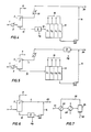
- Figure 1 is a flow scheme of an embodiment of the invention wherein a normally gaseous hydrocarbon is employed as the first mercury-free hydrocarbon liquid in the gas/liquid contacting zone, mercury is separated from the contacting zone liquid effluent, and a portion of LPG recovered from the resulting second mercury-free hydrocarbon liquid is recycled.
- a normally gaseous hydrocarbon is employed as the first mercury-free hydrocarbon liquid in the gas/liquid contacting zone, mercury is separated from the contacting zone liquid effluent, and a portion of LPG recovered from the resulting second mercury-free hydrocarbon liquid is recycled.
- Figure 2 is a flow scheme of another embodiment of the invention varying from Figure 1 in that mercury is separated from a portion of the LPG product streams to form a recycle stream.
- Figure 3 is a flow scheme of another embodiment of the invention varying from Figure 1 in that the first mercury-free hydrocarbon liquid is recovered entirely from vapor overhead of the gas/liquid contacting zone through an absorber recycle circuit including a mercury separation step.
- Figure 4 is a flow scheme of another embodiment of the invention wherein a normally liquid hydrocarbon is employed as the first mercury-free hydrocarbon liquid in the gas/liquid contacting zone, mercury is separated from the contacting zone liquid effluent, and a portion of mercury-free gasoline recovered from a downstream LPG unit is recycled.
- Figure 5 is a flow scheme of another embodiment of the invention varying from Figure 4 in that mercury is removed from the recycle gasoline stream.
- Figure 6 is a flow scheme of another embodiment of the invention varying from Figure 4 in that LPG is not separated, warmer temperatures are employed, and m ercury removal is not as complete as in previous flow schemes.
- Figure 7 is a flow scheme of another embodiment of the invention illustrating a preferred method of mercury separation by chilling the hydrocarbon stream.
- the first mercury-free hydrocarbon liquid used in the gas/liquid contacting zone may be principally a normally gaseous hydrocarbon or principally a normally liquid hydrocarbon.
- the phrase “mercury-free” is relative because of the low levels of mercury under consideration as well as the technical difficulty of measurement.
- mercury-free hydrocarbon liquid means a liquid phase hydrocarbon or hydrocarbon mixtures containing from 0- to 100 ppb (parts per billion by moles) mercury.
- mercury-free hydrocarbon liquids containing from 0 to 5 ppb mercury For cryogenic services we prefer to employ mercury-free hydrocarbon liquids containing from 0 to 5 ppb mercury.
- first mercury-free hydrocarbon liquid is normally gaseous as will typically be the instance in cryogenic process plants
- the gas/liquid contacting zone is typically operated at a temperature between 10°C and -85°C.
- the primary mercury absorber overhead is typically operated at a temperature between 0°C and -75°C.
- the mercury-lean methane-rich gas leaving the primary absorber is further cooled to between -30°C and -85°C to condense additional hydrocarbons heavier than methane from the gas stream.
- This condensation step which may be regarded as extension of the gas/liquid contacting zone, further reduces mercury content of the vapor phase mercury-lean methane-rich gas to be liquefied in downstream cryogenic equipment.
- the mercury-enriched hydrocarbon liquid recovered from the gas/liquid contactor is comprised principally of natural gas liquids (NGL) which may be burned as fuel, employed as feedstock for other processes, or, more usually, separated into component streams to recover C3/C4 mixtures for sale as LP gas.
- NGL natural gas liquids
- Mercury may be removed from liquid leaving the absorber by sorbents or other means but we prefer to chill the stream and settle out the mercury as a liquid or, most preferably, as a solid.
- a mercury separation unit of this type is simple, effective, and not very costly.
- the mercury separation unit treats the entire stream recovered from the primary absorber to form a second mercury-free liquid
- the LPG streams taken therefrom in a downstream separation unit will be essentially mercury-free.
- a normally gaseous recycle stream preferably a C3/C4 mixture
- mercury separation from the principal LP and light gasoline streams is not necessary, mercury may be separated from the normally gaseous recycle stream taken from the LPG unit and used as part or all of the first mercury-free hydrocarbon liquid.
- gas liquids comprising propane and butane may be condensed therefrom, treated in a mercury separation unit, and employed as part or all of the first mercury-free hydrocarbon liquid.
- the first mercury-free hydrocarbon liquid is normally liquid and gas/liquid contacting zone is operated at a temperature between 40°C and -40°C.
- the mercury-free hydrocarbon liquid will be between 40°C and -45°C; the choice within the range being principally determined by the type of mercury separation unit employed and component freezing points of the normally liquid hydrocarbon.
- the normal liquid will comprise principally gasoline, sometimes referred to as "lean oil", which is customarily separated from the wellhead gas.
- the resulting stream is cooled in exchanger 2 to -23°C and introduced to primary absorber 3 where contained mercury is absorbed into a first mercury-free liquid stream 4 comprised principally of ethane, propane, and butane which enters the absorber at a temperature of -37°C.
- Mercury-lean methane-rich gas leaves the absorber via line 5 and is combined with a mercury-free, normally gaseous recycle stream 6 comprised principally of propane and butane.
- the resulting mixed stream is cooled to -37°C in heat exchanger 7 and introduced to vapor/liquid separator 8 where condensed C2+ hydrocarbons from lines 5 and 6 are separated and pumped to the absorber through line 4 and as the first mercury-free liquid stream having the following composition: Methane 28.0 mole percent C2 21.0 mole percent C3 20.0 mole percent C4 30.0. mole percent C5+ 1.0 mole percent Mercury 1.4 ppb (molar)
- methane-rich stream 9 leaving separator 8 is substantially mercury-free and is introduced to downstream liquefaction facilities not shown. Obviously, not all of the methane-rich gas from the absorber need be liquefied and portions thereof may be taken for fuel use and/or pipeline transmission as gas.
- a mercury-enriched hydrocarbon liquid is recovered in line 10 and introduced to mercury separation unit 11 which preferably employs the process scheme of Figure 7.
- a second mercury-free hydrocarbon liquid is recovered from the mercury removal unit and introduced through line 12 to natural gas liquids (NGL) separation unit 13 from which light gasoline is recovered in line 14 and separated C1-C4 components are recovered through product lines collectively indicated as 15.
- a portion of one or more of the separated C2-C4 components is taken from the product lines through line 16 as normally gaseous recycle stream 16 and cooled to -29°C in exchanger 17 for introduction to the absorber overhead circuit as a liquid through line 6.
- the choice of components of the normally gaseous recycle stream is determined largely by economics of a particular facility and may be any of available C2-C5 components. In general, we prefer use of a propane and butane blend.
- FIG. 2 illustrates a variation of the process scheme of Figure 1 wherein mercury removal unit 11 treats the recycle stream 16 removed from the NGL f acility 13. This arrangement is satisfactory where mercury content in product lines 14 and 15 are acceptable. Line 18 is for optional downstream reinjection of C3/C4 components into the liquefied natural gas product.
- Figure 3 illustrates an embodiment of the invention in which the natural gas liquids content of the entering gas in line 1 is large enough to condense sufficient liquid from methane-rich gas in line 5 which is then treated in mercury removal unit 11 to separate mercury, preferably, in solid state and furnish the first mercury-free hydrocarbon liquid stream 4 to gas/liquid contactor 3.
- a recycle stream from the LPG unit is not employed. In this instance, sufficient C2+ components are available to provide the necessary liquid flow rates in absorber 3.
- heat exchanger 7 may, for example, be of falling film absorber design cooled by mixed refrigerant and, optionally, located on the downstream vapor side of separator 8. The heat exchanger and separator may, alternatively, be integrated into a single equipment item.
- separator 8 is operated at -37°C which will reduce mercury content of the methane-rich gas to a level of about 0.1 ⁇ g/Nm3.
- the column overhead circuit will be designed and operated in a manner that the separation zone corresponding to separator 8 will have a colder temperature between -50°C and -75°C in order to condense more liquids and thereby reduce mercury concentration in the methane-rich gas to between 0.01 and 0.001 ⁇ g/Nm3.
- Figure 4 illustrates an embodiment of the invention in which the methane-rich product in line 9 may not be liquefied but, nevertheless, a mercury-lean gas is desired.
- This embodiment also illustrates use of a normally liquid hydrocarbon as principal constituent of the first mercury-free hydrocarbon liquid in line 4.
- the entering gas is cooled to -34°C in exchanger 2 in order to enrich stream 10 with C4 and lighter components.
- a lean oil stream 14 having a molecular weight of 80 is recovered and chilled to -37°C in exchanger 19 for use as the first mercury-free hydrocarbon liquid.
- Excess liquid not needed in absorber 3 is recovered through line 20 as product or for other services.
- FIG. 5 illustrates a variation of the process scheme of Figure 4 wherein mercury removal unit 11 treats the recycle portion of stream 14 recovered from the LPG facility 13.
- Figure 6 also illustrates an embodiment of the invention using a normally liquid hydrocarbon as principal constituent of the first mercury-free hydrocarbon liquid in line 4 in the instance, for example, where mercury removal is desired for toxological ra ther than corrosion reasons.
- a typical instance is where a pipeline gas containing C2 and C3 components is desired and recovered through line 9 and separation of the absorber effluent liquid stream is not required.
- the overhead gas in line 9 does not have to be cooled to cryogenic temperatures and the gas/liquid contacting zone may be operated between 40°C and -40°C.
- FIG. 7 illustrates an embodiment of the invention with respect to mercury removal as a liquid or, preferably, as solids from mercury-contaminated liquid streams formed, for example, in the previously described embodiments.
- the mercury-contaminated hydrocarbon stream 21 is cooled to a temperature between -18°C and -155°C in exchangers 22 and 23 and introduced to separation zone 24 which may be a simple settling tank.
- Separated zone 24 which may be a simple settling tank.
- Substantially mercury-free liquid is continuously withdrawn from the upper portion of the separator through line 25 while liquid or solid mercury is withdrawn, usually intermittently, through line 26.
- the temperature to which the mercury-contaminated liquid stream is cooled will depend principally upon mercury removal requirements of the overall process, the specific choice of hydrocarbons for use in the first mercury-free hydrocarbon liquid stream and location of the mercury removal unit in the overall process. Since mercury solubility increases with rising temperature, it follows that a hydrocarbon liquid having a very low mercury content may be obtained by very low temperature operation of the mercury removal unit described above.
- the mercury separation step is employed on the liquid stream introduced to the primary absorber as shown for example in Figures 2 and 3, we prefer to separate mercury at a temperature between -45°C and -160°C.
- the separation is made at a temperature between -20°C and -100°C.
Abstract
Description
- This invention relates to a process for removal of mercury from gases. More particularly the invention relates to removal of mercury from natural gas.
- Mercury has been found in natural gas fields throughout the world in concentrations ranging from a trace to as much as 1000 µg/Nm³. While moderate to high concentrations of mercury can present specific industrial health problems and may poison certain catalysts used in natural gas-feed processes, it has been learned in recent years that even very low amounts of mercury in gas-feed cryogenic process plants cause corrosion in aluminum alloy equipment as the mercury accumulates in various items of equipment. Mercury-induced corrosion, particularly in the presence of water, has been known for some time but the specific corrosion mechanisms are not fully understood. Mercury removal from feed gas is, therefore, the only currently available remedy for the problem.
- The most commonly used technique for mercury removal from natural gas at the present time employs gas treatment with sulfur impregnated activated carbon sorbent or proprietary sorbents. These dry, particulate sorbents are usually employed in the upstream gas treating sections of a cryogenic process plant and, when fresh, can remove mercury to a typical level of 0.1 µg/Nm³. Sorbents must be replaced when mercury content of treated gas rises. While sorbent treatment is reasonably satisfactory in commercial practice, lower mercury content in the treated gas would significantly reduce the prospects of mercury-induced corrosion in cryogenic equipment. Other mercury removal techniques such as formation of various amalgams are known but are not useful where very low mercury contents are required.
- It is an object of this invention to provide a mercury removal process capable of treating gas to very low levels of mercury content. It is a further object of this invention to provide a mercury removal process that does not require replacement of particulate sorbents.
- According to the invention, natural gas containing mercury is contacted with a mercury-free hydrocarbon liquid having a molecular weight between 20 and 130 in a gas/liquid contacting zone from which a mercury-enriched hydrocarbon liquid is recovered and a mercury-lean methane-rich gas is recovered.
- Figure 1 is a flow scheme of an embodiment of the invention wherein a normally gaseous hydrocarbon is employed as the first mercury-free hydrocarbon liquid in the gas/liquid contacting zone, mercury is separated from the contacting zone liquid effluent, and a portion of LPG recovered from the resulting second mercury-free hydrocarbon liquid is recycled.
- Figure 2 is a flow scheme of another embodiment of the invention varying from Figure 1 in that mercury is separated from a portion of the LPG product streams to form a recycle stream.
- Figure 3 is a flow scheme of another embodiment of the invention varying from Figure 1 in that the first mercury-free hydrocarbon liquid is recovered entirely from vapor overhead of the gas/liquid contacting zone through an absorber recycle circuit including a mercury separation step.
- Figure 4 is a flow scheme of another embodiment of the invention wherein a normally liquid hydrocarbon is employed as the first mercury-free hydrocarbon liquid in the gas/liquid contacting zone, mercury is separated from the contacting zone liquid effluent, and a portion of mercury-free gasoline recovered from a downstream LPG unit is recycled.
- Figure 5 is a flow scheme of another embodiment of the invention varying from Figure 4 in that mercury is removed from the recycle gasoline stream.
- Figure 6 is a flow scheme of another embodiment of the invention varying from Figure 4 in that LPG is not separated, warmer temperatures are employed, and m ercury removal is not as complete as in previous flow schemes.
- Figure 7 is a flow scheme of another embodiment of the invention illustrating a preferred method of mercury separation by chilling the hydrocarbon stream.
- The first mercury-free hydrocarbon liquid used in the gas/liquid contacting zone may be principally a normally gaseous hydrocarbon or principally a normally liquid hydrocarbon. The phrase "mercury-free" is relative because of the low levels of mercury under consideration as well as the technical difficulty of measurement. As used herein "mercury-free hydrocarbon liquid" means a liquid phase hydrocarbon or hydrocarbon mixtures containing from 0- to 100 ppb (parts per billion by moles) mercury. For cryogenic services we prefer to employ mercury-free hydrocarbon liquids containing from 0 to 5 ppb mercury.
- In a principal embodiment of the invention wherein at least a major portion of first mercury-free hydrocarbon liquid is normally gaseous as will typically be the instance in cryogenic process plants, we prefer to operate the gas/liquid contacting zone at a temperature between 10°C and -85°C. In LNG plants where the gas entering the contacting zone is typically at a pressure between 17 and 105 kg/cm²a, the primary mercury absorber overhead is typically operated at a temperature between 0°C and -75°C. Preferably, the mercury-lean methane-rich gas leaving the primary absorber is further cooled to between -30°C and -85°C to condense additional hydrocarbons heavier than methane from the gas stream. This condensation step, which may be regarded as extension of the gas/liquid contacting zone, further reduces mercury content of the vapor phase mercury-lean methane-rich gas to be liquefied in downstream cryogenic equipment.
- The mercury-enriched hydrocarbon liquid recovered from the gas/liquid contactor is comprised principally of natural gas liquids (NGL) which may be burned as fuel, employed as feedstock for other processes, or, more usually, separated into component streams to recover C₃/C₄ mixtures for sale as LP gas. In most instances, it is desirable to recover a mercury-free liquid stream from the LPG unit for recycle to the primary absorber in order to augment liquid recovered from the overhead stream of the absorber. Mercury may be removed from liquid leaving the absorber by sorbents or other means but we prefer to chill the stream and settle out the mercury as a liquid or, most preferably, as a solid. A mercury separation unit of this type is simple, effective, and not very costly. If the mercury separation unit treats the entire stream recovered from the primary absorber to form a second mercury-free liquid, the LPG streams taken therefrom in a downstream separation unit will be essentially mercury-free. Accordingly, a normally gaseous recycle stream, preferably a C₃/C₄ mixture, can be taken from the LPG product streams and employed in liquid phase as part or all of the first mercury-free hydrocarbon liquid that is used for mercury removal in the gas/liquid contacting zone. If, on the other hand, mercury separation from the principal LP and light gasoline streams is not necessary, mercury may be separated from the normally gaseous recycle stream taken from the LPG unit and used as part or all of the first mercury-free hydrocarbon liquid.
- In instances where gas treated in the absorber contains a significant amount of natural gas liquids and the choice of absorber temperature results in a vapor overhead stream of mercury-lean methane-rich gas containing significant amounts of recoverable gas liquids, gas liquids comprising propane and butane may be condensed therefrom, treated in a mercury separation unit, and employed as part or all of the first mercury-free hydrocarbon liquid. In this embodiment, it will usually not be necessary to recover a normally gaseous recycle stream from the mercury-enriched absorber effluent to augment the stream containing mercury-free condensed propane/butane.
- In another embodiment of the invention, at least a major portion of the first mercury-free hydrocarbon liquid is normally liquid and gas/liquid contacting zone is operated at a temperature between 40°C and -40°C. When the natural gas treated is at pressure between 7 and 140 kg/cm²a and a temperature between 40°C and -35°C, we prefer the mercury-free hydrocarbon liquid to be between 40°C and -45°C; the choice within the range being principally determined by the type of mercury separation unit employed and component freezing points of the normally liquid hydrocarbon. Preferably, the normal liquid will comprise principally gasoline, sometimes referred to as "lean oil", which is customarily separated from the wellhead gas. Recovery of the first mercuryfree hydrocarbon liquid from the resulting mercury-enriched gasoline-containing stream is done substantially in the same manner as previously described, the principal difference being that an absorber overhead circuit is not required unless a very methane-rich stream is desired as the vapor overhead.
- Referring to Figure 1 which illustrates use of the process of the invention in an LNG production facility, natural gas having the following composition is pre-cooled to 0°C by upstream propane chillers (not shown) and introduced to the system through line 1:
Methane 88.5 mole percent
C₂ 7.5 mole percent
C₃ 2.5 mole percent
C₄ 1.0 mole percent
C₅+ 0.5 mole percent
Mercury 10 µg/Nm³ - The resulting stream is cooled in
exchanger 2 to -23°C and introduced toprimary absorber 3 where contained mercury is absorbed into a first mercury-free liquid stream 4 comprised principally of ethane, propane, and butane which enters the absorber at a temperature of -37°C. Mercury-lean methane-rich gas leaves the absorber vialine 5 and is combined with a mercury-free, normallygaseous recycle stream 6 comprised principally of propane and butane. The resulting mixed stream is cooled to -37°C inheat exchanger 7 and introduced to vapor/liquid separator 8 where condensed C₂+ hydrocarbons fromlines
Methane 28.0 mole percent
C₂ 21.0 mole percent
C₃ 20.0 mole percent
C₄ 30.0. mole percent
C₅+ 1.0 mole percent
Mercury 1.4 ppb (molar) - In this embodiment, methane-
rich stream 9 leavingseparator 8 is substantially mercury-free and is introduced to downstream liquefaction facilities not shown. Obviously, not all of the methane-rich gas from the absorber need be liquefied and portions thereof may be taken for fuel use and/or pipeline transmission as gas. - From the absorber, a mercury-enriched hydrocarbon liquid is recovered in
line 10 and introduced tomercury separation unit 11 which preferably employs the process scheme of Figure 7. A second mercury-free hydrocarbon liquid is recovered from the mercury removal unit and introduced throughline 12 to natural gas liquids (NGL)separation unit 13 from which light gasoline is recovered inline 14 and separated C₁-C₄ components are recovered through product lines collectively indicated as 15. A portion of one or more of the separated C₂-C₄ components is taken from the product lines throughline 16 as normallygaseous recycle stream 16 and cooled to -29°C inexchanger 17 for introduction to the absorber overhead circuit as a liquid throughline 6. The choice of components of the normally gaseous recycle stream is determined largely by economics of a particular facility and may be any of available C₂-C₅ components. In general, we prefer use of a propane and butane blend. - Figure 2 illustrates a variation of the process scheme of Figure 1 wherein
mercury removal unit 11 treats therecycle stream 16 removed from theNGL f acility 13. This arrangement is satisfactory where mercury content inproduct lines Line 18 is for optional downstream reinjection of C₃/C₄ components into the liquefied natural gas product. - Figure 3 illustrates an embodiment of the invention in which the natural gas liquids content of the entering gas in
line 1 is large enough to condense sufficient liquid from methane-rich gas inline 5 which is then treated inmercury removal unit 11 to separate mercury, preferably, in solid state and furnish the first mercury-free hydrocarbon liquid stream 4 to gas/liquid contactor 3. A recycle stream from the LPG unit is not employed. In this instance, sufficient C₂+ components are available to provide the necessary liquid flow rates inabsorber 3. - The generalized flow schemes of Figures 1-3 are, as noted, quite suitable for use in LNG production facilities since the methane-rich gas sent to the liquefaction train through
line 9 must have very low mercury content for cryogenic equipment. In LNG plants, a natural gas liquids (NGL) scrubbing column is customarily employed downstream of the initial, typically propane refrigerant, pre-cooling units for the purpose of separating natural gas liquids from methane to be liquefied. Typically, the scrubbing column will have an overhead temperature between -18°C and -75°C and a bottom temperature between 15°C and 65°C. Since the upper part of the scrubbing column is usually in the desired temperature range of the gas/liquid contacting zone of the invention, it may be conveniently and economically adapted to the additional function of mercury removal as we have described. It should, however, be observed that additional gas/liquid contacting takes place in and downstream ofheat exchanger 7 through condensation of C₂ and heavier components instreams line 9. Depending upon other aspects of the LNG facility design,heat exchanger 7 may, for example, be of falling film absorber design cooled by mixed refrigerant and, optionally, located on the downstream vapor side ofseparator 8. The heat exchanger and separator may, alternatively, be integrated into a single equipment item. - In the embodiment of for example Figure 1,
separator 8 is operated at -37°C which will reduce mercury content of the methane-rich gas to a level of about 0.1 µg/Nm³. Most preferably, the column overhead circuit will be designed and operated in a manner that the separation zone corresponding toseparator 8 will have a colder temperature between -50°C and -75°C in order to condense more liquids and thereby reduce mercury concentration in the methane-rich gas to between 0.01 and 0.001 µg/Nm³. - Figure 4 illustrates an embodiment of the invention in which the methane-rich product in
line 9 may not be liquefied but, nevertheless, a mercury-lean gas is desired. This embodiment also illustrates use of a normally liquid hydrocarbon as principal constituent of the first mercury-free hydrocarbon liquid in line 4. In this instance, the entering gas is cooled to -34°C inexchanger 2 in order to enrichstream 10 with C₄ and lighter components. Following mercury removal in 11 and gas liquids separation in 13, alean oil stream 14 having a molecular weight of 80 is recovered and chilled to -37°C inexchanger 19 for use as the first mercury-free hydrocarbon liquid. Excess liquid not needed inabsorber 3 is recovered throughline 20 as product or for other services. - Figure 5 illustrates a variation of the process scheme of Figure 4 wherein
mercury removal unit 11 treats the recycle portion ofstream 14 recovered from theLPG facility 13. - Figure 6 also illustrates an embodiment of the invention using a normally liquid hydrocarbon as principal constituent of the first mercury-free hydrocarbon liquid in line 4 in the instance, for example, where mercury removal is desired for toxological ra ther than corrosion reasons. A typical instance is where a pipeline gas containing C₂ and C₃ components is desired and recovered through
line 9 and separation of the absorber effluent liquid stream is not required. In this embodiment, the overhead gas inline 9 does not have to be cooled to cryogenic temperatures and the gas/liquid contacting zone may be operated between 40°C and -40°C. - Figure 7 illustrates an embodiment of the invention with respect to mercury removal as a liquid or, preferably, as solids from mercury-contaminated liquid streams formed, for example, in the previously described embodiments. The mercury-contaminated
hydrocarbon stream 21 is cooled to a temperature between -18°C and -155°C inexchangers separation zone 24 which may be a simple settling tank. Substantially mercury-free liquid is continuously withdrawn from the upper portion of the separator throughline 25 while liquid or solid mercury is withdrawn, usually intermittently, throughline 26. - The temperature to which the mercury-contaminated liquid stream is cooled will depend principally upon mercury removal requirements of the overall process, the specific choice of hydrocarbons for use in the first mercury-free hydrocarbon liquid stream and location of the mercury removal unit in the overall process. Since mercury solubility increases with rising temperature, it follows that a hydrocarbon liquid having a very low mercury content may be obtained by very low temperature operation of the mercury removal unit described above. When the mercury separation step is employed on the liquid stream introduced to the primary absorber as shown for example in Figures 2 and 3, we prefer to separate mercury at a temperature between -45°C and -160°C. When mercury is removed from relatively warmer absorber liquid effluent as for example in Figures 1, 4, and 10, the separation is made at a temperature between -20°C and -100°C.
Claims (14)
Applications Claiming Priority (2)
| Application Number | Priority Date | Filing Date | Title |
|---|---|---|---|
| US06/923,462 US4693731A (en) | 1986-10-27 | 1986-10-27 | Removal of mercury from gases |
| US923462 | 2001-08-06 |
Publications (2)
| Publication Number | Publication Date |
|---|---|
| EP0266493A1 true EP0266493A1 (en) | 1988-05-11 |
| EP0266493B1 EP0266493B1 (en) | 1990-06-27 |
Family
ID=25448718
Family Applications (1)
| Application Number | Title | Priority Date | Filing Date |
|---|---|---|---|
| EP87111420A Expired EP0266493B1 (en) | 1986-10-27 | 1987-08-06 | Removal of mercury from natural gas |
Country Status (12)
| Country | Link |
|---|---|
| US (1) | US4693731A (en) |
| EP (1) | EP0266493B1 (en) |
| JP (1) | JPS63112692A (en) |
| CN (1) | CN1009056B (en) |
| AU (1) | AU582089B2 (en) |
| CA (1) | CA1302051C (en) |
| DE (1) | DE3763404D1 (en) |
| DZ (1) | DZ1137A1 (en) |
| IN (1) | IN171012B (en) |
| MX (1) | MX166185B (en) |
| NO (1) | NO167550C (en) |
| SU (1) | SU1625321A3 (en) |
Families Citing this family (38)
| Publication number | Priority date | Publication date | Assignee | Title |
|---|---|---|---|---|
| ES2032291T5 (en) * | 1987-12-11 | 1997-01-16 | Dsm Nv | PROCEDURE TO ELIMINATE MERCURY FROM ORGANIC MEDIA. |
| US5130108A (en) * | 1989-04-27 | 1992-07-14 | Mobil Oil Corporation | Process for the production of natural gas condensate having a reduced amount of mercury from a mercury-containing natural gas wellstream |
| US5209913A (en) * | 1989-04-27 | 1993-05-11 | Mobil Oil Corporation | Process for the production of natural gas condensate having a reduced amount of mercury from a mercury-containing natural gas wellstream |
| US4983277A (en) * | 1989-04-27 | 1991-01-08 | Mobil Oil Corporation | Process for the production of natural gas condensate having a reduced amount of mercury from a mercury-containing natural gas wellstream |
| US4981577A (en) * | 1989-04-27 | 1991-01-01 | Mobil Oil Corporation | Process for the production of natural gas condensate having a reduced amount of mercury from a mercury-containing natural gas wellstream |
| US5238488A (en) * | 1992-03-26 | 1993-08-24 | Gas Research Institute | Process and solution for transforming insoluble mercury metal into a soluble compound |
| US6797178B2 (en) | 2000-03-24 | 2004-09-28 | Ada Technologies, Inc. | Method for removing mercury and mercuric compounds from dental effluents |
| US8124036B1 (en) | 2005-10-27 | 2012-02-28 | ADA-ES, Inc. | Additives for mercury oxidation in coal-fired power plants |
| US6475451B1 (en) | 2000-08-23 | 2002-11-05 | Gas Technology Institute | Mercury removal from gaseous process streams |
| US6911570B2 (en) | 2000-11-28 | 2005-06-28 | Ada Technologies, Inc. | Method for fixating sludges and soils contaminated with mercury and other heavy metals |
| US7048781B1 (en) | 2002-10-07 | 2006-05-23 | Ada Technologies, Inc. | Chemically-impregnated silicate agents for mercury control |
| MXPA03011495A (en) * | 2001-06-29 | 2004-03-19 | Exxonmobil Upstream Res Co | Process for recovering ethane and heavier hydrocarbons from a methane-rich pressurized liquid mixture. |
| US6942840B1 (en) * | 2001-09-24 | 2005-09-13 | Ada Technologies, Inc. | Method for removal and stabilization of mercury in mercury-containing gas streams |
| US7183235B2 (en) | 2002-06-21 | 2007-02-27 | Ada Technologies, Inc. | High capacity regenerable sorbent for removing arsenic and other toxic ions from drinking water |
| US7361209B1 (en) | 2003-04-03 | 2008-04-22 | Ada Environmental Solutions, Llc | Apparatus and process for preparing sorbents for mercury control at the point of use |
| BRPI0512706A (en) | 2004-06-28 | 2008-04-01 | Nox Ii International Ltd | reduction of sulfur gas emissions from burning carbonaceous fuels |
| CA2968816C (en) | 2005-03-17 | 2019-12-03 | Nox Ii, Ltd. | Reducing mercury emissions from the burning of coal |
| AR052612A1 (en) | 2005-03-17 | 2007-03-21 | Nox Ii International Ltd | "PROCESS TO BURN CARBON IN A CARBON COMBUSTION SYSTEM TO REDUCE THE AMOUNT OF MERCURY THAT IS RELEASED TO THE ATMOSPHERE, SORBENT COMPOSITION, CARBON ASH, PRE-MIXED CONCRETE, PUZOLANIC AND CONCRETE CONSTRUCTION PRODUCTS." |
| US8150776B2 (en) | 2006-01-18 | 2012-04-03 | Nox Ii, Ltd. | Methods of operating a coal burning facility |
| US8080156B2 (en) * | 2008-08-11 | 2011-12-20 | Conocophillips Company | Mercury removal from crude oil |
| EP2531276A4 (en) | 2010-02-04 | 2014-07-02 | Ada Es Inc | Method and system for controlling mercury emissions from coal-fired thermal processes |
| US8524179B2 (en) | 2010-10-25 | 2013-09-03 | ADA-ES, Inc. | Hot-side method and system |
| US8951487B2 (en) | 2010-10-25 | 2015-02-10 | ADA-ES, Inc. | Hot-side method and system |
| US8496894B2 (en) | 2010-02-04 | 2013-07-30 | ADA-ES, Inc. | Method and system for controlling mercury emissions from coal-fired thermal processes |
| US11298657B2 (en) | 2010-10-25 | 2022-04-12 | ADA-ES, Inc. | Hot-side method and system |
| US8784757B2 (en) | 2010-03-10 | 2014-07-22 | ADA-ES, Inc. | Air treatment process for dilute phase injection of dry alkaline materials |
| WO2011112854A1 (en) | 2010-03-10 | 2011-09-15 | Ada Environmental Solutions, Llc | Process for dilute phase injection or dry alkaline materials |
| US8845986B2 (en) | 2011-05-13 | 2014-09-30 | ADA-ES, Inc. | Process to reduce emissions of nitrogen oxides and mercury from coal-fired boilers |
| US9017452B2 (en) | 2011-11-14 | 2015-04-28 | ADA-ES, Inc. | System and method for dense phase sorbent injection |
| US8883099B2 (en) | 2012-04-11 | 2014-11-11 | ADA-ES, Inc. | Control of wet scrubber oxidation inhibitor and byproduct recovery |
| US8974756B2 (en) | 2012-07-25 | 2015-03-10 | ADA-ES, Inc. | Process to enhance mixing of dry sorbents and flue gas for air pollution control |
| US9957454B2 (en) | 2012-08-10 | 2018-05-01 | ADA-ES, Inc. | Method and additive for controlling nitrogen oxide emissions |
| WO2014036253A2 (en) | 2012-08-30 | 2014-03-06 | Chevron U.S.A. Inc. | Process, method, and system for removing heavy metals from fluids |
| AU2013312430B2 (en) * | 2012-09-07 | 2018-04-05 | Chevron U.S.A. Inc. | Process, method, and system for removing heavy metals from fluids |
| US10350545B2 (en) | 2014-11-25 | 2019-07-16 | ADA-ES, Inc. | Low pressure drop static mixing system |
| CN104593108A (en) * | 2015-02-17 | 2015-05-06 | 沈阳环境科学研究院 | Integrated device for emergency treatment of mercury-containing natural gas leakage and cleaning of mercury-containing equipment |
| AU2016262617A1 (en) * | 2015-05-14 | 2017-11-09 | Chevron U.S.A. Inc. | Process, method, and system for removing mercury from fluids |
| CN114106895B (en) * | 2020-08-25 | 2023-05-26 | 中国石油天然气股份有限公司 | Hot-blowing dry type natural gas moisture mercury removal device and method |
Citations (3)
| Publication number | Priority date | Publication date | Assignee | Title |
|---|---|---|---|---|
| US3102012A (en) * | 1959-07-27 | 1963-08-27 | Exxon Research Engineering Co | Process for purification of hydrogen |
| US3375639A (en) * | 1962-12-27 | 1968-04-02 | Union Oil Co | Extraction of acidic constituents from gas mixtures with gammabutyrolactone |
| US4044098A (en) * | 1976-05-18 | 1977-08-23 | Phillips Petroleum Company | Removal of mercury from gas streams using hydrogen sulfide and amines |
Family Cites Families (6)
| Publication number | Priority date | Publication date | Assignee | Title |
|---|---|---|---|---|
| US2355167A (en) * | 1940-10-26 | 1944-08-08 | Kellogg M W Co | Process for the recovery of hydrocarbons |
| US2468750A (en) * | 1945-05-12 | 1949-05-03 | Hudson Engineering Corp | Method of separating hydrocarbons |
| US3736724A (en) * | 1972-01-13 | 1973-06-05 | E Wygasch | Method of drying and demercurizing hydrogen |
| US3793806A (en) * | 1972-09-25 | 1974-02-26 | Union Carbide Corp | Low temperature removal of mercury from gas streams |
| US4101631A (en) * | 1976-11-03 | 1978-07-18 | Union Carbide Corporation | Selective adsorption of mercury from gas streams |
| US4370156A (en) * | 1981-05-29 | 1983-01-25 | Standard Oil Company (Indiana) | Process for separating relatively pure fractions of methane and carbon dioxide from gas mixtures |
-
1986
- 1986-10-27 US US06/923,462 patent/US4693731A/en not_active Expired - Lifetime
-
1987
- 1987-07-17 IN IN615/DEL/87A patent/IN171012B/en unknown
- 1987-07-31 CA CA000543551A patent/CA1302051C/en not_active Expired - Lifetime
- 1987-08-06 DE DE8787111420T patent/DE3763404D1/en not_active Expired - Lifetime
- 1987-08-06 EP EP87111420A patent/EP0266493B1/en not_active Expired
- 1987-08-10 JP JP62199675A patent/JPS63112692A/en active Granted
- 1987-08-12 AU AU76794/87A patent/AU582089B2/en not_active Ceased
- 1987-10-21 MX MX008929A patent/MX166185B/en unknown
- 1987-10-26 DZ DZ870189A patent/DZ1137A1/en active
- 1987-10-26 NO NO874442A patent/NO167550C/en not_active IP Right Cessation
- 1987-10-26 SU SU874203522A patent/SU1625321A3/en active
- 1987-10-27 CN CN87107491A patent/CN1009056B/en not_active Expired
Patent Citations (3)
| Publication number | Priority date | Publication date | Assignee | Title |
|---|---|---|---|---|
| US3102012A (en) * | 1959-07-27 | 1963-08-27 | Exxon Research Engineering Co | Process for purification of hydrogen |
| US3375639A (en) * | 1962-12-27 | 1968-04-02 | Union Oil Co | Extraction of acidic constituents from gas mixtures with gammabutyrolactone |
| US4044098A (en) * | 1976-05-18 | 1977-08-23 | Phillips Petroleum Company | Removal of mercury from gas streams using hydrogen sulfide and amines |
Also Published As
| Publication number | Publication date |
|---|---|
| AU7679487A (en) | 1988-04-28 |
| SU1625321A3 (en) | 1991-01-30 |
| IN171012B (en) | 1992-07-04 |
| EP0266493B1 (en) | 1990-06-27 |
| AU582089B2 (en) | 1989-03-09 |
| NO167550B (en) | 1991-08-12 |
| CN1009056B (en) | 1990-08-08 |
| JPS63112692A (en) | 1988-05-17 |
| NO874442L (en) | 1988-04-28 |
| NO874442D0 (en) | 1987-10-26 |
| MX166185B (en) | 1992-12-23 |
| JPH037717B2 (en) | 1991-02-04 |
| DZ1137A1 (en) | 2004-09-13 |
| US4693731A (en) | 1987-09-15 |
| NO167550C (en) | 1991-11-20 |
| CN87107491A (en) | 1988-05-18 |
| CA1302051C (en) | 1992-06-02 |
| DE3763404D1 (en) | 1990-08-02 |
Similar Documents
| Publication | Publication Date | Title |
|---|---|---|
| US4693731A (en) | Removal of mercury from gases | |
| US4466946A (en) | CO2 Removal from high CO2 content hydrocarbon containing streams | |
| US4529411A (en) | CO2 Removal from high CO2 content hydrocarbon containing streams | |
| RU2204094C2 (en) | Updated technique of stage cooling for natural gas liquefaction | |
| US4462814A (en) | Distillative separations of gas mixtures containing methane, carbon dioxide and other components | |
| US3846993A (en) | Cryogenic extraction process for natural gas liquids | |
| EP0089375B1 (en) | Distillative separation of methane and carbon dioxide | |
| US20120000245A1 (en) | Methods and Systems for Recovering Liquified Petroleum Gas from Natural Gas | |
| KR101731256B1 (en) | Iso-pressure open refrigeration ngl recovery | |
| EP1368603A1 (en) | Process of manufacturing pressurized liquid natural gas containing heavy hydrocarbons | |
| JP2019529853A (en) | Pretreatment of natural gas prior to liquefaction | |
| EP1596963A1 (en) | Removing natural gas liquids from a gaseous natural gas stream | |
| USH825H (en) | Process for conditioning a high carbon dioxide content natural gas stream for gas sweetening | |
| US4451274A (en) | Distillative separation of methane and carbon dioxide | |
| US4529413A (en) | Recovering dessicant-antifreeze from admixture with water and hydrogen sulfide | |
| US20110118524A9 (en) | Process and apparatus for c2 recovery | |
| US3925047A (en) | Removal of moisture from a natural gas stream by contacting with a liquid desiccant-antifreeze agent and subsequently chilling | |
| EP0129704A1 (en) | Separation of methane rich-gas, carbon dioxide and hydrogen sulfide from mixtures with light hydrocarbons | |
| WO1997015639A1 (en) | Process and retrofit unit for upgrading a natural gas plant | |
| AU2004210442B2 (en) | Removing natural gas liquids from a gaseous natural gas stream | |
| Key et al. | Apparatus for C 2 recovery | |
| Key et al. | Process and apparatus for C 2 recovery | |
| Buck et al. | Process for C 2 recovery | |
| GB2365441A (en) | Enhanced natural gas liquid (NGL) recovery |
Legal Events
| Date | Code | Title | Description |
|---|---|---|---|
| PUAI | Public reference made under article 153(3) epc to a published international application that has entered the european phase |
Free format text: ORIGINAL CODE: 0009012 |
|
| AK | Designated contracting states |
Kind code of ref document: A1 Designated state(s): BE DE FR GB NL |
|
| 17P | Request for examination filed |
Effective date: 19880726 |
|
| 17Q | First examination report despatched |
Effective date: 19890502 |
|
| GRAA | (expected) grant |
Free format text: ORIGINAL CODE: 0009210 |
|
| AK | Designated contracting states |
Kind code of ref document: B1 Designated state(s): BE DE FR GB NL |
|
| REF | Corresponds to: |
Ref document number: 3763404 Country of ref document: DE Date of ref document: 19900802 |
|
| ET | Fr: translation filed | ||
| PLBE | No opposition filed within time limit |
Free format text: ORIGINAL CODE: 0009261 |
|
| STAA | Information on the status of an ep patent application or granted ep patent |
Free format text: STATUS: NO OPPOSITION FILED WITHIN TIME LIMIT |
|
| 26N | No opposition filed | ||
| PGFP | Annual fee paid to national office [announced via postgrant information from national office to epo] |
Ref country code: NL Payment date: 19930831 Year of fee payment: 7 |
|
| PG25 | Lapsed in a contracting state [announced via postgrant information from national office to epo] |
Ref country code: NL Effective date: 19950301 |
|
| NLV4 | Nl: lapsed or anulled due to non-payment of the annual fee | ||
| PGFP | Annual fee paid to national office [announced via postgrant information from national office to epo] |
Ref country code: GB Payment date: 19970702 Year of fee payment: 11 |
|
| PGFP | Annual fee paid to national office [announced via postgrant information from national office to epo] |
Ref country code: FR Payment date: 19970812 Year of fee payment: 11 |
|
| PGFP | Annual fee paid to national office [announced via postgrant information from national office to epo] |
Ref country code: DE Payment date: 19970827 Year of fee payment: 11 |
|
| PGFP | Annual fee paid to national office [announced via postgrant information from national office to epo] |
Ref country code: BE Payment date: 19970908 Year of fee payment: 11 |
|
| PG25 | Lapsed in a contracting state [announced via postgrant information from national office to epo] |
Ref country code: GB Free format text: LAPSE BECAUSE OF NON-PAYMENT OF DUE FEES Effective date: 19980806 |
|
| PG25 | Lapsed in a contracting state [announced via postgrant information from national office to epo] |
Ref country code: BE Free format text: LAPSE BECAUSE OF NON-PAYMENT OF DUE FEES Effective date: 19980831 |
|
| BERE | Be: lapsed |
Owner name: THE M. W. KELLOGG CY Effective date: 19980831 |
|
| GBPC | Gb: european patent ceased through non-payment of renewal fee |
Effective date: 19980806 |
|
| PG25 | Lapsed in a contracting state [announced via postgrant information from national office to epo] |
Ref country code: FR Free format text: LAPSE BECAUSE OF NON-PAYMENT OF DUE FEES Effective date: 19990430 |
|
| PG25 | Lapsed in a contracting state [announced via postgrant information from national office to epo] |
Ref country code: DE Free format text: LAPSE BECAUSE OF NON-PAYMENT OF DUE FEES Effective date: 19990601 |
|
| REG | Reference to a national code |
Ref country code: FR Ref legal event code: ST |