EP0266586A2 - Decreasing response time to I/O request by duplicating data - Google Patents
Decreasing response time to I/O request by duplicating data Download PDFInfo
- Publication number
- EP0266586A2 EP0266586A2 EP87114910A EP87114910A EP0266586A2 EP 0266586 A2 EP0266586 A2 EP 0266586A2 EP 87114910 A EP87114910 A EP 87114910A EP 87114910 A EP87114910 A EP 87114910A EP 0266586 A2 EP0266586 A2 EP 0266586A2
- Authority
- EP
- European Patent Office
- Prior art keywords
- data
- request
- requests
- time
- stored
- Prior art date
- Legal status (The legal status is an assumption and is not a legal conclusion. Google has not performed a legal analysis and makes no representation as to the accuracy of the status listed.)
- Withdrawn
Links
- 230000004044 response Effects 0.000 title claims abstract description 13
- 230000003247 decreasing effect Effects 0.000 title claims description 5
- 238000003860 storage Methods 0.000 claims abstract description 89
- 238000000034 method Methods 0.000 claims abstract description 12
- 238000005192 partition Methods 0.000 claims description 10
- 230000007246 mechanism Effects 0.000 claims description 2
- 230000000875 corresponding effect Effects 0.000 claims 4
- 230000014759 maintenance of location Effects 0.000 abstract 1
- 238000011084 recovery Methods 0.000 description 11
- 238000012545 processing Methods 0.000 description 4
- 230000007423 decrease Effects 0.000 description 3
- 238000013459 approach Methods 0.000 description 1
- 238000004891 communication Methods 0.000 description 1
- 238000013500 data storage Methods 0.000 description 1
- 230000003111 delayed effect Effects 0.000 description 1
- 238000013461 design Methods 0.000 description 1
- 230000008713 feedback mechanism Effects 0.000 description 1
- 238000005065 mining Methods 0.000 description 1
- 238000012546 transfer Methods 0.000 description 1
Images


Classifications
-
- G—PHYSICS
- G06—COMPUTING; CALCULATING OR COUNTING
- G06F—ELECTRIC DIGITAL DATA PROCESSING
- G06F3/00—Input arrangements for transferring data to be processed into a form capable of being handled by the computer; Output arrangements for transferring data from processing unit to output unit, e.g. interface arrangements
- G06F3/06—Digital input from, or digital output to, record carriers, e.g. RAID, emulated record carriers or networked record carriers
- G06F3/0601—Interfaces specially adapted for storage systems
- G06F3/0602—Interfaces specially adapted for storage systems specifically adapted to achieve a particular effect
- G06F3/061—Improving I/O performance
- G06F3/0611—Improving I/O performance in relation to response time
-
- G—PHYSICS
- G06—COMPUTING; CALCULATING OR COUNTING
- G06F—ELECTRIC DIGITAL DATA PROCESSING
- G06F3/00—Input arrangements for transferring data to be processed into a form capable of being handled by the computer; Output arrangements for transferring data from processing unit to output unit, e.g. interface arrangements
- G06F3/06—Digital input from, or digital output to, record carriers, e.g. RAID, emulated record carriers or networked record carriers
- G06F3/0601—Interfaces specially adapted for storage systems
- G06F3/0628—Interfaces specially adapted for storage systems making use of a particular technique
- G06F3/0646—Horizontal data movement in storage systems, i.e. moving data in between storage devices or systems
- G06F3/065—Replication mechanisms
-
- G—PHYSICS
- G06—COMPUTING; CALCULATING OR COUNTING
- G06F—ELECTRIC DIGITAL DATA PROCESSING
- G06F3/00—Input arrangements for transferring data to be processed into a form capable of being handled by the computer; Output arrangements for transferring data from processing unit to output unit, e.g. interface arrangements
- G06F3/06—Digital input from, or digital output to, record carriers, e.g. RAID, emulated record carriers or networked record carriers
- G06F3/0601—Interfaces specially adapted for storage systems
- G06F3/0628—Interfaces specially adapted for storage systems making use of a particular technique
- G06F3/0655—Vertical data movement, i.e. input-output transfer; data movement between one or more hosts and one or more storage devices
- G06F3/0659—Command handling arrangements, e.g. command buffers, queues, command scheduling
-
- G—PHYSICS
- G06—COMPUTING; CALCULATING OR COUNTING
- G06F—ELECTRIC DIGITAL DATA PROCESSING
- G06F3/00—Input arrangements for transferring data to be processed into a form capable of being handled by the computer; Output arrangements for transferring data from processing unit to output unit, e.g. interface arrangements
- G06F3/06—Digital input from, or digital output to, record carriers, e.g. RAID, emulated record carriers or networked record carriers
- G06F3/0601—Interfaces specially adapted for storage systems
- G06F3/0668—Interfaces specially adapted for storage systems adopting a particular infrastructure
- G06F3/0671—In-line storage system
- G06F3/0683—Plurality of storage devices
- G06F3/0689—Disk arrays, e.g. RAID, JBOD
-
- G—PHYSICS
- G11—INFORMATION STORAGE
- G11B—INFORMATION STORAGE BASED ON RELATIVE MOVEMENT BETWEEN RECORD CARRIER AND TRANSDUCER
- G11B27/00—Editing; Indexing; Addressing; Timing or synchronising; Monitoring; Measuring tape travel
- G11B27/002—Programmed access in sequence to a plurality of record carriers or indexed parts, e.g. tracks, thereof, e.g. for editing
-
- G—PHYSICS
- G06—COMPUTING; CALCULATING OR COUNTING
- G06F—ELECTRIC DIGITAL DATA PROCESSING
- G06F3/00—Input arrangements for transferring data to be processed into a form capable of being handled by the computer; Output arrangements for transferring data from processing unit to output unit, e.g. interface arrangements
- G06F3/06—Digital input from, or digital output to, record carriers, e.g. RAID, emulated record carriers or networked record carriers
- G06F2003/0697—Digital input from, or digital output to, record carriers, e.g. RAID, emulated record carriers or networked record carriers device management, e.g. handlers, drivers, I/O schedulers
Definitions
- This invention relates to a method of reducing response time to I/O (Input/Output) requests to access data stored in a plurality of circulating storage devices. More specifically, data is duplicated on circulated storage devices to reduce response time.
- I/O Input/Output
- information may be stored in a specific location on a storage medium and may be read out as desired.
- These storage media include, for example, magnetic recordings on drums, discs, or belts.
- the stored information may be read out by means of a transducer such as a magnetic head past which the storage medium is cyclically moved.
- information may be requested for storage faster than the transducer can remove it from storage. This results in a plurality of requests building up at the input to the system. These requests are stored in what is known as a queue storage where they await entry to the system.
- the information requested is located on a storage device at a maximum distance from the transducer, and the readout cannot occur until the storage device moves the information proximate to the transducer.
- a delay of this type reduces the efficiency of the system and may produce an even greater backlog of requests on the queue storage.
- the present invention discloses a method of decreasing response time to a request for access to data stored in a plurality of storage devices in a direct access storage system.
- a data unit of a number of data units is stored in at least two of a plurality of storage devices.
- the access time is estimated for accessing a selected data unit in each of the storage devices having the selected data unit stored therein.
- access is requested to the selected data unit in the storage device in which the access time for accessing the selected data unit is a minimum.
- total response time is unexpectedly reduced by about 30% from about 30 msec to 20 msec.
- Fig. 1 there is shown a schematic of direct access storage system. Shown are circulating storage devices 2-1 through 2-n on string 2 and storage devices 4-1 through 4-n on string 4. Storage of data in these storage devices and access to data in these storage devices is controlled by control unit 5 through device controllers 6 and 7 on strings 2 and 4 respectively. Shown also in Fig. 1 is data unit 8 which is stored in two storage devices 2-2 and 4-n on different strings.
- control unit 5 Shown also in Fig. 1 is data unit 8 which is stored in two storage devices 2-2 and 4-n on different strings.
- An example of a control unit that could be used is an IBM 3880 Storage Control Unit.
- the device controller could be for example an IBM 3380 Model A4.
- the operation of the control unit 5 and the device controllers 6, 7 are well known in the art.
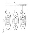
- Fig. 2.1 is a more detailed schematic of the circulating storage devices shown in Fig. 1. Shown are a plurality of disks 27 in horizontal planes. On each disk there are a number of tracks 28-1 through 28-N. Magnetic sensing units 26 which extend from arm 25 are used to read and write the data on the various tracks. Arm 25 will move to the left and right to position the sensing units 26 over the proper tracks. All the disks 27 on a given storage device, circulate as a unit at a constant speed.
- Fig. 2.2 is a schematic illustration of a top view of a disk. Shown are concentric tracks 28-1 through 28-N. The smallest quantity of data, in this embodiment, that is read out of or written into the storage device is a block 29. The data unit on the other hand can be anything from a bit to a number of blocks. The shaded area between the lines 24a and 24b is known as a sector. In this embodiment, the sectors are numbered 1 through M, and this sector number denotes the angular position on the disk of the storage device. To read data, or otherwise access data, on a given disk, a certain seek and latency time is required.
- the seek time is the time necessary for the sensing device 26 to move from a track on which it is currently located to a latter track on which data is to be accessed, easily obtained from device characteristic, as both origin and destination tracks are known.
- the latency time is the time necessary for the disk to rotate from a current sector to a latter sector where data is to be accessed, so that the latter sector of the disk is underneath the sensing device.
- the latency time for a given request may be obtained by comparing the position of the disk (determined as described below) with the known position of the data.
- each of the tracks on a given disk 27 can be divided up into, say 256 sectors, and a sector number such as n will be used to identify the angular position of information on any of these tracks. In addition to the angular position, one must also know the track on which to access or store data.
- the storage device can also be divided into a number of partitions (see 30 of Fig. 2.2), each of which may contain anything from a block to several tracks. Partition 30 of Fig. 2.2, for example, contains four blocks.
- each storage device has an associated high priority queue 31 and an associated low priority queue 32.
- Storage device 2-2 is shown only as an example. Any of the storage devices shown in Fig. 1 could have been used.
- the low priority queue 32 is used to store what is know as secondary write requests, while the high priority queue is used to store access requests or to store what is known as primary write requests.
- a read request is merely a request to read data at a particular location on an associated storage device.
- a primary write request is a request to originally store data on an associated storage device, while a secondary write request is just a request to store a copy of that data in another storage device.
- originally stored or "originally stored data” is merely used for reference purposes to distinguish it from a copy of that data that is being stored. Actually, however, duplicate data is being stored at two different storage locations. Thus, we can speak of a request to "originally store data” according to some primary write request, while a “copy of that originally stored data” is stored according to some secondary write requests.
- response time The execution time of a request from a central processing unit to read or write data in a storage device is referred to as response time. This includes queueing time in addition to service time.
- the components of the service time of a request are (1) seek, (2) latency, (3) rotational position sensing miss delay, and (4) transfer. These four components are well known in the art.
- a request is said to be serviced when data was transferred to or from the storage device in accordance with the request. That is, data stored or read in accordance with the request.
- Access time The time, that elapses between the generation of a request and the accessing of data or a location on a disk, is referred to as access time.
- access time consists of (1) queueing time, (2) seek and (3) latency. Queueing time is the time to satisfy previous unserviced requests.
- satisfying a request means that data has been written into the storage device in the case of and in accordance with a write request, or that data has been transferred from the storage device in the case of and in accordance with a read request.
- data is duplicated on at least two storage devices, preferably not on the same string.
- one of the storage devices that contains the data unit will be accessed.
- the data unit in the storage device which provides the minimum estimated access time will be accessed. This estimate is the sum of the estimates for the aforementioned three components: (1) queueing time, (2) seek and (3) latency.
- Data duplication is preferred to be on different strings so that primary and secondary write requests do not compete for the same device controller.
- satisfaction of a primary write request will be referred to as "originally storing data”, while satisfaction of a secondary write request will be referred to as storing a "copy of that originally stored data”.
- Devices are subject to failure at a rate of about three to four times per year.
- the recovery process consists of: (1) replacing the failed device by a new one, (2) restoring the data which was stored on the failed device prior to failure, and (3) updating the contents of the new device to reflect all updates which took place during the data restoration period.
- the length of the total recovery time is a very important factor in system design. A long recovery time causes the performance of the entire system to be degraded for a long period of time.
- the queue manager can be part of the central processing unit or control unit 5.
- the queue manager Since the maximum rotational delay (latency time) equals the device rotation time, i.e., 16.7 msec, in currently available DASDs, it constitutes a major component of the service time. Therefore, response time to an overall service request is effectively reduced by using seek time as one of the parameters (latency time being another parameter) for queueing control and for determining which data unit of a plurality of identical data units to access. Therefore, using the angular position as a queueing control parameter is expected to decrease response time and hence improve the overall performance of the direct access storage system.
- This simple mechanism has several advantages: (1) it does not require extra sensing or synchronization hardware components, (2) it is easily implementable in existing operating systems, and (3) it allows multiple queue managers to the same device to figure out the angular position without the need of communication or broadcasting.
- the queueing time at a particular storage device is estimated by adding the remaining service time of the request being serviced by that device to the sum of the service times of all the requests waiting in a high priority queue associated with that device. This is achieved by keeping for each storage device a tuple (t,w) where w is the total amount of service required from the device at time t.
- the tuple (t,w) provides information about the queueing time of a request joining the high priority queue associated with the device.
- the value of w decreases linearly with t, until it reaches zero when the storage device becomes idle.
- the value of (t,w) is updated every time (1) a new request joins the high priority queue and (2) an RPS miss occurs. In the first case, the amount of service required by the new request is added to w. In the second case, an additional rotation time is added to w.
Abstract
Description
- This invention relates to a method of reducing response time to I/O (Input/Output) requests to access data stored in a plurality of circulating storage devices. More specifically, data is duplicated on circulated storage devices to reduce response time.
- It is well established that information may be stored in a specific location on a storage medium and may be read out as desired. These storage media include, for example, magnetic recordings on drums, discs, or belts. The stored information may be read out by means of a transducer such as a magnetic head past which the storage medium is cyclically moved. It is also quite common that information may be requested for storage faster than the transducer can remove it from storage. This results in a plurality of requests building up at the input to the system. These requests are stored in what is known as a queue storage where they await entry to the system.
- Often, when a request is presented, the information requested is located on a storage device at a maximum distance from the transducer, and the readout cannot occur until the storage device moves the information proximate to the transducer. A delay of this type reduces the efficiency of the system and may produce an even greater backlog of requests on the queue storage.
- Several systems have been devised to eliminate this type of delay. For example, one such system provides a greater number of transducers at separate points about the storage device. Thus, information sought can be moved proximate to transducer in a shorter time. Systems of this type, however, require additional equipment such as heads, logic circuits, etc.
- Another type of system designed to eliminate this delay is described in U. S. Patent 3,350,694 to Kusnick et al. Kusnick discloses a system wherein the requests for access to data are stored in a queue in the order in which the stored information will transverse the transducer. U. S. Patent 3,437,998 to Bennett et al. describes an apparatus for selecting from all stored requests for access to data, one which identifies a storage location about to become available for accessing. Both Kusnick's and Bennett's patents provide only a single copy of data with no multipathing from the CPU (Central Processing Unit) to the data storage devices.
- It is, therefore, an object of this invention to reduce the response time to a request for access to data stored in a plurality of circulating storage devices.
- This object is solved basically in advantageous manner by applying the features laid down in the independent claims. Accordingly, the present invention discloses a method of decreasing response time to a request for access to data stored in a plurality of storage devices in a direct access storage system. With this invention, a data unit of a number of data units is stored in at least two of a plurality of storage devices. The access time is estimated for accessing a selected data unit in each of the storage devices having the selected data unit stored therein. Finally, access is requested to the selected data unit in the storage device in which the access time for accessing the selected data unit is a minimum.
- When this invention is applied to a queue request for access to data units, total response time is unexpectedly reduced by about 30% from about 30 msec to 20 msec.
- Referring now to the drawings, and more particularly to Fig. 1, there is shown a schematic of direct access storage system. Shown are circulating storage devices 2-1 through 2-n on
string 2 and storage devices 4-1 through 4-n onstring 4. Storage of data in these storage devices and access to data in these storage devices is controlled bycontrol unit 5 throughdevice controllers strings data unit 8 which is stored in two storage devices 2-2 and 4-n on different strings. An example of a control unit that could be used is an IBM 3880 Storage Control Unit. The device controller could be for example an IBM 3380 Model A4. The operation of thecontrol unit 5 and thedevice controllers - Fig. 2.1 is a more detailed schematic of the circulating storage devices shown in Fig. 1. Shown are a plurality of
disks 27 in horizontal planes. On each disk there are a number of tracks 28-1 through 28-N.Magnetic sensing units 26 which extend fromarm 25 are used to read and write the data on the various tracks.Arm 25 will move to the left and right to position thesensing units 26 over the proper tracks. All thedisks 27 on a given storage device, circulate as a unit at a constant speed. - Fig. 2.2 is a schematic illustration of a top view of a disk. Shown are concentric tracks 28-1 through 28-N. The smallest quantity of data, in this embodiment, that is read out of or written into the storage device is a
block 29. The data unit on the other hand can be anything from a bit to a number of blocks. The shaded area between thelines 24a and 24b is known as a sector. In this embodiment, the sectors are numbered 1 through M, and this sector number denotes the angular position on the disk of the storage device. To read data, or otherwise access data, on a given disk, a certain seek and latency time is required. The seek time is the time necessary for thesensing device 26 to move from a track on which it is currently located to a latter track on which data is to be accessed, easily obtained from device characteristic, as both origin and destination tracks are known. The latency time is the time necessary for the disk to rotate from a current sector to a latter sector where data is to be accessed, so that the latter sector of the disk is underneath the sensing device. The latency time for a given request may be obtained by comparing the position of the disk (determined as described below) with the known position of the data. - Thus, for example, each of the tracks on a given
disk 27 can be divided up into, say 256 sectors, and a sector number such as n will be used to identify the angular position of information on any of these tracks. In addition to the angular position, one must also know the track on which to access or store data. The storage device can also be divided into a number of partitions (see 30 of Fig. 2.2), each of which may contain anything from a block to several tracks.Partition 30 of Fig. 2.2, for example, contains four blocks. - Referring now to Fig. 3, each storage device has an associated
high priority queue 31 and an associatedlow priority queue 32. Storage device 2-2 is shown only as an example. Any of the storage devices shown in Fig. 1 could have been used. Thelow priority queue 32 is used to store what is know as secondary write requests, while the high priority queue is used to store access requests or to store what is known as primary write requests. A read request is merely a request to read data at a particular location on an associated storage device. A primary write request is a request to originally store data on an associated storage device, while a secondary write request is just a request to store a copy of that data in another storage device. The term "originally stored" or "originally stored data" is merely used for reference purposes to distinguish it from a copy of that data that is being stored. Actually, however, duplicate data is being stored at two different storage locations. Thus, we can speak of a request to "originally store data" according to some primary write request, while a "copy of that originally stored data" is stored according to some secondary write requests. - In this application, the term "write" will be used synonymously with the term "store".
- The execution time of a request from a central processing unit to read or write data in a storage device is referred to as response time. This includes queueing time in addition to service time. The components of the service time of a request are (1) seek, (2) latency, (3) rotational position sensing miss delay, and (4) transfer. These four components are well known in the art. A request is said to be serviced when data was transferred to or from the storage device in accordance with the request. That is, data stored or read in accordance with the request.
- Data is said to be accessed when the transducer is proximate to the data so that the data can be read. Accessing also means that the transducer is proximate to a location on the disk so that data can be written at that location. The time, that elapses between the generation of a request and the accessing of data or a location on a disk, is referred to as access time. Thus, access time consists of (1) queueing time, (2) seek and (3) latency. Queueing time is the time to satisfy previous unserviced requests.
- In this application satisfying a request means that data has been written into the storage device in the case of and in accordance with a write request, or that data has been transferred from the storage device in the case of and in accordance with a read request.
- In the operation of the invention to reduce response time, data is duplicated on at least two storage devices, preferably not on the same string. At a later time when there is a request to access a particular data unit that has been previously stored, one of the storage devices that contains the data unit will be accessed. The data unit in the storage device which provides the minimum estimated access time will be accessed. This estimate is the sum of the estimates for the aforementioned three components: (1) queueing time, (2) seek and (3) latency.
- In this embodiment, when there is a request to store a data unit, two requests to store that same data unit are generated by the central processing unit. Such requests will specify storage in a different storage device than the other request. The access time for each of the two requests will be estimated as described below. The request requiring the lesser estimated access time is known as the primary write request, and this request will be stored in a high priority queue of an associated storage device that is specified by the primary write request. The request requiring a greater access time is known as the secondary write request, and this request is stored in a low priority queue associated with the storage device that is requested by the secondary write request. Thus, for any given storage device requests in the associated high priority queue is serviced before any request in the associated low priority queue. Thus, for any given storage device primary write requests and read requests will be satisfied before any secondary write request is satisfied. Thus for any given storage device read requests will not be delayed on account of duplicating storage.
- Data duplication is preferred to be on different strings so that primary and secondary write requests do not compete for the same device controller.
- In the above paragraph, satisfaction of a primary write request will be referred to as "originally storing data", while satisfaction of a secondary write request will be referred to as storing a "copy of that originally stored data".
- As far as the storage of duplicated data is concerned, we differentiate between two storage schemes: (1) Mirrored devices and (2) Non-Mirrored devices. In the first scheme, data on one device is entirely duplicated on another device. These two devices are called paired since they contain the same data. Alternatively, one could divide the data on one device into a number of partitions and store the duplicate of these partitions such that each duplicate partition is stored on a different device. We refer to this storage scheme as non-mirrored.
- Devices are subject to failure at a rate of about three to four times per year. In the case of a device failure, the recovery process consists of: (1) replacing the failed device by a new one, (2) restoring the data which was stored on the failed device prior to failure, and (3) updating the contents of the new device to reflect all updates which took place during the data restoration period. The length of the total recovery time is a very important factor in system design. A long recovery time causes the performance of the entire system to be degraded for a long period of time.
- Consider a case of a device failure in both a mirrored and a non-mirrored environment. In a mirrored environment, data is restored by reading the contents of the mirrored device of the failed device and copying it on to the new device. This process results in traffic contention at the mirrored device since all the copying requests as well as read and write requests during recovery are served by a single resource. On the other hand, copying in a non-mirrored environment could be done in parallel since the data to be restored is stored on physically different devices. Hence, the load of copying is distributed among more than one resource. In addition, read traffic during recovery could be redirected in order to balance the load on devices and thus improve performance.
- Therefore, we suggest storing duplicated data on non-mirrored devices so that the recovery time is minimized. By analyzing a direct access storage system with two strings of 8 3380 devices, we found that, if devices are mirrored, the recovery time is approximately 40 minutes when the channel is utilized 30% of the time. In a non-mirrored environment and with two-way recovery, i.e. data on a device is divided into two partitions, the recovery times goes down to approximately 15 minutes. This time amounts to a decrease of about 60% in the recovery time when compared to the mirrored case. We have also found that the recovery time may be decreased even further by having more than two partitions.
- Information about the seek time is available to the queue manager since each request specifies the arm position that it needs. Accordingly, the manager knows exactly the arm position, and hence the seek time, of the device and can use that information to schedule requests to minimize the seek time component of service. The queue manager can be part of the central processing unit or
control unit 5. - Here, we are concerned with providing information about the latency time for service, namely the angular position of the device, to the queue manager. Since the maximum rotational delay (latency time) equals the device rotation time, i.e., 16.7 msec, in currently available DASDs, it constitutes a major component of the service time. Therefore, response time to an overall service request is effectively reduced by using seek time as one of the parameters (latency time being another parameter) for queueing control and for determining which data unit of a plurality of identical data units to access. Therefore, using the angular position as a queueing control parameter is expected to decrease response time and hence improve the overall performance of the direct access storage system. One way of determining the angular position of a device is through the addition of hardware components that will either synchronize devices on a string or monitor rotation via a sensing and feedback mechanism. This approach results in a more complex and expensive system. Our invention yields an estimate of the angular position without having to add any hardware components.
- Let us consider a queue of access requests. After a storage location is accessed, data is then stored or read. In particular, consider a request with specified sector number n, n = 0,1..., M - 1, where M is the number of sectors per track. Let t be the completion time, i.e. channel connect time, for that request. Then, it is clear that the device is positioned at sector n at time t. The tuple (t,n) provides information about the angular position of the device at any time T. More specifically, the sector number a time T is given by the simple expression,
[n + (T - t)] mod M
where x is the device rotation time. The queue manager needs only to store the most recent tuple (t,n) and uses the clock time T to determine the angular position at that time. - This simple mechanism has several advantages: (1) it does not require extra sensing or synchronization hardware components, (2) it is easily implementable in existing operating systems, and (3) it allows multiple queue managers to the same device to figure out the angular position without the need of communication or broadcasting.
- The queueing time at a particular storage device is estimated by adding the remaining service time of the request being serviced by that device to the sum of the service times of all the requests waiting in a high priority queue associated with that device. This is achieved by keeping for each storage device a tuple (t,w) where w is the total amount of service required from the device at time t. The tuple (t,w) provides information about the queueing time of a request joining the high priority queue associated with the device. The value of w decreases linearly with t, until it reaches zero when the storage device becomes idle. The value of (t,w) is updated every time (1) a new request joins the high priority queue and (2) an RPS miss occurs. In the first case, the amount of service required by the new request is added to w. In the second case, an additional rotation time is added to w.
Claims (7)
[ n + (T - t)
where x is the rotation time, n is the angular position of the mechanism at time t, and M is the number of sectors per track.
Applications Claiming Priority (2)
| Application Number | Priority Date | Filing Date | Title |
|---|---|---|---|
| US92595386A | 1986-11-03 | 1986-11-03 | |
| US925953 | 1986-11-03 |
Publications (2)
| Publication Number | Publication Date |
|---|---|
| EP0266586A2 true EP0266586A2 (en) | 1988-05-11 |
| EP0266586A3 EP0266586A3 (en) | 1992-11-25 |
Family
ID=25452482
Family Applications (1)
| Application Number | Title | Priority Date | Filing Date |
|---|---|---|---|
| EP19870114910 Withdrawn EP0266586A3 (en) | 1986-11-03 | 1987-10-13 | Decreasing response time to i/o request by duplicating data |
Country Status (2)
| Country | Link |
|---|---|
| EP (1) | EP0266586A3 (en) |
| JP (1) | JPS63124269A (en) |
Cited By (9)
| Publication number | Priority date | Publication date | Assignee | Title |
|---|---|---|---|---|
| EP0426184A2 (en) * | 1989-11-03 | 1991-05-08 | Compaq Computer Corporation | Bus master command protocol |
| EP0437615A1 (en) * | 1989-06-14 | 1991-07-24 | Hitachi, Ltd. | Hierarchical presearch-type document retrieval method, apparatus therefor, and magnetic disc device for this apparatus |
| EP0606139A2 (en) * | 1993-01-04 | 1994-07-13 | Xerox Corporation | Dispatching and scheduling memory operations in an electronic printing system |
| US5454105A (en) * | 1989-06-14 | 1995-09-26 | Hitachi, Ltd. | Document information search method and system |
| EP0682314A2 (en) * | 1994-04-14 | 1995-11-15 | International Business Machines Corporation | Redundant disk storage system |
| US5471610A (en) * | 1989-06-14 | 1995-11-28 | Hitachi, Ltd. | Method for character string collation with filtering function and apparatus |
| EP0675429A3 (en) * | 1988-11-11 | 1996-06-12 | Victor Company Of Japan | Data handling apparatus. |
| US5748953A (en) * | 1989-06-14 | 1998-05-05 | Hitachi, Ltd. | Document search method wherein stored documents and search queries comprise segmented text data of spaced, nonconsecutive text elements and words segmented by predetermined symbols |
| US5757983A (en) * | 1990-08-09 | 1998-05-26 | Hitachi, Ltd. | Document retrieval method and system |
Citations (3)
| Publication number | Priority date | Publication date | Assignee | Title |
|---|---|---|---|---|
| GB1436332A (en) * | 1973-01-25 | 1976-05-19 | Honeywell Inf Systems | Magnetic disc storage systems |
| EP0133706A2 (en) * | 1983-08-11 | 1985-03-06 | Lucas Film, Ltd. | Method and system for storing and retrieving multiple channel sampled data |
| GB2168176A (en) * | 1984-12-05 | 1986-06-11 | Philips Nv | Addressing data stored on multiple discs |
Family Cites Families (1)
| Publication number | Priority date | Publication date | Assignee | Title |
|---|---|---|---|---|
| JPS5757357A (en) * | 1980-09-25 | 1982-04-06 | Nec Corp | Multiplex magnetic disk system |
-
1987
- 1987-09-17 JP JP62231253A patent/JPS63124269A/en active Pending
- 1987-10-13 EP EP19870114910 patent/EP0266586A3/en not_active Withdrawn
Patent Citations (3)
| Publication number | Priority date | Publication date | Assignee | Title |
|---|---|---|---|---|
| GB1436332A (en) * | 1973-01-25 | 1976-05-19 | Honeywell Inf Systems | Magnetic disc storage systems |
| EP0133706A2 (en) * | 1983-08-11 | 1985-03-06 | Lucas Film, Ltd. | Method and system for storing and retrieving multiple channel sampled data |
| GB2168176A (en) * | 1984-12-05 | 1986-06-11 | Philips Nv | Addressing data stored on multiple discs |
Cited By (15)
| Publication number | Priority date | Publication date | Assignee | Title |
|---|---|---|---|---|
| EP0675429A3 (en) * | 1988-11-11 | 1996-06-12 | Victor Company Of Japan | Data handling apparatus. |
| US5471610A (en) * | 1989-06-14 | 1995-11-28 | Hitachi, Ltd. | Method for character string collation with filtering function and apparatus |
| EP0437615A1 (en) * | 1989-06-14 | 1991-07-24 | Hitachi, Ltd. | Hierarchical presearch-type document retrieval method, apparatus therefor, and magnetic disc device for this apparatus |
| EP0437615A4 (en) * | 1989-06-14 | 1993-06-02 | Hitachi, Ltd. | Hierarchical presearch-type document retrieval method, apparatus therefor, and magnetic disc device for this apparatus |
| US5748953A (en) * | 1989-06-14 | 1998-05-05 | Hitachi, Ltd. | Document search method wherein stored documents and search queries comprise segmented text data of spaced, nonconsecutive text elements and words segmented by predetermined symbols |
| US5519857A (en) * | 1989-06-14 | 1996-05-21 | Hitachi, Ltd. | Hierarchical presearch type text search method and apparatus and magnetic disk unit used in the apparatus |
| US5454105A (en) * | 1989-06-14 | 1995-09-26 | Hitachi, Ltd. | Document information search method and system |
| EP0426184A3 (en) * | 1989-11-03 | 1993-07-28 | Compaq Computer Corporation | Bus master command protocol |
| EP0426184A2 (en) * | 1989-11-03 | 1991-05-08 | Compaq Computer Corporation | Bus master command protocol |
| US5757983A (en) * | 1990-08-09 | 1998-05-26 | Hitachi, Ltd. | Document retrieval method and system |
| EP0606139A3 (en) * | 1993-01-04 | 1995-01-18 | Xerox Corp | Dispatching and scheduling memory operations in an electronic printing system. |
| EP0606139A2 (en) * | 1993-01-04 | 1994-07-13 | Xerox Corporation | Dispatching and scheduling memory operations in an electronic printing system |
| EP0682314A2 (en) * | 1994-04-14 | 1995-11-15 | International Business Machines Corporation | Redundant disk storage system |
| EP0682314A3 (en) * | 1994-04-14 | 1996-03-20 | Ibm | Redundant disk storage system. |
| US5887128A (en) * | 1994-04-14 | 1999-03-23 | International Business Machines Corporation | Method and apparatus for redundant disk storage system with offset |
Also Published As
| Publication number | Publication date |
|---|---|
| EP0266586A3 (en) | 1992-11-25 |
| JPS63124269A (en) | 1988-05-27 |
Similar Documents
| Publication | Publication Date | Title |
|---|---|---|
| JP3287203B2 (en) | External storage controller and data transfer method between external storage controllers | |
| US6948042B2 (en) | Hierarchical storage apparatus and control apparatus thereof | |
| US5239640A (en) | Data storage system and method including data and checksum write staging storage | |
| JP3541744B2 (en) | Storage subsystem and control method thereof | |
| US6230239B1 (en) | Method of data migration | |
| US6272571B1 (en) | System for improving the performance of a disk storage device by reconfiguring a logical volume of data in response to the type of operations being performed | |
| US4607346A (en) | Apparatus and method for placing data on a partitioned direct access storage device | |
| JP3181446B2 (en) | Information storage device | |
| JP3735571B2 (en) | Method and system for dynamically selecting a tape drive for connection to a host computer | |
| US20080320218A1 (en) | Disk array apparatus and control method for disk array apparatus | |
| US6260109B1 (en) | Method and apparatus for providing logical devices spanning several physical volumes | |
| JPH0683687A (en) | Data processing system and method thereof | |
| US7039657B1 (en) | Method, system, and program for accessing data from storage systems | |
| EP0266586A2 (en) | Decreasing response time to I/O request by duplicating data | |
| EP1760590B1 (en) | Storage controller system having a splitting command for paired volumes and method therefor | |
| JPH07225715A (en) | Method and system for accessing data in cache | |
| JPH06131233A (en) | Access method and library device for multi-file type storage medium | |
| JP2000187608A (en) | Storage device sub-system | |
| US20020199038A1 (en) | Input/output control apparatus, input/output control method and informatiion storage system | |
| CN102576294B (en) | Storage system and method comprising a plurality of storage devices | |
| KR100292700B1 (en) | Method for managing files in library and server device for library | |
| JPH10269026A (en) | Library sub system | |
| US20050086249A1 (en) | Method for logical volume conversions | |
| US5875453A (en) | Apparatus for and method of information processing | |
| JPH10254645A (en) | Storage device and storage device subsystem |
Legal Events
| Date | Code | Title | Description |
|---|---|---|---|
| PUAI | Public reference made under article 153(3) epc to a published international application that has entered the european phase |
Free format text: ORIGINAL CODE: 0009012 |
|
| AK | Designated contracting states |
Kind code of ref document: A2 Designated state(s): DE FR GB IT |
|
| 17P | Request for examination filed |
Effective date: 19880910 |
|
| PUAL | Search report despatched |
Free format text: ORIGINAL CODE: 0009013 |
|
| AK | Designated contracting states |
Kind code of ref document: A3 Designated state(s): DE FR GB IT |
|
| STAA | Information on the status of an ep patent application or granted ep patent |
Free format text: STATUS: THE APPLICATION IS DEEMED TO BE WITHDRAWN |
|
| 18D | Application deemed to be withdrawn |
Effective date: 19930525 |
|
| RIN1 | Information on inventor provided before grant (corrected) |
Inventor name: FRANASZEK, PETER ANTHONY Inventor name: TANTAWI, ASSER NASRELDIN |