EP0268089A2 - Passive transponder - Google Patents
Passive transponder Download PDFInfo
- Publication number
- EP0268089A2 EP0268089A2 EP87115247A EP87115247A EP0268089A2 EP 0268089 A2 EP0268089 A2 EP 0268089A2 EP 87115247 A EP87115247 A EP 87115247A EP 87115247 A EP87115247 A EP 87115247A EP 0268089 A2 EP0268089 A2 EP 0268089A2
- Authority
- EP
- European Patent Office
- Prior art keywords
- transponder
- bases
- antenna elements
- electronic component
- conductor
- Prior art date
- Legal status (The legal status is an assumption and is not a legal conclusion. Google has not performed a legal analysis and makes no representation as to the accuracy of the status listed.)
- Granted
Links
Images
Classifications
-
- G—PHYSICS
- G01—MEASURING; TESTING
- G01S—RADIO DIRECTION-FINDING; RADIO NAVIGATION; DETERMINING DISTANCE OR VELOCITY BY USE OF RADIO WAVES; LOCATING OR PRESENCE-DETECTING BY USE OF THE REFLECTION OR RERADIATION OF RADIO WAVES; ANALOGOUS ARRANGEMENTS USING OTHER WAVES
- G01S13/00—Systems using the reflection or reradiation of radio waves, e.g. radar systems; Analogous systems using reflection or reradiation of waves whose nature or wavelength is irrelevant or unspecified
- G01S13/74—Systems using reradiation of radio waves, e.g. secondary radar systems; Analogous systems
- G01S13/75—Systems using reradiation of radio waves, e.g. secondary radar systems; Analogous systems using transponders powered from received waves, e.g. using passive transponders, or using passive reflectors
- G01S13/751—Systems using reradiation of radio waves, e.g. secondary radar systems; Analogous systems using transponders powered from received waves, e.g. using passive transponders, or using passive reflectors wherein the responder or reflector radiates a coded signal
- G01S13/753—Systems using reradiation of radio waves, e.g. secondary radar systems; Analogous systems using transponders powered from received waves, e.g. using passive transponders, or using passive reflectors wherein the responder or reflector radiates a coded signal using frequency selective elements, e.g. resonator
-
- H—ELECTRICITY
- H01—ELECTRIC ELEMENTS
- H01Q—ANTENNAS, i.e. RADIO AERIALS
- H01Q9/00—Electrically-short antennas having dimensions not more than twice the operating wavelength and consisting of conductive active radiating elements
- H01Q9/04—Resonant antennas
- H01Q9/06—Details
- H01Q9/065—Microstrip dipole antennas
-
- H—ELECTRICITY
- H01—ELECTRIC ELEMENTS
- H01Q—ANTENNAS, i.e. RADIO AERIALS
- H01Q9/00—Electrically-short antennas having dimensions not more than twice the operating wavelength and consisting of conductive active radiating elements
- H01Q9/04—Resonant antennas
- H01Q9/16—Resonant antennas with feed intermediate between the extremities of the antenna, e.g. centre-fed dipole
- H01Q9/26—Resonant antennas with feed intermediate between the extremities of the antenna, e.g. centre-fed dipole with folded element or elements, the folded parts being spaced apart a small fraction of operating wavelength
Definitions
- the present invention relates to a passive transponder comprising two antenna elements connected by a non-linear electronic component and by a conductor arranged in parallel with the passive electronic component.
- transponder is described, for example, in patent application EP-A-0 172 445.
- antenna elements each consist of a thin metal plate having for example a substantially rectangular shape.
- the passive electronic component which connects the two antenna elements is, for example, a diode with quadratic current-voltage characteristic such as the diode sold under the number 5 082-2835 by the company Hewlett-Packard.
- Such a transponder is in particular intended to be carried by a person running the risk of being taken under an avalanche. If such an accident occurs, this person can be located using a suitable detection device brought nearby and comprising a transmitter producing electromagnetic radiation having a wavelength substantially equal to twice the total length of the transponder.
- the transponder When subjected to this electromagnetic radiation, the transponder emits a second electromagnetic radiation having a wavelength substantially equal to its total length and therefore substantially equal to half the wavelength of the radiation produced by the transmitter.
- This second electromagnetic radiation can be picked up by a suitable receiver which also includes the detection device, which makes it possible to locate the transponder and therefore the person carrying it.
- the various components of the transponder form an oscillating circuit whose resonant frequency must be as close as possible to the frequency of the electromagnetic radiation emitted by the detection device in order for the efficiency of the transponder, that is to say the ratio between the quantity of energy which it emits and that which it receives, is high.
- the metal plates constituting the antenna elements of the transponder form with the body of the person carrying it a parasitic capacitor whose capacity influences the resonance frequency of the oscillating circuit mentioned above.
- the resonance frequency of the oscillating circuit formed by the elements of the transponder is therefore almost never equal to the frequency of the electromagnetic radiation emitted by the detection device, and the efficiency of the transponder is therefore almost never optimum.
- this parasitic capacitor diverts towards the body of the person carrying the transponder part of the energy received by the latter and part of the energy which it emits, which also causes a reduction in the efficiency of the transponder.
- An object of the present invention is to provide a transponder of the kind which has been described above, but which has a higher efficiency than this known transponder.
- each of the antenna elements of the transponder according to the invention consists of a metallic strip forming in its plane a loop surrounding a space devoid of any metallic element.
- the resonant frequency of the oscillating circuit formed by the various components of the transponder is therefore much less influenced by the capacity of this parasitic capacitor. This resonance frequency is therefore always much closer to that of the electromagnetic radiation emitted by the detection device, and the efficiency of the transponder according to the invention is therefore better than that of the known transponder.
- the shape of the loops constituting the antenna elements and the shape of the opening delimited by these antenna elements, by the non-linear passive electronic component and by the conductor connecting the two antenna elements also have an influence on the performance of the transponder as well as, for the same form of transponder, on the variation of this performance from one copy to another.
- This influence is probably due to the fact that if the impedances of the various components of the transponder are not at least substantially equal at the points where these components are connected to each other, this results in energy losses due to the reflections which occur in these points.
- Another object of the present invention is to provide a transponder in which the shape of the loops constituting the antenna elements and the shape of the opening delimited by these antenna elements, the passive electronic component and the conductor connecting the two elements antenna are chosen so that the performance of the transponder is further improved, and that this performance is more constant from one copy to another.
- the loops constituting the antenna elements have the general shape of rectangular trapezoids whose small bases are arranged opposite one another and parallel to each other, the passive electronic component being connected between these small bases, and whose sides perpendicular to the bases are aligned one on the other and are connected by a conductive portion also constituted by a metallic strip, having a width less than the width of said perpendicular sides at the bases and arranged so that its outer edge is aligned with the outer edge of said sides perpendicular to the bases, and thanks to the fact that said sides of the trapezoids perpendicular to the bases each have a rectilinear slot extending parallel to their length, closed on the side of the large base and open on the side of the small base near said conductive portion, said conductor thus being constituted by the parts of the sides of the trapezoids perpendicular to the bases which are situated outside said slots and by said conductive portion, and the space delimited by the antenna elements, the passive electronic component and the conductor having substantially the
- the transponder according to the invention comprises two antenna elements 1 and 2 having a general shape of rectangles arranged in the extension of one another.
- Diode 3 can be, for example, a diode with quadratic current-voltage characteristic such as the diode sold under the number 5 082-2835 by the company Hewlett -Packard.
- the sides 1a and 2a of the antenna elements 1 and 2, the diode 3 and the conductor 4 thus define a central opening 5 of substantially circular shape in this example.
- the antenna elements 1 and 2 are each pierced with an opening 6, respectively 7, the edges of which are substantially parallel to the edges of the antenna elements 1 and 2.
- the various components of the transponder are fixed on a support made of a dielectric material which has not been shown because it can be of any shape.
- the surface of the metal parts of the transponder according to the invention in particular the surface of the antenna elements 1 and 2 is much smaller than the surface of the metal parts of the transponder described in the above patent application, thanks to the fact that these antenna elements have the general form of a closed loop surrounding a space devoid of any metallic element.
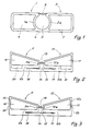
- the transponder according to the invention comprises, like the transponder of Figure 1, two antenna elements, designated by 11 and 12, which are connected on the one hand by a diode , designated by 13, and by a conductor, designated by 14.
- the diode 13 can be of the same kind as the diode 3 of the transponder of FIG. 1.
- the antenna elements 11 and 12 are each pierced with a central opening designated respectively by 16 and 17. These antenna elements 11 and 12 therefore also have the general shape of a loop surrounding a space devoid of any metallic element, which gives the transponder of FIG. 2 the same advantages compared to the known transponder as in the case of FIG. 1.
- the loops constituting the antenna elements 11 and 12 have a general shape of a rectangular trapezoid.
- the small bases 11a and 12a of these trapezoids are arranged opposite one another and parallel to each other, and are connected by the diode 13.
- the sides 11b and 12b of the trapezoids formed by the antenna elements 11 and 12 and which are perpendicular to the bases 11a and 12a are aligned one on the other.
- These sides 11b and 12b each have a slot 18, respectively 19, which extends over part of their length parallel to this length, which is closed on the side of the large bases 11c and 12c of the trapezoids, and which opens on the space separating the small bases 11a and 12a.
- the conductor 14 is thus formed by the outer parts of the sides 11b and 12b, separated from the rest of these sides by the slots 18 and 19, extended and connected to each other by a conductive connecting portion.
- the space 15 delimited by the antenna elements 11 and 12, the diode 13 and the conductor 14 therefore has substantially the shape of a T whose horizontal bar is formed by the slots 18 and 19 and the vertical bar is formed by the space separating the two small bases 11a and 12a between the diode 13 and the conductor 14.
- the antenna elements 11 and 12 and the conductor 14 of the transponder of FIG. 2 are cut from a thin metal sheet and fixed to a support made of suitable dielectric material. who was not represented.
- FIG. 2 also represents a variant of the embodiment of the transponder according to the invention which has just been described.
- the sides 11b and 12b of the antenna elements 11 and 12 are cut along the lines drawn in lines mixed in Figure 2, and the parts designated by 20 and 21 are eliminated. This results in a reduction in the surface of the metal parts of the antenna elements 11 and 12, and therefore in an increase in the efficiency of the transponder, for the same reasons as those which have been mentioned above.
- the transponder shown in FIG. 3 has the same general shape and has the same elements as that of FIG. 2.
- transponders lies in the presence of transverse slots 22 and 23 which intersect respectively the large bases 11 c and 12 c of the antenna elements 11 and 12 of the transponder of FIG. 3.
Abstract
Description
La présente invention a pour objet un transpondeur passif comportant deux éléments d'antenne reliés par un composant électronique non linéaire et par un conducteur disposé en parallèle avec le composant électronique passif.The present invention relates to a passive transponder comprising two antenna elements connected by a non-linear electronic component and by a conductor arranged in parallel with the passive electronic component.
Un tel transpondeur est décrit, par exemple, dans la demande de brevet EP-A-0 172 445.Such a transponder is described, for example, in patent application EP-A-0 172 445.
Ses deux éléments d'antenne sont constitués chacun par une plaque métallique mince ayant par exemple une forme sensiblement rectangulaire.Its two antenna elements each consist of a thin metal plate having for example a substantially rectangular shape.
Le composant électronique passif qui relie les deux éléments d'antenne est, par exemple, une diode à caractéristique courant-tension quadratique telle que la diode vendue sous le numéro 5 082-2835 par la société Hewlett-Packard.The passive electronic component which connects the two antenna elements is, for example, a diode with quadratic current-voltage characteristic such as the diode sold under the
Un tel transpondeur est notamment destiné à être porté par une personne courant le risque d'être prise sous une avalanche. Si un tel accident arrive, cette personne peut être localisée à l'aide d'un appareil de détection adéquat amené à proximité et comportant un émetteur produisant un rayonnement électromagnétique ayant une longueur d'onde sensiblement égale au double de la longueur totale du transpondeur.Such a transponder is in particular intended to be carried by a person running the risk of being taken under an avalanche. If such an accident occurs, this person can be located using a suitable detection device brought nearby and comprising a transmitter producing electromagnetic radiation having a wavelength substantially equal to twice the total length of the transponder.
Lorsqu'il est soumis à ce rayonnement électromagnétique, le transpondeur émet un deuxième rayonnement électromagnétique ayant une longueur d'onde sensiblement égale à sa longueur totale et donc sensiblement égale à la moitié de la longueur d'onde du rayonnement produit par l'émetteur. Ce deuxième rayonnement électromagnétique peut être capté par un récepteur adéquat que comporte également l'appareil de détection, ce qui permet de localiser le transpondeur et donc la personne qui le porte.When subjected to this electromagnetic radiation, the transponder emits a second electromagnetic radiation having a wavelength substantially equal to its total length and therefore substantially equal to half the wavelength of the radiation produced by the transmitter. This second electromagnetic radiation can be picked up by a suitable receiver which also includes the detection device, which makes it possible to locate the transponder and therefore the person carrying it.
Les divers composants du transpondeur forment un circuit oscillant dont la fréquence de résonance doit être aussi proche que possible de la fréquence du rayonnement électromagnétique émis par l'appareil de détection pour que le rendement du transpondeur, c'est-à-dire le rapport entre la quantité d'énergie qu'il émet et celle qu'il reçoit, soit élevé.The various components of the transponder form an oscillating circuit whose resonant frequency must be as close as possible to the frequency of the electromagnetic radiation emitted by the detection device in order for the efficiency of the transponder, that is to say the ratio between the quantity of energy which it emits and that which it receives, is high.
Or, les plaques métalliques constituant les éléments d'antenne du transpondeur forment avec le corps de la personne qui porte celui-ci un condensateur parasite dont la capacité influence la fréquence de résonance du circuit oscillant mentionné ci-dessus.However, the metal plates constituting the antenna elements of the transponder form with the body of the person carrying it a parasitic capacitor whose capacity influences the resonance frequency of the oscillating circuit mentioned above.
Il n'est pas possible de compenser l'effet de ce condensateur parasite par un dimensionnement adéquat des autres composants du transpondeur, car sa capacité dépend directement de la distance séparant ce transpondeur du corps de la personne qui le porte, et que cette distance est variable selon que ce transpondeur est porté sur une ou plusieurs couches de vêtements.It is not possible to compensate for the effect of this parasitic capacitor by an adequate dimensioning of the other components of the transponder, because its capacity depends directly on the distance separating this transponder from the body of the person carrying it, and that this distance is variable depending on whether this transponder is worn on one or more layers of clothing.
La fréquence de résonance du circuit oscillant formé par les éléments du transpondeur n'est donc pratiquement jamais égale à la fréquence du rayonnement électromagnétique émis par l'appareil de détection, et le rendement du transpondeur n'est donc pratiquement jamais optimum.The resonance frequency of the oscillating circuit formed by the elements of the transponder is therefore almost never equal to the frequency of the electromagnetic radiation emitted by the detection device, and the efficiency of the transponder is therefore almost never optimum.
En outre, ce condensateur parasite détourne vers le corps de la personne portant le transpondeur une partie de l'énergie reçue par ce dernier et une partie de l'énergie qu'il émet, ce qui provoque également une diminution du rendement du transpondeur.In addition, this parasitic capacitor diverts towards the body of the person carrying the transponder part of the energy received by the latter and part of the energy which it emits, which also causes a reduction in the efficiency of the transponder.
Un but de la présente invention est de proposer un transpondeur du genre de celui qui a été décrit ci-dessus, mais qui présente un rendement plus élevé que ce transpondeur connu.An object of the present invention is to provide a transponder of the kind which has been described above, but which has a higher efficiency than this known transponder.
Ce but est atteint grâce au fait que chacun des éléments d'antenne du transpondeur selon l'invention est constitué par un ruban métallique formant dans son plan une boucle entourant un espace dépourvu de tout élément métallique.This object is achieved thanks to the fact that each of the antenna elements of the transponder according to the invention consists of a metallic strip forming in its plane a loop surrounding a space devoid of any metallic element.
Il résulte de cette caractéristique que, à dimensions égales, la capacité du condensateur formé par les éléments d'antenne et le corps de la personne portant le transpondeur est beaucoup plus faible que dans le transpondeur de l'art antérieur.It follows from this characteristic that, for equal dimensions, the capacitance of the capacitor formed by the antenna elements and the body of the person carrying the transponder is much lower than in the transponder of the prior art.
La fréquence de résonance du circuit oscillant formé par les divers composants du transpondeur est donc beaucoup moins influencée par la capacité de ce condensateur parasite. Cette fréquence de résonance est donc toujours beaucoup plus proche de celle du rayonnement électromagnétique émis par l'appareil de détection, et le rendement du transpondeur selon l'invention est donc meilleur que celui du transpondeur connu.The resonant frequency of the oscillating circuit formed by the various components of the transponder is therefore much less influenced by the capacity of this parasitic capacitor. This resonance frequency is therefore always much closer to that of the electromagnetic radiation emitted by the detection device, and the efficiency of the transponder according to the invention is therefore better than that of the known transponder.
La quantité d'énergie transmise par ce condensateur parasite au corps de la personne portant le transpondeur selon l'invention est également diminuée, ce qui augmente encore son rendement.The amount of energy transmitted by this parasitic capacitor to the body of the person carrying the transponder according to the invention is also reduced, which further increases its efficiency.
Il a été constaté que la forme des boucles constituant les éléments d'antenne et la forme de l'ouverture délimitée par ces éléments d'antenne, par le composant électronique passif non linéaire et par le conducteur reliant les deux éléments d'antenne ont également une influence sur le rendement du transpondeur ainsi que, pour la même forme de transpondeur, sur la variation de ce rendement d'un exemplaire à l'autre. Cette influence est probablement due au fait que si les impédances des divers composants du transpondeur ne sont pas au moins sensiblement égales aux points où ces composants sont connectés les uns aux autres, il en résulte des pertes d'énergie dues aux réflexions qui se produisent en ces points.It was found that the shape of the loops constituting the antenna elements and the shape of the opening delimited by these antenna elements, by the non-linear passive electronic component and by the conductor connecting the two antenna elements also have an influence on the performance of the transponder as well as, for the same form of transponder, on the variation of this performance from one copy to another. This influence is probably due to the fact that if the impedances of the various components of the transponder are not at least substantially equal at the points where these components are connected to each other, this results in energy losses due to the reflections which occur in these points.
Un autre but de la présente invention est de proposer un transpondeur dans lequel la forme des boucles constituant les éléments d'antenne et la forme de l'ouverture délimitée par ces éléments d'antenne, le composant électronique passif et le conducteur reliant les deux éléments d'antenne sont choisies de manière que le rendement du transpondeur soit encore amélioré, et que ce rendement soit plus constant d'un exemplaire à l'autre.
Cet autre but est atteint grâce au fait que les boucles constituant les éléments d'antenne ont la forme générale de trapèzes rectangles dont les petites bases sont disposées en regard l'une de l'autre et parallèlement l'une à l'autre, le composant électronique passif étant branché entre ces petites bases, et dont les côtés perpendiculaires aux bases sont alignés l'un sur l'autre et sont reliés par une portion conductrice également constituée par un ruban métallique, ayant une largeur inférieure à la largeur desdits côtés perpendiculaires aux bases et disposée de manière que son bord extérieur soit aligné sur le bord extérieur desdits côtés perpendiculaires aux bases, et grâce au fait que lesdits côtés des trapèzes perpendiculaires aux bases comportent chacun une fente rectiligne s'étendant parallèlement à leur longueur, fermée du côté de la grande base et ouverte du côté de la petite base à proximité de ladite portion conductrice, ledit conducteur étant ainsi constitué par les parties des côtés des trapèzes perpendiculaires aux bases qui sont situées à l'extérieur desdites fentes et par ladite portion conductrice, et l'espace délimité par les éléments d'antenne, le composant électronique passif et le conducteur ayant sensiblement la forme d'un T dont la barre horizontale est constituée par lesdites fentes et dont la barre verticale est constituée par l'espace séparant les petites bases entre le composant électronique passif et le conducteur.Another object of the present invention is to provide a transponder in which the shape of the loops constituting the antenna elements and the shape of the opening delimited by these antenna elements, the passive electronic component and the conductor connecting the two elements antenna are chosen so that the performance of the transponder is further improved, and that this performance is more constant from one copy to another.
This other object is achieved thanks to the fact that the loops constituting the antenna elements have the general shape of rectangular trapezoids whose small bases are arranged opposite one another and parallel to each other, the passive electronic component being connected between these small bases, and whose sides perpendicular to the bases are aligned one on the other and are connected by a conductive portion also constituted by a metallic strip, having a width less than the width of said perpendicular sides at the bases and arranged so that its outer edge is aligned with the outer edge of said sides perpendicular to the bases, and thanks to the fact that said sides of the trapezoids perpendicular to the bases each have a rectilinear slot extending parallel to their length, closed on the side of the large base and open on the side of the small base near said conductive portion, said conductor thus being constituted by the parts of the sides of the trapezoids perpendicular to the bases which are situated outside said slots and by said conductive portion, and the space delimited by the antenna elements, the passive electronic component and the conductor having substantially the shape of a T whose horizontal bar is formed by said slots and whose vertical bar is formed by the space separating the small bases between the passive electronic component and the conductor.
La présente invention sera mieux comprise à l'aide de la description qui va suivre et des dessins qui l'illustrent à titre d'exemples non limitatifs. Dans ces dessins,
- - la figure 1 est une vue schématique en plan d'une première forme d'exécution du transpondeur selon l'invention, et
- - la figure 2 est une vue schématique en plan d'une deuxième forme d'exécution du transpondeur selon l'invention.
- - la figure 3 est une vue schématique en plan d'une variante du transpondeur de la figure 2.
- FIG. 1 is a schematic plan view of a first embodiment of the transponder according to the invention, and
- - Figure 2 is a schematic plan view of a second embodiment of the transponder according to the invention.
- FIG. 3 is a schematic plan view of a variant of the transponder of FIG. 2.
Dans sa forme d'exécution représentée à la figure 1, le transpondeur selon l'invention comporte deux éléments d'antenne 1 et 2 ayant une forme générale de rectangles disposés dans le prolongement l'un de l'autre.In its embodiment shown in Figure 1, the transponder according to the invention comprises two
Les côtés 1a et 2a des éléments d'antenne 1 et 2 qui se font face sont incurvés vers l'intérieur des rectangles et reliés, à l'une de leurs extrémités, par une diode 3 qui constitue, dans cet exemple, le composant électronique non linéaire du transpondeur, et, à leur autre extrémité, par un conducteur 4. La diode 3 peut être, par exemple, une diode à caractéristique courant-tension quadratique telle que la diode vendue sous le numéro 5 082-2835 par la société Hewlett-Packard.The
Les côtés 1a et 2a des éléments d'antenne 1 et 2, la diode 3 et le conducteur 4 délimitent ainsi une ouverture centrale 5 de forme sensiblement circulaire dans cet exemple.The
Les éléments d'antenne 1 et 2 sont percés chacun d'une ouverture 6, respectivement 7 dont les bords sont sensiblement parallèles aux bords des éléments d'antenne 1 et 2.The
Ces derniers sont fabriqués en une seule pièce avec le conducteur 4 par découpage d'une mince feuille de métal.These are made in one piece with the
Ils sont ainsi constitués par un ruban métallique formant dans son plan une boucle qui est fermée dans le présent exemple, cette boucle, entourant un espace dépourvu de tout élément métallique.They are thus constituted by a metallic ribbon forming in its plane a loop which is closed in the present example, this loop, surrounding a space devoid of any metallic element.
Les divers composants du transpondeur sont fixés sur un support en un matériau diélectrique qui n'a pas été représenté car il peut étre de n'importe quelle forme.The various components of the transponder are fixed on a support made of a dielectric material which has not been shown because it can be of any shape.
Le fonctionnement du transpondeur de la figure 1 est identique à celui du transpondeur décrit dans la demande de brevet EP-A-0 172 445 déjà mentionnée et ne sera pas expliqué à nouveau ici.The operation of the transponder of FIG. 1 is identical to that of the transponder described in the patent application EP-A-0 172 445 already mentioned and will not be explained again here.
Il faut toutefois relever que, à dimensions extérieures égales, la surface des parties métalliques du transpondeur selon l'invention, notamment la surface des éléments d'antenne 1 et 2, est beaucoup plus faible que la surface des parties métalliques du transpondeur décrit dans la demande de brevet ci-dessus, grâce au fait que ces éléments d'antenne ont la forme générale d'une boucle fermée entourant un espace dépourvu de tout élément métallique.It should however be noted that, with equal external dimensions, the surface of the metal parts of the transponder according to the invention, in particular the surface of the
La capacité du condensateur parasite formé par ces éléments d'antenne 1 et 2 et le corps de la personne portant le transpondeur est donc beaucoup plus faible dans le transpondeur de la figure 1 que dans celui de l'art antérieur. Il en résulte que le rendement du transpondeur selon l'invention est plus grand que celui du transpondeur connu, pour les raisons expliquées ci-dessus.The capacity of the parasitic capacitor formed by these
Dans sa forme d'exécution représentée à la figure 2, le transpondeur selon l'invention comporte, comme le transpondeur de la figure 1, deux éléments d'antenne, désignés par 11 et 12, qui sont reliés d'une part par une diode, désignée par 13, et par un conducteur, désigné par 14. La diode 13 peut être du même genre que la diode 3 du transpondeur de la figure 1.In its embodiment shown in Figure 2, the transponder according to the invention comprises, like the transponder of Figure 1, two antenna elements, designated by 11 and 12, which are connected on the one hand by a diode , designated by 13, and by a conductor, designated by 14. The
Toujours comme dans le transpondeur de la figure 1, les éléments d'antenne 11 et 12 sont percés chacun d'une ouverture centrale désignée respectivement par 16 et 17. Ces éléments d'antenne 11 et 12 ont donc également la forme générale d'une boucle entourant un espace dépourvu de tout élément métallique, ce qui donne au transpondeur de la figure 2 les mêmes avantages par rapport au transpondeur connu que dans le cas de la figure 1.Still as in the transponder of FIG. 1, the
Les boucles constituant les éléments d'antenne 11 et 12 ont une forme générale de trapèze rectangle. Les petites bases 11a et 12a de ces trapèzes sont disposées en regard l'une de l'autre et parallèlement l'une à l'autre, et sont reliées par la diode 13.The loops constituting the
Les côtés 11b et 12b des trapèzes que forment les éléments d'antenne 11 et 12 et qui sont perpendiculaires aux bases 11a et 12a sont alignés l'un sur l'autre. Ces côtés 11b et 12b comportent chacun une fente 18, respectivement 19, qui s'allonge sur une partie de leur longueur parallèlement à cette longueur, qui est fermée du côté des grandes bases 11 c et 12 c des trapèzes, et qui s'ouvre sur l'espace séparant les petites bases 11a et 12a. Le conducteur 14 est ainsi formé par les parties extérieures des côtés 11b et 12b, séparées du reste de ces côtés par les fentes 18 et 19, prolongées et reliées l'une à l'autre par une portion conductrice de liaison.The
Dans cette forme d'exécution, l'espace 15 délimité par les éléments d'antenne 11 et 12, la diode 13 et le conducteur 14 a donc sensiblement la forme d'un T dont la barre horizontale est constituée par les fentes 18 et 19 et la barre verticale est constituée par l'espace séparant les deux petites bases 11a et 12a entre la diode 13 et le conducteur 14.In this embodiment, the
Il a été trouvé que, à encombrement égal, le rendement du transpondeur de la figure 2 n'est pas sensiblement supérieur à celui du transpondeur de la figure 1, mais que ce rendement est beaucoup plus constant d'un transpondeur à l'autre que dans le cas de la figure 1. Cette dernière caractéristique représente un avantage important du transpondeur de la figure 2, car elle augmente sensiblement la proportion des transpondeurs qui sont reconnus comme bons lors de leur contrôle final de fabrication.It has been found that, with equal dimensions, the efficiency of the transponder of FIG. 2 is not appreciably greater than that of the transponder of FIG. 1, but that this efficiency is much more constant from one transponder to another than in the case of FIG. 1. This last characteristic represents an important advantage of the transponder of FIG. 2, because it appreciably increases the proportion of the transponders which are recognized as good during their final production control.
Il est évident que, comme les éléments correspondants du transpondeur de la figure 1, les éléments d'antenne 11 et 12 et le conducteur 14 du transpondeur de la figure 2 sont découpés dans une feuille métallique mince et fixés à un support en matériau diélectrique adéquat qui n'a pas été représenté.It is obvious that, like the corresponding elements of the transponder of FIG. 1, the
La figure 2 représente également une variante de la forme d'exécution du transpondeur selon l'invention qui vient d'être décrite.FIG. 2 also represents a variant of the embodiment of the transponder according to the invention which has just been described.
Dans cette variante, les côtés 11b et 12b des éléments d'antenne 11 et 12 sont découpés en suivant les lignes dessinées en traits mixtes à la figure 2, et les parties désignées par 20 et 21 sont éliminées. Il en résulte une diminution de la surface des parties métalliques des éléments d'antenne 11 et 12, et donc une augmentation du rendement du transpondeur, pour les mêmes raisons que celles qui ont été évoquées ci-dessus.In this variant, the
Le transpondeur représenté à la figure 3 a la même forme générale et comporte les mêmes éléments que celui de la figure 2.The transponder shown in FIG. 3 has the same general shape and has the same elements as that of FIG. 2.
La différence entre ces transpondeurs réside dans la présence de fentes transversales 22 et 23 qui coupent interrompent respectivement les grandes bases 11 c et 12 c des éléments d'antenne 11 et 12 du transpondeur de la figure 3.The difference between these transponders lies in the presence of
Il a été constaté que ces fentes 22 et 23 améliorent encore le rendement du transpondeur selon l'invention probablement par le fait qu'elles empêchent la circulation des courants qui, sans elles, sont induits dans les boucles formées par les éléments d'antenne 11 et 12.It has been found that these
Claims (3)
Priority Applications (1)
| Application Number | Priority Date | Filing Date | Title |
|---|---|---|---|
| AT87115247T ATE66749T1 (en) | 1986-10-22 | 1987-10-19 | PASSIVE RESPONSE DEVICE. |
Applications Claiming Priority (4)
| Application Number | Priority Date | Filing Date | Title |
|---|---|---|---|
| CH4205/86 | 1986-10-22 | ||
| CH4205/86A CH668915A5 (en) | 1986-10-22 | 1986-10-22 | PASSIVE TRANSPONDER. |
| FR8615911 | 1986-11-13 | ||
| FR8615911A FR2606957B1 (en) | 1986-11-13 | 1986-11-13 | PASSIVE TRANSPONDER |
Publications (3)
| Publication Number | Publication Date |
|---|---|
| EP0268089A2 true EP0268089A2 (en) | 1988-05-25 |
| EP0268089A3 EP0268089A3 (en) | 1988-06-08 |
| EP0268089B1 EP0268089B1 (en) | 1991-08-28 |
Family
ID=25694916
Family Applications (1)
| Application Number | Title | Priority Date | Filing Date |
|---|---|---|---|
| EP87115247A Expired - Lifetime EP0268089B1 (en) | 1986-10-22 | 1987-10-19 | Passive transponder |
Country Status (3)
| Country | Link |
|---|---|
| EP (1) | EP0268089B1 (en) |
| AT (1) | ATE66749T1 (en) |
| DE (1) | DE3772523D1 (en) |
Cited By (1)
| Publication number | Priority date | Publication date | Assignee | Title |
|---|---|---|---|---|
| EP0615285A2 (en) * | 1993-03-11 | 1994-09-14 | Btg International Limited | Attaching an electronic circuit to a substrate |
Citations (8)
| Publication number | Priority date | Publication date | Assignee | Title |
|---|---|---|---|---|
| GB692692A (en) * | 1947-12-24 | 1953-06-10 | Charles Alexander Vivian Heath | Improvements in and relating to radio aerials |
| FR2311422A1 (en) * | 1975-05-15 | 1976-12-10 | France Etat | DOUBLET FOLDED IN PLATES |
| FR2346870A1 (en) * | 1976-04-02 | 1977-10-28 | Mecaniplast | ANTENNA PERFECTED FOR THE RECEPTION OF U.H.F. |
| FR2455749A1 (en) * | 1979-04-20 | 1980-11-28 | Enander Bengt | ANSWERING MACHINE FOR SEARCHING VICTIMS OF AN AVALANCHE WHO ARE EQUIPPED THEREWITH |
| GB2050769A (en) * | 1979-05-18 | 1981-01-07 | Eigenmann Ludwig | Road traffic signalling arrangement |
| GB2139856A (en) * | 1983-04-25 | 1984-11-14 | Sensormatic Electronics Corp | A signal receptor-reradiator component for operation in a surveillance system |
| GB2163297A (en) * | 1984-08-14 | 1986-02-19 | Siltronics Ltd | Antenna |
| EP0172445A1 (en) * | 1984-07-30 | 1986-02-26 | Asulab S.A. | Passive transponder, specifically for searching victims of an avalanche |
-
1987
- 1987-10-19 DE DE8787115247T patent/DE3772523D1/en not_active Expired - Lifetime
- 1987-10-19 EP EP87115247A patent/EP0268089B1/en not_active Expired - Lifetime
- 1987-10-19 AT AT87115247T patent/ATE66749T1/en not_active IP Right Cessation
Patent Citations (8)
| Publication number | Priority date | Publication date | Assignee | Title |
|---|---|---|---|---|
| GB692692A (en) * | 1947-12-24 | 1953-06-10 | Charles Alexander Vivian Heath | Improvements in and relating to radio aerials |
| FR2311422A1 (en) * | 1975-05-15 | 1976-12-10 | France Etat | DOUBLET FOLDED IN PLATES |
| FR2346870A1 (en) * | 1976-04-02 | 1977-10-28 | Mecaniplast | ANTENNA PERFECTED FOR THE RECEPTION OF U.H.F. |
| FR2455749A1 (en) * | 1979-04-20 | 1980-11-28 | Enander Bengt | ANSWERING MACHINE FOR SEARCHING VICTIMS OF AN AVALANCHE WHO ARE EQUIPPED THEREWITH |
| GB2050769A (en) * | 1979-05-18 | 1981-01-07 | Eigenmann Ludwig | Road traffic signalling arrangement |
| GB2139856A (en) * | 1983-04-25 | 1984-11-14 | Sensormatic Electronics Corp | A signal receptor-reradiator component for operation in a surveillance system |
| EP0172445A1 (en) * | 1984-07-30 | 1986-02-26 | Asulab S.A. | Passive transponder, specifically for searching victims of an avalanche |
| GB2163297A (en) * | 1984-08-14 | 1986-02-19 | Siltronics Ltd | Antenna |
Cited By (2)
| Publication number | Priority date | Publication date | Assignee | Title |
|---|---|---|---|---|
| EP0615285A2 (en) * | 1993-03-11 | 1994-09-14 | Btg International Limited | Attaching an electronic circuit to a substrate |
| EP0615285A3 (en) * | 1993-03-11 | 1996-09-18 | Csir | Attaching an electronic circuit to a substrate. |
Also Published As
| Publication number | Publication date |
|---|---|
| EP0268089B1 (en) | 1991-08-28 |
| ATE66749T1 (en) | 1991-09-15 |
| EP0268089A3 (en) | 1988-06-08 |
| DE3772523D1 (en) | 1991-10-02 |
Similar Documents
| Publication | Publication Date | Title |
|---|---|---|
| CH668915A5 (en) | PASSIVE TRANSPONDER. | |
| FR2544871A1 (en) | SIGNAL RECEIVING AND RETRANSMITTING ELEMENT FOR A LABEL IN A MONITORING FACILITY | |
| EP1145378B1 (en) | Dual-band transmission device and antenna therefor | |
| FR2779276A1 (en) | RADIO COMMUNICATION DEVICE AND LOOP SLOT ANTENNA | |
| EP3613076B1 (en) | Radiofrequency transmission/reception device | |
| EP1576696A1 (en) | Small-volume antenna, in particular for portable telephones | |
| WO2005036697A1 (en) | Low volume internal antenna | |
| WO2013160611A1 (en) | Radio-frequency identification device | |
| WO2002103844A1 (en) | Antenna | |
| FR2747513A1 (en) | ANTENNA, IN PARTICULAR FOR ANTI-THEFT SYSTEM OF A MOTOR VEHICLE | |
| EP0172445B1 (en) | Passive transponder, specifically for searching victims of an avalanche | |
| FR2783115A1 (en) | IMPROVED ANTENNA | |
| EP1225655A1 (en) | Dual-band planar antenna and apparatus including such an antenna device | |
| FR2704358A1 (en) | Waveguide polarisation duplexer | |
| EP3602689A1 (en) | Electromagnetic antenna | |
| FR2529392A1 (en) | MULTIPLEXING DEVICE FOR GROUPING TWO FREQUENCY BANDS AND MULTIPLEXER COMPRISING SUCH A DEVICE | |
| EP0268089B1 (en) | Passive transponder | |
| FR3013906A1 (en) | RADIO ANTENNA INTEGRATED IN MEANDRES | |
| FR2606957A1 (en) | Passive transponder | |
| EP1580837A1 (en) | Semiconductor device with antenna and collecting screen | |
| EP1393411B1 (en) | Omnidirectional resonant antenna | |
| CA3085487A1 (en) | Dual detector with transverse coils | |
| FR2842853A1 (en) | PRESENCE SENSOR FOR OPENING HANDLE, PARTICULARLY FOR MOTOR VEHICLE | |
| EP2879234A1 (en) | Electronic apparatus with radio antenna folded in a housing | |
| EP0991135A1 (en) | Selective antenna with frequency switching |
Legal Events
| Date | Code | Title | Description |
|---|---|---|---|
| PUAI | Public reference made under article 153(3) epc to a published international application that has entered the european phase |
Free format text: ORIGINAL CODE: 0009012 |
|
| PUAL | Search report despatched |
Free format text: ORIGINAL CODE: 0009013 |
|
| AK | Designated contracting states |
Kind code of ref document: A2 Designated state(s): AT DE IT SE |
|
| AK | Designated contracting states |
Kind code of ref document: A3 Designated state(s): AT DE IT SE |
|
| 17P | Request for examination filed |
Effective date: 19880620 |
|
| 17Q | First examination report despatched |
Effective date: 19900430 |
|
| GRAA | (expected) grant |
Free format text: ORIGINAL CODE: 0009210 |
|
| AK | Designated contracting states |
Kind code of ref document: B1 Designated state(s): AT DE IT SE |
|
| REF | Corresponds to: |
Ref document number: 66749 Country of ref document: AT Date of ref document: 19910915 Kind code of ref document: T |
|
| REF | Corresponds to: |
Ref document number: 3772523 Country of ref document: DE Date of ref document: 19911002 |
|
| ITF | It: translation for a ep patent filed |
Owner name: ING. C. GREGORJ S.P.A. |
|
| PLBE | No opposition filed within time limit |
Free format text: ORIGINAL CODE: 0009261 |
|
| STAA | Information on the status of an ep patent application or granted ep patent |
Free format text: STATUS: NO OPPOSITION FILED WITHIN TIME LIMIT |
|
| 26N | No opposition filed | ||
| EAL | Se: european patent in force in sweden |
Ref document number: 87115247.6 |
|
| PGFP | Annual fee paid to national office [announced via postgrant information from national office to epo] |
Ref country code: AT Payment date: 20040923 Year of fee payment: 18 |
|
| PGFP | Annual fee paid to national office [announced via postgrant information from national office to epo] |
Ref country code: SE Payment date: 20040924 Year of fee payment: 18 Ref country code: DE Payment date: 20040924 Year of fee payment: 18 |
|
| PG25 | Lapsed in a contracting state [announced via postgrant information from national office to epo] |
Ref country code: IT Free format text: LAPSE BECAUSE OF NON-PAYMENT OF DUE FEES;WARNING: LAPSES OF ITALIAN PATENTS WITH EFFECTIVE DATE BEFORE 2007 MAY HAVE OCCURRED AT ANY TIME BEFORE 2007. THE CORRECT EFFECTIVE DATE MAY BE DIFFERENT FROM THE ONE RECORDED. Effective date: 20051019 Ref country code: AT Free format text: LAPSE BECAUSE OF NON-PAYMENT OF DUE FEES Effective date: 20051019 |
|
| PG25 | Lapsed in a contracting state [announced via postgrant information from national office to epo] |
Ref country code: SE Free format text: LAPSE BECAUSE OF NON-PAYMENT OF DUE FEES Effective date: 20051020 |
|
| PG25 | Lapsed in a contracting state [announced via postgrant information from national office to epo] |
Ref country code: DE Free format text: LAPSE BECAUSE OF NON-PAYMENT OF DUE FEES Effective date: 20060503 |
|
| EUG | Se: european patent has lapsed |