EP0268357A2 - Optical system with grating lens assembly - Google Patents
Optical system with grating lens assembly Download PDFInfo
- Publication number
- EP0268357A2 EP0268357A2 EP87308283A EP87308283A EP0268357A2 EP 0268357 A2 EP0268357 A2 EP 0268357A2 EP 87308283 A EP87308283 A EP 87308283A EP 87308283 A EP87308283 A EP 87308283A EP 0268357 A2 EP0268357 A2 EP 0268357A2
- Authority
- EP
- European Patent Office
- Prior art keywords
- grating
- grating lens
- optical system
- lenses
- lens
- Prior art date
- Legal status (The legal status is an assumption and is not a legal conclusion. Google has not performed a legal analysis and makes no representation as to the accuracy of the status listed.)
- Granted
Links
Images


Classifications
-
- G—PHYSICS
- G02—OPTICS
- G02B—OPTICAL ELEMENTS, SYSTEMS OR APPARATUS
- G02B27/00—Optical systems or apparatus not provided for by any of the groups G02B1/00 - G02B26/00, G02B30/00
-
- G—PHYSICS
- G11—INFORMATION STORAGE
- G11B—INFORMATION STORAGE BASED ON RELATIVE MOVEMENT BETWEEN RECORD CARRIER AND TRANSDUCER
- G11B7/00—Recording or reproducing by optical means, e.g. recording using a thermal beam of optical radiation by modifying optical properties or the physical structure, reproducing using an optical beam at lower power by sensing optical properties; Record carriers therefor
- G11B7/12—Heads, e.g. forming of the optical beam spot or modulation of the optical beam
- G11B7/135—Means for guiding the beam from the source to the record carrier or from the record carrier to the detector
- G11B7/1353—Diffractive elements, e.g. holograms or gratings
-
- G—PHYSICS
- G02—OPTICS
- G02B—OPTICAL ELEMENTS, SYSTEMS OR APPARATUS
- G02B5/00—Optical elements other than lenses
- G02B5/32—Holograms used as optical elements
-
- G—PHYSICS
- G11—INFORMATION STORAGE
- G11B—INFORMATION STORAGE BASED ON RELATIVE MOVEMENT BETWEEN RECORD CARRIER AND TRANSDUCER
- G11B7/00—Recording or reproducing by optical means, e.g. recording using a thermal beam of optical radiation by modifying optical properties or the physical structure, reproducing using an optical beam at lower power by sensing optical properties; Record carriers therefor
- G11B7/12—Heads, e.g. forming of the optical beam spot or modulation of the optical beam
- G11B7/135—Means for guiding the beam from the source to the record carrier or from the record carrier to the detector
- G11B7/1372—Lenses
Definitions
- the present invention relates to an optical system with a grating lens assembly which converges rays of light.
- Grating lenses are used in optical systems such as optical heads of optical disk apparatuses, in which a divergent bundle of rays of spherical waves from a coherent light source is converged upon a point, to realize compact, light, and inexpensive optical systems with reduced access times.
- Grating lenses are usually thinner, lighter, and more suited for mass production than conventional optical elements.
- a grating lens functions to converge a bundle of parallel rays of only a specific wavelength upon a point. Accordingly, if the wavelength changes, the grating lens no longer converges the bundle of rays. Namely, use of a grating lens has the drawback that if the wavelength deviates from a predetermined value, an aberration occurs and/or a deviation of the focal point takes place.
- a semiconductor laser is usually used as a coherent light source in an optical head of an optical disk apparatus.
- the wavelength of the semiconductor laser usually fluctuates in accordance with changes in the ambient temperature, which is usually not constant, and with changes in a driving current of the laser.
- an optical system with a grating lens assembly which substantially absorbs any deviation of the wavelength of the incident light so as to create a good beam spot on a focal point substantially without aberration.
- an optical system having a grating lens assembly comprising a first grating lens, which diffracts rays of an incident beam so as to provide non-parallel diffraction rays, and a second grating lens, which converges the non-parallel diffraction rays with a predetermined pattern substantially without aberration.
- such an optical system having the grating lens assembly mentioned above, may be applied to an optical pickup which can be used, for example, in an optical disk apparatus to provide a good beam spot without an aberration or deviation of the focal point.
- a focusing apparatus in which the focus can be controlled by using an optical system having a grating lens assembly as mentioned above.
- the focus can be varied by changing the wavelength of the incident beam.
- the focusing apparatus is applied to a beam scanning apparatus, in which a beam can be focused on and along a predetermined pattern.
- a conventional grating lens G shown in Fig. 73 converges a bundle of parallel rays of only a specific wavelength ⁇ 0 upon a focal point Q. Accordingly, the grating lens G does not converge the bundle of parallel rays of a different wavelength X (X > >. 0 in Fig. 73) upon the focal point Q. Namely, aberration occurs as shown at A in Fig. 73. This results in a bad conversion efficiency. The same is true when the wavelenth of the incident light changes to a smaller value (a ⁇ 0 ⁇ 0 ).
- This kind of phenomenon occurs commonly with a lens which diffracts rays of light. Namely, the aberration takes place when the wavelength of the incident light changes, for exampole in a volume hologram lens as shown in Fig. 74A, a surface relief hologram as shown in Fig. 74B, and a blazed grating lens as shown in Fig. 74C.
- Figure 75 shows the occurrence of aberration in an off-axis type of grating lens G.
- deviation of the focal point from the optical axis X o -Xo occurs in addition to the aberration, as can be seen from Fig. 75.
- a grating lens causes an aberration when the wavelength of the light incident thereupon deviates from a predetermined value (Xo), resulting in a bad conversion of a bundle of rays.
- deviation of the focal point from an optical axis takes place in certain kinds of lenses.
- a semiconductor laser is usually used as a coherent light source.
- semiconductor laser There are two types of semiconductor laser: a single mode laser and a multimode laser.
- Figures 76A and 76B show states of the wavelenths of the respective lasers.
- Figure 77 shows the relationship between wavelength and temperature in a single mode semiconductor laser assuming a constant laser output. As can be seen from Fig. 77, (a) the wavelength continuously and gradually changes in accordance with the temperature; (b) the wavelength discontinuously changes at a certain temperature T1 (referred to as a mode hop hereinafter), and (c) more than two wavelengths exist at a certain temperature T2, etc.
- T1 referred to as a mode hop hereinafter
- the wavelength thereof varies in accordance with change of temperature, which is usually not constant, so that the quality of the beam spot obtained by the: conversion decreases, and, in some cases, the position of the focal point changes.
- Fig. 78 two off-axis type grating lenses G1 and G2 are located so that their optical axes are offset from each other.
- the laser beam incident upon the first grating lens G1 from a laser beam source (semiconductor laser) P is diffracted in one direction to a bundle of parallel diffraction rays by the first grating lens G1.
- the diffraction beam is diffracted in an opposite direction to be converged upon a predetermined point Q.
- the beam is diffracted in a zigzag fashion by the two grating lenses to cancel the changes in diffraction angle between the first and second grating lenses, depending on the change of the wavelength of the laser beam.
- the grating lenses themselves have drawbacks peculiar thereto of the occurrence of aberration and deviation of the focal point, as shown in Fig. 75. Accordingly, it is impossible to compensate for the track deviation ( ⁇ 0.02 u.m) and focus deviation ( ⁇ 0.2 um) for the optical head.
- the grating lens system as mentioned above cannot be used as an optical system in an optical head.
- an embodiment of the present invention can provide an optical system with a grating lens assembly which ensures a good beam spot on a predetermined focal point substantially without any aberration even if the wavelength of the incident light varies and substantially without the deviation of the focal point.
- a grating lens assembly embodying the present invention can be incorporated in various optical instruments, such as an optical disk apparatus, a focusing apparatus, or a scanning apparatus.
- a grating lens assembly embodying the present invention has two in-line grating lenses 11 and 12 spaced from each other at a distance d, as shown in Figs. 1 and 3.
- the first grating lens 11 diffracts the incident light, i.e. a bundle of rays of spherical wave issued from a coherent light source P and incident upon the first grating lens 11, so that a non-parallel diffraction beam intended for use is produced.
- the second in-line grating lens 12 converges the bundle of non-parallel rays diffracted by the first in-line grating lens 11 upon a predetermined point (or line) Q.
- the two grating lenses 11 and 12 are locatede on the same optical axis. Both the grating lenses 11 and 12 have predetermined spatial frequency distributions in symmetry of revolution with respect to the optical axis. In the embodiment shown in Fig.
- the first grating lens 11 diffracts the incident light in such a way that the rays of the diffraction beam diffracted at two optional incident points of the first grating lens symmetrical with respect to the optical axis intersect each other on the optical axis.
- the first beam of the wavelength of ⁇ is diffracted by the first grating lens at a larger diffraction angle than that of the second beam of the wavelength of ⁇ 0 .
- the diffraction beams of the first and second beams intersect the optical axis and come to the second grating lens 12.
- the distance of a point of the second grating lens which the diffraction beam of the wavelength X reaches from the optical axis is larger than that of a point of the second grating lens which the diffraction beam of the wavelength ⁇ 0 reaches from the optical axis.
- the diffraction beams diffracted by the first grating lens are then diffracted again by the second grating lens.
- the diffraction beam of the wavelength ⁇ is diffracted by the second grating lens at a larger diffraction angle than that of the diffraction beam of the wavelength ⁇ 0 . Accordingly, the distance between the two diffraction beams gradually decreases, so that the diffraction beams diffracted by the second grating lens finally come to the same point.
- the point at which the diffraction beams by the second grating lens intersect each other made a predetermined point on the optical axis corresponding to the points Q in Figs. 1 and 3.
- the same is applicable to beams incident upon any point on the first grating lens.
- the spatial frequency distributions of the first and second grating lenses are in symmetry of revolution with respect to the optical axis, respectively, the beam of spherical wave incident upon the first grating lens is always converged upon one point on the optical axis, even if the wavelength of the incident beam changes, without aberration and deviation of the focal point.
- l 1 is the distance between the point (coherent light source) P and the first grating lens 11, d the distance between the two grating lenses, and l 2 the distance between the second grating lens 12 and the converging point Q.
- the beam issued from the point P can be always converged to the point Q without aberration, even when the wavelength ⁇ 0 of the incident beam changes to x.
- Figure 2 shows an example of the spatial frequency distributions of the first and second grating lenses 11 and 12 thus obtained.
- the grating lenses 11 and 12 are divided into two parts 11 a, 11 b and 12a, 12b, respectively, for clarification of the diffraction function.
- the grating lenses 11 and 12 are divided into two grating lenses 11a, 11 and 12a, 12b, respectively.
- the division of the grating lenses 11 and 12 leads to a division of the spatial frequencies F and f into Fa, Fb and fa, fb, respectively.
- the grating lenses 11a and 12a converge a plane wave beam upon a point and accordingly are in-line grating lenses identical to the in-line grating lens of the prior art shown in Fig. 73.
- the grating lenses 11 and 12b have specific spatial frequency distributions, as shown in Fig. 5, in which the spatial frequencies Fb and fb have maxima MAX between the respective lens centers and the outer circumferences of the lenses.
- the characteristics of the grating lenses 11 and 12 can be represented as shown in Fig. 6.
- the spatial frequency distributions of the grating lenses 11 and 12 can be represented by the spatial frequency distributions of the in-line grating lenses 11a a and 12a for converging the plane wave upon a point plus the spatial frequency distributions of the grating lenses 11 and 12b (the spatial frequency distributions which have maxima between the lens centers and the lens peripheries and which are symmetrical with respect to the axes) as compensating elements.
- Figure 7 shows the results of calculation which show the compensation effect of the fluctuation of the wavelength of the incident light by a grating lens assembly embodying the present invention.
- the aberration which occurred when the wavelength of the semiconductor laser beam was changed is represented by the RMS value of wavefront aberration.
- l 1 8 mm
- l 2 3.4 mm
- d 5, 10, 20 mm
- the wavelength was started from 830 nm.
- the wavelengths of the grating lenses 11 and 12 were designed in such a way that the grating lenses do not substantially cause aberration when the wavelengths are 830 nm and 830.3 nm, respectively.
- the fluctuation of the wavelength can be effectively absorbed and has no influence on the quality of the beam spot and focus. That is, in an embodiment of the present invention, when the wavelength of the semiconductor laser beam, even of the multimode laser beam, changes, and even when the mode-hop occurs, a good quality beam spot can be substantially always obtained without aberration and without deviation of the focal point. Accordingly, an optical system, such as an optical head, having a grating lens assembly, can be realized in practice.
- the converged beam when the output beam intensity of the semiconductor laser has a Gaussian distribution, the converged beam also has a Gaussian distribution in the conventional optical lens system, but in the present invention, the converged beam has a relatively uniform distribution of the output beam intensity and accordingly a very tiny beam spot can be advantageously obtained.
- Grating lenses 11 and 12 embodying the present invention can be manufactured, for edample, by an electron beam writing method, which is known per se .
- the electron beam writing process the calculation results of the spatial frequencies of the grating lenses 11 and 12 are input in a computer as data, so that desired grating lenses can be obtained.
- blaze the grating lenses it is possible, as is well known, to blaze the grating lenses to make blazed grating lenses in order to enhance the efficiency of the grating lenses. Furthermore, it is also possible to produce the grating lenses in a holographic process by creating a desired wavefront with the use of optical elements. In this alternative, it is possible to increase the efficiency of the grating lenses by decreasing the distance d between the two grating lenses to make the spatial frequency band higher.
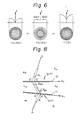
- Figure 8 shows a general theoretical principle of the grating lens assembly according to the present invention. For simplification, first, a one-dimensional construction will be analyzed below.
- the first grating lens (hologram lens) 11, which has a spatial frequency f1(x1, x2), and a second grating lens (hologram lens) 12, which has a spatial frequency f2(x1, x2), are located between a beam issuing point (light source) P and a beam converging point Q.
- the grating lenses 11 and 12 define three sections S1, S2, and S3.
- the abscissae x1 and x2 extend in the plane of the first and second grating lenses 11 and 12, respectively.
- optical paths PA , A Band BQ can be determined.
- the spatial frequencies f1(x1, x2) and f2(x1, x2) can be obtained by the following equations 2 and 3, which can be in turn obtained by differentiating the optical paths mentioned above,.
- ⁇ 1 and ⁇ 2A are the incident angle and diffraction angle of the first grating lens 11
- ⁇ 2B and ⁇ 3 are the incident angle and diffraction angle of the second grating lens 12.
- the sign of angle 6 is positive when viewed in a clockwise direction and the sign of the spatial frequency f is positive when it functions to diffract the beam in the counterclockwise direction.
- the point A' may be assumed to be represented by (x1 + Ax1). From this, From the equations 9 and 10, the following equation 11 can be obtained: By eliminating ⁇ from the equation 8 and 11,
- optical paths can be represented by the following equations 1' in place of the equation 1 .
- Figures 9 and 10 show another embodiment of the present invention, in which the incident beam of spherical wave from the point P in Fig. 1 is replaced with a coherent incident beam of a plane wave.
- the arrangement shown in Fig. 9 is quite the same as that of Fig. 3 except that the coherent incident light of a bundle of parallel rays of a plane wave is incident upon the first in-line grating lens 11.
- Figures 10 and 11 correspond to Figs. 1 and 4 of the aforementioned embodiment. Since the same discussion given for Figs. 1 and 4 are applicable to Figs 10 and 11, an explanation of Figs. 10 and 11 is omitted herein.
- the first grating lens 11 diffracts the incident light of a bundle of parallel rays, as mentioned above. Accordingly, it is meaningless to analyze the first grating lens by dividing it into two grating lens as shown in Fig. 4.
- Figure 12 shows examples of the spatial frequency of the grating lenses 11 and 12 shown in Fig. 9.
- the spatial frequency distributions F and f of the first and second grating lenses 11 and 12 present smooth curves which increase from the lens centers to the lens peripheries.
- the grating lens 12a of the second grating lens 12 which can be equivalently divided into two grating lenses, as explained before with reference to Fig. 4, has a spatial frequency distribution fa in which the spatial frequency is zero at the lens center and substantially linearly increases toward the lens periphery thereof.
- the spatial frequency distribution fb of the other grating lens 12b has a frequency band identical to the frequency band of the first grating lens 11 covering 430 to 620 mm - 1 and is such that the spatial frequency smoothly decreases from the lens center toward the lens periphery.
- the RMS values and the maxima of the wavefront aberration which are caused when the wavelength of the incident beam is changed from the center wavelength 830 nm by a variation ⁇ x were calculated.
- the results are shown in Fig. 13.
- the grating lenses 11 and 12 were designed so that they have the spatial frequency distributions in which no aberration takes place when the wavelengths are 830 nm and 830.3 nm, by the process shown in Fig. 10.
- Fig. 13 From the condition that when the RMS value is below 0.07 and the MAX value is below 0.25 ⁇ (RMS ⁇ 0.07 x, MAX ⁇ 0.25 x), it can be deemed that no aberration practically takes place, it can be found that no aberration can be maintained for the wavelength of 830 ⁇ 14 nm.
- the range of the wavelength of 830 ⁇ 14 nm can cover the wavelengths (including the fluctuation of the wavelength due to change of temperature) of the laser beam of almost all of the semiconductor lasers presently available on the market. It has been also confirmed in Fig. 13 that there was no deviation of the focal point.
- Figure 14 shows an example of a grating lens assembly which can be easily integrally constructed.
- the first and second grating lenses 11 and 12 are attached to opposite ends of a cylindrical housing 20, so that the grating lenses are coaxial to the optical axis.
- Figure 15 shows an example of an optical pickup which has the grating lens assembly 100 shown in Fig. 14.
- the grating lens assembly 100 is incorporated as an objective in an actuator 101 which is in turn connected to a rotary bobbin 103, so that the actuator 101 can move in the axial direction 107 and rotate in the direction 109 to perform focusing and tracking operations, as is well known.
- the pickup per se shown in Fig. 15 is a typical known pickup except for the objective, which is formed by a grating lens assembly embodying the present invention as mentioned above.
- the collimated beam L for example, from a semiconductor laser (not shown) is reflected upward by a mirror 105 to be incident upon the grating lens assembly 100, where the incident beam is converged upon a point, for example, on an optical disk (optical recording medium), not shown.
- the wavelength of the semiconductor laser beam L fluctuates, for example, due to change of temperature, the fluctuation does not substantially have an adverse influence on the beam spot converged upon the optical disk, because of the compensation effect by the grating lens assembly embodying the present invention.
- the pickup shown in Fig. 15 is lighter, smaller, and less expensive than conventional optical pickups, since a grating lens assembly embodying the present invention can realize a lighter, smaller, and inexpensive objective, in comparison with a conventional objective made of normal optical lenses.
- Figure 16 shows another grating lens assembly embodying the present invention.
- the first and second grating lenses 11 and 12 are formed on opposite sides of a transparent body 13 which has a thickness d and which can be made of, for example, a parallel glass plate.
- the embodiment shown in Fig. 16 is characterized by the provision of the transparent body 13 between the first and the second grating lenses 11 and 12, unlike the aforementioned embodiments in which the grating lenses are spaced from one another at a distance d.
- the grating lenses 11 and 12 are integrally secured to the parallel opposite side faces of the transparent body 13, there is no accidental relative displacement between the first and second grating lenses 11 and 12. Furthermore, according to the embodiment shown in Fig. 16, in which the transparent body 13 is provided between the grating lenses 11 and 12, it is possible to increase an average spatial frequency of the first and second grating lenses 1 and 12 in order to increase an efficiency of light without the need for blazing of the grating lenses, in comparison with the aforementioned embodiments in which the grating lenses are spaced. This leads to an increased of range of wavelength in which the fluctuation of the wavelength can be compensated.
- the grating lens assembly can be easily made integral with a semiconductor laser LD, since the grating lenses are integral with the transparent body 13 so as to be coaxial to the optical axis.
- Figures 17 and 18 show an example of a semiconductor laser beam converging module which has the grating lens assembly shown in Fig. 16 integral with a semiconductor laser LD.
- the transparent body 13 which is provided on its opposite side faces with the grating lenses 11 and 12 integral therewith, is fitted in a cylindrical housing 14 so as to abut against an inner annular flange 14a of the housing 14.
- the grating lens assembly having the transparent body 13 and the grating lenses 11 and 12 is secured to and in the cylindrical housing 14 by an annular screw 15 which is screwed in a threaded bore 14b of the housing 14.
- the semiconductor laser LD is provided on a mount 16 which has threaded bore 14b of the housing 14.
- the mount 16 also serves as a heatsink.
- the laser LD is attached to the center of the cylindrical annular mount 16, so that the axial position of the LD, namely the distance between the point P and the first grating lens 11 corresponding tp 1 in Fig. 1, can be easily adjusted by adjusting the axial screw movement of the mount 16.
- the module shown in Figs. 17 and 18 is, for example, practically 6 mm0 x 10 mm, which is very compact.
- Figure 19 shows an example of an application of a grating lens assembly embodying the present invention of an optical pickup.
- the illustrated pickup has a grating lens assembly having the transparent body 13 and the grating lenses 11 and 12 provided on the transparent body 13, a half mirror 17, an annular mirror 18, and a third grating lens 19.
- the half mirror 17 is provided between the first grating lens 11 and the transparent body 13 and has an optimum transmittance which is determined by taking the necessary intensity of light at the focal point Q and the amount of light to be returned to the laser LD into consideration.
- the mirror 18 is embedded in the transparent body 13 between the first and second grating lenses 11 and 12, so that a center opening 18a of the annular mirror 18 is located coaxial to the optical axis.
- the diffraction beam between the first and second grating lenses 11 and 12 passes through the center opening 18a of the annular mirror 18.
- the face of the mirror 18 that is located adjacent to the half mirror 17 is an annular mirror surface.
- the third grating lens 19 surrounds the first grating lens 11 and lies on the same plane of the first grating lens.
- the third grating lens 19 has a spatial frequency distribution which converges the beam in symmetry of revolution with respect to the optical axis.
- the laser beam from the LD is converged upon the focal point Q on the optical disk (recording medium) M through the first grating lens 11, the transparent body 13, and the second grating lens 12, as mentioned before.
- the beam reflected from the disk M at the point Q i.e., a signal beam
- the signal beam passes through the second grating lens 13 and through the center opening 18a of the mirror 18 and comes to the first grating lens 11.
- a part of the signal beam is reflected by the half mirror 17.
- the part of the signal beam which is reflected by the half mirror is diffused far from the optical axis, is reflected again by the annular mirror 18, and comes to the area outside the outer periphery of the first grating lens 11, in which area the third grating lens 19 is .provided, as mentioned above.
- the signal beam which reaches the third grating lens 19 is accordingly diffracted thereby in symmetry of revolution with respect of the optical axis, so that the signal beam diffracted by the third grating lens 19 is converged upon a focal point where a photdetector 21 is located.
- the photodetector 21, which is per se known, has an annular light receiving surface surrounding the LD so as to effectively receive the signal beam converged by the third grating lens 19.
- the signal beam from the optical disk M is brought to the photodetector 21 through the second and third grating lenses 12 and 19.
- the assembly of the second and third grating lenses 12 and 19 forms a grating lens assembly equivalent to the grating lens assembly having the first and second grating lenses 11 and 12, not sensitive to the fluctuation of the wavelength.
- the beam spot converged upon the photodetector 21 is substantially free from aberration and deviation of the focal point.
- the half mirror 17 can be formed by a known aluminum deposition processor or the like prior to the formation of the first grating lens 11 on the transparent body 13.
- the annular mirror 18 can be provided in the transparent body 13 in such a way that the transparent body 13 is made of two transparent bodies 13a and 13b which can be adhered to each other.
- a mirror surface is formed, for example, by A1-deposition, per se known, or the like on the side face of one transparent body 13a or 13b that is to be adhered to the other transparent body 13b or 13a, before the two transparent bodies 13a and 13b are adhered to each other, as shwon in Fig. 20.
- the adhesive which adheres the two transparent bodies 13a and 13b has a refractive index which is substantially identical to that of the transparent body 13 when it is cured or hardened.
- a refractive index which is substantially identical to that of the transparent body 13 when it is cured or hardened.
- an adhesive is a UV (ultraviolet radiation) curable adhesive.
- Figure 21 shows an example of an optical pickup which has the optical system shown in Fig. 19 incorporated therein, similar to the optical pickup shown in Fig. 15.
- components corresponding to those shown in Fig. 15 are designated with the same numerals. No additional explanation will be given here on these. Note that, in Fig. 21, the mirror 105 shown in Fig. 15 is removed since a spherical wave beam is incident upon the grating lens assembly in Fig. 21, unlike the arrangement shown in Fig. 15, in which a parallel plane wave beam is incident upon the grating lens assembly.
- Figure 22 shows a modification of Fig. 16.
- a parallel plane wave beam (coherent light) is incident upon the first grating lens 11, unlike the arrangement shown in Fig. 16, in which a spherical wave beam is incident upon the first grating lens 11.
- Figs. 16 and 22 corresponds to the relationship between Figs. 3 and 9 mentioned above.
- grating lens assemblies 11 and 12 it is also possible to provide more than one pair of grating lenses 11 and 12 in a one-dimensional or two-dimensional arrangement.
- One example of such multiple grating lens assemblies is shown in Figs. 23 and 24, in which a plurality of grating lens assemblies 100 are located in an array arrangement.
- Each grating lens assembly 100 corresponds to a module for example shown in Fig. 3, 9, 16, or 22.
- Fig. 79 shows a known rod lens array which has an array of a plurality of rod lenses 200
- Fig. 80 shows a known distributed index lens array in which a substrate 201 has spherical index distributions 203 therein to form a lens.
- the length of the rod lenses is about 8 mm, which is rather long, and that the rod lens array is very expensive.
- the distributed index lens array can be thinner than the rod lens array, it can only have a small numerical aperture (NA) of about 0.3 and aberration takes place due to the fluctuation of the wavelength.
- NA numerical aperture
- the grating lens array shown in Figs. 23 and 24 can have an increased density due to the face that the diameter of the lenses can be made smaller, resulting in an improved resolution.
- NA numerical aperture
- the grating lens array shown in Figs. 23 and 24 since there is only a small chromatic aberration (up to ⁇ 20 nm) due to the wavelength, not only the semiconductor laser but also an LED (light-emitting diode), which usually has a wavelength half-width of 20 to 40 nm, can be used as a light source.
- Figures 25 to 27 show an example of an application of the grating lens array mentioned above to a lens array for an LED array, which can be used, for example, in facsimiles or printers.
- the grating lens assemblies are located in a zigzag arrangement to form a grating lens array.
- the array has LED's which correspond to the grating lens assemblies.
- Each LED has, for example, a wavelength half-width of about 30 nm.
- the effective pitch q can be further decreased by increasing the number of lines of the grating lens assemblies.
- l 2 (the distance betwween the second grating lenses 12 and the surface R of a recording medium (e.g., electrostatic drum) on which the beam is to be focused)
- 1 2 200 ⁇ m in the case of a beam spot having a 2 to 3 ⁇ m diameter
- 1 z 2000 mm in the case of a beam spot having 20 to 30 ⁇ m diameter.
- the grating lens array shown in Figs. 25 to 27 can be made by shape duplication by using a plastic substrate. Namely, grating lens patterns of the first and second grating lenses 11 and 12 are printed in accordance with the dimensions as mentioned above, by electron beam writing and then Ni stampers are formed from resist patterns thus obtained by the grating patterns by a conventional method. Finally, the plastic substrate is subject to injection to duplicate the grating lens array.
- the lens array thus formed can have a large numerical aperture (NA) and accordingly an efficiency of collection of the LED beam can be increased and printing with high resolution can be effected due to a -decreased diameter of the beam spot.
- NA numerical aperture
- Figure 28 shows an optical pickup according to another aspect of the present invention.
- Japanese Unexamined Patent Publication (Kokai) No. 59-16061 discloses the arrangement shown in Fig. 81, in which the spherical wave beam (e.g., P-polarized light) issued from a semiconductor laser LD is diffracted by a holographic lens (which will be referred to as a hologram) 121, and the diffraction beam of parallel rays passes through a second hologram 122.
- a holographic lens which will be referred to as a hologram
- the hologram 122 functions to transmit, for example, a P-polarized light and diffracts an S-polarized light, so that the P-polarized light transmitted through the hologram 122 passes through a 1/4 x plate 125 and is then diffracted by a third hologram 123 to be converged upon the optical disk M.
- the signal beam reflected by the optical disk M passes through the third hologram and comes to the second polarizing hologram 122 through the 1/4 X plate 125.
- the P-polarized beam is converted to the S-polarized beam, so that the S-polarized beam is diffracted by the second hologram 122 toward a fourth hologram 124 which in turn converges the beam upon a photodetector 126.
- an optical pickup embodying the present invention as shown in Fig. 28 can be substantially free from such drawbacks.
- the first and second in-line grating lenses 11 and 12 are located on the optical axis between the semiconductor laser LD and the optical disk M.
- a polarization beam splitter 33 and a 1/4 X plate 31 are provided between the semiconductor laser LD and the first grating lenses 11 and between the second grating lens 12 and the optical disk M, respectively.
- the polarization beam splitter 33 which will be referred to as PBS hereinafter, transmits the P-polarized beam and reflects the S-polarized beam in this embodiment.
- the grating lenses 1 and 12 have the spatial frequency distributions as shown in Fig. 2.
- the laser beam (spherical wave) issued from the LD is transmitted through the PBS 33 and is incident upon the first grating lens 11.
- the beam incident upon the first grating lens 11 is diffracted in symmetry with respect to the optical axis and is then converged upon the optical disk M through the 1/4 plate 31 by the second grating lens 12.
- a stable beam spot having a constant diameter can be focused on a desired point of the disk M, by the grating lens assembly of the present invention.
- the signal beam which is designated by dotted lines and which is reflected by the disk M passes along the same optical path as the incident beam in the opposite direction and comes to the PBS 33. It is to be noted here that when the signal beam passes through the 1/4 X plate, the beam is converted to an S-polarized beam. The S-polarized signal beam is reflected by the PBS 33 and is then converged upon the photodetector 32. Since the signal beam passes through the grating lens assembly of the first and second grating lenses 11 and 12. according to the present invention, a stable beam having a constant small diameter can be focused on the photodetector 32.
- focusing error and tracking error can be detected by inserting a knife edge (not shown) between the PBS 33 and the photodetector 32 and behind the converging point of the signal beam.
- the photodetector 32 would be located behind the knife edge.
- Figure 29 shows an example of an actual construction of the optical pickup shown in Fig. 28.
- the incident laser beam issued from the LD passes through the PBS 33 and is diffracted in symmetry with respect to the optical axis by the first grating lens 11.
- the optical axis between the first grating lens 11 and the LD is parallel to the plane of the disk M.
- the diffracted beam by the first grating lens 11 is bent in a direction perpendicular to the optical axis of the first grating lens 11, i.e., perpendicular to the plane of the disk M by the mirror 35.
- the incident beam reflected and bent by the mirror 35 passes through the second grating lens 12 and the 1/4 plate 31 and is converged upon the disk M.
- the signal beam reflected by the disk M goes along the same optical path as that of the incident beam, but in the opposite direction, and is reflected by the PBS 33 to be converged upon the photodetector 32, which is located at a position different from the LD and at the same focal length of the first grating lens as the LD.
- the 1/4 X plate 31 can be placed between the first and second grating lenses 11 and 12 or between the PBS 33 and the first grating lens 11.
- Figure 30 shows a variant of Fig. 38, in which variant the optical grating lens system shown in Fig. 4 is incorporated.
- the first grating lens 11 is composed of two in-line grating lenses 11 a and 11
- the second grating lens 12 is composed of two in-line grating lenses 12a and 12b, respectively.
- the PBS 33 is located between the grating lenses 11a and 11b
- the 1/4 plate 31 is located between the grating lenses 12a and 12b.
- the optical function of the grating lens assembly having the first grating lens 11 which is divided into two grating lenses 11 a and 11 b and the second grating lenses 12 which is divided into two grating lenses 12a and 12bb is the same as that shown in Fig. 4.
- a fifth in-line grating lens 45 is provided between the PBS 33 and the photodetector 32.
- the fifth grating lens 45 converges the parallel rays of a signal beam which is split by the PBS 33 upon the photodetector 32.
- the fifth grating lens 45 has a spatial frequency distribution similar to the grating lenses 11 a and 11 a.
- the incident beam (spherical wave) which is issued from the LD is converted to parallel rays of a beam by the grating lens 11 a and is transmitted through the PBS 33 and comes to the grating lens 11 b.
- the parallel rays of the beam incident upon the grating lens 11 are diffracted to intersect with each other in symmetry with respect to the optical axis and are converted to parallel rays of the beam again by the grating lens 12b.
- the parallel beam passes through the 1/4 X plate 31 and is converged upon the focal point on the disk M by the grating lens 12a.
- the beam spot thus obtained is free from aberration and deviation of the focal point even under the fluctuation of the wavelength, as mentioned above.
- the signafbeam which is reflected by the disk M is returned to the PBS 33 in the direction opposite to the direction of the incident beam. Since the signal beam is converted to an S-polarized beam when it passes through the 1/4 X plate 31, the signal beam is reflected by the PBS 33 to be converged upon the photodetector 32 through the fifth grating lens 45. Since the signal beam passes through the grating lens assembly having the grating lenses 12a, 12b and 11b, 45, the fluctuation of the wavelength can be compensated for. It will be understood that for the signal beam reflected by the disk M, the fifth grating lens 45 corresponds to the grating lens 11 a.
- the first grating lens is formed by the grating lens 11 a and 11 b, for the incident beam issued from the LD and by the grating lens 11 b and the fifth grating lens 45, for the signal beam to be converged upon the disk M.
- the polarization splitting layer of the PBS 33 receives the parallel beam, so that the condition of the incident angle is identical anywhere in the polarization splitting layer, resulting in an increased polarization splitting efficiency. This results in an increased efficiency of the detection of the photodetector 32. The same is true in the 1/4 X plate 31.
- a mirror 40 is provided between the grating lens 11 and the grating lens 12b, so that the optical axis of the first grating lens 11 is perpendicular to the optical axis of the second grating lens 12, resulting in a thinner and more compact pickup, similar to the embodiment shown in Fig. 29.
- the mirror 40 is located between the grating lens 12b and the 1/4 ⁇ plate 31.
- the thickness of the pickup when viewed in the direction perpendicular to the plane of the disk M, i.e., in the direction of the optical axis of the second grating lens 12 can be further reduced in comparison with the embodiment illustrated in Fig. 31, since grating lens 12b is located on the optical axis of the first grating lens 11 in Fig. 32.
- the 1/4 plate 31 can be placed anywhere between the disk M and the PBS 33, and the PBS can be located between the LD and the grating lens 11 a instead of between the grating lens 11 a and 11b.
- the fifth grating lens 45 can be dispersed with.
- Figure 33 shows an optical pickup according to another embodiment of the present invention, in which the grating lens assembly having the first and the second grating lenses 11 and 12, as shown in Fig. 3 is generally designated by 50.
- a plate-like PBS 55 which has thereon a third grating lens 53 integral therewith is located between the LD and the grating lens assembly 50.
- the PBS 55 transmits only a linearly polarized light of a specific direction, for example, only an P-polarized light, (or S-polarized light) and reflects the S-polarized light (or P-polarized light).
- the first grating lens 11 has a 1/4 ⁇ plate 51 thereon. It is not always necessary to physically apply the 1/4 plate 51 to the first grating lens 11.
- the laser beam issued from the LD is reflected by the PBS 55 which is inclined with respect to the optical axis of the grating lens assembly 50 and is incident upon the first grating lens 11 of the grating lens assembly 50.
- the LD emits the P-polarized light in the direction perpendicular to the optical axis of the grating lens assembly 50 and the PBS 55 is inclined, for example, at 45° with respect to the optical axis of the grating lens assembly 50.
- the incident beam (e.g., P-polarized light) is converted to a circularly polarized light, so that the circularly polarized light is incident upon the first grating lens 11 of the grating lens assembly 50.
- the beam incident upon the grating lens assembly 50 is converged upon a predetermined point on the disk M without aberration even under the fluctuation of the wavelength and without deviation of the focal point, as mentioned before.
- the signal beam reflected by the disk M is returned to the PBS 55, as mentioned before.
- the signal beam passes through the 1/4 ⁇ plate 51, the signal beam is converted to a linearly polarized light. Namely the polarizing angle is changed by 90°. That is, the polarizing angle of the incident light upon the 1/4 X plate 51 is different by 90° from that of the signal beam transmitted through the 1/4 plate 51. Therefore the signal beam past the 1/4 X plate 51 is transmitted through the PBS 55.
- the plate-like PBS 55 is provided with the third grating lens 53 integral therewith, which serves as a half mirror, the signal beam is partly diffracted by the third grating lens 53 and is partly transmitted therethrough.
- One of the diffraction beam and the transmission beam for example, the diffraction beam B1
- the other beam i.e., the transmission beam B2
- the grating lens 53 can be easily given such a property of a half mirror by properly designing its grating (interference fringes).
- the focusing photodetector 57 and the tracking photodetector 59 are, for example, well known two-divided photodetectors, each having PIN photodiodes. Pits on the optical disk M, namely, the signals of channel-bits, can be detected by the photodetectors 57 and 59, outputs of which vary in accordance with the channel-bits.
- the focusing photodetector 57 is located slightly behind the focal point at which the signal beam is converged by the grating lens 53, so that two photodiodes 57a and 57b of the focusing photodetector 57 receive the identical amount of light when the optical disk M is exactly located at the distance of the focal length from the second grating lens 12.
- This exact focusing position is shown in Fig. 34(a). If the disk M is located far from the exact focal position shown in Fig. 34(a), the lower photodiode 57b receives a larger amount of the light than that of the upper photodiode 57a, as can be seen from Fig. 34(b).
- the output of the lower photodiode 57b is larger than that of the upper diode 57a.
- the optical disk M is located closer to the second grating lens 12 from the correct focal point, the amount of light which the upper photodiode 57a receives is larger than the amount of light which the lower photodiode 57b receives, as can be seen from Fig. 34(c).
- the focusing error detection method shown in Fig. 34 can be considered one kind of "knife edge method".
- the separation line which divides the two photodiodes 57a and 57b extends in a direction perpendicular to the interference fringes 53a of the third grating lens 53.
- the separation line of the photodiodes 57a and 57b extends in a direction the same as the direction of change of the diffraction direction of the beam by the third grating lens 53, that is, the direction perpendicular to the interference fringes 53a (Fig.
- the beam spot converged on the photodetector 57 moves only on the separation line and accordingly always comes onto the center line, i.e., the separation line, sepending on the change of the diffraction angle (direction) due to the fluctuation of the wavelength.
- Figure 36 shows the tracking photodetector 59.
- the tracking is effected by detecting the pits 5 of the disk M.
- the separation line of the two photodiodes 59a and 59b extends parallel to the tracks of the pits 5 of the disk M.
- the signal beam is converged upon the center of the separation line of the two photodiodes 59a and 59b, as shown in Fig. 36(a).
- the white portion of the beam spot on the photodiodes 59a and 59b actually appears as a dark portion.
- the dark portion of the beam spot on the photodetector 59 due to the deviation of the beam spot on the disk M appears on the photodiode that is located in the opposite side to the deviation of the beam spot on the disk M, as can be seen from Fig. 37.
- the tracking error detecting method utilizes a so-called “push-pull method” in which the difference in the amount of light between the two photodiodes is detected.
- Figure 38 shows an example of an actual construction of a pickup for an optical disk M according to the principle shown in Fig. 33.
- the first grating lens 11, the second grating lens 12, and the 1/4 X plate 51 are formed together in advance by a frame 63 and the secured to a housing 61.
- Numeral 40 designates a spacer which is located between the first grating lens 11 and the 1/4 plate 51. This is negligible from an optical viewpoint.
- the PBS 55 and the third grating lens 53 are integrally formed on the opposite sides of the glass plate 62, which is secured in place to the housing 61.
- the focusing photodetector 57 and the tracking photodetector 59 are directly housed in the wall of the housing 61.
- the semiconductor laser LD is also secured to the housing 61.
- the adjustment of the convergence of the incident beam upon the disk M can be easily effected by the positional adjustment of the LD and the adjustment of the convergence of the signal beam upon the photodetectors can be easily effected by the positional adjustment of the photodetectors 57 and 59.
- the tracking photodetector 59 which has two photodiodes 59a and 59b, is locaged close to the third grating lens 53, since the tracking photodetector 59 can detect the signal beam merely by detecting the difference in the amount of light between the two photodiodes 59a and 59b.
- This close arrangement of the tracking photodetector 59 contributes to a reduction of the thickness (width) W of the housing 61, resulting in a small pickup.
- the correction (adjustment) of the optical system in the pickup can be effected, for example by moving the entirely of the pickup, i.e., the housing 61, by a proper actuator, as shown in Fig. 15 or 21, with respect to the optical disk M.
- Figure 39 shows a variant of Fig. 33.
- the positional relationship of the photodetectors 57 and 59 is opposite to that of the photodetectors in Fig. 33. Namely, in Fig. 39, the transmission beam B2 of the third grating lens 53 is introduced to the focusing photodetector 57 and the diffraction beam B1 of the third grating lens 53 is introduced to the tracking photodetector 59.
- the tracking photodetector 59 has two photodiodes 59a and 59b, similar to Fig. 36.
- the tracking error can be detected by detecting a difference in the amount of light between the two photodiodes 59a and 59b in the push-pull method.
- the separation line- of the two photodiodes 59a and 59b extends parallel to the track of the optical disk M, so that when the beam spot converged upon the track of the disk M deviates upward and downward, as shown in Fig. 40, there is a difference in the amount of light between the photodiodes 59a and 59b, so that the tracking error can be detected.
- Figures 40(a), (b), and (c) show three positions in which the beam is correctly focused on the track (pit) of the disk M, the beam deviates downward, and the beam deviates upward, respectively.
- the separation line of the photodiodes 59a and 59b preferably extends in a direction perpendicular to the interference fringes 53a of the third grating lens 53 for the same purpose as that of Fig. 35.
- Fig. 41-(a), (b), and (c) correspond to the positions shown in Fig. 40(a), (b), and (c), respectively.
- the focusing photodetector 57 is a well known four-divided photodetector having four PIN photodiodes 57a, 57b, 57c, and 57d.
- the associated pits of the disk M can be detected by the sum (11 + 12 + l3 + 14) of outputs of the photodiodes, as is well known.
- the four photodiodes 57a, 57b, 57c, and 57d are geometrically arranged so that the focused beam spot can be located on the center of the four photodiodes, as shown in Fig. 42(a).
- the beam spot on the photodetector 57 deforms to an elliptical shape as shown in Fig. 42(b).
- the beam spot on the photodetector 57 deforms to an elliptical shape with a major axis extending perpendicular to the major axis or the ellipse shown in Fig. 42(b), as shown in Fig. 42(c).
- the focusing error can be detected. Namely, when the difference value is zero, the disk M is correctly located at the focal point of the grating lens assembly.
- the focusing can be performed by moving the housing 61 in a predetermined direction in accordance with the difference value by an actuator (not known) so as to make the difference value identical to zero. This is called the astigmatism method.
- the glass plate 62 which is provided on its opposite sides with the third grating lens 53 and the PBS 55 is an astigmatism element.
- Figure 43 shows an example of an actual construction of an optical pickup corresponding to Fig. 39:
- Fig. 43 The arrangement shown in Fig. 43 is the same as that of Fig. 38, except for the location of the focusing and tracking photodetectors 57 and 59. Namely, in Fig. 43, the tracking photodetector 59 and the focusing photodetector 57 are located at the positions of the focusing and tracking photodetectors 57 and 59 in Fig. 38, respectively. According to the embodiment illustrated in Fig. 43, the lateral width W' of the housing 61 can be decreased for the same reason as explained with respect to the width W in Fig. 38.
- the tracking and focusing photodetectors 59 and 57 are not limited to the two-divided or four-divided photodiodes as mentioned above and can be any photo detectors.
- the PBS 55 reflects the incident beam from the LD and transmits the signal beam in return from the disk in the aforementioned embodments, it is possible to use a PBS which transmits the incident beam from the LD and reflects the signal beam in return.
- Figures 44 to 55 show different embodiments which realize a two-beam type of optical pickup.
- Figure 82 shows a two-beam type of optical pickup disclosed in Japanese Patent Application No. 61-43702.
- hologram lenses grating lens
- laser beams 210 and 211 issued from two semiconductor lasers LD1 and LD2 are converged upon respective focal points Q1 and Q2 of the optical disk M by two hologram lenses 203 and 204 without aberration.
- the two points Q1 and Q2 are spaced at a predetermined distance do in the direction of track grooves of the disk M.
- the signal beams 212 and 213 reflected at the points Q1 and Q2 are converged upon respective photodetectors 205 and 206 by the opposite hologram lenses 204 and 203, respectively.
- the beam 210 from the LD1 is converged upon the point Q1 by the hologram lens 203.
- the signal beam 212 reflected at the point Q1 is converged by the other hologram lens 204 upon the photodetector 205.
- the beam 211 from the LD2 is converged upon the point Q2 by the second hologram 204 and the signal beam from the point Q2 is converged upon the second photodetector 206 by the first hologram lens 203.
- the signal beams (reflected beams) 212 and 213 are not returned to the LD1 and LD2, and come to the photodetectors 205 and 206 which are located adjacent to the respective LD2 and LD1.
- the optical paths of the two beams are spatially separated and accordingly neither a polarizing beam splitter nor 1/4 X plate are necessary.
- An embodiment of the present invention is also applicable to this kind of two-beam optical pickup to eliminate the problems of the occurrence of aberration and deviation of the focal point depending on the fluctuation of the wavelengths of the used laser beams.
- the first grating lens 11 is divided into two sections with respect to a plane including the optical axis, for each of the beams 210 and 211. This will be explained below in more detail with reference to Figs. 46 and 47.
- the first and second grating lenses 11 and 12 are divided into two first and second sections 11 At, 11 B1; 12A1, 12B1, having different diffraction angles, i.e., different spatial frequency distributions, respectively.
- first and second sections 12A1 and 12B1 of the second grating lens 12 are provided only for clarification and easy correspondence to the two sections 11A1 and 11 B1 of the first grating lens 11. Accordingly, they may have the same diffraction angle, i.e., the same spatial frequency distribution. In other words, it is not always necessary to divide the second grating lens 12 into two sections, as will be clarified hereinafter.
- the first and second sections 11A1 and 11B1 of the first grating lens 11 are in symmetrical arrangement with the second and first sections 12B1 and 12A1 of the second grating lens 12 when viewed in a plane perpendicular to the optical axis Xo-Xo.
- the beam incident upon the first section 12A1 of the second grating lens 12 is diffracted to be converged upon the point Q of the optical disk M by the first section 12A1 of the second grating lens 12.
- the spatial frequencies of the first and second grating lenses 11 and 12 are determined, so that the beam of the first LD1 follows the path mentioned above.
- the beam converged upon the point Q at a predetermined inclination angle with respect to the plane of the disk M is reflected at the point Q in the symmetrical direction with respect to the optical axis and comes to the second section 12B1 of the second grating lens 12.
- the signal beam from the point Q is then diffracted by the second section 11 B1 in a symmetrical direction with respect to the diffraction direction of the incident beam from the first LD1 mentioned above by the first section 11 B1 of the second grating lens 12 and comes to the second section 11 B1 of the first grating tens 11.
- the signal beam 212 incident upon the second section 11 B1 of the first grating lens 11 would be returned to the LD1, resulting in nondetection of the signal beam. This is the reason why the first section 11A1 and the second section 11B1 of the first grating lens 11 have different spatial frequency distributions. Because of the difference in spatial frequency between the first and second sections of the first grating lens, the signal beam 212 incident upon the second section 11 B1 of the first grating lens 11 can be converged upon a photodetector 205 located at a position different from LD1. The spatial frequency of the second section 11 B1 of the first grating lens 11 can be determined in accordance with the photodetector 205.
- the incident beam 210 and the signal beam 212 can be completely symmetrical with respect to the optical axis Xo-Xo in the second grating lens 12. Accordingly, it is unnecessary to divide the second grating lens 12 into the two sections 12A1 and 12B1, as mentioned before.
- the first section 12A1 through which the inward beam from the LD and to the point Q passes and the second section through which the outward beam (signal beam) from the point Q passes are named only for correspondence to the first and second sections of the first grating lens 11.
- the first grating lens 11 is divided into two sections 11A2 and 11B2, which have different spatial frequencies, with respect to a plane including the optical axis.
- the second grating lens 12 is also nominally divided into two sections 12A2 and 12B2.
- the signal beam 213 reflected at the point Q' of the disk M is diffracted by (the second section 12B2 of) the second grating lens 12 and is then diffracted by the second section 11 B2 of the first grating lens 11 to be converged upon a second photodetector 206 which is located at a position different from the LD2.
- the essential feature of a two-beam type optical pickup embodying the present invention is to provide separate paths for the inward and outward beams.
- the suffixes A and B correspond to the inward beam and the outward beam (signal beam), respectively.
- the suffixes 1 and 2 correspond to the first grating lens 11 and the second grating lens 12. Accordingly, for instance, 11 A designates the first section through which the inward beam 211 passes.
- Figures 44 and 45 show a basic construction of a two-beam optical pickup embodying the present invention, of which Fig. 44 corresponds to the first inward beams 210 and 211 issued from LD1 and LD2 and Fig. 45 corresponds to the outward beams (signal beams) 212 and 213 reflected from the points Q and Q' on the disk M.
- the first beam having the wavelength ⁇ 1 is used to write and erase the information in the recording disk M and the second beam having the wavelength ⁇ 2 is used to read (reproduce) the information to check whether or not the information is correctly written.
- the second beam is spaced behind at a predetermined slight distance do from the first beam in the direction of the tracks of the disk M. Either beam can be used for reading the information.
- the second converging point Q' of the second beam 211 is spaced from the first converging point Q of the first beam 210 at a distance do , which is usually 10 to 20 u.m.
- the center 0 (Fig. 49) of the separation line passing through the optical axis Xo-Xo between the first and second sections 11A1 and 11B1, for the first inward beam 210 ( ⁇ 1 ) is spaced at the distance do in the direction Z, from the center O' of the separation line passing through the optical axis X 0 '-X 0 ' between the first and second sections of the first grating lens 11, for the second inward beam 211 (x 2 ).
- This relation in a plan view is shown in Fig. 49.
- first and second sections 11A2 and 11 B2 of the first grating lens 11 for the second inward beam 211 are located in an arangement perpendicular to the arrangement of the first and second section 11 A1 and 11 B1 of the first grating lens 11 for the first inward beam 210, such a perpendicular arrangement is ⁇ not always necessary.
- the necessary condition is only the distance Do between the points 0 and 0' in the direction Z.
- first grating lens second grating lens
- the four sections 11A1, 11B1, 11A2, and 11B2 are formed with the arrangement shown in Fig. 49 on a substrate of the first grating lens (second grating lens).
- the spatial frequencies of the first sections 11A1 and 12A1 and the spatial frequencies of the second sections 1181 and 12B1 are such that the center wavelength thereof is, for example, 830 nm, and the spatial frequencies of the first sections 11A2 and 12A2 and the spatial frequencies of the second sections 11B2 and 12B2 are such that the center wavelength thereof is, for example, 780 nm.
- the spatial frequency of the first section 11A1 for the first beam 210 may be identical to the spatial frequency of the second section 11 A2 for the second beam 211, and the spatial frequency of the second section 11B1 for the first beam 210 may be identical to the spatial frequency of the second section 11B2 for the second beam 211.
- the first incident beam 210 ( ⁇ 1 ) issued from the first LD is incident upon the first section 11A1 of the first grating lens 11 at a predetermined incident angle and diffracted thereby in symmetry with respect to the optical axis in accordance with the spatial frequency of the first section 11A1 toward the first section 12A1 of the second grating lens 12.
- the beam 210 is then diffracted by the first section 12A1 of the second grating lens 12 in accordance with the spatial frequency thereof to be converged upon the first focal point Q on the disk M.
- the second incident beam 211 ( ⁇ 2 ) is converged upon the second focal pooint Q' on the disk M through the first section 11A2 of the first grating lens 11 and the first section 12A2 of the second grating lens 12.
- the first beam 210 which is converged upon the point Q at a predetermined inclination angle is reflected at the point Q to be the first signal beam 212.
- the first signal beam 212 follows a different path symmetrically opposed to the path of the inward beam 210 with respect to the optical axis and comes to the second section 12B1 of the second grating lens 12.
- the signal beam 212 is diffracted by the second section 12B1 in accordance with the spatial frequency thereof to come to the second section 11B1 of the first grating lens 11 and is then diffracted by the latter to be converged upon the first photodetector 205.
- the second incident beam 211 (h 2 ) from the second LD2 is reflected at the second focal point Q' on the disk M and the reflected beam (second signal beam) 213 is diffracted by the second section 12B2 of the second grating lens 12 and through the second section 11 B2 of the first grating lens 11 and is finally converged upon the second photodetector 206.
- Figure 50 shows a signal beam detection method of the second beam 211 of the LD2 (reproduction of information).
- the photodetector 206 consists of a focusing photodetector 57 and a tracking photodetector 59.
- the photodetectors 57 and 59 can be composed of PIN photodiodes as shown in Figs. 34, 36, and 42, mentioned before.
- the second signal beam 213 is split by a polarizing beam splitter (PBS) 77, which can be made of a hologram.
- the PBS hologram 77 can be located for example behind the second section 11 B2 of the first grating lens 11 when viewed in the direction of travel of the second signal beam.
- the PBS hologram 77 restricts the amount of the transmission beam therethrough depending on the diffraction angle. Namely, the PBS hologram 77 makes signals represented by the amount of light.
- the transmission beam of the PBS hologram 77 is divided into two beams by a half mirror 79. One of the divided signal beams is converged upon the focusing photodetector 57 and the other is converged upon the tracking photodetector 59.
- the tracking error detecting method shown in Fig. 51 A and the focusing error detecting method shown in Fig. 51 B are similar to those shown in Figs. 36 and 41, respectively.
- Figure 52 shows a different method of detection of the second signal beam (reproduction of information), in which the reflected beam of the half mirror 79 is used as a focusing error detecting beam and the transmission beam of the half mirror 79 is used as a tracking error detecting beam, unlike the arrangement shown in Fig. 50, in which the reflection beam of the half mirror is introduced to the tracking photodetector 59 and the transmission beam of the half mirror 79 is introduced to the focusing photodetector 57, respectively.
- the tracking error can be detected by a push-pull method as shown in Fig. 53A, similarly to Fig. 51 A.
- the tracking photodetector 57 can be made of two-divided photodiodes as mentioned above.
- the focusing can be effected, for example, by a knife edge method in which a knife edge 56 is used (Fig. 52), as shown in Fig. 53B.
- the knife edge method per se is well known.
- Figure 53B shows light distribution by the knife edge method, in which (a) shows an on-focus state 11 which the disk M is exactly located at the focal point of the seond grating lens 12, (b) shows that the disk M comes closer to the second grating lens 12, and (c) shows that the disk M goes farther from the second grating lens 12 respectively.
- the knife edge 56 is located on the Z axis.
- a two-divided PIN photodiode can be used which has a separation line extending parallel to the knife -edge.
- Figure 54 shows a detection method of the first signal beam at the erasure of information.
- the first signal beam 212 cause by the first incident beam 210 issued from the first LD1 is used.
- the first signal beam 212 diffracted by the second section 1161 of the first grating lens 1 can be directly introduced to the tracking photodetector 57', which corresponds to the photodetector 205 shown in Fig. 45.
- the photodetector 57' is comprised of a two-divided PIN photodiode similar to the photodiode shown in Figs. 52 and 53A.
- Figure 55 shows an example of an actual construction of the two-beam type optical pickup mentioned above.
- the first grating lens 11 and the second grating lens 12 are located so that the optical axes thereof are normal to each other and a mirror 151 is provided between the first and second grating lenses 11 and 12. Namely, the beams issued from the first grating lens 11 are bent by 90° by the mirror 151 toward the second grating lens 12 and vice versa.
- the arrangement in which the first grating lens 11 and the second grating lens 12 are perpendicular to each other contributes to a reduction of the thickness of the pickup in the direction perpendicular to the plane of the disk M, similar to the embodiments shown in Figs. 29, 31, 32 etc.
- "T" in Fig. 55 shows a track of the disk M.
- Figure 56 shows an optical pickup according to another embodiment of the present invention, in which the improvement is directed to effective utilization of the space between the two grating lenses 11 and 12, which must be spaced at the distance d from each other, as mentioned above.
- the optical elements such as photodetectors and half mirrors, etc. are all located in a space defined by and between the grating lenses 11 and 12.
- a third hologram 131 is provided between the first grating lens 11 and the second grating lens 12 to split outward the signal beam reflected at the point Q on the disk M into two beams.
- the hologram 131 functions as a half-mirror or polarizing beam splitter (PBS).
- the beam issued from the point P is converged upon the focal point Q on the disk M by the first and second the grating lenses 11 and 12, as mentioned before.
- a part of the incident beam is transmitted through the hologram 131 and is then diffracted by the second grating lens 12 to be converged upon the point Q on the disk M, as mentioned above.
- the signal beam reflected at the point Q is returned to the point P along the same path as the inward path in the opposite direction.
- the signal beam is partly transmitted through and partly diffracted by the hologram 131.
- the diffraction angle of the hologram 131 is designed so that the diffraction beams are directed outward with respect to the optical axis.
- the first order diffraction beams are reflected by mirrors 141 and 142 which are located on the same plane of the first grating lens 11.
- photodetectors 143 and 144 which are made of, for example, PIN photodiodes, similar to the aforementioned embodiments.
- the hologram 131 has at least two hologram sections having different spatial frequency distributions. Note that "between the first and second grating lenses" referred to herein includes a space defined by the extensions of the planes of the first and second grating lenses 11 and 12.
- Figure 57 shows the appearance of the pickup shown in Fig. 56.
- the optical principle of the pickup shown in Fig. 57 is quite the same as that shown in Fig. 1.
- numeral 151 designates a transparent body, such as a glass plate, which has on its opposite sides the first and the second grating lenses 11 and 12 and which has on its other opposite sides the photodetectors 143 and 144.
- Figure 58 shows an actual construction of an optical pickup which has the grating lens system illustrated in Fig. 56 incorporated therein.
- the transparent body (first substrate) 151 has on its one side face reflecting layers M1 and M2, which form the reflecting mirrors 141 and 142, and on its opposite side face a recording medium 153 which forms the hologram 131.
- the transparent body 151 can be made of, for example, polished BK 7 which is a glass material with parallel side faces.
- the reflecting mirror layers M1 and M2 can be made of, for example, vapor-deposited aluminum.
- the hologram recording medium 153 is preferably a material of which a volume hologram is made, such as photopolymer, since a 1/4 plate 157 is directly secured thereto, as will be explained hereinafter.
- the first grating lens 11 can be formed on a second transparent body 161 (e.g., BK 7) similar to the first transparent body 151 by electron beam writing or holographic process or another known process.
- the second transparent body (second substrate) 161 can be directly secured to the reflecting layers (surfaces) M1 and M2 of the first transparent substrate 151 by means of an adhesive 163 or the like.
- To the side face of the first substrate 151 on which the recording medium 153 is formed is secured a third transparent substrate 157 which is the form of a 1/4 plate in the illustrated embodiment and which has the second grating lens 12 integral therewith on one side face of the third substrate, by means of an adhesive 164 or the like.
- the second grating lens 12 can be formed on the third substrate 157 by a similar process to that of the first grating lens 11.
- the 1/4 plate 157 has good parallel side faces.
- the signal beam splitting hologram 131 amy be merely a beam splitter but preferably is a polarizing beam splitter (PBS).
- PBS polarizing beam splitter
- Such a hologram 131 can be made, for example, by copying a master hologram which is in turn made, for example, by electron beam writing, an interference exposure process, or the like in a coherent copying process.
- the three substrates 151, 157 and 161 are secured together by means of the adhesives 163 and 164, such as U.V curable adhesives, after they are aligned on the optical axis (Fig. 59).
- the photodetectors 143 and 144 are secured to the opposite end faces of the first substrate 151.
- the assembly 70 (Fig. 59) thus obtained is secured to one end face of a hollow tubular housing 171, as can be seen in Fig. 58.
- a heat sink 175 which has laser beam source, such as a semiconductor laser 173 (LD).
- LD semiconductor laser 173
- the LD 173 is aligned on the optical axis and is spaced at a predetermined distance from the assembly 70.
- the positional adjustment of the LD 173 can be effected while observing the beam spot on the point Q of the disk M converged by the second grating lens 12.
- the positional adjustment of the photodetectors 143 and 144 can be effected by statically creating the signal beam (reflection beam) while observing an error signal.
- the housing 171 is connected to an actuator, as shown in Fig. 15 or 21, so that the entirety of the optical system can be moved in predetermined directions including rotation, similar to the actuation of a conventional objective.
- Figure 60 shows a function of the PBS hologram 131 shows in Fig. 58.
- the hologram 131 is divided into two sections 131a a and 131b having different holograms.
- the hologram sections 131 a and 131 b diffract the beam outward far from the optical axis in the opposite directions and converge the beam upon predetermined points, respectively.
- the rays of the signal beam travelling toward the first grating lens 11 from the second grating lens 12 form a conical generatrix on the circular band above the second grating lens 12.
- the hologram 131 is divided into two sections 131a and 131b by a separation line including the center thereof, as mentioned above.
- the respective hologram sections 131 a and 131 b diffract the beams outward far from the optical axis toward the respective mirrors (reflecting layers) M1 and M2, so that the beams are converged upon the respective photodetectors 143 and 144.
- NA 5 1/10 the focal length of the convergency beam
- the PBS hologram 131 transmits only a linearly polarized beam having a specific directions and diffracts the linearly polarized beam having a direction perpendicular thereto, as is well known. For instance, in the illustrated embodiment, the PBS hologram 131 transmits only the P-polarized beam and diffracts the S-polarized beam.
- the interference fringes of the hologram 131 substantially extend in the direction of the separation line 130 (Fig. 61) of the two sections 131 a and 131 b of the hologram 131.
- the beam which is incident upon the hologram 131 is an S-polarized beam over almost all the hologram area, so that the signal beam can be effectively split, as will be explained hereinafter.
- the beam of spherical wave (which is supposed to have a polarization in a direction designated by an arrow A in Fig. 58) issued from the LD 173 is diffracted by the first grating lens 11 to intersect on the optical axis, as mentioned above. Since the PBS hologram 131 has interference fringes substantially perpendicular to the sheet of the drawing in Fig. 58, the semiconductor laser beam incident upon the hologram 131 is almost a P-polarized beam. As a result, the holgram 131 transmits the laser beam (P-polarized beam), so that the transmission beam comes to the 1/4 X plate 157.
- the linearly polarized beam incident upon the 1/4 X plate is converted to the circularly polarized beam thereby and reaches the second grating lens 12.
- the second grating lens 12 converges the beam upon the focal point Q on the disk M to create a small beam spot.
- the flucturation of the wavelength of the laser beam can be effectively absorbed by the grating lens assembly embodying the present invention.
- the signal beam which is reflected at the point Q travels on the same path as that of the inward beam from the point P to the point Q until the signal beam reaches the 1/4 plate 157.
- the signal beam passes through the 1/4 ⁇ plate 157, it is converted to the linearly polarized beam which has a polarization angle different by 90° from that of the linearly polarized inward beam.
- the outward beam (signal beam) which has passed the 1/4 plate 157 is an S-polarized beam.
- the S-polarized beam is diffracted and split by the two sections 131 a and 131 b of the PBS hologram 131.
- the split signal beams are reflected by the mirrors M1 and M2 which are located on the same plane as the first grating lens 11 to be converged upon the photodetectors 143 and 144.
- Figure 61 shows the detection method of the photodetectors 143 and 144 shown in Fig. 58.
- the focusing error and the tracking error can be detected by the outputs of the photodetectors 143 and 144, as mentioned before.
- the photodetectors 143 and 144 are both two-divided PIN photodiodes in the illustrated embodiment.
- the focusing can be performed, for example, by a method equivalent to the knife edge method, and the tracking can be performed, for example, by a push-pull method, mentioned before.
- the focusing error can be detected by ⁇ (a - b) + (d - c) ⁇ and the tracking error can be detected by ⁇ ( a + b ) - (c + d) ⁇ .
- Figure 62 shows a variant of the PBS hologram 131, in which the hologram 131 is divided into three sections 131a, 131b, and 131c having different holograms.
- the photodetector 144 is a three- divided PIN photodiode, outputs of which are designated by c, d, and e in Fig. 62.
- the focusing error and the tracking error can be detected similarly to the embodiment shown in Fig. 61. It should be appreciated that in the embodiment shown in Fig. 62, the focusing error and the tracking error can be independently detected. Namely, the focusing can be effected by the photodetector 144 and the tracking by the photodetector 143.
- the tracking error is detected by the difference (a - b) in output between the two photodiodes of the photodetector 143 and the focusing error is detected by the difference ((d - (c + e) ⁇ in output between the three photodiodes of the photodetector 144.
- the track direction corresponds to the direction Y.
- Figures 63 and 64 show an embodiment in which a grating lens assembly embodying the present invention is applied to a focusing device.
- Figs. 63 and 64 the rays of the laser beam (wavelength ⁇ 0 ) issued from the LD (point P) are diffracted in symmetry of revolution to intersect the optical axis and reach the second grating lens 12. The beam is then diffracted by the second grating lens 12 to be converged upon a predetermined point Q in accordance with the spatial frequency thereof, as mentioned before with reference to Figs. 1 and 2.
- the laser beam source LD there can be used a tunable laser, per se known, which can vary the wavelength of the emitting beam.
- Figure 64 shows how to determine the spatial frequencies of the first and second grating lenses 11 and .12.
- the spatial frequencies of the grating lenses 11 and 12 can be determined by similar processes as mentioned before with reference to Fig. 1.
- Fig. 64 supposing a beam a of a wavelength ⁇ 0 which is issued from the point P and which reaches the outermost peripheral point R1 of the first grating lens 11 which is spaced from the point P at a distance l 1 , the beam a is diffracted at the point R1 toward the center point r1 of the second grating lens 12. Then, the beama is diffracted by the second grating lens 12 to be converged upon the point Q.
- the spatial frequencies F1 and f1 at the points R1 and r1 are determined by supposing the path of R - R1 - r1 - Q.
- the beam which travels from the point P to the point R1 is diffracted at the point R1 in a different direction with a different diffraction angle from the wavelength ⁇ 0 , so that the beam comes to the point r2 of the second grating lens 12, different from the point r1 (beam b).
- the spatial frequency f2 at the point r2 can be determined.
- a beam c of a wavelength x o which is diffracted at the point r2 to be converged upon the point Q is taken into consideration again to determine a position R2 of the first grating lens 11 from which the beam c is emitted.
- a spatial frequency F2 at the point R2 can be determined.
- a third point r3 (not shown of the second grating lens 12 which the beam reaches and a spatial frequency F3 can be determined.
- a third point R3 (not shown) on the first grating lens 11 and a spatial frequency F3 thereat can be determined, similarly to the above.
- the radius of the second grating lens 12 can be determined in accordance with the value of rn, corresponding to the point Rn of the first grating lens 11.
- Fig. 64 shows a crosssection including the optical axis and that the lenses themselves are symmetrical with respect to the optical axis.
- Figure 65 shows an example of radial spatial frequency distributions of the grating lenses 11 and 12 determined by the above-mentioned processes.
- grating lenses 11 and 12 shown in Figs. 4, 5 and 6 are applicable to the embodiment shown in Figs. 64 and 64.
- Figure 66 shows the relationship between the variation ⁇ x (nm) of wavelength and the displacement ⁇ l 2 ( ⁇ m) of the focus, in an embodiment shown in Fig. 63.
- the moved focus must be without aberration.
- calculations were made to obtain the RMS value of wavefront aberration which was caused when the wavelength of the laser beam was changed from 830 nm, for each of "T1", “T2", and “T3", shown in Fig. 66. The results are shown in Fig. 67.
- the spatial frequency distributions of the grating lenses 11 and 12 were designed so that the center wavelengths at which no aberration takes place were 830 nm and 830.3 nm, respectively.
- the focus can be moved without aberration by varying the wavelength. It should be appreciated that no mechanical drive is necessary for controlling the focus, since the control can be effected only by varying the wavelength of the emitting beam.
- the control of the focus becomes simpler, since the tunable laser can vary the wavelength of the laser beam emitted therefrom.
- Figure 83 shows a known focus controlling servo system, in which the wavelength of the beam emitted from a semiconductor laser LD is controlled by a wavelength control unit in accordance with an focus error of the convergence beam, to move the focus from the point Qo to Q 1 or 0 2 , as disclosed in Japanses Unexamined Patent Publication (Kokai) No. 60-66337.
- this known system Aberration occurs when the wavelength of the beam is varied, resulting in difficulty in accurately reading the signal beam.
- Figure 68 shows an application of the focusing apparatus shown in Figs. 63 and 64 to a beam scanning apparatus.
- a polygonal mirror 411 rotates about a shaft 313 to scan the beam 310 which is issued from the semiconductor laser LD and which is converted to a converging beam with long focal length by a lens 315.
- the scanning beam 310 is imaged on and along a circular track K which is a part of a circle having a center on the associated reflecting surface of the polygonal mirror 311. Accordingly, for example, when the scanning system is used for laser printer in which the scanning beam must be scanned along and on a straight surface of a recording drum 317, no exact small beam spot can be converged on the drum.
- f-e lens 319 which enables the scanning beam 310 to be imaged on the straight surface of the drum.
- f-e lens 319 is very expensive and requires high skill for manufacture.
- the scanning beam 310 can be exactly focused on and along the straight line of the drum 317 by using the focusing apparatus shown in Figs. 63 and 64.
- the wavelength of the laser beam issued from the LD is controlled, for example, by a curve shown in Fig. 69.
- the abscissa designates the time t and the ordinate designates the wavelengths x.
- x A , ⁇ B , and ⁇ C are wavelengths at the points A, B, and C on the straight line of the drum 317 shown in Fig. 68.
- a grating lens assembly 100 having the first and the second grating lenses 11 and 12 shown in Fig. 63, so that when the wavelength of the laser beam varies, no aberration occurs, as mentioned before.
- Figure 70 shows the general relationship betwen the angular displacement 6 (abscissa) of the polygon mirror 311 and the variation of the focus (focal length ⁇ f. "A" in Fig. 70 corresponds to the point A in Fig. 68.
- Figure 71 shows the general relationship between the variation ⁇ f (abscissa) of wavelength and the variation ⁇ x (ordinate) of a focus, from which it can be seen that there is a linear relationship between ⁇ and Af. From Figs. 70 and 71, the relationship between the angular displacement 6 of the polygon mirror 331 and the variation ⁇ x of the wavelength can be obtained, as shown in Fig. 72. In Fig. 72, "A" corresponds to the center point A in Fig. 68.
- the beam can be constantly focused on a predetermined pattern (e.g., straight line) by controlling the wavelength of the beam, thereby to control the focus, without using a mechanical drive or actuator for varying the focus.
- a predetermined pattern e.g., straight line
- a grating lens assembly having first and second grating lenses with predetermined spatial frequency distribution is not sensitive to fluctuation of the wavelength of the used beam. Accordingly, no aberration and no deviation of the focal point occur even if the wavelength varies.
- an embodiment of the present invention can provide an optical system for focussing near mono-chromatic light from a source at.a first point (P), on an optical axis of the system, onto a second point (Q) spaced therefrom on the said optical axis, the system comprising first and second grating lenses (11, 12) located between the said first and second points (P, Q) and spaced apart along the said optical axis, and the respective grating patterns and positioning of the two grating lenses (11, 12) being selected so that all rays of the near mono-chromatic light that are within a predetermined range of wavelengths and that pass through the two grating lenses (11, 12) will be directed to reinforce one another (constructive interference) at the said second point (Q) by first order diffraction through the two grating lenses (11, 12).
Abstract
Description
- The present invention relates to an optical system with a grating lens assembly which converges rays of light.
- Grating lenses are used in optical systems such as optical heads of optical disk apparatuses, in which a divergent bundle of rays of spherical waves from a coherent light source is converged upon a point, to realize compact, light, and inexpensive optical systems with reduced access times. Grating lenses are usually thinner, lighter, and more suited for mass production than conventional optical elements.
- A grating lens functions to converge a bundle of parallel rays of only a specific wavelength upon a point. Accordingly, if the wavelength changes, the grating lens no longer converges the bundle of rays. Namely, use of a grating lens has the drawback that if the wavelength deviates from a predetermined value, an aberration occurs and/or a deviation of the focal point takes place.
- A semiconductor laser is usually used as a coherent light source in an optical head of an optical disk apparatus. The wavelength of the semiconductor laser usually fluctuates in accordance with changes in the ambient temperature, which is usually not constant, and with changes in a driving current of the laser. -
- Accordingly, it is desirable to provide an optical system with a grating lens assembly which substantially absorbs any deviation of the wavelength of the incident light so as to create a good beam spot on a focal point substantially without aberration.
- It is also desirable to provide a reliable and precise optical pickup having such a grating lens assembly which is substantially free from aberration even if the wavelength of the incident light changes.
- Further, it is, desirable to provide a reliable and precise focusing device having such a grating lens assembly which is substantially free from aberration even if the wavelength of the incident light changes.
- According to one aspect of the present invention there is provided an optical system having a grating lens assembly comprising a first grating lens, which diffracts rays of an incident beam so as to provide non-parallel diffraction rays, and a second grating lens, which converges the non-parallel diffraction rays with a predetermined pattern substantially without aberration.
- According to another aspect of the present invention, such an optical system, having the grating lens assembly mentioned above, may be applied to an optical pickup which can be used, for example, in an optical disk apparatus to provide a good beam spot without an aberration or deviation of the focal point.
- According to a further aspect of the present invention, there is provided a focusing apparatus in which the focus can be controlled by using an optical system having a grating lens assembly as mentioned above. The focus can be varied by changing the wavelength of the incident beam.
- According to yet another aspect of the present invention, the focusing apparatus is applied to a beam scanning apparatus, in which a beam can be focused on and along a predetermined pattern.
- Reference will now be made, by way of example, to the accompanying drawings, in which:
- Fig. 1 is a schematic view of a grating lens assembly, showing how to determine spatial frequencies of grating lenses used in embodiments of the present invention;
- Fig. 2 is a diagram showing an example of distribution of spatial frequencies of grating lenses shown in Fig. 1;
- Fig. 3 is a schematic view of a grating lens assembly embodying one aspect of the present invention;
- Fig. 4 is a schematic view of a grating lens assembly, for explaining distribution characteristics of spatial frequencies of grating lenses shown in Fig. 1;
- Fig. 5 is a diagram of an example of spatial frequencies of grating lenses shown in Fig. 4;
- Fig. 6 is a view showing interference fringes of grating lenses according to the distribution of spatial frequencies shown in Fig. 5;
- Fig. 7 is a diagram showing a relationship between an RMS wavefront aberration and a wavelength of a semiconductor laser, by way of an example, in an embodimenf of the present invention;
- Fig. 8 is a schematic view showing a principle of a grating lens assembly embodying the present invention;
- Fig. 9 is a view similar to Fig. 3, but showing another embodiment of a grating lens assembly;
- Fig. 10 is a view similar to Fig. 1, showing how to determine spatial frequencies of grating lenses shown in Fig. 9;
- Fig. 11 is a view similar to Fig. 4, for grating lenses shown in Fig. 10;
- Fig. 12 is a diagram showing an example of a distribution of spatial frequencies of grating lenses shown in Fig. 11;
- Fig. 13 is a diagram showing a relationship between an RMS wavefront aberration and a deviation of wavelength;
- Fig. 14 is a partly sectional view of a construction of a grating lens assembly embodying the present invention;
- Fig. 15 is a perspective view of an optical pickup having a grating lens assembly shown in Fig. 14 incorporated therein;
- Fig. 16 is a schematic view of another grating lens assembly embodying the present invention;
- Fig. 17 is a sectional view of a module for converging the semiconductor laser using a grating lens assembly shown in Fig. 16;
- Fig. 18 is a perspective view of a module shown in Fig. 17;
- Fig. 19 is a schematic view of an optical pickup embodying another aspect of the present invention;
- Fig. 20 is an explanatory view showing how to embed a mirror in a transparent body shown in Fig. 19;
- Fig. 21 is a perspective view of an optical pickup having a grating lens assembly shown in Fig. 19;
- Fig. 22 is a schematic view of a further grating lens assembly embodying the present invention;
- Fig. 23 is a plan view of an array of grating lenses using a grating lens assembly shown in Fig. 16;
- Fig. 24 is a sectional view taken along the line XXIV-XXIV in Fig. 23;
- Fig. 25 is a plan view of a lens array for an LED array using a grating lens assembly shown in fig. 16;
- Fig. 26 is a sectional view taken along the line XXVI-XXVI in Fig. 25;
- Fig. 27 is a sectional view taken along the line XXVII-XXVII in Fig. 25;
- Fig. 28 is a schematic view of an optical pickup embodying an aspect of the present invention;
- Fig. 29 is.a perspective view of another optical pickup embodying an aspect of the present invention;
- Fig. 30 is a schematic view of a further optical pickup embodying an aspect of the present invention;
- Fig. 31 is a perspective view of an optical pickup embodying an aspect of the present invention;
- Fig. 32 is a perspective view of an optical pickup embodying an aspect of the present invention;
- Fig. 33 is a schematic view of an optical pickup embodying an aspect of the present invention;
- Fig. 34 is a schematic view showing how to detect focusing beams in a pick-up shown in Fig. 33;
- Fig. 35 is a schematic view showing that a change of wavelength of incident light does not have any adverse influence on a focusing detector in a pick-up shown in Fig. 33;
- Fig. 36 is a schematic view showing the detection of a tracking beam in a pickup shown in Fig. 33;
- Fig. 37 is an explanatory view showing the "inversion" of a dark portion of the light;
- Fig. 38 is a partially sectioned view of an actual construction of an optical pickup shown in Fig. 33;
- Fig. 39 is a schematic view of another optical pickup embodying an aspect of the present invention;
- Fig. 40 is a view showing the detection of a tracking beam, in a pickup shown in Fig. 39;
- Fig. 41 is an explanatory view showing that a change in the wavelength does not have any adverse influence on the tracking detector;
- Fig. 42 is a view showing the detection of a focusing beam in a pickup shown in Fig. 39;
- Fig. 43 is a partial sectional view of an actual construction of an optical pickup shown in Fig. 39;
- Fig. 44 is a schematic view of a two-beam type of optical pickup, in which an incident beam is converged, embodying the present invention;
- Fig. 45 is a schematic view of a two-beam type of optical pickup, in which a signal beam is converged, embodying the present invention;
- Fig. 46 is a schematic view showing a principle of a two-beam type of optical pickup shown in Figs. 44 and 45;
- Fig. 47 is a schematic view showing a principal arrangement of a first beam in a two-beam type of optical pickup shown in Figs 44 and 45;
- Fig. 48 is a view similar to Fig. 47 for a second beam in a two-beam type of optical pickup;
- Fig. 49 is a plan view showing a geometrical arrangement of two divisional areas in a two-beam type of optical pickup;
- Fig. 50 is a view showing how to detect a signal beam when information is read out;
- Fig. 51 A is a view showing a tracking method in a two-beam type of optical pickup;
- Fig. 51 B is a view showing a focusing method in a two-beam type of optical pickup;
- Fig. 52 is a view showing a variant of Fig. 50;
- Fig. 53A is a view showing a tracking method in an arrangement shown in Fig. 52;
- Fig. 53B is a view showing a focusing method in an arrangement shown in Fig. 52;
- Fig. 54 is a view showing the detection of a signal beam when information is written and erased;
- Fig. 55 is a perspective view of an actual arrangement of a two-beam type of optical pickup;
- Fig. 56 is a schematic view of an optical pickup according to a modified embodiment of the invention;
- Fig. 57 is a view showing an outer appearance of an optical pickup shown in Fig. 56;
- Fig. 58 is a partial sectional view of an optical head having an optical pickup shown in Fig. 57;
- Fig. 59 is an exploded view of optical components of an optical head shown in Fig. 58;
- Fig. 60 is a view showing a function of a hologram for splitting a signal beam in an optical head shown in Fig. 58;
- Fig. 61 is a view showing the detection of focusing and tracking beams in an optical head shown in Fig. 58;
- Fig. 62 is a view showing another method of detection of focusing and tracking beams in an optical head shown in Fig. 58;
- Fig. 63 is a view of a grating lens assembly used in a focusing device embodying the present invention;
- Fig. 64 is a view showing how to determine spatial frequencies of grating lenses used in a grating lens assembly shown in Fig. 63;
- Fig. 65 is a diagram showing a distribution of spatial frequencies of grating lenses shown in Fig. 64;
- Fig. 66 is a diagram showing a relationship between a change in wavelength and displacement of a focal point in a focusing device shown in Fig. 64;
- Fig. 67 is a diagram showing a relationship between an RMS wavefront aberration and a change of wavelength in a focusing device shown in Fig. 64;
- Fig. 68 is a perspective view of an optical scanning device embodying the present invention;
- Fig. 69 is a diagram showing a relationship between wavelength and time in an optical scanning device shown in Fig. 68;
- Fig. 70 is a diagram showing a relationship between angular displacement of a polygonal mirror and change in a focal length in an arrangement shown in Fig. 68;
- Fig. 70 is a diagram showing a relationship between change of wavelength and change of focal length in a scanning device shown in Fig. 68;
- Fig. 72 is a diagram showing a diagram of a relationship between change of wavelength and angular displacement of a polygonal mirror in a scanning device shown in Fig. 68;
- Fig. 73 is a view showing an aberration in an in-line type of grating lens according to the prior art;
- Figs 74A, 74B, and 74C are views showing various known hologram lenses;
- Fig. 75 is a view showing an aberration and deviation of a focal point in an off-axis type of grating lens according to the prior art;
- Figs. 76A and 76B are diagrams showing light intensities of a single-mode semiconductor laser and a multimode semiconductor laser, respectively;
- Fig. 77 is a diagram showing variation of wavelength depending on temperature in a single mode semiconductor laser;
- Fig. 78 is a view showing a known grating lens optical system;
- Fig. 79 is a perspective view of a known rod lens array;
- Fig. 80 is an explanatory perspective view of a known distributed index lens array;
- Fig. 81 is a view of a known optical pickup;
- Fig. 82 is a view of a known two-beam type of optical hologram pickup;
- Fig. 83 is a view of a known focus-servo system;
- Fig. 84 is a perspective view of a known beam scanning device; and
- Fig. 85 is a view similar to Fig. 84 but showing another known beam scanning device.
- First referring to Figs. 73 to 77, which show the prior art, a conventional grating lens G shown in Fig. 73 converges a bundle of parallel rays of only a specific wavelength λ0 upon a focal point Q. Accordingly, the grating lens G does not converge the bundle of parallel rays of a different wavelength X (X > >.0 in Fig. 73) upon the focal point Q. Namely, aberration occurs as shown at A in Fig. 73. This results in a bad conversion efficiency. The same is true when the wavelenth of the incident light changes to a smaller value (a < 0λ0).
- This kind of phenomenon occurs commonly with a lens which diffracts rays of light. Namely, the aberration takes place when the wavelength of the incident light changes, for exampole in a volume hologram lens as shown in Fig. 74A, a surface relief hologram as shown in Fig. 74B, and a blazed grating lens as shown in Fig. 74C.
- Figure 75 shows the occurrence of aberration in an off-axis type of grating lens G. In the case of an off-axis type of grating lens, deviation of the focal point from the optical axis Xo-Xo occurs in addition to the aberration, as can be seen from Fig. 75.
- As can be understood from the foregoing and as is well known a grating lens causes an aberration when the wavelength of the light incident thereupon deviates from a predetermined value (Xo), resulting in a bad conversion of a bundle of rays. In addition, deviation of the focal point from an optical axis takes place in certain kinds of lenses.
- For instance, in an optical head in an optical disk apparatus, a semiconductor laser is usually used as a coherent light source. There are two types of semiconductor laser: a single mode laser and a multimode laser. Figures 76A and 76B show states of the wavelenths of the respective lasers.
- In conventional common optical heads in which normal optical lenses are used, there is substantially no change in a beam spot on a focal point even if the wavelength of the incident light upon the optical lenses changes. Accordingly, both the single mode laser and the multimode laser can be used. However, in the case of optical heads in which conventional grating lenses as mentioned above are used, only the single mode laser can be used, since the change in wavelength of the incident laser beam has a large influence on a converged beam spot, as mentioned before.
- It should be recalled that even the single mode laser changes its wavelength depending on the ambient temperature.
- Figure 77 shows the relationship between wavelength and temperature in a single mode semiconductor laser assuming a constant laser output. As can be seen from Fig. 77, (a) the wavelength continuously and gradually changes in accordance with the temperature; (b) the wavelength discontinuously changes at a certain temperature T1 (referred to as a mode hop hereinafter), and (c) more than two wavelengths exist at a certain temperature T2, etc.
- Accordingly, in an optical head using a grating lens, even when a single mode semiconductor laser is used as a light source, the wavelength thereof varies in accordance with change of temperature, which is usually not constant, so that the quality of the beam spot obtained by the: conversion decreases, and, in some cases, the position of the focal point changes.
- This leads to enlargement of the diameter of a beam spot on a photo-medium, such as an optical disk, to deviation of tracks, to deviation of a focus, etc.
- In particular, when the wavelength is varied by the mode hop shown in Fig. 77, the existing servo- system cannot follow the change since the change is discontinuous.
- One solution to these problems is to control the ambient temperature by a temperature controller provided outside. In fact, such a temperature control system is also known. However, since there is a difference in driving current between when information is written on the optical disk and when the information is read out from the optical disk, the temperature at the junction largely varies. Accordingly, it is almost impossible to precisely control the temperature by the temperature controller.
- Another solution is to effectively absorb the change of the wavelength of the laser. Japanese Unexamined Patent Publication (Kokai) No. 59-160166 discloses such an idea, as shown in Fig. 78.
- In Fig. 78, two off-axis type grating lenses G1 and G2 are located so that their optical axes are offset from each other. The laser beam incident upon the first grating lens G1 from a laser beam source (semiconductor laser) P is diffracted in one direction to a bundle of parallel diffraction rays by the first grating lens G1. Then, the diffraction beam is diffracted in an opposite direction to be converged upon a predetermined point Q. Namely, the beam is diffracted in a zigzag fashion by the two grating lenses to cancel the changes in diffraction angle between the first and second grating lenses, depending on the change of the wavelength of the laser beam. However, in this system shown in Fig. 78, the grating lenses themselves have drawbacks peculiar thereto of the occurrence of aberration and deviation of the focal point, as shown in Fig. 75. Accordingly, it is impossible to compensate for the track deviation (±0.02 u.m) and focus deviation (±0.2 um) for the optical head.
- Note that it is possible to compensate for the track deviation by making the distance D between the two grating lenses G1 and G2 substantially zero. However, it is not possible to compensate for a focus deviation within t0.2 mm (for example, in the case of a 1.8 mm working distance, when the wavelength varies by 1 nm, 6 u.m focus deviation takes place).
- Under these circumstances, the grating lens system as mentioned above cannot be used as an optical system in an optical head.
- In contrast, an embodiment of the present invention can provide an optical system with a grating lens assembly which ensures a good beam spot on a predetermined focal point substantially without any aberration even if the wavelength of the incident light varies and substantially without the deviation of the focal point. A grating lens assembly embodying the present invention can be incorporated in various optical instruments, such as an optical disk apparatus, a focusing apparatus, or a scanning apparatus.
- In principle, a grating lens assembly embodying the present invention has two in-
line grating lenses - The first
grating lens 11 diffracts the incident light, i.e. a bundle of rays of spherical wave issued from a coherent light source P and incident upon the firstgrating lens 11, so that a non-parallel diffraction beam intended for use is produced. The second in-line grating lens 12 converges the bundle of non-parallel rays diffracted by the first in-line grating lens 11 upon a predetermined point (or line) Q. The twograting lenses grating lenses grating lens 11 diffracts the incident light in such a way that the rays of the diffraction beam diffracted at two optional incident points of the first grating lens symmetrical with respect to the optical axis intersect each other on the optical axis. - In the above-mentioned arrangement, supposing optical paths of two beams which have different wavelengths λ0, λ (λ0 < x) and which are incident upon one arbitrary point on the first
grating lens 11 from the same direction, the first beam of the wavelength of λ is diffracted by the first grating lens at a larger diffraction angle than that of the second beam of the wavelength of λ0. The diffraction beams of the first and second beams intersect the optical axis and come to the secondgrating lens 12. The distance of a point of the second grating lens which the diffraction beam of the wavelength X reaches from the optical axis is larger than that of a point of the second grating lens which the diffraction beam of the wavelength λ0 reaches from the optical axis. - The diffraction beams diffracted by the first grating lens are then diffracted again by the second grating lens. When the diffraction of the beams by the second grating lens takes place, the diffraction beam of the wavelength λ is diffracted by the second grating lens at a larger diffraction angle than that of the diffraction beam of the wavelength λ0. Accordingly, the distance between the two diffraction beams gradually decreases, so that the diffraction beams diffracted by the second grating lens finally come to the same point. Accordingly, by the provision of the two grating lenses each having a predetermined spatial frequency distribution, the point at which the diffraction beams by the second grating lens intersect each other made a predetermined point on the optical axis corresponding to the points Q in Figs. 1 and 3.
- The same is applicable to beams incident upon any point on the first grating lens. When the spatial frequency distributions of the first and second grating lenses are in symmetry of revolution with respect to the optical axis, respectively, the beam of spherical wave incident upon the first grating lens is always converged upon one point on the optical axis, even if the wavelength of the incident beam changes, without aberration and deviation of the focal point.
- The discussion will be directed below to how to determine the spatial frequency distribution of the first and second grating lenses, with reference to Figs. 1 and 2.
- In the following description, ℓ1 is the distance between the point (coherent light source) P and the first
grating lens 11, d the distance between the two grating lenses, and ℓ2 the distance between the secondgrating lens 12 and the converging point Q. - (i) First, a beam having the wavelength to which is issued from the point P and reaches a point R1 which is located at the outermost circumference of the first
grating lens 11 is taken into account. It is supposed that the beam which is diffracted at the point R1 of the firstgrating lens 11 comes to a point r1 which is a center point of the secondgrating lens 12. Namely, the distance of the point r1 from the optical axis is zero (r = 0). This beam is represented by the solid line a in Fig. 1. Supposing the optical path P - R1 → r1 - Q, the spatial frequency F1 and f1 at the points R1 and r1 can be determined. - (ii) Next, supposing that the wavelength is changed from λ0 to λ (> λ0), the beam having the wavelength λ which comes to the point R1 from the point P is diffracted at the point R1 with a diffraction angle larger than that of the beam a having the wavelength λ0 and reaches a point r2 on the second
grating lens 12, as shown by a dotted line b in Fig. 1. By the condition that the beam having the wavelength λ also converges upon the point Q, a spatial frequency f2 at the point r2 can be determined. - (iii) Looking again at the beam of the wavelength λ0, it can be determined where a beam which is dif fracted at the point r2 and which comes to the point Q comes from, as shown by the solid line c in Fig. 1. Supposing that the point on the first grating lens from which the beam c comes is R2, a spatial frequency F2 at the point R2 can be determined by the condition that the diffraction beam at the point R2 comes to the point P.
- (iv) Again, supposing that the wavelength becomes x, a point r3 (not shown) on the second
grating lens 12 and a spatial frequency f3 at the point r3 can be determined similar to the step (ii) mentioned above. Then, supposing that the wavelength λ0 , a point R3 (not shown) on the firstgrating lens 11 and a spatial frequency F3 at the point R3 can be determined, similarly to the step (iii) as mentioned above. The operations (ii) and (iii) mentioned above are repeated until a point Rn (n = 1, 2, 3, ...) on the firstgrating lens 11 comes to the center of the firstgrating lens 11, to determine the spatial frequency distribution of the first and secondgrating lenses grating lens 12 can be determined in accordance with the position of the point rn. - Generally speaking, when 12 ≧ ℓ1 , |rn|≧ R, and when 12 < ℓ1 , |rn| I < |R1|
- By determining the spatial frequency distribution of the
grating lenses - Figure 2 shows an example of the spatial frequency distributions of the first and second
grating lenses - The spatial frequencies F and f in the radial direction of the first and second
grating lenses - It has been confirmed that the calculation results of the spatial frequencies, with the variation of the value and fixing of λ0 to 830 nm (λ0 = 830 nm), were substantially identical to the diagrams shown in Fig. 2, even in the case of x = λ0 ± 5 nm.
- It can be found from Fig. 2 that when the spatial frequency distributions are determined for λ0 = 830 nm and λ = 830.3 nm, neither aberration nor deviation of the focal point occurs for a beam having a wavelength of λ = 830 ± 5 nm. By decreasing the distance d further, the same effect can be obtained for a beam having a larger wavelength. For example, when d = 5mm, no aberration takes place for a beam having a wavelength of λ = 830 ± 7 nm.
- Characteristics of the
grating lenses - As shown in Fig. 4, the
grating lenses parts - Namely, the
grating lenses grating lenses - The division of the
grating lenses grating lenses grating lenses - From the foregoing, the characteristics of the
grating lenses grating lenses line grating lenses 11a a and 12a for converging the plane wave upon a point plus the spatial frequency distributions of thegrating lenses - Figure 7 shows the results of calculation which show the compensation effect of the fluctuation of the wavelength of the incident light by a grating lens assembly embodying the present invention. In Fig. 7, the aberration which occurred when the wavelength of the semiconductor laser beam was changed is represented by the RMS value of wavefront aberration. In the calculation, ℓ1 = 8 mm, ℓ2 = 3.4 mm, d = 5, 10, 20 mm, and the wavelength was started from 830 nm. Also in the calculation, the wavelengths of the
grating lenses - In Fig. 7, assuming Marechal's Criterion (RMS wavefront aberration < 0.07 λ), which can be considered a reference value where it is deemed substantially no aberration occurs in practice, an allowable range of fluctuations of wavelength can be obtained. It can be found from Fig. 7 that the allowable rasnges are at least 830 ± 7 nm, 830 ± 6 nm, and 830 ± 4 nm, when d = 5 mm, d = 10 mm, and d = 20 mm, respectively. It is proved that when the fluctuation of the wavelengths is within the allowable ranges, a good beam spot can be obtained without aberration. It has been also confirmed that no deviation of the focal point occurred in the calculation mentioned above.
- As can be seen from the calculation results, according to the embodiment shown in Figs. 1 and 2, the fluctuation of the wavelength can be effectively absorbed and has no influence on the quality of the beam spot and focus. That is, in an embodiment of the present invention, when the wavelength of the semiconductor laser beam, even of the multimode laser beam, changes, and even when the mode-hop occurs, a good quality beam spot can be substantially always obtained without aberration and without deviation of the focal point. Accordingly, an optical system, such as an optical head, having a grating lens assembly, can be realized in practice.
- It should be appreciated that when the output beam intensity of the semiconductor laser has a Gaussian distribution, the converged beam also has a Gaussian distribution in the conventional optical lens system, but in the present invention, the converged beam has a relatively uniform distribution of the output beam intensity and accordingly a very tiny beam spot can be advantageously obtained.
-
Grating lenses grating lenses - It is possible, as is well known, to blaze the grating lenses to make blazed grating lenses in order to enhance the efficiency of the grating lenses. Furthermore, it is also possible to produce the grating lenses in a holographic process by creating a desired wavefront with the use of optical elements. In this alternative, it is possible to increase the efficiency of the grating lenses by decreasing the distance d between the two grating lenses to make the spatial frequency band higher.
- It is possible to actually use four
grating lenses grating lenses - Figure 8 shows a general theoretical principle of the grating lens assembly according to the present invention. For simplification, first, a one-dimensional construction will be analyzed below.
- In Fig. 8, the first grating lens (hologram lens) 11, which has a spatial frequency f1(x1, x2), and a second grating lens (hologram lens) 12, which has a spatial frequency f2(x1, x2), are located between a beam issuing point (light source) P and a beam converging point Q. The
grating lenses grating lenses - Supposing that a beam of wavelength λ which passes through the
grating lenses grating lenses PA , A BandBQ can be determined. The totaloptical path 0 can be given by the following equation:
PA ·n1 = Ø1(X1) - Ø2 =
AB ·n2 = Ø2(X1, X2) - 03 =
BQ ·n3 = Ø3(X2) - The spatial frequencies f1(x1, x2) and f2(x1, x2) can be obtained by the following
equations 2 and 3, which can be in turn obtained by differentiating the optical paths mentioned above,.


grating lens 11, and θ2Band θ3 are the incident angle and diffraction angle of the secondgrating lens 12. The sign of angle 6 is positive when viewed in a clockwise direction and the sign of the spatial frequency f is positive when it functions to diffract the beam in the counterclockwise direction. - If the wavelength changes by Δλ, the beam of the wavelength of (X + Δλ) which is diffracted by the first
grating lens 11 comes to a point B' (x2 + Δx2) on the secondgrating lens 12. From theequation ②,

- On the other hand, since the beam of the wavelength λ which passes through the second
grating lens 12 at the point B' from the point Q passes through the firstgrating lens 11 at a point A' on the firstgrating lens 11 and comes to the point P, the point A' may be assumed to be represented by (x1 + Ax1). From this,
equations ⑨ and ⑩, the followingequation 11 can be obtained:
equation 

- Since the following relationship given by ⑭ is generally established from the
equations ⑥ and ⑦,
theequation ⑬ can be replaced with the following equation:

- From this, we have the basic principle that when the optical path is constant, a grating lens assembly which is not sensitive to a change of the wavelength, that is, which is free from the fluctuation of the wavelength, can be obtained.
- In the case of a two-dimensional construction, the above basic principle that when the optical path is constant, a grating lens assembly which is free from fluctuation of the wavelength can be obtained, is concluded by the following:
- Namely, for a two-dimensional construction, the optical paths can be represented by the following equations ①' in place of the
equation ① .


- With respect to the
analysis following equation ①, calculations similar to those for the x-component mentioned above can be effect for the y-component of an x-y coordinate. - To further standardize the relationship represented by the
equations ④and ⑦, small surfaces at the points A and B which are represented by coordinates (x1, y1) and (x2, y2), respectively are taken into consideration, so that the following equations can be obtained.

- Figures 9 and 10 show another embodiment of the present invention, in which the incident beam of spherical wave from the point P in Fig. 1 is replaced with a coherent incident beam of a plane wave. The arrangement shown in Fig. 9 is quite the same as that of Fig. 3 except that the coherent incident light of a bundle of parallel rays of a plane wave is incident upon the first in-
line grating lens 11. - Figures 10 and 11 correspond to Figs. 1 and 4 of the aforementioned embodiment. Since the same discussion given for Figs. 1 and 4 are applicable to Figs 10 and 11, an explanation of Figs. 10 and 11 is omitted herein.
- Note that in Fig. 11, the first
grating lens 11 diffracts the incident light of a bundle of parallel rays, as mentioned above. Accordingly, it is meaningless to analyze the first grating lens by dividing it into two grating lens as shown in Fig. 4. - Figure 12 shows examples of the spatial frequency of the
grating lenses - In Fig. 12, the radii R and r of the first and second
grating lenses 11asnd 12 wer 1.5 mm and 0.95 mm (R = 1.5 mm, r = 0.95 mm), the distance (focal length of the second grating lens) between the point Q and the secondgrating lens 12 was 1.8 mm (1 = 1.8 mm), and the distance d between the first and second grating lenses was 2.5 mm (d = 2.5 mm). The wavelength λ0 of the incident beam at which thegrating lens 12 can coverge the beam upon the point (focal point) Q without aberration was 830 nm (λ0 = 830 nm). - As can be seen from Fig. 12, the spatial frequency distributions F and f of the first and second
grating lenses grating lens 12a of the secondgrating lens 12 which can be equivalently divided into two grating lenses, as explained before with reference to Fig. 4, has a spatial frequency distribution fa in which the spatial frequency is zero at the lens center and substantially linearly increases toward the lens periphery thereof. The spatial frequency distribution fb of the othergrating lens 12b has a frequency band identical to the frequency band of the firstgrating lens 11 covering 430 to 620 mm -1 and is such that the spatial frequency smoothly decreases from the lens center toward the lens periphery. In the secondgrating lens 12, the following relationship can be established as mentioned before. Namely, f = fa + fb. - To confirm the compensation effect of the fluctuation of the wavelength by the grating lenses according to the embodiment shown in Figs. 9 to 11 mentioned above, the RMS values and the maxima of the wavefront aberration which are caused when the wavelength of the incident beam is changed from the
center wavelength 830 nm by a variation Δx were calculated. The results are shown in Fig. 13. Thegrating lenses - In Fig. 13, from the condition that when the RMS value is below 0.07 and the MAX value is below 0.25 À (RMS < 0.07 x, MAX < 0.25 x), it can be deemed that no aberration practically takes place, it can be found that no aberration can be maintained for the wavelength of 830 ± 14 nm. The range of the wavelength of 830 ± 14 nm can cover the wavelengths (including the fluctuation of the wavelength due to change of temperature) of the laser beam of almost all of the semiconductor lasers presently available on the market. It has been also confirmed in Fig. 13 that there was no deviation of the focal point.
- Figure 14 shows an example of a grating lens assembly which can be easily integrally constructed. In Fig. 14, the first and second
grating lenses cylindrical housing 20, so that the grating lenses are coaxial to the optical axis. - Figure 15 shows an example of an optical pickup which has the
grating lens assembly 100 shown in Fig. 14. In a pickup shown in Fig. 15, thegrating lens assembly 100 is incorporated as an objective in anactuator 101 which is in turn connected to arotary bobbin 103, so that theactuator 101 can move in theaxial direction 107 and rotate in thedirection 109 to perform focusing and tracking operations, as is well known. The pickup per se shown in Fig. 15 is a typical known pickup except for the objective, which is formed by a grating lens assembly embodying the present invention as mentioned above. The collimated beam L, for example, from a semiconductor laser (not shown) is reflected upward by amirror 105 to be incident upon thegrating lens assembly 100, where the incident beam is converged upon a point, for example, on an optical disk (optical recording medium), not shown. In this optical pickup, if the wavelength of the semiconductor laser beam L fluctuates, for example, due to change of temperature, the fluctuation does not substantially have an adverse influence on the beam spot converged upon the optical disk, because of the compensation effect by the grating lens assembly embodying the present invention. The pickup shown in Fig. 15 is lighter, smaller, and less expensive than conventional optical pickups, since a grating lens assembly embodying the present invention can realize a lighter, smaller, and inexpensive objective, in comparison with a conventional objective made of normal optical lenses. - Figure 16 shows another grating lens assembly embodying the present invention. In Fig. 16, the first and second
grating lenses transparent body 13 which has a thickness d and which can be made of, for example, a parallel glass plate. Namely, the embodiment shown in Fig. 16 is characterized by the provision of thetransparent body 13 between the first and the secondgrating lenses - According to the embodiment shown in Fig. 16, since the
grating lenses transparent body 13, there is no accidental relative displacement between the first and secondgrating lenses transparent body 13 is provided between thegrating lenses grating lenses - According to the arrangement shown in Fig. 16, the grating lens assembly can be easily made integral with a semiconductor laser LD, since the grating lenses are integral with the
transparent body 13 so as to be coaxial to the optical axis. - Figures 17 and 18 show an example of a semiconductor laser beam converging module which has the grating lens assembly shown in Fig. 16 integral with a semiconductor laser LD. In Figs. 17 and 18, the
transparent body 13, which is provided on its opposite side faces with thegrating lenses cylindrical housing 14 so as to abut against an innerannular flange 14a of thehousing 14. The grating lens assembly having thetransparent body 13 and thegrating lenses cylindrical housing 14 by anannular screw 15 which is screwed in a threadedbore 14b of thehousing 14. The semiconductor laser LD is provided on amount 16 which has threadedbore 14b of thehousing 14. Themount 16 also serves as a heatsink. The laser LD is attached to the center of the cylindricalannular mount 16, so that the axial position of the LD, namely the distance between the point P and the firstgrating lens 11 correspondingtp 1 in Fig. 1, can be easily adjusted by adjusting the axial screw movement of themount 16. The module shown in Figs. 17 and 18 is, for example, practically 6 mm0 x 10 mm, which is very compact. - Figure 19 shows an example of an application of a grating lens assembly embodying the present invention of an optical pickup. The illustrated pickup has a grating lens assembly having the
transparent body 13 and thegrating lenses transparent body 13, ahalf mirror 17, anannular mirror 18, and a thirdgrating lens 19. Thehalf mirror 17 is provided between the firstgrating lens 11 and thetransparent body 13 and has an optimum transmittance which is determined by taking the necessary intensity of light at the focal point Q and the amount of light to be returned to the laser LD into consideration. - The
mirror 18 is embedded in thetransparent body 13 between the first and secondgrating lenses center opening 18a of theannular mirror 18 is located coaxial to the optical axis. The diffraction beam between the first and secondgrating lenses annular mirror 18. The face of themirror 18 that is located adjacent to thehalf mirror 17 is an annular mirror surface. The thirdgrating lens 19 surrounds the firstgrating lens 11 and lies on the same plane of the first grating lens. The thirdgrating lens 19 has a spatial frequency distribution which converges the beam in symmetry of revolution with respect to the optical axis. - With this arrangement, the laser beam from the LD is converged upon the focal point Q on the optical disk (recording medium) M through the first
grating lens 11, thetransparent body 13, and the secondgrating lens 12, as mentioned before. - The beam reflected from the disk M at the point Q, i.e., a signal beam, returns along the same optical path as that of the incident beam in the opposite direction. Namely, the signal beam passes through the second
grating lens 13 and through the center opening 18a of themirror 18 and comes to the firstgrating lens 11. It should be noted here that in the return path, a part of the signal beam is reflected by thehalf mirror 17. The part of the signal beam which is reflected by the half mirror is diffused far from the optical axis, is reflected again by theannular mirror 18, and comes to the area outside the outer periphery of the firstgrating lens 11, in which area the thirdgrating lens 19 is .provided, as mentioned above. The signal beam which reaches the thirdgrating lens 19 is accordingly diffracted thereby in symmetry of revolution with respect of the optical axis, so that the signal beam diffracted by the thirdgrating lens 19 is converged upon a focal point where aphotdetector 21 is located. Thephotodetector 21, which is per se known, has an annular light receiving surface surrounding the LD so as to effectively receive the signal beam converged by the thirdgrating lens 19. - As can be seen from the foregoing, the signal beam from the optical disk M is brought to the
photodetector 21 through the second and thirdgrating lenses grating lenses grating lenses grating lenses grating lenses photodetector 21 is substantially free from aberration and deviation of the focal point. - The
half mirror 17 can be formed by a known aluminum deposition processor or the like prior to the formation of the firstgrating lens 11 on thetransparent body 13. Theannular mirror 18 can be provided in thetransparent body 13 in such a way that thetransparent body 13 is made of twotransparent bodies 13a and 13b which can be adhered to each other. A mirror surface is formed, for example, by A1-deposition, per se known, or the like on the side face of onetransparent body 13a or 13b that is to be adhered to the othertransparent body 13b or 13a, before the twotransparent bodies 13a and 13b are adhered to each other, as shwon in Fig. 20. Preferably, the adhesive which adheres the twotransparent bodies 13a and 13b has a refractive index which is substantially identical to that of thetransparent body 13 when it is cured or hardened. One example of such an adhesive is a UV (ultraviolet radiation) curable adhesive. - Figure 21 shows an example of an optical pickup which has the optical system shown in Fig. 19 incorporated therein, similar to the optical pickup shown in Fig. 15. In Fig. 21, components corresponding to those shown in Fig. 15 are designated with the same numerals. No additional explanation will be given here on these. Note that, in Fig. 21, the
mirror 105 shown in Fig. 15 is removed since a spherical wave beam is incident upon the grating lens assembly in Fig. 21, unlike the arrangement shown in Fig. 15, in which a parallel plane wave beam is incident upon the grating lens assembly. - Figure 22 shows a modification of Fig. 16. In Fig. 22, a parallel plane wave beam (coherent light) is incident upon the first
grating lens 11, unlike the arrangement shown in Fig. 16, in which a spherical wave beam is incident upon the firstgrating lens 11. - The relationship between Figs. 16 and 22 corresponds to the relationship between Figs. 3 and 9 mentioned above.
- In an alternative, it is also possible to provide more than one pair of
grating lenses grating lens assemblies 100 are located in an array arrangement. Eachgrating lens assembly 100 corresponds to a module for example shown in Fig. 3, 9, 16, or 22. - For comparison sake, Fig. 79 shows a known rod lens array which has an array of a plurality of
rod lenses 200, and Fig. 80 shows a known distributed index lens array in which asubstrate 201 hasspherical index distributions 203 therein to form a lens. However, in the rod lens array shown in Fig. 79, there are drawbacks that the length of the rod lenses is about 8 mm, which is rather long, and that the rod lens array is very expensive. - On the other hand, although the distributed index lens array can be thinner than the rod lens array, it can only have a small numerical aperture (NA) of about 0.3 and aberration takes place due to the fluctuation of the wavelength.
- In contrast, the grating lens array shown in Figs. 23 and 24 can have an increased density due to the face that the diameter of the lenses can be made smaller, resulting in an improved resolution. In addition thereto, it is possible to have a large numerical aperture (NA) more than 0.5 in order to produce a very small beam spot. Furthermore, according to the grating lens array shown in Figs. 23 and 24, since there is only a small chromatic aberration (up to ± 20 nm) due to the wavelength, not only the semiconductor laser but also an LED (light-emitting diode), which usually has a wavelength half-width of 20 to 40 nm, can be used as a light source.
- Figures 25 to 27 show an example of an application of the grating lens array mentioned above to a lens array for an LED array, which can be used, for example, in facsimiles or printers. In Figs. 25 to 27, the grating lens assemblies are located in a zigzag arrangement to form a grating lens array. The array has LED's which correspond to the grating lens assemblies. Each LED has, for example, a wavelength half-width of about 30 nm. In this construction, a lens pitch p and effective pitch q can be decreased to be, for example, 170 mm and 85 µm, respectively (p = 170 αm, q = 85 µm).
- The effective pitch q can be further decreased by increasing the number of lines of the grating lens assemblies.
- In one example t, (the distance between the- LED's and the first grating lenses of the corresponding grating lens assemblies) = 200 µm, d (the distance between the first and second
grating lenses 11 and 12) = 400 µm, and ℓ2 (the distance betwween the secondgrating lenses 12 and the surface R of a recording medium (e.g., electrostatic drum) on which the beam is to be focused) can be properly determined in accordance with the resolution. For instance, 12 = 200 µm in the case of a beam spot having a 2 to 3 µm diameter and 1z = 2000 mm in the case of a beam spot having 20 to 30 µm diameter. - The grating lens array shown in Figs. 25 to 27 can be made by shape duplication by using a plastic substrate. Namely, grating lens patterns of the first and second
grating lenses - The lens array thus formed can have a large numerical aperture (NA) and accordingly an efficiency of collection of the LED beam can be increased and printing with high resolution can be effected due to a -decreased diameter of the beam spot.
- Figure 28 shows an optical pickup according to another aspect of the present invention.
- Before we discuss the pickup shown in Fig. 28, a discussion will be made of the prior art shown in Fig. 81 for comparison's sake.
- Japanese Unexamined Patent Publication (Kokai) No. 59-16061 discloses the arrangement shown in Fig. 81, in which the spherical wave beam (e.g., P-polarized light) issued from a semiconductor laser LD is diffracted by a holographic lens (which will be referred to as a hologram) 121, and the diffraction beam of parallel rays passes through a
second hologram 122. Thehologram 122 functions to transmit, for example, a P-polarized light and diffracts an S-polarized light, so that the P-polarized light transmitted through thehologram 122 passes through a 1/4x plate 125 and is then diffracted by athird hologram 123 to be converged upon the optical disk M. The signal beam reflected by the optical disk M passes through the third hologram and comes to the secondpolarizing hologram 122 through the 1/4X plate 125. When the signal beam passes through the 1/4X plate 125, the P-polarized beam is converted to the S-polarized beam, so that the S-polarized beam is diffracted by thesecond hologram 122 toward afourth hologram 124 which in turn converges the beam upon aphotodetector 126. - However, in the optical pickup shown in Fig. 81, when the wavelength of the aser beam changes, aberration and deviation of the focal point take place, as mentioned before.
- In contrast, an optical pickup embodying the present invention as shown in Fig. 28 can be substantially free from such drawbacks.
- In Fig. 28, the first and second in-
line grating lenses polarization beam splitter 33 and a 1/4X plate 31 are provided between the semiconductor laser LD and the firstgrating lenses 11 and between the secondgrating lens 12 and the optical disk M, respectively. - The
polarization beam splitter 33, which will be referred to as PBS hereinafter, transmits the P-polarized beam and reflects the S-polarized beam in this embodiment. - The
grating lenses - The laser beam (spherical wave) issued from the LD is transmitted through the
PBS 33 and is incident upon the firstgrating lens 11. The beam incident upon the firstgrating lens 11 is diffracted in symmetry with respect to the optical axis and is then converged upon the optical disk M through the 1/4plate 31 by the secondgrating lens 12. - If the wavelength of the laser beam fluctuates (e.g., within ± 13 nm with respect to the center wavelength λ0 = 830 nm), a stable beam spot having a constant diameter can be focused on a desired point of the disk M, by the grating lens assembly of the present invention.
- The signal beam which is designated by dotted lines and which is reflected by the disk M passes along the same optical path as the incident beam in the opposite direction and comes to the
PBS 33. It is to be noted here that when the signal beam passes through the 1/4 X plate, the beam is converted to an S-polarized beam. The S-polarized signal beam is reflected by thePBS 33 and is then converged upon thephotodetector 32. Since the signal beam passes through the grating lens assembly of the first and secondgrating lenses photodetector 32. As is well known, focusing error and tracking error can be detected by inserting a knife edge (not shown) between thePBS 33 and thephotodetector 32 and behind the converging point of the signal beam. In this case, thephotodetector 32 would be located behind the knife edge. - Figure 29 shows an example of an actual construction of the optical pickup shown in Fig. 28. In the actual arrangement, it is preferable to provide a
mirror 35 between the first and secondgrating lenses grating lenses - In Fig. 29, the incident laser beam issued from the LD passes through the
PBS 33 and is diffracted in symmetry with respect to the optical axis by the firstgrating lens 11. The optical axis between the firstgrating lens 11 and the LD is parallel to the plane of the disk M. The diffracted beam by the firstgrating lens 11 is bent in a direction perpendicular to the optical axis of the firstgrating lens 11, i.e., perpendicular to the plane of the disk M by themirror 35. The incident beam reflected and bent by themirror 35 passes through the secondgrating lens 12 and the 1/4plate 31 and is converged upon the disk M. The signal beam reflected by the disk M goes along the same optical path as that of the incident beam, but in the opposite direction, and is reflected by thePBS 33 to be converged upon thephotodetector 32, which is located at a position different from the LD and at the same focal length of the first grating lens as the LD. - It is possible to locate the 1/4
plate 31 which is located between the disk M and the secondgrating lens 12 in the embodiments shown in Figs. 28 and 29, any place between the disk M and thePBS 33. - For instance, the 1/4
X plate 31 can be placed between the first and secondgrating lenses PBS 33 and the firstgrating lens 11. - Figure 30 shows a variant of Fig. 38, in which variant the optical grating lens system shown in Fig. 4 is incorporated. Namely, the first
grating lens 11 is composed of two in-line grating lenses grating lens 12 is composed of two in-line grating lenses PBS 33 is located between thegrating lenses plate 31 is located between thegrating lenses grating lens 11 which is divided into twograting lenses grating lenses 12 which is divided into twograting lenses 12a and 12bb is the same as that shown in Fig. 4. - In the embodiment illustrated in Fig. 30, a fifth in-
line grating lens 45 is provided between thePBS 33 and thephotodetector 32. The fifthgrating lens 45 converges the parallel rays of a signal beam which is split by thePBS 33 upon thephotodetector 32. The fifthgrating lens 45 has a spatial frequency distribution similar to thegrating lenses - In the embodiment shown in Fig. 30, the incident beam (spherical wave) which is issued from the LD is converted to parallel rays of a beam by the
grating lens 11 a and is transmitted through thePBS 33 and comes to thegrating lens 11 b. The parallel rays of the beam incident upon thegrating lens 11 are diffracted to intersect with each other in symmetry with respect to the optical axis and are converted to parallel rays of the beam again by thegrating lens 12b. The parallel beam passes through the 1/4X plate 31 and is converged upon the focal point on the disk M by thegrating lens 12a. The beam spot thus obtained is free from aberration and deviation of the focal point even under the fluctuation of the wavelength, as mentioned above. - The signafbeam which is reflected by the disk M is returned to the
PBS 33 in the direction opposite to the direction of the incident beam. Since the signal beam is converted to an S-polarized beam when it passes through the 1/4X plate 31, the signal beam is reflected by thePBS 33 to be converged upon thephotodetector 32 through the fifthgrating lens 45. Since the signal beam passes through the grating lens assembly having thegrating lenses grating lens 45 corresponds to thegrating lens 11 a. - Namely, the first grating lens is formed by the
grating lens grating lens 11 b and the fifthgrating lens 45, for the signal beam to be converged upon the disk M. - Since the
PBS 33 is placed between thegrating lenses PBS 33 receives the parallel beam, so that the condition of the incident angle is identical anywhere in the polarization splitting layer, resulting in an increased polarization splitting efficiency. This results in an increased efficiency of the detection of thephotodetector 32. The same is true in the 1/4X plate 31. - Figurtes 31 and 32 show two examples of actual constructions of the pickup shown in Fig. 30.
- In Fig. 31, a
mirror 40 is provided between thegrating lens 11 and thegrating lens 12b, so that the optical axis of the firstgrating lens 11 is perpendicular to the optical axis of the secondgrating lens 12, resulting in a thinner and more compact pickup, similar to the embodiment shown in Fig. 29. - In Fig. 32, the
mirror 40 is located between thegrating lens 12b and the 1/4λ plate 31. In this embodiment illustrated in Fig. 32, the thickness of the pickup when viewed in the direction perpendicular to the plane of the disk M, i.e., in the direction of the optical axis of the secondgrating lens 12, can be further reduced in comparison with the embodiment illustrated in Fig. 31, since gratinglens 12b is located on the optical axis of the firstgrating lens 11 in Fig. 32. - If reduction of the thickness of the pickup is not desired, the 1/4
plate 31 can be placed anywhere between the disk M and thePBS 33, and the PBS can be located between the LD and thegrating lens 11 a instead of between thegrating lens PBS 33 is arranged between the LD and thegrating lens 11 a, the fifthgrating lens 45 can be dispersed with. - Figure 33 shows an optical pickup according to another embodiment of the present invention, in which the grating lens assembly having the first and the second
grating lenses - In Fig. 33, a plate-
like PBS 55 which has thereon a thirdgrating lens 53 integral therewith is located between the LD and thegrating lens assembly 50. ThePBS 55 transmits only a linearly polarized light of a specific direction, for example, only an P-polarized light, (or S-polarized light) and reflects the S-polarized light (or P-polarized light). - In the arrangement illustrated in Fig. 33, the first
grating lens 11 has a 1/4λ plate 51 thereon. It is not always necessary to physically apply the 1/4plate 51 to the firstgrating lens 11. The laser beam issued from the LD is reflected by thePBS 55 which is inclined with respect to the optical axis of thegrating lens assembly 50 and is incident upon the firstgrating lens 11 of thegrating lens assembly 50. In the illustrated embodiment, the LD emits the P-polarized light in the direction perpendicular to the optical axis of thegrating lens assembly 50 and thePBS 55 is inclined, for example, at 45° with respect to the optical axis of thegrating lens assembly 50. - When the beam reflected by the
PBS 55 passes through the 1/4plate 51, the incident beam (e.g., P-polarized light) is converted to a circularly polarized light, so that the circularly polarized light is incident upon the firstgrating lens 11 of thegrating lens assembly 50. The beam incident upon thegrating lens assembly 50 is converged upon a predetermined point on the disk M without aberration even under the fluctuation of the wavelength and without deviation of the focal point, as mentioned before. - The signal beam reflected by the disk M is returned to the
PBS 55, as mentioned before. When the signal beam passes through the 1/4λ plate 51, the signal beam is converted to a linearly polarized light. Namely the polarizing angle is changed by 90°. That is, the polarizing angle of the incident light upon the 1/4X plate 51 is different by 90° from that of the signal beam transmitted through the 1/4plate 51. Therefore the signal beam past the 1/4X plate 51 is transmitted through thePBS 55. - According to the embodiment illustrated in Fig. 33, since the plate-
like PBS 55 is provided with the thirdgrating lens 53 integral therewith, which serves as a half mirror, the signal beam is partly diffracted by the thirdgrating lens 53 and is partly transmitted therethrough. One of the diffraction beam and the transmission beam, for example, the diffraction beam B1, is converged upon a focusingphotodetector 57, and the other beam, i.e., the transmission beam B2, is converged upon a trackingphotodetector 59. - The
grating lens 53 can be easily given such a property of a half mirror by properly designing its grating (interference fringes). - The focusing
photodetector 57 and the trackingphotodetector 59 are, for example, well known two-divided photodetectors, each having PIN photodiodes. Pits on the optical disk M, namely, the signals of channel-bits, can be detected by thephotodetectors - In the illustrated embodiment, as can be seen from Fig. 34, the focusing
photodetector 57 is located slightly behind the focal point at which the signal beam is converged by thegrating lens 53, so that twophotodiodes photodetector 57 receive the identical amount of light when the optical disk M is exactly located at the distance of the focal length from the secondgrating lens 12. This exact focusing position is shown in Fig. 34(a). If the disk M is located far from the exact focal position shown in Fig. 34(a), thelower photodiode 57b receives a larger amount of the light than that of theupper photodiode 57a, as can be seen from Fig. 34(b). Namely, the output of thelower photodiode 57b is larger than that of theupper diode 57a. On the contrary, if the optical disk M is located closer to the secondgrating lens 12 from the correct focal point, the amount of light which theupper photodiode 57a receives is larger than the amount of light which thelower photodiode 57b receives, as can be seen from Fig. 34(c). - The focusing error detection method shown in Fig. 34 can be considered one kind of "knife edge method".
- Preferably, the separation line which divides the two
photodiodes interference fringes 53a of the thirdgrating lens 53. Namely, when the wavelength of the laser beam fluctuates, the fluctuation can be effectively absorbed in thegrating lens assembly 50 of the present invention as mentioned before, the diffraction direction of the beam by the thirdgrating lens 53 changes in accordance with the fluctuation of the wavelength. Accordingly, when the separation line of thephotodiodes grating lens 53, that is, the direction perpendicular to theinterference fringes 53a (Fig. 35), the beam spot converged on thephotodetector 57 moves only on the separation line and accordingly always comes onto the center line, i.e., the separation line, sepending on the change of the diffraction angle (direction) due to the fluctuation of the wavelength. - Figure 36 shows the tracking
photodetector 59. In an optical pickup, the tracking is effected by detecting thepits 5 of the disk M. The separation line of the twophotodiodes pits 5 of the disk M. When the beam spot is located on the center of the associatedpit 5, the signal beam is converged upon the center of the separation line of the twophotodiodes - When the beam spot on the associated
pit 5 deviates in the left direction, the amount of light which theleft photodiode 59a receives decreases, as shown in Fig. 36(b). On the contrary, when the beam spot on thepit 5 deviates in the right direction, the amount of light which theright photodiode 59b receives decreases, as shown in Fig. 36(c). - In Fig. 36, the white portion of the beam spot on the
photodiodes photodetector 59 due to the deviation of the beam spot on the disk M appears on the photodiode that is located in the opposite side to the deviation of the beam spot on the disk M, as can be seen from Fig. 37. - The tracking error detecting method utilizes a so-called "push-pull method" in which the difference in the amount of light between the two photodiodes is detected.
- Figure 38 shows an example of an actual construction of a pickup for an optical disk M according to the principle shown in Fig. 33. In Fig. 38, the first
grating lens 11, the secondgrating lens 12, and the 1/4X plate 51 are formed together in advance by aframe 63 and the secured to ahousing 61.Numeral 40 designates a spacer which is located between the firstgrating lens 11 and the 1/4plate 51. This is negligible from an optical viewpoint. - The
PBS 55 and the thirdgrating lens 53 are integrally formed on the opposite sides of theglass plate 62, which is secured in place to thehousing 61. The focusingphotodetector 57 and the trackingphotodetector 59 are directly housed in the wall of thehousing 61. The semiconductor laser LD is also secured to thehousing 61. - It is also possible to provide a transparent body, such as a glass plate, between the first and second
grating lenses - The adjustment of the convergence of the incident beam upon the disk M can be easily effected by the positional adjustment of the LD and the adjustment of the convergence of the signal beam upon the photodetectors can be easily effected by the positional adjustment of the
photodetectors - According to the arrangement shown in Fig. 38, the tracking
photodetector 59, which has twophotodiodes grating lens 53, since the trackingphotodetector 59 can detect the signal beam merely by detecting the difference in the amount of light between the twophotodiodes photodetector 59 contributes to a reduction of the thickness (width) W of thehousing 61, resulting in a small pickup. - Note that when a tracking error or focusing error is detected by the tracking
photodetector 59 or the focusingphotodetector 57, the correction (adjustment) of the optical system in the pickup can be effected, for example by moving the entirely of the pickup, i.e., thehousing 61, by a proper actuator, as shown in Fig. 15 or 21, with respect to the optical disk M. - Figure 39 shows a variant of Fig. 33. In Fig. 39, the positional relationship of the
photodetectors grating lens 53 is introduced to the focusingphotodetector 57 and the diffraction beam B1 of the thirdgrating lens 53 is introduced to the trackingphotodetector 59. - Other aspects of the arrangement shown in Fig. 39 are the same as in the embodiment shown in Fig. 33.
- The tracking
photodetector 59 has twophotodiodes photodiodes - The separation line- of the two
photodiodes photodiodes - Figures 40(a), (b), and (c) show three positions in which the beam is correctly focused on the track (pit) of the disk M, the beam deviates downward, and the beam deviates upward, respectively.
- The separation line of the
photodiodes interference fringes 53a of the thirdgrating lens 53 for the same purpose as that of Fig. 35. In Fig. 41-(a), (b), and (c) correspond to the positions shown in Fig. 40(a), (b), and (c), respectively. - In the embodiment shown in Fig. 39, the focusing
photodetector 57 is a well known four-divided photodetector having fourPIN photodiodes photodiodes - If the optical disk M comes closer to the second
grating lens 12 from the focal point, the beam spot on thephotodetector 57 deforms to an elliptical shape as shown in Fig. 42(b). On the contrary, if the disk M comes far from the secondgrating lens 12 with respect to the focal point, the beam spot on thephotodetector 57 deforms to an elliptical shape with a major axis extending perpendicular to the major axis or the ellipse shown in Fig. 42(b), as shown in Fig. 42(c). - Accordingly, by detecting the error signal represented by a difference value {(ti + 12) - (13 + 14)), the focusing error can be detected. Namely, when the difference value is zero, the disk M is correctly located at the focal point of the grating lens assembly.
- When the difference value is positive (> 0), the disk M comes closer to the second grating lens. When the difference value is negative (< 0), the disk M comes farther from the second grating lens. The focusing can be performed by moving the
housing 61 in a predetermined direction in accordance with the difference value by an actuator (not known) so as to make the difference value identical to zero. This is called the astigmatism method. Theglass plate 62 which is provided on its opposite sides with the thirdgrating lens 53 and thePBS 55 is an astigmatism element. - Figure 43 shows an example of an actual construction of an optical pickup corresponding to Fig. 39:
- The arrangement shown in Fig. 43 is the same as that of Fig. 38, except for the location of the focusing and tracking
photodetectors photodetector 59 and the focusingphotodetector 57 are located at the positions of the focusing and trackingphotodetectors housing 61 can be decreased for the same reason as explained with respect to the width W in Fig. 38. - The tracking and focusing
photodetectors - It should be appreciated that although the
PBS 55 reflects the incident beam from the LD and transmits the signal beam in return from the disk in the aforementioned embodments, it is possible to use a PBS which transmits the incident beam from the LD and reflects the signal beam in return. - Figures 44 to 55 show different embodiments which realize a two-beam type of optical pickup.
- In an optical pickup in which information can be written by a user, it is necessary to read out the information to check whether or not the information is written on an optical disk after the information is written in the form of pits. To decrease the checking time, two beams are usually used, one of which is a reading beam and the other is a writing beam which is located in the vicinity of the reading beam.
- Figure 82 shows a two-beam type of optical pickup disclosed in Japanese Patent Application No. 61-43702. In Fig. 82, hologram lenses (grating lens) are used to realize a compact and small pickup. Looking at Fig. 82,
laser beams hologram lenses - The signal beams 212 and 213 reflected at the points Q1 and Q2 are converged upon
respective photodetectors opposite hologram lenses beam 210 from the LD1 is converged upon the point Q1 by thehologram lens 203. Thesignal beam 212 reflected at the point Q1 is converged by theother hologram lens 204 upon thephotodetector 205. On the other hand, thebeam 211 from the LD2 is converged upon the point Q2 by thesecond hologram 204 and the signal beam from the point Q2 is converged upon thesecond photodetector 206 by thefirst hologram lens 203. Since the wavelengths of thebeams photodetectors - However, in the optical pickup shown in Fig. 82, aberration and/or deviation of the focal point of the hologram lens system occurs when the wavelengths of the
laser beams - An embodiment of the present invention is also applicable to this kind of two-beam optical pickup to eliminate the problems of the occurrence of aberration and deviation of the focal point depending on the fluctuation of the wavelengths of the used laser beams.
- In an embodiment shown in Figs. 44 and 45, the first
grating lens 11 is divided into two sections with respect to a plane including the optical axis, for each of thebeams - In Fig. 46, the first and second
grating lenses second sections 11 At, 11 B1; 12A1, 12B1, having different diffraction angles, i.e., different spatial frequency distributions, respectively. - Note that the first and second sections 12A1 and 12B1 of the second
grating lens 12 are provided only for clarification and easy correspondence to the two sections 11A1 and 11 B1 of the firstgrating lens 11. Accordingly, they may have the same diffraction angle, i.e., the same spatial frequency distribution. In other words, it is not always necessary to divide the secondgrating lens 12 into two sections, as will be clarified hereinafter. - With the arrangement shown in Figs. 46 and 47, when the first beam 210 (spherical wave having the wavelength Xi) issued from the first semiconductor laser LD1 is incident upon the first section 11A1 of the first
grating lens 11 at a predetermined inclination angle with respect to the optical axis Xo-Xo , the beam is diffracted in symmetry of revolution with respect to the optical axis by the first section 11A1, so that the diffraction beam comes to the first section 12A1 of the secondgrating lens 12. The first and second sections 11A1 and 11B1 of the firstgrating lens 11 are in symmetrical arrangement with the second and first sections 12B1 and 12A1 of the secondgrating lens 12 when viewed in a plane perpendicular to the optical axis Xo-Xo. The beam incident upon the first section 12A1 of the secondgrating lens 12 is diffracted to be converged upon the point Q of the optical disk M by the first section 12A1 of the secondgrating lens 12. The spatial frequencies of the first and secondgrating lenses - The beam converged upon the point Q at a predetermined inclination angle with respect to the plane of the disk M is reflected at the point Q in the symmetrical direction with respect to the optical axis and comes to the second section 12B1 of the second
grating lens 12. The signal beam from the point Q is then diffracted by thesecond section 11 B1 in a symmetrical direction with respect to the diffraction direction of the incident beam from the first LD1 mentioned above by thefirst section 11 B1 of the secondgrating lens 12 and comes to thesecond section 11 B1 of the first gratingtens 11. - If the first section 11A1 and the second section 11B1 of the first
grating lens 11 were given the same spatial frequency, thesignal beam 212 incident upon thesecond section 11 B1 of the firstgrating lens 11 would be returned to the LD1, resulting in nondetection of the signal beam. This is the reason why the first section 11A1 and the second section 11B1 of the firstgrating lens 11 have different spatial frequency distributions. Because of the difference in spatial frequency between the first and second sections of the first grating lens, thesignal beam 212 incident upon thesecond section 11 B1 of the firstgrating lens 11 can be converged upon aphotodetector 205 located at a position different from LD1. The spatial frequency of thesecond section 11 B1 of the firstgrating lens 11 can be determined in accordance with thephotodetector 205. - As can be understood from the foregoing, the
incident beam 210 and thesignal beam 212 can be completely symmetrical with respect to the optical axis Xo-Xo in the secondgrating lens 12. Accordingly, it is unnecessary to divide the secondgrating lens 12 into the two sections 12A1 and 12B1, as mentioned before. - The first section 12A1 through which the inward beam from the LD and to the point Q passes and the second section through which the outward beam (signal beam) from the point Q passes are named only for correspondence to the first and second sections of the first
grating lens 11. - The above discussion is also applicable to the
second beam 211 which is issued from the second semiconductor laser LD2, as can be seen from Fig. 48. In Fig. 48, the firstgrating lens 11 is divided into two sections 11A2 and 11B2, which have different spatial frequencies, with respect to a plane including the optical axis. The secondgrating lens 12 is also nominally divided into two sections 12A2 and 12B2. Thesignal beam 213 reflected at the point Q' of the disk M is diffracted by (the second section 12B2 of) the secondgrating lens 12 and is then diffracted by thesecond section 11 B2 of the firstgrating lens 11 to be converged upon asecond photodetector 206 which is located at a position different from the LD2. - As can be seen from the foregoing, the essential feature of a two-beam type optical pickup embodying the present invention is to provide separate paths for the inward and outward beams.
- The suffixes A and B correspond to the inward beam and the outward beam (signal beam), respectively. The
suffixes grating lens 11 and the secondgrating lens 12. Accordingly, for instance, 11 A designates the first section through which theinward beam 211 passes. - Figures 44 and 45 show a basic construction of a two-beam optical pickup embodying the present invention, of which Fig. 44 corresponds to the first
inward beams - Generally speaking, in a two-beam pickup, the first beam having the wavelength λ1 is used to write and erase the information in the recording disk M and the second beam having the wavelength λ2 is used to read (reproduce) the information to check whether or not the information is correctly written. The second beam is spaced behind at a predetermined slight distance do from the first beam in the direction of the tracks of the disk M. Either beam can be used for reading the information.
- In Fig. 44, supposing that the track direction is represented by the direction Z, the second converging point Q' of the
second beam 211 is spaced from the first converging point Q of thefirst beam 210 at a distance do , which is usually 10 to 20 u.m. - The center 0 (Fig. 49) of the separation line passing through the optical axis Xo-Xo between the first and second sections 11A1 and 11B1, for the first inward beam 210 (λ1) is spaced at the distance do in the direction Z, from the center O' of the separation line passing through the optical axis X0'-X0' between the first and second sections of the first
grating lens 11, for the second inward beam 211 (x2). This relation in a plan view is shown in Fig. 49. Note that although the first and second sections 11A2 and 11 B2 of the firstgrating lens 11 for the secondinward beam 211 are located in an arangement perpendicular to the arrangement of the first andsecond section 11 A1 and 11 B1 of the firstgrating lens 11 for the firstinward beam 210, such a perpendicular arrangement is< not always necessary. The necessary condition is only the distance Do between thepoints 0 and 0' in the direction Z. - The deviation of the arrangement represented by do in the direction Z between the first beam and the second beam is also given for the second
grating lens 12. - In actual manufacture of the two-beam optical pickup, a proper mask or the like can be used to make the first grating lens (second grating lens), in which the four sections 11A1, 11B1, 11A2, and 11B2 are formed with the arrangement shown in Fig. 49 on a substrate of the first grating lens (second grating lens). Alternatively, it is also possible to locate four grating lenses corresponding to the four sections 11A1, 1161, 12A1, and 12B1 in the arrangement shown in Fig. 49. The same is true in the second
grating lens 12. The spatial frequencies of the first sections 11A1 and 12A1 and the spatial frequencies of the second sections 1181 and 12B1 are such that the center wavelength thereof is, for example, 830 nm, and the spatial frequencies of the first sections 11A2 and 12A2 and the spatial frequencies of the second sections 11B2 and 12B2 are such that the center wavelength thereof is, for example, 780 nm. - If the wavelengths of the first beam and the second beam are identical to each other, the spatial frequency of the first section 11A1 for the
first beam 210 may be identical to the spatial frequency of thesecond section 11 A2 for thesecond beam 211, and the spatial frequency of the second section 11B1 for thefirst beam 210 may be identical to the spatial frequency of the second section 11B2 for thesecond beam 211. - In Fig. 44, the first incident beam 210 (λ1) issued from the first LD is incident upon the first section 11A1 of the first
grating lens 11 at a predetermined incident angle and diffracted thereby in symmetry with respect to the optical axis in accordance with the spatial frequency of the first section 11A1 toward the first section 12A1 of the secondgrating lens 12. Thebeam 210 is then diffracted by the first section 12A1 of the secondgrating lens 12 in accordance with the spatial frequency thereof to be converged upon the first focal point Q on the disk M. Similarly, the second incident beam 211 (λ2) is converged upon the second focal pooint Q' on the disk M through the first section 11A2 of the firstgrating lens 11 and the first section 12A2 of the secondgrating lens 12. - - In Fig. 45, the
first beam 210 which is converged upon the point Q at a predetermined inclination angle is reflected at the point Q to be thefirst signal beam 212. Thefirst signal beam 212 follows a different path symmetrically opposed to the path of theinward beam 210 with respect to the optical axis and comes to the second section 12B1 of the secondgrating lens 12. Thesignal beam 212 is diffracted by the second section 12B1 in accordance with the spatial frequency thereof to come to the second section 11B1 of the firstgrating lens 11 and is then diffracted by the latter to be converged upon thefirst photodetector 205. Similarly, the second incident beam 211 (h2) from the second LD2 is reflected at the second focal point Q' on the disk M and the reflected beam (second signal beam) 213 is diffracted by the second section 12B2 of the secondgrating lens 12 and through thesecond section 11 B2 of the firstgrating lens 11 and is finally converged upon thesecond photodetector 206. - Figure 50 shows a signal beam detection method of the
second beam 211 of the LD2 (reproduction of information). In Fig. 50, thephotodetector 206 consists of a focusingphotodetector 57 and a trackingphotodetector 59. Thephotodetectors second signal beam 213 is split by a polarizing beam splitter (PBS) 77, which can be made of a hologram. ThePBS hologram 77 can be located for example behind thesecond section 11 B2 of the firstgrating lens 11 when viewed in the direction of travel of the second signal beam. ThePBS hologram 77 restricts the amount of the transmission beam therethrough depending on the diffraction angle. Namely, thePBS hologram 77 makes signals represented by the amount of light. The transmission beam of thePBS hologram 77 is divided into two beams by ahalf mirror 79. One of the divided signal beams is converged upon the focusingphotodetector 57 and the other is converged upon the trackingphotodetector 59. - The tracking error detecting method shown in Fig. 51 A and the focusing error detecting method shown in Fig. 51 B are similar to those shown in Figs. 36 and 41, respectively.
- Figure 52 shows a different method of detection of the second signal beam (reproduction of information), in which the reflected beam of the
half mirror 79 is used as a focusing error detecting beam and the transmission beam of thehalf mirror 79 is used as a tracking error detecting beam, unlike the arrangement shown in Fig. 50, in which the reflection beam of the half mirror is introduced to the trackingphotodetector 59 and the transmission beam of thehalf mirror 79 is introduced to the focusingphotodetector 57, respectively. - In the arrangement shown in Fig. 52, which is a variant of Fig. 50, the tracking error can be detected by a push-pull method as shown in Fig. 53A, similarly to Fig. 51 A. The tracking
photodetector 57 can be made of two-divided photodiodes as mentioned above. - On the other hand, the focusing can be effected, for example, by a knife edge method in which a
knife edge 56 is used (Fig. 52), as shown in Fig. 53B. The knife edge method per se is well known. Figure 53B shows light distribution by the knife edge method, in which (a) shows an on-focus state 11 which the disk M is exactly located at the focal point of theseond grating lens 12, (b) shows that the disk M comes closer to the secondgrating lens 12, and (c) shows that the disk M goes farther from the secondgrating lens 12 respectively. Theknife edge 56 is located on the Z axis. In this case, as the focusingphotodetector 57, a two-divided PIN photodiode can be used which has a separation line extending parallel to the knife -edge. - Figure 54 shows a detection method of the first signal beam at the erasure of information. In this case, the
first signal beam 212 cause by thefirst incident beam 210 issued from the first LD1 is used. - It is considered that, in case of a two-beam pickup, it is sufficient to detect the signal beam only by tracking when the information is written (recorded) or erased.
- Accordingly, it is not necessary to divide the
first signal beam 212 diffracted by the second section 1161 of the firstgrating lens 1 into two beams. namely, thefirst signal beam 212 can be directly introduced to the tracking photodetector 57', which corresponds to thephotodetector 205 shown in Fig. 45. The photodetector 57' is comprised of a two-divided PIN photodiode similar to the photodiode shown in Figs. 52 and 53A. - Figure 55 shows an example of an actual construction of the two-beam type optical pickup mentioned above. In Fig. 55, the first
grating lens 11 and the secondgrating lens 12 are located so that the optical axes thereof are normal to each other and amirror 151 is provided between the first and secondgrating lenses grating lens 11 are bent by 90° by themirror 151 toward the secondgrating lens 12 and vice versa. The arrangement in which the firstgrating lens 11 and the secondgrating lens 12 are perpendicular to each other contributes to a reduction of the thickness of the pickup in the direction perpendicular to the plane of the disk M, similar to the embodiments shown in Figs. 29, 31, 32 etc. "T" in Fig. 55 shows a track of the disk M. - Figure 56 shows an optical pickup according to another embodiment of the present invention, in which the improvement is directed to effective utilization of the space between the two
grating lenses - Namely, in the embodiment shown in Fig. 56, the optical elements, such as photodetectors and half mirrors, etc. are all located in a space defined by and between the
grating lenses - In Fig. 56, a
third hologram 131 is provided between the firstgrating lens 11 and the secondgrating lens 12 to split outward the signal beam reflected at the point Q on the disk M into two beams. Thehologram 131 functions as a half-mirror or polarizing beam splitter (PBS). - The beam issued from the point P (semiconductor laser LD) is converged upon the focal point Q on the disk M by the first and second the grating
lenses hologram 131 and is then diffracted by the secondgrating lens 12 to be converged upon the point Q on the disk M, as mentioned above. The signal beam reflected at the point Q is returned to the point P along the same path as the inward path in the opposite direction. The signal beam is partly transmitted through and partly diffracted by thehologram 131. The diffraction angle of thehologram 131 is designed so that the diffraction beams are directed outward with respect to the optical axis. For example, the first order diffraction beams are reflected bymirrors grating lens 11. Between the first and secondgrating lenses photodetectors hologram 131 has at least two hologram sections having different spatial frequency distributions. Note that "between the first and second grating lenses" referred to herein includes a space defined by the extensions of the planes of the first and secondgrating lenses - With the arrangement shown in Fig. 56, the signal beams are trated between the first and second
grating lenses grating lenses photodetectors - Figure 58 shows an actual construction of an optical pickup which has the grating lens system illustrated in Fig. 56 incorporated therein. In Fig. 58, the transparent body (first substrate) 151 has on its one side face reflecting layers M1 and M2, which form the reflecting
mirrors recording medium 153 which forms thehologram 131. Thetransparent body 151 can be made of, for example,polished BK 7 which is a glass material with parallel side faces. The reflecting mirror layers M1 and M2 can be made of, for example, vapor-deposited aluminum. Thehologram recording medium 153 is preferably a material of which a volume hologram is made, such as photopolymer, since a 1/4plate 157 is directly secured thereto, as will be explained hereinafter. - The first
grating lens 11 can be formed on a second transparent body 161 (e.g., BK 7) similar to the firsttransparent body 151 by electron beam writing or holographic process or another known process. The second transparent body (second substrate) 161 can be directly secured to the reflecting layers (surfaces) M1 and M2 of the firsttransparent substrate 151 by means of an adhesive 163 or the like. To the side face of thefirst substrate 151 on which therecording medium 153 is formed is secured a thirdtransparent substrate 157 which is the form of a 1/4 plate in the illustrated embodiment and which has the secondgrating lens 12 integral therewith on one side face of the third substrate, by means of an adhesive 164 or the like. The secondgrating lens 12 can be formed on thethird substrate 157 by a similar process to that of the firstgrating lens 11. The 1/4plate 157 has good parallel side faces. - The signal
beam splitting hologram 131 amy be merely a beam splitter but preferably is a polarizing beam splitter (PBS). Such ahologram 131 can be made, for example, by copying a master hologram which is in turn made, for example, by electron beam writing, an interference exposure process, or the like in a coherent copying process. - The three
substrates adhesives photodetectors first substrate 151. The assembly 70 (Fig. 59) thus obtained is secured to one end face of a hollowtubular housing 171, as can be seen in Fig. 58. - To the opposite end face of the
housing 171 is secured aheat sink 175 which has laser beam source, such as a semiconductor laser 173 (LD). It goes without saying that theLD 173 is aligned on the optical axis and is spaced at a predetermined distance from theassembly 70. - The positional adjustment of the
LD 173 can be effected while observing the beam spot on the point Q of the disk M converged by the secondgrating lens 12. The positional adjustment of thephotodetectors housing 171 is connected to an actuator, as shown in Fig. 15 or 21, so that the entirety of the optical system can be moved in predetermined directions including rotation, similar to the actuation of a conventional objective. - Figure 60 shows a function of the
PBS hologram 131 shows in Fig. 58. - The
hologram 131 is divided into twosections 131a a and 131b having different holograms. Thehologram sections - The rays of the signal beam travelling toward the first
grating lens 11 from the secondgrating lens 12 form a conical generatrix on the circular band above the secondgrating lens 12. - The
hologram 131 is divided into twosections respective hologram sections respective photodetectors NA 5 1/10). The intervention of the mirrors M1 and M2 between theholgram 131 and therespective photodetectors grating lenses - The
PBS hologram 131 transmits only a linearly polarized beam having a specific directions and diffracts the linearly polarized beam having a direction perpendicular thereto, as is well known. For instance, in the illustrated embodiment, thePBS hologram 131 transmits only the P-polarized beam and diffracts the S-polarized beam. - The interference fringes of the
hologram 131 substantially extend in the direction of the separation line 130 (Fig. 61) of the twosections hologram 131. - Accordingly, the beam which is incident upon the
hologram 131 is an S-polarized beam over almost all the hologram area, so that the signal beam can be effectively split, as will be explained hereinafter. - The beam of spherical wave (which is supposed to have a polarization in a direction designated by an arrow A in Fig. 58) issued from the
LD 173 is diffracted by the firstgrating lens 11 to intersect on the optical axis, as mentioned above. Since thePBS hologram 131 has interference fringes substantially perpendicular to the sheet of the drawing in Fig. 58, the semiconductor laser beam incident upon thehologram 131 is almost a P-polarized beam. As a result, theholgram 131 transmits the laser beam (P-polarized beam), so that the transmission beam comes to the 1/4X plate 157. The linearly polarized beam incident upon the 1/4 X plate is converted to the circularly polarized beam thereby and reaches the secondgrating lens 12. The secondgrating lens 12 converges the beam upon the focal point Q on the disk M to create a small beam spot. In this embodiment, the flucturation of the wavelength of the laser beam can be effectively absorbed by the grating lens assembly embodying the present invention. - The signal beam which is reflected at the point Q travels on the same path as that of the inward beam from the point P to the point Q until the signal beam reaches the 1/4
plate 157. When the signal beam passes through the 1/4\ plate 157, it is converted to the linearly polarized beam which has a polarization angle different by 90° from that of the linearly polarized inward beam. Namely, the outward beam (signal beam) which has passed the 1/4plate 157 is an S-polarized beam. As a result, the S-polarized beam is diffracted and split by the twosections PBS hologram 131. The split signal beams are reflected by the mirrors M1 and M2 which are located on the same plane as the firstgrating lens 11 to be converged upon thephotodetectors - Figure 61 shows the detection method of the
photodetectors photodetectors - The
photodetectors - Note that, in Fig. 61 the direction of the track of the disk M corresponds'to the direction Z.
- Supporing that the outputs of the two photodiodes of each of the
photodetectors - The detection of the focusing error and tracking error are well known and accordingly no detailed explanation is given herein.
- Figure 62 shows a variant of the
PBS hologram 131, in which thehologram 131 is divided into threesections photodetector 144 is a three- divided PIN photodiode, outputs of which are designated by c, d, and e in Fig. 62. The focusing error and the tracking error can be detected similarly to the embodiment shown in Fig. 61. It should be appreciated that in the embodiment shown in Fig. 62, the focusing error and the tracking error can be independently detected. Namely, the focusing can be effected by thephotodetector 144 and the tracking by thephotodetector 143. - In this case, the tracking error is detected by the difference (a - b) in output between the two photodiodes of the
photodetector 143 and the focusing error is detected by the difference ((d - (c + e)} in output between the three photodiodes of thephotodetector 144. According to the embodiment shown in Fig. 62, there is no crosstalk between thephotodetectors - Figures 63 and 64 show an embodiment in which a grating lens assembly embodying the present invention is applied to a focusing device.
- . The optical principle of the embodiment shown in Figs. 63 and 64 is substantially identical to that of the embodiment shown in Figs. 1 and 2.
- In Figs. 63 and 64, the rays of the laser beam (wavelength λ0) issued from the LD (point P) are diffracted in symmetry of revolution to intersect the optical axis and reach the second
grating lens 12. The beam is then diffracted by the secondgrating lens 12 to be converged upon a predetermined point Q in accordance with the spatial frequency thereof, as mentioned before with reference to Figs. 1 and 2. - When the wavelength λ0 of the incident laser beam is changed to λ1 (e.g., > λ0), it is possible to converge the beam upon a point Qo different from the point Q without aberration by properly determining the spatial frequency distributions of the first and second
grating lenses - the laser beam source LD, there can be used a tunable laser, per se known, which can vary the wavelength of the emitting beam.
- Figure 64 shows how to determine the spatial frequencies of the first and second
grating lenses 11 and .12. In principle, the spatial frequencies of thegrating lenses - Accordingly, the following explanation of the processes for the determining the spatial frequencies of the
grating lenses - In Fig. 64, supposing a beam a of a wavelength λ0 which is issued from the point P and which reaches the outermost peripheral point R1 of the first
grating lens 11 which is spaced from the point P at a distance ℓ1, the beam a is diffracted at the point R1 toward the center point r1 of the secondgrating lens 12. Then, the beama is diffracted by the secondgrating lens 12 to be converged upon the point Q. The spatial frequencies F1 and f1 at the points R1 and r1 are determined by supposing the path of R - R1 - r1 - Q. - Next, supposing that the wavelength is changed from Xo to λ1 (> ao), the beam which travels from the point P to the point R1 is diffracted at the point R1 in a different direction with a different diffraction angle from the wavelength λ0, so that the beam comes to the point r2 of the second
grating lens 12, different from the point r1 (beam b). - From the condition that the beam of wavelength λ1 is converged upon a point Qo which is spaced at a distance Δℓ2 from the point Q, the spatial frequency f2 at the point r2 can be determined. A beam c of a wavelength xo which is diffracted at the point r2 to be converged upon the point Q is taken into consideration again to determine a position R2 of the first
grating lens 11 from which the beam c is emitted. After that, from the condition that the diffraction beam at the point R2 is emitted from the point P, a spatial frequency F2 at the point R2 can be determined. Next, by supposing a beam of a wavelength λ1 which is diffracted at the point R2, a third point r3 (not shown of the secondgrating lens 12 which the beam reaches and a spatial frequency F3 can be determined. By taking a beam of a wavelength λ0 into consideration again, a third point R3 (not shown) on the firstgrating lens 11 and a spatial frequency F3 thereat can be determined, similarly to the above. - The above process is repeated until the point Rn (n = 1, 2, 3, ...) comes to the center of the first
grating lens 11, so that spatial frequency distributions of the first and secondgrating lenses grating lens 12 can be determined in accordance with the value of rn, corresponding to the point Rn of the firstgrating lens 11. - It should be noted that Fig. 64 shows a crosssection including the optical axis and that the lenses themselves are symmetrical with respect to the optical axis.
- As can be seen from the foregoing, it is possible to converge the beam which is issued from the point P upon the pont Qo, different from the point Q, without aberration when the wavelength is changed.
- it is also possible to move the focal point in accordance with the change of the wavelength. Namely, it is possible to control the focal length by changing the wavelength of the emitting beam.
- Figure 65 shows an example of radial spatial frequency distributions of the
grating lenses grating lens 11 and the secondgrating lens 12 were 0.3 and 0.5, respectively, and t1 = 3.1 mm, a = 2.5 mm, ℓ2 = 1.7 mm, λ0 = 830 mm, λ1 = 830.4 nm, and Δℓ2 (= Q - Qo) 0.3 µm. Note that the wavelength difference (λ1 -λ0 = 0.3 nm) corresponds to one mode of the semiconductor laser. - The characteristics of the
grating lenses - Figure 66 shows the relationship between the variation Δx (nm) of wavelength and the displacement Δℓ2 (µm) of the focus, in an embodiment shown in Fig. 63.
- In Fig. 66, "T1 represents that when the wavelength varies by 1 nm and the focus moves by 1 u.m. "T2" and "T3" represent that when the wavelength varies 1 nm and the focus moves 2 u.m and 3 u.m. According to the results shown in Fig. 66, "T1 " teaches that when the variations of the wavelength and the displacement of focus is approximately 1 : 1. It can be confirmed from Fig. 66 that the focus can be moved by varying the wavelength with a predetermined relationship. Namely, according to the embodiment shown in Fig. 63, the focus can be controlled by varying the wavelength of the emitting beam.
- To confirm the usefulness of the present invention, the moved focus must be without aberration. To confirm that the focus does not substantially have aberration wherever it moves, calculations were made to obtain the RMS value of wavefront aberration which was caused when the wavelength of the laser beam was changed from 830 nm, for each of "T1", "T2", and "T3", shown in Fig. 66. The results are shown in Fig. 67. In the calculation, the spatial frequency distributions of the
grating lenses - In Fig. 67, the abscissa designates the displacement Δx (nm) of focus, and the ordinate designates the RMS wavefront aberration (RMS.WA).Similar to Fig. 13, Marechal's Criterion (RMS.WA < 0.07 x) can be considered a reference below which substantially no aberration takes place. From Marechal's Criterion, an allowable fluctuation range of wavelength can be obtained. Namely, Δλ -±18 nm for "T1", Δx = ±20 nm for "T2", and Δλ = ±20 nm for "T3" are allowable ranges in which substantially no aberration occurs, according to the experimental results shown in Fig. 67. It can be also seen that as "T" becomes large, i.e., as the displacement of focus relative to a unit variation (1 nm) of wavelength becomes large, the RMS.WA decreases.
- As can be seen from the foregoing, according to one aspect of the present invention, the focus can be moved without aberration by varying the wavelength. It should be appreciated that no mechanical drive is necessary for controlling the focus, since the control can be effected only by varying the wavelength of the emitting beam. In particular, if a tunable laser, available on the market, is used as the laser beam souce, the control of the focus becomes simpler, since the tunable laser can vary the wavelength of the laser beam emitted therefrom.
- Figure 83 shows a known focus controlling servo system, in which the wavelength of the beam emitted from a semiconductor laser LD is controlled by a wavelength control unit in accordance with an focus error of the convergence beam, to move the focus from the point Qo to Q1 or 02, as disclosed in Japanses Unexamined Patent Publication (Kokai) No. 60-66337. However, in this known system, aberration occurs when the wavelength of the beam is varied, resulting in difficulty in accurately reading the signal beam.
- It is possible to increase the efficiency of the
grating lenses - Figure 68 shows an application of the focusing apparatus shown in Figs. 63 and 64 to a beam scanning apparatus.
- Before we look at a scanning device embodying the present invention, let us review the known focusing apparatuses shown in Figs. 84 and 85. In Fig. 84, a polygonal mirror 411 rotates about a
shaft 313 to scan thebeam 310 which is issued from the semiconductor laser LD and which is converted to a converging beam with long focal length by alens 315. In this scanning method, thescanning beam 310 is imaged on and along a circular track K which is a part of a circle having a center on the associated reflecting surface of thepolygonal mirror 311. Accordingly, for example, when the scanning system is used for laser printer in which the scanning beam must be scanned along and on a straight surface of arecording drum 317, no exact small beam spot can be converged on the drum. - To solve the problem mentioned above, it is also known to use an
f-e lens 319, which enables thescanning beam 310 to be imaged on the straight surface of the drum. However, such asf-e lens 319 is very expensive and requires high skill for manufacture. - Looking again at Fig. 68, in an embodiment of the present invention, the
scanning beam 310 can be exactly focused on and along the straight line of thedrum 317 by using the focusing apparatus shown in Figs. 63 and 64. Namely, the wavelength of the laser beam issued from the LD is controlled, for example, by a curve shown in Fig. 69. In Fig. 69, the abscissa designates the time t and the ordinate designates the wavelengths x. xA, λB, and λC are wavelengths at the points A, B, and C on the straight line of thedrum 317 shown in Fig. 68. - Between the LD and the
polygonal mirror 311 is provided agrating lens assembly 100 having the first and the secondgrating lenses - Figure 70 shows the general relationship betwen the angular displacement 6 (abscissa) of the
polygon mirror 311 and the variation of the focus (focal length Δf. "A" in Fig. 70 corresponds to the point A in Fig. 68. Figure 71 shows the general relationship between the variation Δf (abscissa) of wavelength and the variation Δx (ordinate) of a focus, from which it can be seen that there is a linear relationship between Δλ and Af. From Figs. 70 and 71, the relationship between the angular displacement 6 of the polygon mirror 331 and the variation Δx of the wavelength can be obtained, as shown in Fig. 72. In Fig. 72, "A" corresponds to the center point A in Fig. 68. - As a result, in an embodiment of the present invention, the beam can be constantly focused on a predetermined pattern (e.g., straight line) by controlling the wavelength of the beam, thereby to control the focus, without using a mechanical drive or actuator for varying the focus.
- As can be seen from the foregoing, in an embodiment of the present invention, a grating lens assembly having first and second grating lenses with predetermined spatial frequency distribution is not sensitive to fluctuation of the wavelength of the used beam. Accordingly, no aberration and no deviation of the focal point occur even if the wavelength varies.
- It will accordingly be appreciated that an embodiment of the present invention can provide an optical system for focussing near mono-chromatic light from a source at.a first point (P), on an optical axis of the system, onto a second point (Q) spaced therefrom on the said optical axis, the system comprising first and second grating lenses (11, 12) located between the said first and second points (P, Q) and spaced apart along the said optical axis, and the respective grating patterns and positioning of the two grating lenses (11, 12) being selected so that all rays of the near mono-chromatic light that are within a predetermined range of wavelengths and that pass through the two grating lenses (11, 12) will be directed to reinforce one another (constructive interference) at the said second point (Q) by first order diffraction through the two grating lenses (11, 12).
n1 , n2 and n3 are refractive indices of the sections S1, S2, and S3, respectively.
Claims (43)
Applications Claiming Priority (14)
| Application Number | Priority Date | Filing Date | Title |
|---|---|---|---|
| JP220870/86 | 1986-09-20 | ||
| JP61220870A JPS6377003A (en) | 1986-09-20 | 1986-09-20 | Grating lens optical system |
| JP61300028A JPH079501B2 (en) | 1986-12-18 | 1986-12-18 | Grating lens system |
| JP300028/86 | 1986-12-18 | ||
| JP61301716A JPH079502B2 (en) | 1986-12-19 | 1986-12-19 | Grating lens optical system |
| JP301716/86 | 1986-12-19 | ||
| JP61302791A JPH0638296B2 (en) | 1986-12-20 | 1986-12-20 | Light pickup |
| JP302791/86 | 1986-12-20 | ||
| JP62040433A JPH0614408B2 (en) | 1987-02-25 | 1987-02-25 | Optical pickup device |
| JP40433/87 | 1987-02-25 | ||
| JP62061112A JPH073704B2 (en) | 1987-03-18 | 1987-03-18 | 2 beam type optical pickup |
| JP61112/87 | 1987-03-18 | ||
| JP62064167A JP2664369B2 (en) | 1987-03-20 | 1987-03-20 | Focusing device using grating lens optical system |
| JP64167/87 | 1987-03-20 |
Publications (3)
| Publication Number | Publication Date |
|---|---|
| EP0268357A2 true EP0268357A2 (en) | 1988-05-25 |
| EP0268357A3 EP0268357A3 (en) | 1988-10-19 |
| EP0268357B1 EP0268357B1 (en) | 1995-08-09 |
Family
ID=27564514
Family Applications (1)
| Application Number | Title | Priority Date | Filing Date |
|---|---|---|---|
| EP87308283A Expired - Lifetime EP0268357B1 (en) | 1986-09-20 | 1987-09-18 | Optical system with grating lens assembly |
Country Status (5)
| Country | Link |
|---|---|
| US (1) | US4832464A (en) |
| EP (1) | EP0268357B1 (en) |
| KR (1) | KR910002322B1 (en) |
| CA (1) | CA1309286C (en) |
| DE (1) | DE3751442T2 (en) |
Cited By (7)
| Publication number | Priority date | Publication date | Assignee | Title |
|---|---|---|---|---|
| EP0344811A2 (en) * | 1988-06-03 | 1989-12-06 | Canon Kabushiki Kaisha | Diffraction device |
| EP0371795A2 (en) * | 1988-12-01 | 1990-06-06 | Sharp Kabushiki Kaisha | Optical coupling circuit element |
| EP0426248A2 (en) * | 1989-11-02 | 1991-05-08 | Koninklijke Philips Electronics N.V. | Grating objective and grating-beam shaper, and optical scanning device comprising at least one of said elements |
| US5035473A (en) * | 1988-05-25 | 1991-07-30 | Canon Kabushiki Kaisha | Display apparatus |
| US5089903A (en) * | 1988-06-03 | 1992-02-18 | Canon Kabushiki Kaisha | Display apparatus |
| EP0612064A2 (en) * | 1988-06-23 | 1994-08-24 | Sharp Kabushiki Kaisha | An optical pickup apparatus |
| EP0790606A2 (en) * | 1992-08-07 | 1997-08-20 | Matsushita Electric Industrial Co., Ltd. | Optical storage apparatus |
Families Citing this family (33)
| Publication number | Priority date | Publication date | Assignee | Title |
|---|---|---|---|---|
| DE3680865D1 (en) * | 1985-11-11 | 1991-09-19 | Sharp Kk | OPTICAL HEAD. |
| ES2086303T3 (en) * | 1987-02-03 | 1996-07-01 | Fujitsu Ltd | HOLOGRAPHIC DEVIATION DEVICE. |
| DE3889509T2 (en) * | 1987-08-24 | 1994-10-20 | Sharp Kk | Optical scanning device and optical grating arrangement therefor. |
| US5115423A (en) * | 1988-01-07 | 1992-05-19 | Ricoh Company, Ltd. | Optomagnetic recording/reproducing apparatus |
| FR2642530A1 (en) * | 1989-01-30 | 1990-08-03 | Seiko Epson Corp | Focusing mechanism and optical head |
| JPH06105323B2 (en) * | 1989-03-31 | 1994-12-21 | 工業技術院長 | Optical scanning diffraction grating |
| US5039183A (en) * | 1989-09-05 | 1991-08-13 | Eastman Kodak Company | Holographic laser scanner |
| JPH03174103A (en) * | 1989-09-19 | 1991-07-29 | Fujitsu Ltd | Achromatic hologram optical system |
| US5237451A (en) * | 1989-11-17 | 1993-08-17 | Minnesota Mining And Manufacturing Company | Beam shaping system using diffraction |
| GB9013011D0 (en) * | 1990-06-11 | 1990-10-17 | Bae Plc | Hybrid petzval objective |
| US5563868A (en) * | 1990-06-18 | 1996-10-08 | Matsushita-Kotobuki Electronics Industries, Ltd. | Optical servo system for magnetic disk |
| CA2079620A1 (en) * | 1991-10-25 | 1993-04-26 | Roeland M. T. Hekker | Holographic elements for an optical recording system |
| DE4214014A1 (en) * | 1992-04-29 | 1992-11-19 | Eta Optik Ges Fuer Optische Me | Laser-beam cross=section alteration equipment - deflects beam using two successive diffraction gratings set at angle to each other |
| WO1994007160A1 (en) * | 1992-09-11 | 1994-03-31 | The Board Of Trustees Of The Leland Stanford, Junior University | Chromatic focal pencil beam-generating apparatus |
| JPH075388A (en) * | 1993-06-16 | 1995-01-10 | Fujitsu Ltd | Optical scanner |
| US5606434A (en) * | 1994-06-30 | 1997-02-25 | University Of North Carolina | Achromatic optical system including diffractive optical element |
| JPH0991761A (en) * | 1995-09-28 | 1997-04-04 | Sony Corp | Optical recording medium |
| US6825980B2 (en) * | 1995-12-18 | 2004-11-30 | Metrologic Instruments, Inc. | DOE-based systems and devices for producing laser beams having modified beam characteristics |
| FR2748824B1 (en) * | 1996-05-15 | 1998-06-26 | Commissariat Energie Atomique | DIFFRACTIVE OPTICAL WITH OPENING SYNTHESIS AND LASER CUTTING DEVICE INCORPORATING SUCH AN OPTICAL |
| US6067106A (en) * | 1997-04-16 | 2000-05-23 | Canon Kabushiki Kaisha | Scanning optical apparatus |
| US20020071472A1 (en) * | 1999-04-30 | 2002-06-13 | Metrologic Instruments, Inc. | DOE-based systems and devices for producing laser beams having modified beam characteristics |
| CN1189878C (en) * | 1999-12-10 | 2005-02-16 | 柯尼卡株式会社 | Objective lens and optical pickup device |
| JP4177296B2 (en) * | 2004-06-22 | 2008-11-05 | シャープ株式会社 | Optical pickup and optical disk apparatus |
| CN101206884B (en) * | 2006-12-21 | 2010-06-09 | 株式会社理光 | Light source unit, optical detection unit, optical head, optical driver, and information processing apparatus |
| US8351036B1 (en) | 2009-03-26 | 2013-01-08 | J. A. Woollam Co., Inc. | System for naturally adjusting the cross-sectional area of a beam of electromagnetic radiation entered to a focusing means |
| EP3100099B1 (en) | 2014-01-31 | 2020-07-01 | Magic Leap, Inc. | Multi-focal display system and method |
| US10018815B1 (en) | 2014-06-06 | 2018-07-10 | J.A. Woolam Co., Inc. | Beam focusing and reflective optics |
| US10209528B1 (en) | 2015-06-09 | 2019-02-19 | J.A. Woollam Co., Inc. | Operation of an electromagnetic radiation focusing element |
| US9921395B1 (en) | 2015-06-09 | 2018-03-20 | J.A. Woollam Co., Inc. | Beam focusing and beam collecting optics with wavelength dependent filter element adjustment of beam area |
| US10338362B1 (en) | 2014-06-06 | 2019-07-02 | J.A. Woollam Co., Inc. | Beam focusing and reflecting optics with enhanced detector system |
| CN108139587A (en) | 2015-10-05 | 2018-06-08 | 奇跃公司 | For scanning the lenticule collimator of optical fiber in virtual/augmented reality system |
| JP7216547B2 (en) | 2015-10-06 | 2023-02-01 | マジック リープ, インコーポレイテッド | Virtual/Augmented Reality Systems with Inverse Angle Gratings |
| WO2017127547A1 (en) | 2016-01-20 | 2017-07-27 | Magic Leap, Inc. | Polarizing maintaining optical fiber in virtual/augmented reality system |
Citations (10)
| Publication number | Priority date | Publication date | Assignee | Title |
|---|---|---|---|---|
| US3794426A (en) * | 1972-12-08 | 1974-02-26 | Bendix Corp | Holographic spectrometer |
| DE2917163A1 (en) * | 1978-04-28 | 1979-11-08 | Canon Kk | OPTICAL RECORDING SYSTEM |
| EP0062545A1 (en) * | 1981-04-08 | 1982-10-13 | Xerox Corporation | Optical scanning system |
| US4458980A (en) * | 1979-09-25 | 1984-07-10 | Sony Corporation | Optical reproducing head |
| EP0123048A1 (en) * | 1983-02-28 | 1984-10-31 | International Business Machines Corporation | Holographic optical head |
| US4502762A (en) * | 1982-11-12 | 1985-03-05 | Northern Telecom Limited | Dual wavelength optical system |
| JPS6066337A (en) * | 1983-09-20 | 1985-04-16 | Sony Corp | Focus servo device |
| JPS6093644A (en) * | 1983-10-27 | 1985-05-25 | Hiroshige Sangyo Kk | Detecting method of optical focus |
| EP0171816A1 (en) * | 1984-08-17 | 1986-02-19 | Hitachi, Ltd. | Autofocusing control system |
| EP0195657A2 (en) * | 1985-03-20 | 1986-09-24 | Fujitsu Limited | Optical pickup |
Family Cites Families (3)
| Publication number | Priority date | Publication date | Assignee | Title |
|---|---|---|---|---|
| JPS5879207A (en) * | 1981-11-06 | 1983-05-13 | Pioneer Electronic Corp | Optical pickup device |
| US4550973A (en) * | 1983-03-14 | 1985-11-05 | The Perkin-Elmer Corporation | Achromatic holographic optical system |
| JPH0666337A (en) * | 1992-03-30 | 1994-03-08 | Soqi Inc | Shock absorber |
-
1987
- 1987-07-21 KR KR1019870010449A patent/KR910002322B1/en not_active IP Right Cessation
- 1987-09-10 CA CA000546603A patent/CA1309286C/en not_active Expired - Lifetime
- 1987-09-18 DE DE3751442T patent/DE3751442T2/en not_active Expired - Fee Related
- 1987-09-18 EP EP87308283A patent/EP0268357B1/en not_active Expired - Lifetime
- 1987-09-18 US US07/098,532 patent/US4832464A/en not_active Expired - Lifetime
Patent Citations (10)
| Publication number | Priority date | Publication date | Assignee | Title |
|---|---|---|---|---|
| US3794426A (en) * | 1972-12-08 | 1974-02-26 | Bendix Corp | Holographic spectrometer |
| DE2917163A1 (en) * | 1978-04-28 | 1979-11-08 | Canon Kk | OPTICAL RECORDING SYSTEM |
| US4458980A (en) * | 1979-09-25 | 1984-07-10 | Sony Corporation | Optical reproducing head |
| EP0062545A1 (en) * | 1981-04-08 | 1982-10-13 | Xerox Corporation | Optical scanning system |
| US4502762A (en) * | 1982-11-12 | 1985-03-05 | Northern Telecom Limited | Dual wavelength optical system |
| EP0123048A1 (en) * | 1983-02-28 | 1984-10-31 | International Business Machines Corporation | Holographic optical head |
| JPS6066337A (en) * | 1983-09-20 | 1985-04-16 | Sony Corp | Focus servo device |
| JPS6093644A (en) * | 1983-10-27 | 1985-05-25 | Hiroshige Sangyo Kk | Detecting method of optical focus |
| EP0171816A1 (en) * | 1984-08-17 | 1986-02-19 | Hitachi, Ltd. | Autofocusing control system |
| EP0195657A2 (en) * | 1985-03-20 | 1986-09-24 | Fujitsu Limited | Optical pickup |
Non-Patent Citations (5)
| Title |
|---|
| IBM Technical Disclosure Bulletin, Vol. 27, No. 5, October 1934; G.T. SICERBOX: "Chromatic correction for a laser diode/holographic defector". * |
| Optics Communications, Vol. 58, No. 6, July 1986, pages 385-388, Amsterdam, NL; I. WEINGAERTNER: "Real and achromatic imaging with two planar holographic optical elements". * |
| Optik, Vol. 66, No. 3, February 1984, pages 277-287, Stuttgart; I. WEINGAERTNER et al. "Entwurf und Realisierung eines Projectionssystems mit holographischer Abbildungsoptik". * |
| PATENT ABSTRACTS OF JAPAN, Vol. 130 P 391, 25th May 1985; & JP-A-60 093 644 (HIROSHIGE SANGYO) 25-05-1985. * |
| PATENT ABSTRACTS OF JAPAN, Vol. P 381, 16th April 1985; & JP-A-60 066 337 (SONY) 16-04-1985. * |
Cited By (17)
| Publication number | Priority date | Publication date | Assignee | Title |
|---|---|---|---|---|
| US5035473A (en) * | 1988-05-25 | 1991-07-30 | Canon Kabushiki Kaisha | Display apparatus |
| US5089903A (en) * | 1988-06-03 | 1992-02-18 | Canon Kabushiki Kaisha | Display apparatus |
| EP0344811A3 (en) * | 1988-06-03 | 1990-01-24 | Canon Kabushiki Kaisha | Diffraction device |
| US5363220A (en) * | 1988-06-03 | 1994-11-08 | Canon Kabushiki Kaisha | Diffraction device |
| EP0344811A2 (en) * | 1988-06-03 | 1989-12-06 | Canon Kabushiki Kaisha | Diffraction device |
| EP0612064A2 (en) * | 1988-06-23 | 1994-08-24 | Sharp Kabushiki Kaisha | An optical pickup apparatus |
| EP0612064A3 (en) * | 1988-06-23 | 1995-08-30 | Sharp Kk | An optical pickup apparatus. |
| EP0371795B1 (en) * | 1988-12-01 | 1994-04-13 | Sharp Kabushiki Kaisha | Optical coupling circuit element |
| EP0371795A2 (en) * | 1988-12-01 | 1990-06-06 | Sharp Kabushiki Kaisha | Optical coupling circuit element |
| EP0426248A3 (en) * | 1989-11-02 | 1991-09-11 | N.V. Philips' Gloeilampenfabrieken | Grating objective and grating-beam shaper, and optical scanning device comprising at least one of said elements |
| EP0426248A2 (en) * | 1989-11-02 | 1991-05-08 | Koninklijke Philips Electronics N.V. | Grating objective and grating-beam shaper, and optical scanning device comprising at least one of said elements |
| EP0790606A2 (en) * | 1992-08-07 | 1997-08-20 | Matsushita Electric Industrial Co., Ltd. | Optical storage apparatus |
| EP0790605A2 (en) * | 1992-08-07 | 1997-08-20 | Matsushita Electric Industrial Co., Ltd. | Optical storage apparatus |
| EP0790606A3 (en) * | 1992-08-07 | 1999-04-07 | Matsushita Electric Industrial Co., Ltd. | Optical storage apparatus |
| EP0790605A3 (en) * | 1992-08-07 | 1999-04-07 | Matsushita Electric Industrial Co., Ltd. | Optical storage apparatus |
| EP1120779A2 (en) * | 1992-08-07 | 2001-08-01 | Matsushita Electric Industrial Co., Ltd. | Optical storage apparatus |
| EP1120779A3 (en) * | 1992-08-07 | 2001-08-08 | Matsushita Electric Industrial Co., Ltd. | Optical storage apparatus |
Also Published As
| Publication number | Publication date |
|---|---|
| CA1309286C (en) | 1992-10-27 |
| KR910002322B1 (en) | 1991-04-11 |
| DE3751442T2 (en) | 1996-02-15 |
| EP0268357A3 (en) | 1988-10-19 |
| US4832464A (en) | 1989-05-23 |
| DE3751442D1 (en) | 1995-09-14 |
| KR880004338A (en) | 1988-06-03 |
| EP0268357B1 (en) | 1995-08-09 |
Similar Documents
| Publication | Publication Date | Title |
|---|---|---|
| EP0268357A2 (en) | Optical system with grating lens assembly | |
| KR100283502B1 (en) | Optical head apparatus | |
| US4733065A (en) | Optical head device with diffraction grating for separating a light beam incident on an optical recording medium from a light beam reflected therefrom | |
| EP0305169B1 (en) | Optical pickup apparatus and optical grating assembly therefor | |
| US5450237A (en) | Hyperresolution optical system | |
| US5684762A (en) | Opto-magnetic head apparatus | |
| EP0244827A2 (en) | Improved optical head | |
| US5400311A (en) | Hologram and optical apparatus with hologram | |
| US5745265A (en) | Optical element utilized for optical storage unit and optical device including the optical element | |
| EP0545735B1 (en) | An optical pickup apparatus | |
| US20040008606A1 (en) | Optical information processor and optical element | |
| US5608695A (en) | Optical pick-up apparatus with tracking error detection by detection of amount of light in fan field | |
| US20050036431A1 (en) | Optical pickup apparatus and optical pickup method | |
| JPH0795372B2 (en) | Optical head device | |
| US5754503A (en) | Optical device with improved focused error detection and tracing error detection for optical disk drive | |
| US4965785A (en) | Optical head including a collimator having lenses of different focal lengths | |
| US5051974A (en) | Optical head device having a light splitter with a diffraction grating structure | |
| KR100955355B1 (en) | Low profile optical head | |
| US5648946A (en) | Optical pick-up apparatus with holographic optical element to diffract both forward and return light beams | |
| US6181666B1 (en) | Optical pickup | |
| JP2726029B2 (en) | Method and apparatus for forming double focus | |
| US7130258B2 (en) | Field curvature reduction for optical system | |
| US5761176A (en) | Optical head device with optically variable aperture for disks with different thicknesses | |
| US5360970A (en) | Apparatus and method for a single return path signal sensor system | |
| JP2000011418A (en) | Hologram laser unit and optical pick-up device using it |
Legal Events
| Date | Code | Title | Description |
|---|---|---|---|
| PUAI | Public reference made under article 153(3) epc to a published international application that has entered the european phase |
Free format text: ORIGINAL CODE: 0009012 |
|
| AK | Designated contracting states |
Kind code of ref document: A2 Designated state(s): BE DE FR GB IT NL |
|
| PUAL | Search report despatched |
Free format text: ORIGINAL CODE: 0009013 |
|
| AK | Designated contracting states |
Kind code of ref document: A3 Designated state(s): BE DE FR GB IT NL |
|
| 17P | Request for examination filed |
Effective date: 19890209 |
|
| 17Q | First examination report despatched |
Effective date: 19910201 |
|
| GRAA | (expected) grant |
Free format text: ORIGINAL CODE: 0009210 |
|
| AK | Designated contracting states |
Kind code of ref document: B1 Designated state(s): BE DE FR GB IT NL |
|
| REF | Corresponds to: |
Ref document number: 3751442 Country of ref document: DE Date of ref document: 19950914 |
|
| ITF | It: translation for a ep patent filed |
Owner name: INTERPATENT ST.TECN. BREV. |
|
| ET | Fr: translation filed | ||
| PLBE | No opposition filed within time limit |
Free format text: ORIGINAL CODE: 0009261 |
|
| STAA | Information on the status of an ep patent application or granted ep patent |
Free format text: STATUS: NO OPPOSITION FILED WITHIN TIME LIMIT |
|
| 26N | No opposition filed | ||
| PGFP | Annual fee paid to national office [announced via postgrant information from national office to epo] |
Ref country code: BE Payment date: 19971118 Year of fee payment: 11 |
|
| PG25 | Lapsed in a contracting state [announced via postgrant information from national office to epo] |
Ref country code: BE Free format text: LAPSE BECAUSE OF NON-PAYMENT OF DUE FEES Effective date: 19980930 |
|
| BERE | Be: lapsed |
Owner name: FUJITSU LTD Effective date: 19980930 |
|
| REG | Reference to a national code |
Ref country code: GB Ref legal event code: IF02 |
|
| PGFP | Annual fee paid to national office [announced via postgrant information from national office to epo] |
Ref country code: FR Payment date: 20030909 Year of fee payment: 17 |
|
| PGFP | Annual fee paid to national office [announced via postgrant information from national office to epo] |
Ref country code: GB Payment date: 20030917 Year of fee payment: 17 |
|
| PGFP | Annual fee paid to national office [announced via postgrant information from national office to epo] |
Ref country code: NL Payment date: 20030922 Year of fee payment: 17 |
|
| PGFP | Annual fee paid to national office [announced via postgrant information from national office to epo] |
Ref country code: DE Payment date: 20030925 Year of fee payment: 17 |
|
| PG25 | Lapsed in a contracting state [announced via postgrant information from national office to epo] |
Ref country code: GB Free format text: LAPSE BECAUSE OF NON-PAYMENT OF DUE FEES Effective date: 20040918 |
|
| PG25 | Lapsed in a contracting state [announced via postgrant information from national office to epo] |
Ref country code: NL Free format text: LAPSE BECAUSE OF NON-PAYMENT OF DUE FEES Effective date: 20050401 Ref country code: DE Free format text: LAPSE BECAUSE OF NON-PAYMENT OF DUE FEES Effective date: 20050401 |
|
| GBPC | Gb: european patent ceased through non-payment of renewal fee |
Effective date: 20040918 |
|
| PG25 | Lapsed in a contracting state [announced via postgrant information from national office to epo] |
Ref country code: FR Free format text: LAPSE BECAUSE OF NON-PAYMENT OF DUE FEES Effective date: 20050531 |
|
| NLV4 | Nl: lapsed or anulled due to non-payment of the annual fee |
Effective date: 20050401 |
|
| REG | Reference to a national code |
Ref country code: FR Ref legal event code: ST |
|
| PG25 | Lapsed in a contracting state [announced via postgrant information from national office to epo] |
Ref country code: IT Free format text: LAPSE BECAUSE OF NON-PAYMENT OF DUE FEES;WARNING: LAPSES OF ITALIAN PATENTS WITH EFFECTIVE DATE BEFORE 2007 MAY HAVE OCCURRED AT ANY TIME BEFORE 2007. THE CORRECT EFFECTIVE DATE MAY BE DIFFERENT FROM THE ONE RECORDED. Effective date: 20050918 |