EP0269902A2 - Process and device for measuring the distance between two objects, in particular between vehicles - Google Patents
Process and device for measuring the distance between two objects, in particular between vehicles Download PDFInfo
- Publication number
- EP0269902A2 EP0269902A2 EP87116277A EP87116277A EP0269902A2 EP 0269902 A2 EP0269902 A2 EP 0269902A2 EP 87116277 A EP87116277 A EP 87116277A EP 87116277 A EP87116277 A EP 87116277A EP 0269902 A2 EP0269902 A2 EP 0269902A2
- Authority
- EP
- European Patent Office
- Prior art keywords
- amplitude
- received signal
- signal
- differentiated
- light pulse
- Prior art date
- Legal status (The legal status is an assumption and is not a legal conclusion. Google has not performed a legal analysis and makes no representation as to the accuracy of the status listed.)
- Granted
Links
Images
Classifications
-
- G—PHYSICS
- G01—MEASURING; TESTING
- G01S—RADIO DIRECTION-FINDING; RADIO NAVIGATION; DETERMINING DISTANCE OR VELOCITY BY USE OF RADIO WAVES; LOCATING OR PRESENCE-DETECTING BY USE OF THE REFLECTION OR RERADIATION OF RADIO WAVES; ANALOGOUS ARRANGEMENTS USING OTHER WAVES
- G01S7/00—Details of systems according to groups G01S13/00, G01S15/00, G01S17/00
- G01S7/48—Details of systems according to groups G01S13/00, G01S15/00, G01S17/00 of systems according to group G01S17/00
- G01S7/483—Details of pulse systems
- G01S7/486—Receivers
- G01S7/487—Extracting wanted echo signals, e.g. pulse detection
- G01S7/4873—Extracting wanted echo signals, e.g. pulse detection by deriving and controlling a threshold value
-
- G—PHYSICS
- G01—MEASURING; TESTING
- G01S—RADIO DIRECTION-FINDING; RADIO NAVIGATION; DETERMINING DISTANCE OR VELOCITY BY USE OF RADIO WAVES; LOCATING OR PRESENCE-DETECTING BY USE OF THE REFLECTION OR RERADIATION OF RADIO WAVES; ANALOGOUS ARRANGEMENTS USING OTHER WAVES
- G01S17/00—Systems using the reflection or reradiation of electromagnetic waves other than radio waves, e.g. lidar systems
- G01S17/02—Systems using the reflection of electromagnetic waves other than radio waves
- G01S17/06—Systems determining position data of a target
- G01S17/08—Systems determining position data of a target for measuring distance only
- G01S17/10—Systems determining position data of a target for measuring distance only using transmission of interrupted, pulse-modulated waves
- G01S17/18—Systems determining position data of a target for measuring distance only using transmission of interrupted, pulse-modulated waves wherein range gates are used
Abstract
Description
Die Erfindung bezieht sich auf ein Verfahren und eine Einrichtung zum Bestimmen der Entfernung zwischen zwei Objekten, insbesondere zwei Kraftfahrzeugen, gemäß den Oberbegriffen der unabhängigen PatentansprücheThe invention relates to a method and a device for determining the distance between two objects, in particular two motor vehicles, according to the preambles of the independent claims
Die Bestimmung der Entfernung zwischen zwei Objekten wird z. B. in sogenannten Abstandswarngeräten verwendet, die in Kraftfahrzeugen eingebaut sind. Von dem Abstandswarngerät des einen Kraftfahrzeuges wird ein kurzer Laserimpuls abgestrahlt, der an einem Hindernis, z. B. einem vorausfahrenden Kraftfahrzeug wieder in Richtung auf einen Empfänger im ersten Kraftfahrzeug reflektiert wird. Aus der Laufzeit des Lichtimpulses kann dann die Entfernung bestimmt werden.The determination of the distance between two objects is e.g. B. used in so-called distance warning devices that are installed in motor vehicles. From the distance warning device of a motor vehicle, a short laser pulse is emitted, which on an obstacle, for. B. a preceding motor vehicle is reflected back towards a receiver in the first motor vehicle. The distance can then be determined from the transit time of the light pulse.
Eine Schwierigkeit bei der Bestimmung der Entfernung ist immer dann gegeben, wenn der Lichtimpuls im umgebenden Medium stark gestreut und gedämpft wird. Eine solche Streuung ist insbesondere bei Nebel, Regen, Schnee etc. gegeben. Je nach der Teilchengröße innerhalb des streuenden Mediums wird ein gewisser Anteil der ausgesendeten Impulsenergie in Richtung auf den Empfänger rückgestreut, so daß das Empfangssignal mehr oder minder verrauscht ist. In diesem Falle müssen spezielle Schaltungen vorgesehen sein, um das im Rauschen gelegene Nutzsignal entsprechend des reflektierten Lichtimpulses zu separieren.A difficulty in determining the distance is always present when the light pulse in the surrounding medium is strongly scattered and damped. Such scattering is particularly evident in fog, rain, snow, etc. Depending on the particle size within the scattering medium, a certain proportion of the emitted pulse energy is backscattered in the direction of the receiver, so that the received signal is more or less noisy. In this case, special circuits must be provided in order to separate the useful signal located in the noise in accordance with the reflected light pulse.
Der Erfindung liegt die Aufgabe zugrunde, ein Verfahren und eine Einrichtung der in Rede stehenden Art anzugeben, mit denen auch stark verrauschte Empfangssignale zu einer genauen Empfangsbestimmung herangezogen werden können.The invention has for its object to provide a method and a device of the type in question, with which even very noisy received signals can be used for an accurate reception determination.
Diese Aufgabe ist gemäß der Erfindung durch die in den kennzeichnenden Teilen der unabhängigen Patentansprüche angegebenen Merkmale gelöst.This object is achieved according to the invention by the features specified in the characterizing parts of the independent claims.
Demgemäß wird zur Entfernungsbestimmung das differenzierte Empfangssignal herangezogen. Für dieses differenzierte Empfangssignal wird eine Amplitudenhäufigkeitverteilung aufgestellt. Vorzugsweise erfolgt dies dadurch, daß das Empfangssignal vor oder nach der Differenzierung in einzelne lückenlos aneinander anschließende Zeitabschnittssignale aufgeteilt wird, die lückenlos aneinander anschließenden Entfernungsabschnitten entsprechen. Innerhalb eines jeden Zeitabschnittes wird eine mittlere Amplitude ermittelt, für sämtliche derart ermittelten Amplituden wird dann die Amplitudenhäufigkeitsverteilung aufgestellt.Accordingly, the differentiated received signal is used to determine the distance. An amplitude frequency distribution is set up for this differentiated received signal. This is preferably done by dividing the received signal before or after the differentiation into individual time period signals which are contiguous and which correspond to distance sections which are contiguous. An average amplitude is determined within each time period, and the amplitude frequency distribution is then established for all the amplitudes determined in this way.
Ist z. B. das Empfangssignal infolge Nebels stark verrauscht, so ergibt sich eine Amplitudenhäufigkeitsverteilung ähnlich einer Gaußschen Kurve. Der Maximalwert der Amplitudenhäufigkeitsverteilung wird für das auszuwertende differenzierte Empfangssignal als Nullwert festgelegt. Zu beiden Seiten dieses Nullwertes werden Amplitudenschwellen festgelegt, wobei zur Auswertung nur Signalanteile des differenzierten Empfangssignales berücksichtigt werden, die unterhalb bzw. oberhalb der unteren bzw. oberen Amplitudenschwelle liegen. Die Amplitudenschwellen sind hierbei so gewählt, daß der Rauschanteil innerhalb des differenzierten Empfangssignales praktisch wegfällt, so daß im wesentlichen nur die relativ hohen, aber kurz wirkenden Amplituden berücksichtigt werden, die dem reflektierten Lichtimpuls zuzuordnen sind. Die Festlegung der unteren und oberen Amplitudenschwelle kann entweder empirisch oder aber innerhalb der Auswerteschaltung autovariabel (adaptiv) ausgelegt werden. Hierzu wird zu beiden Seiten des häufigst auftretenden Amplitudenwertes jeweils eine auf der Amplitudenhäufigkeitsverteilung liegende Rauschmittelwertamplitude bestimmt, die z. B. nur halb so oft auftritt wie die häufigst auftretende Amplitude. Werden diese Rauschmittelwertamplituden noch um einen gewissen Betrag verringert oder vergrößert, so erhält man die untere bzw. obere Amplitudenschwelle. Der Betrag der Verringerung bzw. Vergrößerung entspricht bevorzugt einem Wert, der der Differenz zwischen der häufigst auftretenden Amplitude und der jeweiligen Rauschmittelwertamplitude entspricht. Bei einer solchen Festlegung kann zuverlässig davon ausgegangen werden, daß die Rauschanteile innerhalb des differenzierten Empfangssignales nicht mehr berücksichtigt werden. Es können noch weitere Amplutudenwerte festgelegt werden, deren Anzahl durch die Praxis bestimmt wird. So erhält man z. B. eine weitere Verringerung bzw. Vergrößerung der ersten Amplitudenschwellen um 50 % nach unten und oben jeweils eine zweite untere bzw. obere Amplitudenschwelle. Diese dann insgesamt vier Amplitudenschwellen können in Verbindung mit den durch den häufigst auftretenden Amplitudenwert definierten Nullpunkt zur Überwachung des Zeitverlaufes der berücksichtigten differenzierten Empfangssignale herangezogen werden. Hierzu werden die Schnittpunkte des Empfangssignales in den berücksichtigten Bereichen mit den Schwellwerten und dem Nullpunkt bestimmt und mit einem Referenzimpuls verglichen, der aus dem ausgesendeten Lichtimpuls etwa dadurch gewonnen wird, daß ein Teil von dessen Energie beim Aussenden direkt in den Empfänger eingekoppelt wird. Ergeben sich für das ebenso differenzierte Referenzsignal und das dem reflektierten Lichtimpuls zugeordnete Empfangssignal korrespondierende Zeitabläufe, so kann das berücksichtigte Empfangssignal eindeu tig dem reflektierten Lichtimpuls zugeordnet werden. Eine solche Zuordnung ist insbesondere dann von Vorteil, wenn trotz des erwähnten Separierens zu berücksichtigender Signalanteile in dem differenzierten Empfangssignal noch Anteile vorhanden sind, die unter- bzw. oberhalb der erwähnten ersten Amplitudenschwellen liegen. Dies kann z. B. dann auftreten, wenn der ausgesendete Lichtimpuls nach einer gewissen Entfernung auf eine Nebelbank auftrifft. Für diese rückgestreuten Signale ist jedoch in jedem Falle der Zeitverlauf ein anderer als für die Lichtimpulse. Die Bewertungsschwellen werden bei jeder Messung aus der Amplitudenhäufigkeitsverteilung neu ermittelt, so daß Änderungen der Umweltbedingungen sofort Berücksichtigung finden.Is z. B. If the received signal is very noisy due to fog, there is an amplitude frequency distribution similar to a Gaussian curve. The maximum value of the amplitude frequency distribution is set as the zero value for the differentiated received signal to be evaluated. Amplitude thresholds are defined on both sides of this zero value, only signal components of the differentiated received signal that are below or above the lower or upper amplitude threshold being taken into account for the evaluation. The amplitude thresholds are chosen so that the noise component within the differentiated received signal practically disappears, so that essentially only the relatively high but short-acting amplitudes are taken into account, which are to be assigned to the reflected light pulse. The lower and upper amplitude thresholds can either be determined empirically or within the evaluation circuit be designed to be autovariable (adaptive). For this purpose, a noise mean amplitude lying on the amplitude frequency distribution is determined on both sides of the most frequently occurring amplitude value. B. occurs only half as often as the most frequently occurring amplitude. If these mean noise amplitudes are reduced or increased by a certain amount, the lower or upper amplitude threshold is obtained. The amount of the reduction or increase preferably corresponds to a value which corresponds to the difference between the most frequently occurring amplitude and the respective noise mean amplitude. With such a definition, it can reliably be assumed that the noise components within the differentiated received signal are no longer taken into account. Additional amplitude values can be specified, the number of which is determined by practice. So you get z. B. a further reduction or enlargement of the first amplitude thresholds by 50% down and up a second lower and upper amplitude threshold. These then a total of four amplitude thresholds can be used in conjunction with the zero point defined by the most frequently occurring amplitude value for monitoring the time profile of the differentiated received signals taken into account. For this purpose, the points of intersection of the received signal in the considered areas are determined with the threshold values and the zero point and compared with a reference pulse which is obtained from the emitted light pulse, for example, by coupling part of its energy directly into the receiver when it is emitted. If there are corresponding time sequences for the equally differentiated reference signal and the received signal assigned to the reflected light pulse, the received signal taken into account can be seen tig be assigned to the reflected light pulse. Such an assignment is particularly advantageous if, despite the aforementioned separation of signal components to be taken into account, there are still components in the differentiated received signal which are below or above the aforementioned first amplitude thresholds. This can e.g. B. occur when the emitted light pulse strikes a fog bank after a certain distance. For these backscattered signals, however, the time course is different in any case than for the light pulses. The evaluation thresholds are newly determined for each measurement from the amplitude frequency distribution, so that changes in the environmental conditions are immediately taken into account.
In einer Einrichtung gemäß der Erfindung werden als Empfangsschaltung bevorzugt zwei elektronisch getastete Empfangstore verwendet, deren Entfernungsbereiche lückenlos aneinander anschließen. Die Differentiation des Empfangssignales kann dann durch eine einfache Differenzbildung der Signale dieser Entfernungstore erfolgen.In a device according to the invention, two electronically keyed receiving gates are preferably used as the receiving circuit, the distance ranges of which connect to one another without gaps. The differentiation of the received signal can then be done by simply forming the difference between the signals of these distance gates.
Selbstverständlich sind auch andere Empfangsschaltungen möglich, z. B. solche mit nur einem einzigen elektronisch getasteten Empfangstor oder solche mit einer Vielzahl von jeweils einzelnen lückenlos aneinander anschließenden Entfernungsbereichen zugeordneten Empfangstoren, die dann nicht getastet zu werden brauchen.Of course, other receiving circuits are also possible, e.g. B. those with only a single electronically keyed reception gate or those with a multiplicity of respective individual gaps that are contiguously adjoining distance ranges, which then do not need to be keyed.
Es können auch mehrere derartige Empfangsschaltungen verwendet werden. Jeder Empfänger weist daßei einen bestimmten Öffnungswinkel auf, die Öffnungswinkel der einzelnen Empfänger schließen sich lückenlos oder geringfügig überlappend aneinander an. In einem solchen Fall können Empfangssignale aus unterschiedlichen Einfallsrichtungen berücksichtigt werden.Several such receiving circuits can also be used. Each receiver has a certain opening angle, the opening angles of the individual receivers adjoin one another without gaps or slightly overlapping. In such a case, received signals from different directions of incidence can be taken into account.
Weitere Ausgestaltungen der Erfindung gehen aus den Unteransprüchen hervor.Further embodiments of the invention emerge from the subclaims.
Die Erfindung ist in einem Ausführungsbeispiel anhand der Zeichnung näher erläutert.The invention is explained in more detail in an exemplary embodiment with reference to the drawing.
In der Zeichnung stellen dar.
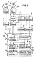
- Fig. 1 ein schematisches Blockschaltbild einer Einrichtung gemäß der Erfindung zum Bestimmen der Entfernung zwischen zwei Kraftfahrzeugen;
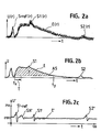
- Fig. 2a - 2e schematische Diagramme zur Erläuterung der Entfernungsbestimmung;
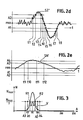
- Fig. 3 ein schematisches Diagramm einer Amplitudenhäufigkeitsverteilung eines differenzierten Empfangssignales.
- 1 shows a schematic block diagram of a device according to the invention for determining the distance between two motor vehicles;
- 2a-2e are schematic diagrams for explaining the distance determination;
- 3 shows a schematic diagram of an amplitude frequency distribution of a differentiated received signal.
In einer in Fig. 1 dargestellten Einrichtung zur Bestimmung der Entfernung zwischen einem Kraftfahrzeug und einem Hindernis, z. B. einem zweiten Kraftfahrzeug, wird von einem Taktgenerator 1 ein Lichtimpulssender 2 mit einer Laserdiode 3 angesteuert. Das ausgesendete Licht der Laserdiode fällt durch eine Ausgangsoptik 4. Ein geringer Leistungsanteil des Lichtimpulses wird über einen Lichtleiter 5 direkt auf eine Empfangsdiode 6 gerichtet, während die reflektierten Lichtimpulse und etwaiges rückgestreutes Licht über eine Eingangsoptik 7 auf die Empfangsdiode 6 gelangt. Das Ausgangssingal der Empfangsdiode 6 wird in einem Vorverstärker 6a verstärkt und einmal einem Trigger 8 sowie zwei Entfernungstoren 9 und 10 zugeführt. Über einen Torgenerator 11, der vom Trigger 8 angesteuert und vom Taktgenerator 1 auf "BEREIT" gestellt wird, werden die Entfernungstore 9 und 10 aufgetastet. Das Ausgangssignal der Entfernungstore 9 und 10 wird jeweils einem Integrator 12 bzw. 13 zugeführt, deren Ausgänge mit einer prozessorgesteuerten Auswerteschaltung 14 verbunden sind. Ferner werden der Auswerteschaltung noch die Steuereingänge und Signale des Taktgenerators 1 und des Torgenerators 11 zur Zeitsteuerung zugeführt.In a device shown in Fig. 1 for determining the distance between a motor vehicle and an obstacle, for. B. a second motor vehicle, a
Durch Einstellen der Frequenzen von Taktgenerator 1 und der Vorgabezeit für den Torgenerator 11 werden die Lichtimpulsfolge bzw. die Auftastfrequenz sowie zeitliche Lage der Entfernungstore 9 und 10 festgelegt. Jedes Entfernungstor empfängt daher Strahlung aus einem bestimmten Entfernungsbereich, der z. B. für Kraftfahrzeuge jeweils auf einen Meter festgelegt wird. Die Integratoren 12 und 13 dienen einmal zum Glätten des Signales und zum anderen zum Festlegen einer mittleren Amplitude innerhalb der einzelnen durch die Auftastzeitpunkte festgelegten Zeitabschnitte.By setting the frequencies of the
Für die Auswerteschaltung 14 sind weder die Prozessornoch die Zeitsteuerung dargestellt, sondern lediglich die für die Signalauswertung erforderlichen Schaltungen, die sämtlich z. B. mit einem Mikroprozessor realisiert werden können. Dies sind im einzelnen ein Differenzierer 15, eine Schaltung 16 zum Bestimmen von Amplitudenschwellen, eine signaldurchlässige Schwellwertschaltung 17, eine Schaltung 18 zum Impulsvergleich und eine Schaltung 19 zur Laufzeitmessung und Torgeneratorsteuerung und damit Entfernungsbestimmung. Die Entfernungswerte werden an einem Ausgang 20 angegeben.For the
Zusätzlich ist in der prozessorgesteuerten Auswerteschaltung 14 noch ein Integrator 21 vorgesehen, der mit den Ausgängen der beiden Integratoren 12 und 13 verbunden ist. An dessen Ausgang 22 wird ein Sichtweitensignal abgegeben, wie weiter unten erläutert.In addition, an
Die eigentliche Auswertung sei anhand der Signaldiagramme in den Fig. 2 und 3 erläutert:The actual evaluation is explained using the signal diagrams in FIGS. 2 and 3:
In Fig. 2a ist ein verrauschtes Empfangssignal E(r) als Spannung über der Zeit aufgetragen, wie es am Ausgang des Vorverstärkers 7 anliegt. Ein solches Empfangssignal kommt z. B. zustande, wenn Entfernungen im Nebel gemessen werden sollen. Man sieht zunächst das Referenzsignal S-ref(r), das durch die Einkopplung eines Teiles des ausgesendeten Lichtimpulses in die Empfangsdiode 6 zustande kommt. Der folgende Signalanstieg entspricht dem von einer Nebelwand rückgestreutem Licht. Innerhalb des im folgenden in der Spannung abfallenden verrauschten Empfangssignales ist ein erstes Nutzsignal S1(r) und später noch ein weiteres Nutzsignal S2(r) enthalten, die tatsächlich reflektierten Lichtimpulsen zuzuordnen sind.In FIG. 2a, a noisy received signal E (r) is plotted as a voltage over time, as it is present at the output of the preamplifier 7. Such a received signal comes, for. B. occurs when distances in the fog are to be measured. First of all, one sees the reference signal S-ref (r), which comes about by coupling a part of the emitted light pulse into the receiving diode 6. The following signal rise corresponds to the light scattered back by a fog wall. A first useful signal S1 (r) and later a further useful signal S2 (r) are contained within the noisy received signal which drops in voltage below and which are actually to be assigned to reflected light pulses.
In Fig. 2b ist das geglättete Empfangssignal E wiederum als Spannung U über der Zeit t aufgetragen. Dieses Spannungssignal liegt in der Schaltung gemäß Fig. 1 am Ausgang der Integratoren 12 bzw. 13 an. Es sei darauf hingwiesen, daß dieses geglättete Signal entsprechend der Entfernungstore ein gestuftes Signal ist, jedoch sind die Abstände zwischen den einzelnen Stufen so gering, daß hier die analoge Darstellung gewählt wurde.2b, the smoothed received signal E is in turn plotted as voltage U over time t. This voltage signal is present in the circuit according to FIG. 1 at the output of the
Man sieht wiederum zunächst das Referenzsignal S-ref, anschließend den Signalanstieg entsprechend dem von der Nebelwand rückgestreuten Licht und die Nutzsignale S1 und S2.The reference signal S-ref can again be seen, then the signal rise corresponding to the light scattered back from the fog wall and the useful signals S1 and S2.
Dieses geglättete Empfangssignal E wird anschließend im Differenzierer 15 differenziert. Auch dieses Signal ist an und für sich ein Stufensignal. Hier ist aus den obigen Gründen jedoch wiederum die analoge Darstellung gewählt. Das differenzierte Signal ist als Spannung Uʹ über der Zeit aufgetragen, wobei als Nullpunkt ein verschobener Spannungswert 0ʹ gewählt wird, um auch die durch die Differentiation negativen Signalanteile berücksichtigen zu können. Außerdem können durch einen nach oben verlegten Nullpunkt auch Bautoleranzen innerhalb der verwendeten Schaltungselemente ausgeglichen werden. Die Festlegung des verschobenen Nullpunktes 0ʹ erfolgt automatisch in der Schaltung, wie weiter unten erläutert.This smoothed received signal E is then differentiated in the
In dem Verlauf des differenzierten Empfangssignales Eʹ sieht man aufeinanderfolgend das differenzierte Referenzsignal Sʹ-ref sowie das erste und das zweite Nutzsignal S-1ʹ und S-2ʹ. Außerdem ist noch ein relativ hoher Signalbuckel SNʹ anschließend an das differenzierte Referenzsignal zu sehen. Dieser Signalbuckel entspricht dem Signalanstieg des Empfangssignales durch Rückstreuung an der Nebelwand.The differentiated reference signal Sʹ-ref and the first and second useful signals S-1ʹ and S-2ʹ can be seen in succession in the course of the differentiated received signal Eʹ. In addition, a relatively high signal hump SNʹ can be seen after the differentiated reference signal. This signal hump corresponds to the signal increase of the received signal due to backscattering on the fog wall.
Zur Festlegung des Nullbereiches und zur weiteren Auswertung des in Fig. 2c gezeigten differenzierten Empfangssignales Eʹ werden zunächst ein Amplitudenbereich und ein Entfernungsbereich bestimmt. Der zu berücksichtigende Amplitudenbereich wird z. B. in 256 Abschnitte, der zu berücksichtigende Enfernungsbereich in 100 Abschnitte aufgeteilt. Diese 100 Abschnitte sind jeweils gleich groß und entsprechend 100 Zeitabschnitten des in Fig. 2c gezeigten differenzierten Empfangssignales und somit auch 100 Entfernungstoren von z. B. jeweils 1 m Breite. In der Schaltung 16 zum Bestimmen der Amplitudenschwellen wird zunächst eine Amplitudenhäufigkeitsverteilung gemäß Fig. 3 bestimmt. Auf der Abszisse sind die Amplitudenwerte, auf der Ordinate ist die Anzahl N der in dem Signal gemäß Fig. 2c auftretenden Amplitudenwerte dargestellt. Es ergibt sich dann die Verteilungskurve V gemäß Fig. 3. Diese Verteilungskurve hat für den dargestellten Fall ein Maximum Nmax für den Amplitudenwert 80, sie fällt zu beiden Seiten dieses Wertes ab. Ein Vergleich der Figuren 2c und 3 zeigt, daß dieser Amplitudenwert dem oben erwähnten verschobenen Nullpunkt 0ʹ entspricht. Als nächstes werden sogenannte Rauschmittelwertamplituden R1 und R2 bestimmt, die auf der Verteilungskurve V liegen. Praxisgerechte Werte ergeben sich für den Ordinatenwert Nmax/2. Die Rauschmittelwertamplituden R1 und R2 liegen jeweils in einem Abstand a zu beiden Seiten des häufigst auftretenden Amplitudenwertes 80 und entsprechen in diesem Falle etwa den Amplituden 70 und 90. Diese Amplitudenwerte werden nochmals um einen bestimmten Betrag verringert bzw. vergrößert, in diesem Falle wiederum jeweils um den Abstand a. Diese Amplitudenwerte entsprechen dann einem unteren bzw. oberen Schwellwert A1 bzw. A2, in diesem Falle den Amplitudenwerten 60 bzw. 100. Aus der Verteilungskurve V ist ersichtlich, daß für diese Amplituden A1 und A2 innerhalb des differenzierten Empfangssignales Eʹ nur noch sehr geringe Singalanteile vorhanden sind. Durch Antragen eines weiteren Abstandes, z. B. wiederum des Abstandes a werden zweite untere und obere Amplitudenschwellen A3 und A4 bestimmt.To determine the zero range and for further evaluation of the differentiated received signal Eign shown in FIG. 2c, an amplitude range and a range are first determined. The amplitude range to be taken into account is e.g. B. in 256 sections, the distance range to be considered is divided into 100 sections. These 100 sections are each of the same size and correspond to 100 time sections of the differentiated received signal shown in FIG. 2c and thus also 100 distance gates of e.g. B. 1 m wide. An amplitude frequency distribution according to FIG. 3 is first determined in the
Diese Amplitudenschwellen A1 bis A4 werden in die signaldurchlässige Schwellwertschaltung 17 eingegeben, der das differenzierte Empfangssignal Eʹ gemäß Fig. 2c zugeführt wird. Aus den Figuren 2c und 2d ist ersichtlich, daß die Rauschanteile des differenzierten Empfangssignales Eʹ praktisch alle im Schwellenbereich zwischen A1 und A2 liegen und somit bei der nachfolgenden Auswertung nicht mehr berücksichtigt werden. Die jetzt noch berücksichtigten Signale können zunächst tatsächlichen Nutzsignalen zugeordnet werden; in Fig. 2d ist dieses für das Nutzsignal S2ʹ gezeigt.These amplitude thresholds A1 to A4 are input into the signal-
Bei gewissen Umständen kann es jedoch vorkommen, daß noch andere Signale durch die signaldurchlässige Schwellwertschaltung 17 hindurchgelassen werden. Dies betrifft hier den erwähnten Signalbuckel SNʹ. Um auch diese Signale auszuschalten, wird das Ausgangssignal der signaldurchlässigen Schwellwertschaltung 17 in die Schaltung 18 zum Impulsvergleich eingeleitet. In dieser Schaltung werden die Zeitpunkte bestimmt, an denen die noch berücksichtigten Signale die Schwellen A1 bis A4 schneiden. Für die schmalen, den reflektierten Lichtimpulsen zuzuordnenden Nutzsignale ergibt sich dann etwa ein Bild gemäß Fig. 2d für das Nutzsignal S2ʹ. Man sieht, daß diese Zeitpunkte t1 bis t8 in relativ geringen Zeitabständen aufeinander folgen. Aus dieser Zeitenfolge kann dann die Impulsform bestimmt und z. B. anhand empirischer Daten oder durch Vergleich mit der Impulsform des Referenzsignales S1-ref eindeutig einem Nutzsignal zugeordnet werden.In certain circumstances, however, it can happen that other signals are passed through the signal-
In Fig. 2e ist ein ähnliches Diagramm für den Signalbuckel SNʹ dargestellt, der die oberen Amplitudenschwellen A2 und A4 zu den Zeiten t9, t10, t11 und t12 schneidet. Der daraus berechnete Signalverlauf kann keinem reflektierten Lichtimpuls zugeordnet werden und wird daher für die weitere Signalauswertung nicht mehr berücksichtigt. Am Ausgang der Schaltung 18 zum Impulsvergleich liegen dann nur noch die Nutzsignale an. Die Entfernungsbestimmung wird dann in der Schaltung 19 mit Hilfe einer herkömmlichen Laufzeitmessung vorgenommen. Am Ausgang 20 der prozessorgesteuerten Auswerteschaltung 14 liegen somit nur die tatsächlichen Entfernungssignale an. Diese können in bekannter Weise weiter behandelt werden. so z. B. dem Fahrer angezeigt werden; außerdem ist es möglich, in gewissen Fällen z.B. direkt einen Bremsvorgang des Kraftfahrzeuges automatisch auszulösen. Da die Meßintervalle z. B. im Bereich von wenigen Millisekunden liegen, kann daraus auch eine Annäherungsgeschwindigkeit abgeleitet werden.2e shows a similar diagram for the signal hump SNʹ which intersects the upper amplitude thresholds A2 and A4 at times t9, t10, t11 and t12. The signal curve calculated from this cannot be assigned to a reflected light pulse and is therefore no longer taken into account for further signal evaluation. Only the useful signals are then present at the output of the
Die beschriebene Signalauswertung, die durch eine Signalauswertung der Amplitudenhäufigkeitsverteilung unterstützt wird, ist adaptiv und paßt sich automatisch den jeweiligen Verhältnissen an. Es wird automatisch ein Nullpunkt für die auszuwertenden Signale festgelegt, der anhängig ist von dem Rauschanteil, aber auch den Toleranzen der Bauelemente, die auf diese Weise ausgeglichen werden, so daß auch billige Bauelemente verwendet werden können. Durch die Unterstützung der Signalauswertung mit Hilfe der Signalhäufigkeitsverteilung werden die Rauschanteile des Empfangssignales praktisch eliminiert, so daß nur die scharfen Nadelimpulse entsprechend den reflektierten Lichtimpulsen verwertet werden. Ebenso werden automatisch die Amplitudenschwellen bestimmt, wobei es selbstverständlich möglich ist, noch mehr als die erwähnten vier Amplitudenschwellen zu bestimmen. Liegen z. B. günstige atmosphärische Bedingungen vor, so wird das Empfangssignal nicht so stark verrauscht sein, ebenso ergeben sich kaum Anteile, die durch rückgestreutes Licht verursacht werden. Dementsprechend wird dann auch die Amplitudenhäufigkeitsverteilung gemäß Fig. 3 um den Maximalwert einen wesentlich schmaleren Verlauf aufweisen.The signal evaluation described, which is supported by a signal evaluation of the amplitude frequency distribution, is adaptive and automatically adapts to the respective conditions. A zero point is automatically determined for the signals to be evaluated, which is dependent on the noise component, but also on the tolerances of the components, which are compensated in this way, so that inexpensive components can also be used. By supporting the signal evaluation with the aid of the signal frequency distribution, the noise components of the received signal are practically eliminated, so that only the sharp needle pulses corresponding to the reflected light pulses are used. Likewise, the amplitude thresholds are determined automatically, it being possible, of course, to determine even more than the four amplitude thresholds mentioned. Lying z. B. before favorable atmospheric conditions, the received signal will not be as noisy, and there are hardly any parts that are caused by backscattered light. Accordingly, the amplitude frequency distribution according to FIG. 3 will have a significantly narrower course around the maximum value.
Durch den Impulsvergleich mit Hilfe einer Überwachung der Zeitenfolge, wann die berücksichtigten Signale die einzelnen Amplitudenschwellen schneiden, können auch bei ungünstigen Bedingungen die Nutzsignale einwandfrei separiert werden. Fordert bei herkömmlichen Techniken, so z. B. einer Entfernungsbestimmung mit Hilfe von Radar, das Auflösungsvermögen und die Fehlerkennungsrate ein Signal/Rauschverhältnis von 10 dB, so kann mit der Erfindung einfach bei gleichen Randbedingungen ein Wert von minus 3 dB erreicht werden.By comparing the pulses with the aid of monitoring the sequence of times when the signals taken into account intersect the individual amplitude thresholds, the useful signals can be properly separated even under unfavorable conditions. Calls for conventional techniques, such. B. a distance determination with the help of radar, the resolution and the error detection rate a signal / noise ratio of 10 dB, so with the invention, a value of minus 3 dB can be easily achieved with the same boundary conditions.
Wie oben erwähnt, wird das geglättete Empfangssignal E zusätzlich noch dem Integrator 21 zugeführt. In diesem Integrator 21 wird zunächst eine Schwelle festgelegt, und zwar bevorzugt in der gleichen Weise, wie dieses für das differenzierte Empfangssignal beschrieben wird. Demgemäß wird eine Amplitudenhäufigkeitsverteilung des Empfangssignales und daraus eine Schwelle A5 bestimmt; vgl. Fig. 2b. Das über dieser Schwelle liegende Empfangssignal wird in den Integrator integriert; dieses Integral entspricht der in Fig. 2b schraffiert dargestellten Fläche F und ist ein Maß für die Rückstreuung des ausgesendeten Lichtes. Die Integration erfolgt jedoch nur dann, wenn das geglättete Empfangssignal E eine vorgegebene Zeitspanne T oberhalb dieser Schwelle A5 verbleibt. Im dargestellten Fall wird das Empfangssignal E zwischen den Zeiten tx und ty aufintegriert. Bei schlechten Sichtbedingungen wird diese Fläche F entsprechend groß sein, bei guten Sichtbedingungen entsprechend klein. Das am Ausgang 22 abgegebene Sichtweitensignal verhält sich entsprechend umgekehrt. Auch in diesem Falle ist es möglich, z. B. die Geschwindigkeit des Kraftfahrzeuges aufgrund des Sichtweitensignales auf einen vom Fahrer nicht zu beeinflussenden Wert zu begrenzen. Die erwähnte Schwellenbestimmung, die im übrigen auch empirisch erfolgen kann, ist unabhängig von der Signalverarbeitung zur Entfernungsbestimmung. Die Bewertung der Sichtweite jedoch erfolgt in Abhängigkeit von der Entfernung des auftretenden Nebelsignals.As mentioned above, the smoothed received signal E is additionally fed to the
Claims (10)
eine Differenzierschaltung (15) zum Differenzieren des Empfangssignales,
eine Schaltung (16) zum Ermitteln einer Amplitudenhäufigkeitsverteilung für das differenzierte Eingangssignal und zum Festlegen zumindest jeweils einer unteren und oberen Amplitudenschwelle (A1 bis A4) zu beiden Seiten des am häufigst auftretenden Amplitudenwertes,
eine Schwellwertschaltung (17) für das differenzierte Empfangssignal, deren Schwellen den festgelegten unteren und oberen Amplitudenschwellen entsprechen und
eine Schaltung zur Laufzeitmessung, die auf diejenige Signalanteile (S1ʹ, S2ʹ) innerhalb des differenzierten Empfangssignales (Eʹ) angewendet wird, die die unteren bzw. oberen Amplitudenschwellen unter- bzw. überschreiten.7.Device for determining the distance between two objects, in particular two motor vehicles, with a light pulse transmitter and a receiver and an evaluation circuit at the location of the first object for determining the propagation time of a light pulse from the first to the second object and back and then determining the distance by a processor-controlled evaluation circuit (14) which has the following circuits:
a differentiating circuit (15) for differentiating the received signal,
a circuit (16) for determining an amplitude frequency distribution for the differentiated input signal and for defining at least one lower and upper amplitude threshold (A1 to A4) on both sides of the most frequently occurring amplitude value,
a threshold circuit (17) for the differentiated received signal, the thresholds of which correspond to the defined lower and upper amplitude thresholds and
a circuit for transit time measurement, which is applied to those signal components (S1ʹ, S2ʹ) within the differentiated received signal (Eʹ) that fall below or exceed the lower or upper amplitude thresholds.
Applications Claiming Priority (2)
| Application Number | Priority Date | Filing Date | Title |
|---|---|---|---|
| DE3640449A DE3640449C1 (en) | 1986-11-27 | 1986-11-27 | Device for determining the distance between two objects, in particular two motor vehicles |
| DE3640449 | 1986-11-27 |
Publications (3)
| Publication Number | Publication Date |
|---|---|
| EP0269902A2 true EP0269902A2 (en) | 1988-06-08 |
| EP0269902A3 EP0269902A3 (en) | 1991-04-17 |
| EP0269902B1 EP0269902B1 (en) | 1993-08-25 |
Family
ID=6314841
Family Applications (1)
| Application Number | Title | Priority Date | Filing Date |
|---|---|---|---|
| EP87116277A Expired - Lifetime EP0269902B1 (en) | 1986-11-27 | 1987-11-05 | Process and device for measuring the distance between two objects, in particular between vehicles |
Country Status (2)
| Country | Link |
|---|---|
| EP (1) | EP0269902B1 (en) |
| DE (1) | DE3640449C1 (en) |
Cited By (14)
| Publication number | Priority date | Publication date | Assignee | Title |
|---|---|---|---|---|
| DE3810512A1 (en) * | 1988-03-28 | 1989-10-12 | Johann Hipp | Method and device for rangefinding using weak laser light pulses |
| EP0371197A2 (en) * | 1988-11-23 | 1990-06-06 | TEMIC TELEFUNKEN microelectronic GmbH | Image sensor |
| EP0377078A2 (en) * | 1988-11-23 | 1990-07-11 | TEMIC TELEFUNKEN microelectronic GmbH | Semiconductor image sensor, in particular for a CCD structure |
| EP0427969A2 (en) * | 1989-11-14 | 1991-05-22 | Leica AG | Pulse time of flight measurement device |
| WO1993001504A2 (en) * | 1991-07-02 | 1993-01-21 | Ltv Missiles And Electronics Group | Gate array pulse capture device |
| GB2275841A (en) * | 1993-03-02 | 1994-09-07 | Mitsubishi Electric Corp | Optoelectric distance measuring equipment |
| US5357331A (en) * | 1991-07-02 | 1994-10-18 | Flockencier Stuart W | System for processing reflected energy signals |
| GB2290918A (en) * | 1994-06-28 | 1996-01-10 | Mitsubishi Electric Corp | Lidar with interference detection |
| GB2302228A (en) * | 1990-04-07 | 1997-01-08 | Messerschmitt Boelkow Blohm | Proximity fuze |
| GB2314717A (en) * | 1996-06-24 | 1998-01-07 | Mitsui Shipbuilding Eng | Laser obstacle detection |
| EP0857982A2 (en) * | 1997-02-05 | 1998-08-12 | Volkswagen Aktiengesellschaft | Method and device for distance determination between vehicle and obstacle |
| GB2323491A (en) * | 1996-06-24 | 1998-09-23 | Mitsui Shipbuilding Eng | Laser obstacle detection |
| WO2006032854A1 (en) * | 2004-09-21 | 2006-03-30 | Instro Precision Limited | Particle detection device |
| EP2192419A3 (en) * | 2008-11-26 | 2012-07-25 | Robert Bosch GmbH | Method for dynamic calculation of noise levels |
Families Citing this family (12)
| Publication number | Priority date | Publication date | Assignee | Title |
|---|---|---|---|---|
| DE3912398A1 (en) * | 1989-04-15 | 1990-10-18 | Bayerische Motoren Werke Ag | OBJECT DETECTING DEVICE FOR MOTOR VEHICLES |
| DE3912397A1 (en) * | 1989-04-15 | 1990-10-18 | Bayerische Motoren Werke Ag | Object identification system for vehicle anticollision device - has response threshold for object spacing adjusted by manual programming |
| DE3922085C1 (en) * | 1989-07-05 | 1991-01-31 | Messerschmitt-Boelkow-Blohm Gmbh, 8012 Ottobrunn, De | Close distance measurer for two motor vehicles - sends light pulses and HF pulses for evaluation for safety precaution |
| DE4127168C2 (en) * | 1991-08-16 | 1994-07-07 | Spies Martin J Dipl Ing Fh | Signal processing for distance measurement |
| DE4442189C2 (en) * | 1994-11-28 | 2002-04-18 | Martin Spies | Distance measurement and selective information transfer system for automotive applications |
| DE19717399C2 (en) * | 1997-04-24 | 2001-05-23 | Martin Spies | Device for determining the distance and type of objects and the visibility |
| DE10004215C2 (en) * | 2000-02-01 | 2003-04-17 | Bosch Gmbh Robert | Use of an arrangement for length measurement and information transmission for a power tool |
| DE10162668B4 (en) * | 2001-12-19 | 2004-03-04 | Spies, Martin, Dipl.-Ing. (FH) | System for measuring the distance to objects by means of electromagnetic pulses |
| DE102006016026A1 (en) * | 2006-04-05 | 2007-10-11 | Sick Ag | Distance measuring device |
| DE102006049935B4 (en) * | 2006-10-19 | 2009-12-17 | Ingenieurbüro Spies GbR (vertretungsberechtigte Gesellschafter: Hans Spies, Martin Spies, 86558 Hohenwart) | Pulse propagation time sensor |
| DE102006053970A1 (en) * | 2006-11-16 | 2008-05-21 | Adc Automotive Distance Control Systems Gmbh | Object e.g. automatic-masking object, object characteristic and object position detecting method for use in driver assistance system, involves determining amplitude gradients of received electromagnetic radiation |
| DE102015215626B3 (en) * | 2015-08-17 | 2016-09-15 | Pmdtechnologies Gmbh | Sensor circuit and optical rangefinder with a non-linear photoreceiver |
Citations (5)
| Publication number | Priority date | Publication date | Assignee | Title |
|---|---|---|---|---|
| DE2921792A1 (en) * | 1978-05-30 | 1979-12-06 | Marconi Co Ltd | ARRANGEMENT FOR DETECTING THE PRESENCE OF NARROW PULSES IN AN ELECTRICAL SIGNAL |
| DE3020996A1 (en) * | 1980-06-03 | 1981-12-10 | Messerschmitt-Bölkow-Blohm GmbH, 8000 München | Flying missile arming distance detector - feeds reflected laser pulse to two distance gates with series-connected integrators whose voltages are evaluated |
| DE3130966A1 (en) * | 1981-08-05 | 1983-02-24 | Messerschmitt-Bölkow-Blohm GmbH, 8000 München | Sensor emitting electromagnetic waves and operating in accordance with the principle of reflection |
| DE3214938A1 (en) * | 1982-04-22 | 1983-10-27 | Siemens AG, 1000 Berlin und 8000 München | Circuit arrangement for separating user data signals and interference signals |
| DE3536659A1 (en) * | 1984-12-27 | 1986-07-03 | Impulsphysik Gmbh, 2000 Hamburg | DEVICE FOR CLOUD HEIGHT MEASUREMENT |
-
1986
- 1986-11-27 DE DE3640449A patent/DE3640449C1/en not_active Expired
-
1987
- 1987-11-05 EP EP87116277A patent/EP0269902B1/en not_active Expired - Lifetime
Patent Citations (5)
| Publication number | Priority date | Publication date | Assignee | Title |
|---|---|---|---|---|
| DE2921792A1 (en) * | 1978-05-30 | 1979-12-06 | Marconi Co Ltd | ARRANGEMENT FOR DETECTING THE PRESENCE OF NARROW PULSES IN AN ELECTRICAL SIGNAL |
| DE3020996A1 (en) * | 1980-06-03 | 1981-12-10 | Messerschmitt-Bölkow-Blohm GmbH, 8000 München | Flying missile arming distance detector - feeds reflected laser pulse to two distance gates with series-connected integrators whose voltages are evaluated |
| DE3130966A1 (en) * | 1981-08-05 | 1983-02-24 | Messerschmitt-Bölkow-Blohm GmbH, 8000 München | Sensor emitting electromagnetic waves and operating in accordance with the principle of reflection |
| DE3214938A1 (en) * | 1982-04-22 | 1983-10-27 | Siemens AG, 1000 Berlin und 8000 München | Circuit arrangement for separating user data signals and interference signals |
| DE3536659A1 (en) * | 1984-12-27 | 1986-07-03 | Impulsphysik Gmbh, 2000 Hamburg | DEVICE FOR CLOUD HEIGHT MEASUREMENT |
Cited By (28)
| Publication number | Priority date | Publication date | Assignee | Title |
|---|---|---|---|---|
| DE3810512A1 (en) * | 1988-03-28 | 1989-10-12 | Johann Hipp | Method and device for rangefinding using weak laser light pulses |
| EP0371197A2 (en) * | 1988-11-23 | 1990-06-06 | TEMIC TELEFUNKEN microelectronic GmbH | Image sensor |
| EP0377078A2 (en) * | 1988-11-23 | 1990-07-11 | TEMIC TELEFUNKEN microelectronic GmbH | Semiconductor image sensor, in particular for a CCD structure |
| EP0371197A3 (en) * | 1988-11-23 | 1990-11-28 | Messerschmitt-Bolkow-Blohm Gesellschaft Mit Beschrankter Haftung | Image sensor |
| EP0377078A3 (en) * | 1988-11-23 | 1990-11-28 | Messerschmitt-Bolkow-Blohm Gesellschaft Mit Beschrankter Haftung | Semiconductor image sensor, in particular for a ccd structure |
| EP0427969A2 (en) * | 1989-11-14 | 1991-05-22 | Leica AG | Pulse time of flight measurement device |
| EP0427969A3 (en) * | 1989-11-14 | 1992-08-19 | Leica Heerbrugg Ag | Pulse time of flight measurement device |
| GB2302228A (en) * | 1990-04-07 | 1997-01-08 | Messerschmitt Boelkow Blohm | Proximity fuze |
| GB2302228B (en) * | 1990-04-07 | 1997-07-09 | Messerschmitt Boelkow Blohm | Proximity fuse |
| WO1993001504A2 (en) * | 1991-07-02 | 1993-01-21 | Ltv Missiles And Electronics Group | Gate array pulse capture device |
| WO1993001504A3 (en) * | 1991-07-02 | 1993-03-18 | Ltv Missiles & Electronics | Gate array pulse capture device |
| US5357331A (en) * | 1991-07-02 | 1994-10-18 | Flockencier Stuart W | System for processing reflected energy signals |
| GB2275841B (en) * | 1993-03-02 | 1997-04-16 | Mitsubishi Electric Corp | Distance measuring equipment |
| US5523835A (en) * | 1993-03-02 | 1996-06-04 | Mitsubishi Denki Kabushiki Kaisha | Distance measuring equipment |
| GB2275841A (en) * | 1993-03-02 | 1994-09-07 | Mitsubishi Electric Corp | Optoelectric distance measuring equipment |
| GB2290918A (en) * | 1994-06-28 | 1996-01-10 | Mitsubishi Electric Corp | Lidar with interference detection |
| US5699151A (en) * | 1994-06-28 | 1997-12-16 | Mitsubishi Denki Kabushiki Kaisha | Distance measurement device |
| GB2290918B (en) * | 1994-06-28 | 1999-03-10 | Mitsubishi Electric Corp | Distance measurement device |
| GB2323491A (en) * | 1996-06-24 | 1998-09-23 | Mitsui Shipbuilding Eng | Laser obstacle detection |
| GB2314717A (en) * | 1996-06-24 | 1998-01-07 | Mitsui Shipbuilding Eng | Laser obstacle detection |
| GB2323491B (en) * | 1996-06-24 | 1999-03-31 | Mitsui Shipbuilding Eng | Laser obstacle detection method and sensor |
| GB2314717B (en) * | 1996-06-24 | 1999-03-31 | Mitsui Shipbuilding Eng | Laser obstacle detection method and sensor |
| US5970433A (en) * | 1996-06-24 | 1999-10-19 | Mitsui Engineering & Shipbuilding Co. Ltd. | Laser obstacle detection method and sensor |
| SG97753A1 (en) * | 1996-06-24 | 2003-08-20 | Mitsui Shipbuilding Eng | Laser obstacle detection method and sensor |
| EP0857982A2 (en) * | 1997-02-05 | 1998-08-12 | Volkswagen Aktiengesellschaft | Method and device for distance determination between vehicle and obstacle |
| EP0857982A3 (en) * | 1997-02-05 | 1999-10-27 | Volkswagen Aktiengesellschaft | Method and device for distance determination between vehicle and obstacle |
| WO2006032854A1 (en) * | 2004-09-21 | 2006-03-30 | Instro Precision Limited | Particle detection device |
| EP2192419A3 (en) * | 2008-11-26 | 2012-07-25 | Robert Bosch GmbH | Method for dynamic calculation of noise levels |
Also Published As
| Publication number | Publication date |
|---|---|
| EP0269902A3 (en) | 1991-04-17 |
| DE3640449C1 (en) | 1988-06-30 |
| EP0269902B1 (en) | 1993-08-25 |
Similar Documents
| Publication | Publication Date | Title |
|---|---|---|
| EP0269902B1 (en) | Process and device for measuring the distance between two objects, in particular between vehicles | |
| EP2698648B1 (en) | Method for classifying vehicles in motion | |
| DE3420004C2 (en) | ||
| DE3238022C2 (en) | Device for detecting moving obstacles for vehicles | |
| DE102005019269B4 (en) | Device for detecting a preceding vehicle | |
| EP1544643B1 (en) | Method and device for the surveillance of an area with several light emitters arranged side by side | |
| DE2544842A1 (en) | METHOD AND CIRCUIT ARRANGEMENT FOR EVALUATING SIGNAL PULSE SEQUENCES, IN PARTICULAR RADAR PULSE SEQUENCES | |
| EP2698646A1 (en) | Method for classifying moving vehicles by tracking a position size of the vehicle | |
| DE4023538A1 (en) | COLLISION WARNING DEVICE | |
| DE3028076A1 (en) | RADAR SYSTEM FOR VEHICLES | |
| DE102004047087A1 (en) | Method for object verifaction in radar systems for motor vehicles | |
| DE3940404A1 (en) | METHOD AND DEVICE FOR DOUBLE EFFECT SPEED MEASUREMENT | |
| DE102006012413B4 (en) | Object detection device for a vehicle | |
| EP3435117A1 (en) | Sensor and method for detecting and determining the distance between objects | |
| DE10026032A1 (en) | Device and method for determining distance and speed | |
| DE2655847A1 (en) | AUTOMATIC BRAKING SYSTEM FOR ROAD VEHICLES | |
| DE4124192A1 (en) | Optical rangefinder for spacing between moving road vehicles - measures propagation time of infrared reflection from preceding vehicle, and gives warning of too near approach | |
| EP0571566B1 (en) | Ultrasonic distance-measuring equipment | |
| DE2158793B2 (en) | Device for measuring and displaying the distance and / or the change in distance between a motor vehicle and an obstacle | |
| DE19828160B4 (en) | Method for automatic recognition of the main roadway in a multi-lane route | |
| DE102015119658A1 (en) | Method for detecting an environmental region of a motor vehicle with object classification, control device, driver assistance system and motor vehicle | |
| DE19745493A1 (en) | Proximity sensor and person recognition method | |
| EP0857982B1 (en) | Method and device for distance determination between vehicle and obstacle | |
| WO2019101506A1 (en) | Method for operating a lidar sensor and lidar sensor | |
| EP2977786A1 (en) | Distance measuring sensor for detecting and ranging objects |
Legal Events
| Date | Code | Title | Description |
|---|---|---|---|
| PUAI | Public reference made under article 153(3) epc to a published international application that has entered the european phase |
Free format text: ORIGINAL CODE: 0009012 |
|
| AK | Designated contracting states |
Kind code of ref document: A2 Designated state(s): CH DE FR GB IT LI SE |
|
| PUAL | Search report despatched |
Free format text: ORIGINAL CODE: 0009013 |
|
| AK | Designated contracting states |
Kind code of ref document: A3 Designated state(s): CH DE FR GB IT LI SE |
|
| 17P | Request for examination filed |
Effective date: 19910503 |
|
| 17Q | First examination report despatched |
Effective date: 19920228 |
|
| RAP1 | Party data changed (applicant data changed or rights of an application transferred) |
Owner name: DEUTSCHE AEROSPACE AKTIENGESELLSCHAFT |
|
| RBV | Designated contracting states (corrected) |
Designated state(s): CH FR GB LI |
|
| GRAA | (expected) grant |
Free format text: ORIGINAL CODE: 0009210 |
|
| REG | Reference to a national code |
Ref country code: DE Ref legal event code: 8566 |
|
| AK | Designated contracting states |
Kind code of ref document: B1 Designated state(s): CH FR GB LI |
|
| ET | Fr: translation filed | ||
| GBT | Gb: translation of ep patent filed (gb section 77(6)(a)/1977) |
Effective date: 19931011 |
|
| PLBE | No opposition filed within time limit |
Free format text: ORIGINAL CODE: 0009261 |
|
| STAA | Information on the status of an ep patent application or granted ep patent |
Free format text: STATUS: NO OPPOSITION FILED WITHIN TIME LIMIT |
|
| 26N | No opposition filed | ||
| REG | Reference to a national code |
Ref country code: GB Ref legal event code: 732E |
|
| REG | Reference to a national code |
Ref country code: GB Ref legal event code: IF02 |
|
| PGFP | Annual fee paid to national office [announced via postgrant information from national office to epo] |
Ref country code: GB Payment date: 20041025 Year of fee payment: 18 |
|
| PGFP | Annual fee paid to national office [announced via postgrant information from national office to epo] |
Ref country code: CH Payment date: 20041109 Year of fee payment: 18 |
|
| PGFP | Annual fee paid to national office [announced via postgrant information from national office to epo] |
Ref country code: FR Payment date: 20041112 Year of fee payment: 18 |
|
| PG25 | Lapsed in a contracting state [announced via postgrant information from national office to epo] |
Ref country code: GB Free format text: LAPSE BECAUSE OF NON-PAYMENT OF DUE FEES Effective date: 20051105 |
|
| PG25 | Lapsed in a contracting state [announced via postgrant information from national office to epo] |
Ref country code: CH Free format text: LAPSE BECAUSE OF NON-PAYMENT OF DUE FEES Effective date: 20051130 Ref country code: LI Free format text: LAPSE BECAUSE OF NON-PAYMENT OF DUE FEES Effective date: 20051130 |
|
| REG | Reference to a national code |
Ref country code: CH Ref legal event code: PL |
|
| GBPC | Gb: european patent ceased through non-payment of renewal fee |
Effective date: 20051105 |
|
| PG25 | Lapsed in a contracting state [announced via postgrant information from national office to epo] |
Ref country code: FR Free format text: LAPSE BECAUSE OF NON-PAYMENT OF DUE FEES Effective date: 20060731 |
|
| REG | Reference to a national code |
Ref country code: FR Ref legal event code: ST Effective date: 20060731 |