EP0276141A2 - Apparatus for mounting chip device on printed circuit board - Google Patents
Apparatus for mounting chip device on printed circuit board Download PDFInfo
- Publication number
- EP0276141A2 EP0276141A2 EP88300457A EP88300457A EP0276141A2 EP 0276141 A2 EP0276141 A2 EP 0276141A2 EP 88300457 A EP88300457 A EP 88300457A EP 88300457 A EP88300457 A EP 88300457A EP 0276141 A2 EP0276141 A2 EP 0276141A2
- Authority
- EP
- European Patent Office
- Prior art keywords
- chip device
- tape
- chip
- suction
- mounting
- Prior art date
- Legal status (The legal status is an assumption and is not a legal conclusion. Google has not performed a legal analysis and makes no representation as to the accuracy of the status listed.)
- Withdrawn
Links
Images


Classifications
-
- H—ELECTRICITY
- H05—ELECTRIC TECHNIQUES NOT OTHERWISE PROVIDED FOR
- H05K—PRINTED CIRCUITS; CASINGS OR CONSTRUCTIONAL DETAILS OF ELECTRIC APPARATUS; MANUFACTURE OF ASSEMBLAGES OF ELECTRICAL COMPONENTS
- H05K13/00—Apparatus or processes specially adapted for manufacturing or adjusting assemblages of electric components
- H05K13/04—Mounting of components, e.g. of leadless components
- H05K13/0417—Feeding with belts or tapes
-
- Y—GENERAL TAGGING OF NEW TECHNOLOGICAL DEVELOPMENTS; GENERAL TAGGING OF CROSS-SECTIONAL TECHNOLOGIES SPANNING OVER SEVERAL SECTIONS OF THE IPC; TECHNICAL SUBJECTS COVERED BY FORMER USPC CROSS-REFERENCE ART COLLECTIONS [XRACs] AND DIGESTS
- Y10—TECHNICAL SUBJECTS COVERED BY FORMER USPC
- Y10T—TECHNICAL SUBJECTS COVERED BY FORMER US CLASSIFICATION
- Y10T156/00—Adhesive bonding and miscellaneous chemical manufacture
- Y10T156/17—Surface bonding means and/or assemblymeans with work feeding or handling means
- Y10T156/1702—For plural parts or plural areas of single part
- Y10T156/1744—Means bringing discrete articles into assembled relationship
- Y10T156/1768—Means simultaneously conveying plural articles from a single source and serially presenting them to an assembly station
-
- Y—GENERAL TAGGING OF NEW TECHNOLOGICAL DEVELOPMENTS; GENERAL TAGGING OF CROSS-SECTIONAL TECHNOLOGIES SPANNING OVER SEVERAL SECTIONS OF THE IPC; TECHNICAL SUBJECTS COVERED BY FORMER USPC CROSS-REFERENCE ART COLLECTIONS [XRACs] AND DIGESTS
- Y10—TECHNICAL SUBJECTS COVERED BY FORMER USPC
- Y10T—TECHNICAL SUBJECTS COVERED BY FORMER US CLASSIFICATION
- Y10T29/00—Metal working
- Y10T29/53—Means to assemble or disassemble
- Y10T29/5313—Means to assemble electrical device
- Y10T29/53191—Means to apply vacuum directly to position or hold work part
Definitions
- the present invention relates to an apparatus for mounting automatically various kinds of chip devices on a printed circuit board.
- Chip Mounter Such an apparatus is generally called “Chip Mounter” and has been used for mounting active chip devices such as chip IC, chip transistor and chip diode as well as passive chip devices such as chip resistor, chip capacitor and chip coil.
- chip mounters have been developed. Usually a number of chip devices of the same kind are arranged in a tape which is wound as a coil.
- a known chip mounter a plurality of tape coils are set on a plurality of tape units arranged side by side and these tape units are moved with respect to a mounting head. After a tape unit on which a tape coil having desired chip devices has been indexed into the mounting head, one chip device is supplied from the tape unit to the mounting head. Then the mounting head is indexed at a given position on a printed circuit board placed on an XY table and the chip device is mounted on the printed circuit board.
- the chip device to be mounted is held at a lower end of the mounting head with the aid of the suction force, and therefore the number of different kinds of chip devices which can be mounted by the single mounting head could not be made large. Therefore, there has been also proposed a chip mounter in which a plurality of mounting units each being composed of tape unit, mounting head and XY table are arranged in series with each other and a printed circuit board is transported through successive mounting units, while desired chip devices are mounted on the circuit board in respective mounting units.
- chip mounter including a plurality of mounting heads each holding chip devices having different sizes and shapes and a desired mounting head is selectively used in accordance with a chip device to be mounted.
- the apparatus may be made rather small, but the construction of the mounting head assembly becomes quite complicated and the mounting rate becomes low, because the changing of mounting heads requires a relatively long time.
- the present invention has for its object to provide an apparatus for mounting automatically different kinds of chip devices on a printed circuit board at a high speed, while the whole apparatus can be made small in size, simple in construction and cheap in cost.
- an apparatus for mounting automatically chip devices on a printed circuit board comprises supplying means for supplying chip devices one by one in an upside down fashion in a predetermined order; chip device feeding means for receiving and holding the chip devices supplied from the chip device supplying means with the aid of the suction force, while the chip devices are held in the upside down fashion, and feeding the chip devices thus held into a first transporting position; turning over means for receiving the chip device indexed at the first transporting position with the aid of the suction force, turning over the chip device thus held and transporting the chip device into a second transporting position; and mounting means for receiving the chip device indexed at the second transporting position with the aid of the suction force, transporting the chip device thus held on a printed circuit board at a predetermined position thereof and placing the chip device on the printed circuit board.
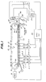
- FIG. 1 is a schematic view showing schematically the basic construction of an embodiment of the chip mounter according to the invention.
- a tape unit mounting unit 1 comprises a plurality of tape units 2-1 ⁇ 2-n arranged side by side in a horizontal direction at a constant pitch. In each tape unit there is arranged a tape containing a number of chip devices.
- a tape 3 comprises a containing tape 3a having a number of depressions 4 formed therein at a constant pitch in the longitudinal direction, and a cover tape 3b which is adhered onto the containing tape 3a in a removable manner.
- Chip devices 5 of the same kind are provided in respective depressions 4 and the tape 3 is wound on a real 6.
- the containing tape 3a there are formed holes 3c along one side thereof at positions between successive depressions 4.
- Fig. 1 different kinds of tapes may be provided in respective tape units 2-1 ⁇ 2-n or a plurality of chip devices of the same kind may be provided in a plurality of tape units, if chip devices of the relevant kind are frequently used.
- the tape 3 provided in the tape unit 2 is selectively fed in a stepwise manner, while the cover tape 3b is peeled out of the containing tape 3a. In this manner, a chip device can be fed into a feeding unit 8 one by one.
- the feeding unit 8 comprises a pair of sprockets 9a and 9b, endless chain 10 provided around the sprockets, suction chamber 11 arranged along the chain and a number of carriers 12 which are secured to the chain in such a manner that the carriers are sled on the suction chamber.
- the carriers 12 are arranged at the same pitch as that of the tape units 2-1 ⁇ 2-n.
- a top surface of the suction chamber 11 there are formed a number of suction holes lla along the longitudinal direction thereof.
- the suction chamber 11 is coupled with a suction pump 13 so that the space inside the chamber is maintained at a negative pressure of, for example, -100 mmHg and air is sucked within the chamber via the holes 11a.
- the negative pressure within the chamber 11 may be set to a value within a range of -60 ⁇ -200 mmHg.
- the suction holes 11a are formed at such a pitch that the carrier 12 can always cover at least one suction hole.
- a suction buffer which is communicated with suction openings 12a. Therefore, the suction pump 13 sucks the air through suction openings 12a, suction buffer, suction hole 11a and chamber 11.
- the chain 10 is rotated as shown by an arrow A in a stepwise manner by means of a motor 14 coupled with the sprocket 9a such that successive carriers 12 are indexed with respect to successive tape units 2-1 to 2-n.
- a motor 14 coupled with the sprocket 9a such that successive carriers 12 are indexed with respect to successive tape units 2-1 to 2-n.
- the chip device held on the carrier 12 is transported into a turn over unit 15 including a turnover device 16 which is coupled with a suction pump 17.
- the turnover device 16 sucks the chip device held on the carrier 12 positioned at a first transporting position 18a with a suction force which is higher than the suction force by means of which the carrier retains the chip device.
- This former suction force may be set to a value within a range of -300 ⁇ -500 mmHg. Therefore, the chip device is transferred from the carrier 12 into the turnover device. 16.
- the turnover device turns over the chip device by 180° about an axis extending horizontally. Therefore, the top surface of the chip device faces upward.
- the chip device is fed into a second transporting position 18b. At this second transporting position, the chip device is transferred from the turnover device into a mounting unit 19.
- the mounting unit 19 comprises a mounting head 20 which holds the chip device at its lower end with the aid of the suction force and places the chip device thus held on a printed circuit board 22 mounted on an XY table 21.
- the mounting head 20 is moved by a mounting head driving device 23 horizontally between the second transporting position 18b and a mounting position 18c as well as vertically at respective positions 18b and 18c. Further in order to orient the chip device into a desired direction, the mounting head 20 is rotated about a vertical axis.
- the mounting head is coupled with a suction pump 24 which generates a negative pressure of -300 ⁇ -500 mmHg.
- the suction force of the turn over unit 15 is stopped or decreased, and further after the chip device has been placed on the printed circuit board 22, the suction force of the mounting head is stopped or reduced.
- a syringe containing an adhesive agent is moved downward and a given amount of adhesive agent is applied on a given position of the printed circuit board by actuating the syringe.
- the mounting head 20 is moved downward and the chip device held at its tip is placed on the printed circuit board at the position on which the adhesive agent has been applied. In this manner, the chip device can be mounted and fixed on the printed circuit board.
- the tape units 2-1 to 2-n, chain driving motor 14, suction pumps 17 and 24, head driving device 23 and XY table driving device 25 are controlled by a control unit 26.
- the profiling mode Prior to effect the actual mounting, it is necessary to determine which chip devices are mounted at which positions on the printed circuit board. This may be effected by the profiling mode or by the programming mode. In the profiling mode, at first the mounting head is indexed manually at a given position on the printed circuit board and then a kind of chip device to be mounted at the relevant position is entered by operating a key board. In the present embodiment, the profiling mode is adopted.
- Figs. 3A and 3B are plan and front views, respectively showing a general construction of the chip mounter of the present embodiment.
- Four mounting devices each including respective mounting heads are arranged substantially symmetrically with respect to the common mounting position 18c.
- the construction of these mounting devices is same, so that in Figs. 3A and 3B the construction of a single mounting device is illustrated.
- the mounting unit comprises tape unit mounting unit 1, feeding unit 8, turning over unit 15 and mounting unit 19.
- carries 12 in each feeding units 8 are driven independently from each other by means of separate driving devices, and further in order to transfer a chip device held on the carrier 12 to a turnover device 16 of the turning over unit 15 at a transporting position 18a in a positive manner, there are provided two centering devices 300-1 and 300-2 having a simple construction by means of which the chip device held on the carrier is clamped in X direction parallel to the feeding direction as well as Y direction perpendicular to the X direction.
- centering device 301 and suction nozzle exchanging device 302 between the second transporting position 18b and the mounting position 18c.
- the centering device 301 By means of the centering device 301 the position of a chip device sucked at the tip of suction nozzle secured to the lower end of the mounting head 20 is corrected in the X and Y directions.
- the nozzle exchanging device 302 By means of the nozzle exchanging device 302 a desired suction nozzle is selectively secured to the mounting head 20 in accordance with shape and size of chip devices to be mounted.
- the remaining mounting devices have the same construction as that mentioned above, but a mounting device for mounting special chip devices such as QFP (Quad Flat Package) which includes a number of lead wires extending substantially horizontally from side walls does not comprise the mechanical centering devices 300-1 and 300-2, but includes an electrical centering device comprising an image pick-up device and an image signal processing device.
- QFP Quad Flat Package
- the tape unit mounting unit 1 operates to drive selectively a plurality of tape units 2-1 ⁇ 2-n which are arranged along the moving path of the carriers 12 at a constant pitch by driving a tape unit driving device 303 and a chip device contained in a tape is supplied onto a carrier 12 of the feeding unit 8 in a turn over fashion. That is to say, on the carrier 12 the rear surface of chip device faces upward.
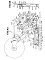
- Figs. 4A and 4B are front and side views, respectively illustrating the tape unit 2.
- a base 305 is rotatably secured the reel 6 on which the tape 3 is wound.
- the tape 3 is guided out of the reel 6 via rollers 306a, 306b and guide 307a to a transferring base 308 provided at a lower portion of the base 305 for defining a level of the chip device transferring path in such a manner that the cover tape 3b faces downward.
- a recess 308b for supplying a chip device via a slide surface 308a.
- the tape pusher 309 is journaled by a shaft 310 and is biased by a coiled spring 311 such that the tape 3 is urged against the slide surface 308a.
- the cover tape 3b of tape 3 is turned at the recess 308b, so that a chip device 5 contained in a depression 4 of the containing tape 3a is dropped onto a carrier 12 via the recess 308b, while the cover tape 3b is peeled off the containing tape 3a.
- the slide surface 308a formed in the transferring base 308 is thinned toward the recess 308b.
- the cover tape 3b peeled off the tape 3 at the transferring base 308 is wound on a take-up reel 312 via rollers 306c and 306d.
- the take-up reel 312 is secured to a reel bracket 313 which is arranged rotatably about a shaft 313a secured to the base 305.
- the reel bracket 313 comprises a spring pin 313b which is engaged with the take-up reel 312, and an O-ring 313c which is made in contact with the take-up reel.
- a gear 313d which is engaged with a ratchet 314a provided on the base 305 so that the reel bracket 313 can rotate only in the clockwise direction in Fig. 4A, i.e.
- the feed plate 315 can be selectively rotated by means of the tape unit driving device 303 as will be explained later.
- the containing tape 3a is fed in the leftward in Fig. 4A by means of sprocket 316 and tape guide 307b.
- the sprocket 316 serves to feed the tape 3 in a stepwise manner.
- the containing tape 3a is urged against the sprocket 316 by a tape pusher 317 and a gear 316a of the sprocket is inserted into the hole 3c.
- the tape pusher 317 is biased by a coiled spring 318 to be urged against the containing tape 3a.
- the feeding sprocket 316 is coupled a sprocket ring 319 via a one-way clutch and the sprocket ring is selectively rotated by the tape unit driving device 303 as will be explained later. Then the tape 3 is fed by one pitch and the cover tape 3b is peeled off the containing tape 3a at the transferring base 308 and the chip device 5 is supplied onto the carrier 12 as shown in Fig. 4D. As illustrated in Fig. 4C, a positioning stopper 320 provided on the bracket 305 is urged against the feeding sprocket 316.
- a link 321 is provided on the base 305 rotatable about a shaft 321a.
- One end of the link 321 is rotated in the clockwise direction in Fig. 4A by means of the tape unit driving device 303.
- To the other end of the link 321 there are secured one ends of links 322 and 323 rotatably, and the other end of the link 322 is engaged with the feed plate 315 by means of pin 322a and recess 315a.
- the other end of the link 323 is engaged with the sprocket ring 319 via a pin 323a.
- the link 321 is biased by a coiled spring 324 to rotate in the counter clockwise direction in Fig. 4A.
- the feed plate 315 is biased by a coiled spring 325 to rotate in the clockwise direction in Fig. 4A, the spring 325 being weaker than the spring 324. Therefore, in the normal condition of the link 321 shown by a solid line in Fig. 4A, the take-up reel 312 is biased by the spring 325 to rotate in the clockwise direction, so that the cover tape 3b is subjected to the tension applied to the take-up reel 312.
- the chip device 5 stored in the tape 3 is supplied through the recess 308b of the transferring base 308 on the carrier 12 in the upside down fashion.
- the link 321 is returned into the original position, only the sprocket ring 319 is rotated in the counter clockwise direction. Further, since the rotation of the reel bracket 313 in the counter clockwise direction is inhibited by the ratchet 314a, only the feed plate 315 and ratchet 314b are rotated in the counter clockwise direction.
- a shutter plate 326 is journaled to the roller 306b and an engaging member 326a is secured to the shutter plate at such a position that the member 326a is engaged with a portion of the tape 3 between the rollers 306a and 306b.
- the shutter plate 326 is rotated in the counter clockwise direction due to the force of gravity until it is engaged with a stopper 327 secured to the base 305.
- a detection light path is interrupted by the shutter plate.
- the detection light path is defined by light emitting element and light receiving element. When the light receiving element detects the interruption of the detection light path, there is generated an alarm.
- a guide base 329 is provided on the base 305 with the aid of a shaft 328 at a lower portion of the base which is opposite to the portion at which the transferring base 308 is provided.
- the other end of the guide base 329 is engaged with a guide 333a secured to a base 322 of the tape unit mounting unit 1.
- a coiled spring 334 Between the clamp lever 330 and clamp lock 331 is arranged a coiled spring 334,so that when the clamp lever 330 is rotated in the counter clockwise direction, the clamp lock 331 is rotated in the counter clockwise direction due to the force of the spring 334 and is disengaged from the engaging plate 333b.
- a coiled spring 335 Between the guide base 329 and the base 305 is arranged a coiled spring 335 for biasing the base 305 to rotate in the counter clockwise direction about a shaft 328. Therefore, when the tape unit driving device 303 is in the non-operating condition, the recess 308b of the transferrring base 308 is sufficiently spaced from the carrier traveling path so that the carriers 12 can be moved smoothly.
- the rotation of the base 305 is limited by the engagement of an engaging member 336 secured to the base 305 with a stopper 337 secured to the guide base 329.
- the base 305 is rotated in the clockwise direction against the force of the spring 335 in conjunction with the rotation of the link 321 due to the operation of the tape unit driving device 303 and the recess 308b of the transferring base 308 is moved closer to the carrier 12. Then the link 321 is further rotated to supply the chip device 5 onto the carrier 12.
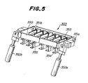
- Fig. 5 is a perspective view showing a principal construction of the tape unit driving device 303.
- the tape unit driving device 303 comprises a pushing plate 350 which extends in the direction in which the tape units 2 are arranged side by side.
- the pushing plate 350 is rotatably supported by shafts 351a and 351b at its both ends and is rotated by air cylinders 352a and 352b.
- a plurality of one-shot units 353 are provided in accordance with respective tape units 2 arranged in the tape unit mounting unit 1.
- the one-shot unit 353 comprises a selection arm 354 which is slidably engaged with the lower end of the pushing plate 350 by means of a pin 355.
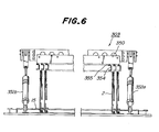
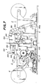
- Figs. 6 and 7 are front and side views illustrating the tape unit driving unit 303.
- the left-hand driving device is shown as a cross sectional view.
- the pushing plate 350 is biased by a coiled spring 356 to rotate downward and the selection arms 354 for respective one-shot units 353 are slidably hung from the pushing plate via the pins 355.
- the pushing plate 350 in the left-hand driving device 303 is in a normal position, while the pushing plate in the right-hand driving device is in the descendant position.
- Fig. 8 is a side view of the one-shot unit 353.
- the one-shot unit 353 comprises a base 360 and a lever 362 journaled to a shaft 361 secured to the base 360.
- One end of the selection arm 354 is journaled to one end of the lever 362.
- To the one end of the lever 362 is connected a coiled spring 363 to bias the lever to rotate in the counter clockwise direction in Fig. 8. This rotational movement is limited by a stopper 364.
- a solenoid 365 is secured to the base 360 and a plunger 365a of solenoid is coupled with the lever 362 at a position between the fitting positions to the shaft 361 and selection arm 354, respectively.
- the solenoid 365 When the solenoid 365 is energized, the lever 362 is rotated in the counter clockwise direction against the force of the spring 363 so that the link 321 is rotated via the engagement of the selection arm with the link.
- the selection arm 354 is hung from the pushing plate 350 by means of the pin 355. That is to say, one end of the pin 355 is secured to the lower edge of the pushing plate 350 and the other end of the pin is inserted into an elongated hole formed in an upper surface of the selection arm 354.
- a guide pin 366 is secured to the selection arm 354 and is engaged with a dog 367 formed in the base 360.
- the solenoid 365 is energized, and the selection arm 354 is moved into the selecting position, the selection arm is remained in this position. Further, when the pushing plate 350 is moved downward, the guide pin 366 is moved along the dog 367.
- the selection arm 354 is disengaged from the link 321 due to the action of the spring 363 and the guide pin 366 passes through a valley portion 367c of the dog 367. Thereafter, the guide pin 366 is moved upward along an upright portion 367c opposite to the upright portion 367b in accordance with the upward movement of the pushing plate 350 and is returned into a home position. Therefore, in the selection mode, the guide pin 366 turns around the dog 367 by one revolution. It should be noted that when a tape unit is not selected, the lever 362 is in such a position that it is urged against the stopper 364. In this condition, the guide pin 366 is moved along the upright portion 367d and the selection arm 354 is not brought into contact with the link 321 of the relevant tape unit.
- the selection arm 354 can be remained in the selecting position by energizing the solenoid 365 for a short time, and thus the power consumption can be saved.
- the feeding unit 8 comprises an endless chain 10, a number of carriers 12 secured to the chain and a suction chamber 11. While the carriers 12 are fed on the suction chamber 11, one or more chip devices 5 are supplied on one or more carriers 12 from the tape unit mounting unit 1 and the chip device thus supplied is fed through the transporting position 18a to the turnover device 16.
- the simple centering devices 300-1 and 300-2 for centering the chip devices in the X and Y directions, respectively.
- the carriers 12 of each mounting units have the substantially same construction.
- Fig. 9A is a plan view showing the carrier 12 and Fig. 9B is a cross sectional view cut along a line I-I in Fig. 9A.
- the carrier 12 is formed by a mold of electrically conductive resin.
- holes 370a and 370b for securing the carrier to the chain 10.
- a buffer 371 which maintains the negative pressure within the suction chamber 11.
- five small holes 372 at a central area thereof and eight large holes 373 in a symmetrical manner.
- the small hole 372 has a diameter of 0.3 mm at the upper surface and of 0.6 mm at the lower surface
- the large hole 373 has a diameter of 0.5 mm at the upper surface and of 1.0 mm at the lower surface. That is to say, these holes 372 and 373 have a tapered configuration.
- the carrier 12 is made of a conductive resin, undesired electrostatic charge can be effectively prevented. Further, the carrier 12 can be manufactured in an easy and less expensive manner by the mold. Moreover, since the small and large holes 372 and 373 have the tapered configuration, it is possible to suck not only small chip devices, but also large chip devices in a positive manner.
- the carrier 12 is secured to the chain 10 by means of fitting member 375, colors 376 and bolts 377a and 377b.
- the suction chamber 11 has a cross section of 12 mm ⁇ 12 mm, and in an upper surface there are formed suction holes 11a having a diameter of 1.0 mm at a constant pitch. It should be noted that the pitches of the suction holes 11a and carriers 12 and a length of the buffer 371 formed in the rear surface of the carrier are so determined that at least one suction hole is always communicated with the buffers of the carriers so that the air is always sucked through the suction holes 372 and 373 formed in the carrier 12.
- the chamber 11 is coupled with the suction pump 13 (see Fig. 11) so that the pressure within the buffer 371 is maintained at a given negative pressure within -60 to -200 mmHg.
- Fig. 11 is a perspective view showing a principal construction of the carrier driving unit.
- the endless chain 10 extended between the sprockets 9a and 9b is moved by an independent driving unit 400.
- the driving unit 400 comprises a servomotor 401 for rotating a pulley 402 which is coupled via a timing belt 404 with a pulley 403 coaxially secured to the sprocket 9a.
- the chain 10 can be rotated by the motor 401 by means of the pulley 402, timing belt 404, pulley 403 and sprocket 9a.
- each driving unit 8 since the chains 10 in each driving units 8 are driven by respective driving units 400 independently from each other, it is not necessary to provide electromagnetic clutches and the whole unit can be manufactured at a lower cost. Further, the length of the chain 10 may be simply lengthened to increase the number of tape units which can be set in the tape unit mounting unit 1.
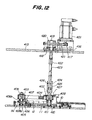
- Fig. 12 is a cross sectional view illustrating a detailed construction of the carrier driving unit.
- the sprocket 9a is secured to a shaft 409 which is rotatably supported by chain blocks 406 and 407 by means of bearings 408a and 408b.
- the pulley 403 is secured to the shaft 409.
- To a base 405 is journaled a shaft 411 via a bearing 410, and the pulley 402 is fixed to the shaft 411.
- the pulleys 402 and 403 are coupled with each other by means of the timing belt 404.
- a stationary plate 415 arranged horizontally is secured the servomotor 401 via a motor base 416 and a pulley 417 is secured to an output shaft of the motor 401.
- a shaft 419 is journaled to the stationary plate 415 via a bearing 418, and a pulley 420 is secured to the shaft 419.
- a timing belt 421 is arranged between the pulleys 417 and 420 there is arranged a timing belt 421.
- the shaft 419 is connected by means of a joint 422 to a connecting rod 423 which is coupled with the shaft 411 by means of a slide key 424.
- a connecting portion of the rod 423 and shaft 411 by means of the slide key 424 is covered with a coupling 425 which is fixed to the rod 423 by means of a screw 426.
- a shutter 427 is secured to the pulley 402 and the rotation of the shutter is detected by a photosensor 428 to derive a control signal for driving the servomotor 401.
- the carrier 12 is moved by one pitch.
- Fig. 13 illustrates the construction of the simple centering unit 300-2 for effecting the centering in the X direction.
- Figs. 13A, 13B and 13C are front, cross sectional and plan views, respectively.
- To the base 405 is secured a fitting member 450 to which a centering base 451 is directly secured.
- a pin cylinder 453 On a rear surface of the base 451 is arranged a pin cylinder 453 via a fitting 452, and a pair of flanges 454a and 454b are provided on a plunger 453a of the pin cylinder 453.
- On the surface of the centering base 451 are provided a pair of slider guides 455a and 455b, while these guides are connected to each other by means of a pushing plate 456.
- first slider 457 which is slidable between the slider guides 455a and 455b.
- a horizontal plate 458 To the first slider 457 is secured a horizontal plate 458 via a recess 451a formed in the centering base 451, said recess being extended vertically and being opened downward.
- a recess 458a formed in a tip of the horizontal plate 458 is engaged with the plunger 453a of pin cylinder 453 at a position between the flanges 454a and 454b.
- first slider 457 In the first slider 457 is formed a recess 457a extending vertically and being opened upward, and a second slider 460 is slidably inserted in the recess.
- a stopper pin 461 At the upper end of the second slider 460 is secured a stopper pin 461 which is made in contact with the pushing plate 456 to limit the downward movement of the second slider.
- a pin 462 At the lower end of the second slider 460 is secured a pin 462 to which a pair of claws 464 and 465 made of electrically conductive resin are journaled by means of colors 463.
- a pin 466 to which one ends of a pair of links 468 and 469 are journaled via colors 467. The other ends of the links 468 and 469 are journaled to the claws 464 and 465, respectively.
- a coiled spring 470 to bias these pins to move close to each other.
- Figs. 13A to 13C illustrate the condition in which the pin cylinder 453 has been energized so that tips of the claws 464 and 465 are brought into contact with each other.
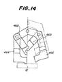
- Fig. 14 the claw 464 is illustrated to be fixed in such a position that it is brought into contact with the other claw 465.
- the first and second sliders 457 and 460 are in the upper portion, and due to the action of the spring 470 the lower end of the first slider 457 is urged against the lower end of the second slider 460.
- the pins 462 and 466 are close to each other and the claws 464 and 465 are in the position shown by a chain line in Fig. 14 and their tips are separated from each other.
- the chip device on the carrier 12 is clamped by the tips of claws 464 and 465 so that the chip device is moved into a correct position in the X direction It should be noted that the downward movement of the plunger 453a after the chip device has been clamped by the claws can be absorbed by the deformation of the spring 459.
- the simple centering unit 300-1 has the similar construction as that of the above mentioned simple centering unit 300-2 except for the point that the centering direction differs from that of the centering unit 300-2 by 90 degrees. Therefore, the detailed explanation of the simple centering unit 300-1 is dispensed with.
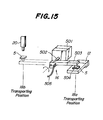
- Fig. 15 is a perspective view showing the turnover device 16 for turning over the chip device and transferring the chip device into the mounting head 20.
- the turnover device 16 comprises a pulse motor 501 and an arm 503 having one end coupled with an output shaft 502 of the motor. At the other end of the arm 503 is secured a suction nozzle 504.
- the nozzle 504 is connected to a vacuum source via a duct formed in the arm and a tube 505.
- the pulse motor 501 is energized to rotate the arm 503 in the clockwise direction until the nozzle 504 is brought into contact with the chip device, and then the chip device is sucked and held to the suction nozzle 504.
- the pulse motor 501 is driven in the reverse direction to rotate the arm in the counter clockwise direction by 180° into the second transporting position 18b. Therefore, the chip device is turned over and its upper surface faces upward. Then the mounting head 20 is moved downward and the chip device is transferred onto the lower end of the mounting head.
- the arm 503 is not moved linearly, but is rotated by 180°, the construction of the turnover device becomes very simple and the price of the device may be decreased materially. Further, the operation speed can be made very high.
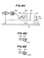
- Figs. 16A to 16E are plan, cross sectional, side and cross sectional views, respectively showing the detailed construction of the turnover device.
- the pulse motor 501 is secured to the base 415 via a bracket 506.
- a slit 507 which is optically detected by a photosensor 508 secured to the base 515.
- the photosensor 508 detects the origin of the arm 503 and the position of the arm is controlled in accordance with an output signal from the photosensor.
- the duct 503a is formed within the arm 503 and one end of the duct is communicated with the suction nozzle 504.
- a suction nozzle 504A shown in Fig. 16D has a flat end surface in which a small hole is formed and is advantageously used for sucking relatively small chip devices.
- a suction nozzle 504B illustrated in Fig. 16E comprises a ring and a tapered member having a large hole and is preferably used for sucking relatively large chip devices such as QFP.
- Fig. 17 is a perspective view showing the construction of the centering unit.
- the mounting head After the chip device 5 has been sucked onto the lower end of the mounting head 20 at the second transporting position 18b, the mounting head is slightly moved upward, and then is moved horizontally into the mounting position 18c. During the horizontal movement the mounting head 20 is temporarily stopped at a centering position 18d and is moved downward into the centering unit.
- the centering unit serves to adjust or correct the position of the chip device held at the lower end of the mounting head in the X and Y directions successively.
- a cylinder 551 for sliding a plate 512 in the X direction.
- the plate 512 has formed therein three leg portions 512a, 512b and 512c.
- outer leg portions 512a and 512b In inner edges of outer leg portions 512a and 512b are formed racks. An upright portion 513 is formed at a free end of the central leg portion 512c. A pair of pinion gears 514 and 515 are provided and are engaged with the racks of the.leg portions 512a and 512b, respectively. Between the pinion gears 514 and 515 is arranged a plate 516 slidably in the X direction and racks formed on both side edges are engaged with the pinion gears. At one end of the plate 516 is formed an upright portion 517. When the air cylinder 511 is energized, the plates 512 and 516 are moved in opposite directions along the X direction, so that the upright portions 513 and 517 are also moved closed to each other or away from each other.
- the centering unit in the Y direction is same as the above mentioned centering unit in the X direction and comprises air cylinder 521, plate 522 having three leg portions 522a-522c, a pair of pinion gears 524, 525 engaged with racks formed in inner side edges of the leg portions 522a and 522b, upright portion 523 formed at an end of the central leg portion 522c, plate 526 having racks engaged with the pinion gears and upright portion 527 formed at an end of the plate 526.
- the air cylinder 521 When the air cylinder 521 is energized, the plates 522 and 526 are moved in opposite directions along the Y direction and thus the upright portions 523 and 527 are moved close to each other or away from each other.
- the mounting head 20 is moved downward to such a level that that the chip device held at the tip of the mounting head with the aid of the suction force is positioned within a space surrounded by the upright portions 513, 517, 523 and 527.
- the air cylinder 511 is energized to move the upright portions close to each other until they are urged against the side edges of the chip device opposing to each other in the X direction.
- the air cylinder 511 is deenergized to move the upright portions 513 and 517 away from each other.
- the air cylinder 521 is energized to move the upright portions 523 and 527 close to each other until they are brought into contact with the side edges of the chip device opposing to each other in the Y direction.
- the air cylinder 521 is deenergized to move the upright portions 523 and 527 away from each other. In this manner, the centering can be effected in the X and Y directions, while the chip device is held positively on the tip of the mounting head with the aid of the suction force.
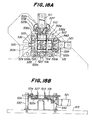
- Figs. 18A to 18E show the detailed construction of the centering unit.
- Figs. 18A, 18B, 18C and 18D, 18E are bottom, front, side and cross sectional views, respectively.
- an upper plate 531 is secured to the base 415 via posts 530.
- To the upper plate 531 are arranged rotatably four guide rollers 532a to 532d.
- Each of the guide rollers comprises two guide recesses each of which supports slidably each of the plates 512 and 522.
- the plates 516 and 526 are secured slidably to a rear surface of the upper plate 531 by means of pins 533 and 534 which are movable within elongated recesses formed in the upper plate.
- the pinion gears 514, 515 and 524, 525 are arranged rotatably between the upper plate 531 and elongated plates 535 and 536, respectively. As illustrated in Fig. 18D, each of the pinion gears 514 and 515 comprises two gear portions separated vertically from each other. The lower gear portions of pinion gears 514 and 515 are engaged with the racks formed in the inner side edges of the leg portions 512a and 512b of the plate 512, and the upper gear portions are engaged with the racks formed in the side edges of the plate 516. Between the plate 512 and the air cylinder 511 are arranged coiled springs 537 and 538, and between the plate 522 and the air cylinder 521 are provided coiled springs 539 and 540. By means of these coils, the upright portions 513, 517 and 523, 527 can be returned into the home positions quickly after effecting the centering.
- the chip device sucked at the tip of the mounting head 20 can be brought in position at a high speed. Further, the construction of the centering unit can be made very compact. It should be noted that the centering unit is used to position chip devices having small dimension, and large chip devices having large size such as QFP are positioned by the electric centering unit including the image signal processing circuit.
- Fig. 19 is a perspective view showing the basic construction of the mounting unit.
- the mounting head 20 is moved two dimensionally in the X and Z directions by means of ball screws.
- the mounting head 20 is secured to an arm 551 which is coupled with a ball screw 552 via a ball nut, said ball screw being extended in the Z direction.
- the ball screw 552 is supported by a slide plate 553 which is arranged slidably in the X direction.
- a pulley 554 At a top end of the ball screw 552 is arranged a pulley 554, and a timing belt 556 is provided between the pulley 554 and another pulley 555 which is coupled with an output shaft of a pulse motor 557.
- the slide plate 553 is coupled with a ball screw 558 extending in the X direction by means of a ball nut. One end of the ball screw 558 is connected to a servomotor 559.
- the slide plate 553 is slidably supported by a guide plate 560.
- the slide plate 553 is moved in the X direction and thus the mounting head 20 is also moved in the X direction via the arm 551.
- the pulse motor 557 is energized to rotate the ball screw 552
- the arm 551 is moved in the Z direction and therefore the mounting head 20 is moved vertically.
- the mechanism for moving the mounting head in the Z direction is mounted on the mechanism for driving the mounting head in the X direction, the movements in the X and Z directions can be carried out simultaneously, so that the high speed operation can be attained. Further, the positions of the mounting head in the X and Z directions can be set at will by controlling the motors 559 and 557, and therefore various functions can be easily added or altered and various timings can be set simply. Moreover, the mounting unit can be made very simple in construction and cheap in cost, and noise generated by the mounting unit can be decreased to a great extent.
- Figs. 20A and 20B are plan and front views, respectively illustrating the detailed construction of the mounting unit.
- the mounting head 20 is secured to one side edge of the arm 551.
- a box 561 is secured to the arm 551 and the mounting head is rotatably inserted in the box.
- a pulley 562 At an upper end of the mounting head 20 there is provided a pulley 562, and a timing belt 565 is arranged between the pulley 562 and a pulley 564 secured to an output shaft of a pulse motor 563 which is fixed to the arm 551.
- On the surface of the arm 551 there are arranged four guides 566a, 566b, 567a and 567b extending in the Z direction.
- the guides 566a, 566b and 567a, 567b there are clamped rails 568 and 569, respectively which are secured to the slide plate 553 so as to constitute a so-called linear way mechanism.
- the ball screw 552 is rotatably secured to the slide plate 553 by means of bearings 570 and 571.
- a ball nut 572 engaged with the ball screw 552 is secured to the arm 551. Therefore, when the pulse motor 557 is energized to rotate the ball screw 552, the arm 551 is moved in the Z direction via the ball nut 572.
- a shutter 573 is secured to the arm and photosensors 574a and 574b are secured to the slide plate 553.
- the ball screw 558 is rotatably supported by bearings 575 and 576 secured to the guide plate 560.
- the ball screw 558 is engaged with a ball nut 558 secured to the slide plate 553.
- To the guide plate 560 are fixed a pair of guide rails 578 and 579 which are engaged with sliders 580a, 580b and 581a, 581b, respectively secured to the slide plate 553.
- the ball screw 558 is coupled with the output shaft of the servomotor 559 via a coupling 582.
- To the servomotor 559 is connected a rotary encoder 583 for detecting an amount of rotation of the ball screw 558. In order to detect the position of the slide plate 553, i.e.
- a shutter 584 is secured to the slide plate, and photosensors 585a to 585e are arranged on the guide plate 560 at positions corresponding to the mounting position, decelerating position, nozzle exchange position, centering position and chip device transferring position.
- the output signal from the photosensor 585b for detecting the decelerating position is used to begin to decelerate the moving speed of the mounting head 20 toward the mounting position in the X direction at a suitable timing.
- the mounting head 20 is communicated with an air suction source via a tube 586.
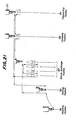
- Fig. 21 is a schematic view showing the positions of the mounting head 20 in the X and Z directions at respective operational positions.
- the mounting head 20 is moved downward and the chip device is sucked and held at the lower end of the mounting head. Then the mounting head is moved upward and is moved forward in the X direction into the centering position 18d. At the centering position, the mounting head 20 is moved downward and the chip device is inserted into the centering device. After the centering, the mounting head is moved upward and then is moved forward in the X direction into a waiting position 18e. At the waiting position 18e, the mounting head is moved downward.
- both the motors 557 and 559 are energized to move the mounting head along a curved path into the mounting position 18c.
- the mounting head is returned into the waiting position 18e also along the curved path.
- the mounting head is moved upward and then is moved backward in the X direction into a nozzle exchange position 18f.
- the suction nozzle When it is required to exchange the suction nozzle, the suction nozzle is first returned into a vacant nozzle receiving position by moving the mounting head up and down, and then after the mounting head is moved into a position above a desired suction nozzle, the mounting head is moved up and down to clamp the relevant suction nozzle into the tip of the mounting head. After the suction nozzle has been exchanged, the mounting head is moved upward and is then moved backward in the X direction into the initial position 18b.
- the mounting head 20 can be moved up and down precisely by means of the pulse motor 557, and therefore the lowermost position of the suction nozzle can be changed in accordance with the thickness of chip devices 5 as illustrated in Figs. 22A to 22C.
- the information about the thicknesses of chip devices may be previously entered together with the kinds of chip devices.
- Figs. 23A and 23B show the detailed construction of the mounting head and suction nozzle.
- Bearings 602 and 603 are arranged between the mounting head 20 and the box 561 which is secured to the arm 551 by means of pins 600 and 601.
- the mounting head 20 comprises outer sleeve 604 and inner sleeve 605 slidably inserted into the outer sleeve.
- inner sleeve 605 slidably inserted into the outer sleeve.
- an expanded portion 604a within which is arranged a coiled spring 606 so that the inner sleeve is biased downward.
- the inner sleeve 605 can be moved up and down with respect to the outer sleeve 604, but cannot be rotated with respect to the outer sleeve.
- a nip 609 In the tip end of the outer sleeve 604 is inserted a nip 609 to which is connected the tube 586 shown in Fig. 20B.
- a tapered hole 610 In the lower end of inner sleeve 605 there is formed a tapered hole 610 which is expanded downward.
- a ring-like recess 611 On an outer surface of the lower end of inner sleeve 605 there is formed a ring-like recess 611.
- Fig. 24 is a cross sectional view cut along a line A-A in Fig. 23A.
- three holes 611a ⁇ 611c In the bottom of the recess 611 there are formed three holes 611a ⁇ 611c which are communicated with the tapered hole 610 and are separated from each other in the circumferential direction by 120°.
- the suction nozzle 615 comprises a taper portion 615a corresponding to the tapered hole 610, a small diameter portion 615c formed between the lower end of the taper portion and a flange portion 615b, a nozzle tip portion 615d and a recess 615e formed in the outer surface of the taper portion 615a.
- Fig. 25 is a perspective view showing schematically the principal construction of the nozzle exchange device.
- an opera tion plate 620 is driven by an air cylinder 621 such that a front edge of the operation plate is projected into the thinned portion 615c of the suction nozzle 615, and then the mounting head 20 is moved upward to remove the suction nozzle from the mounting head due to the engagement of the plate 620 with the flange portion 615b.
- the suction nozzle may be secured to the mounting head by moving the head downward, while the operation plate 620 is clamped into the thinned portion 615c of the nozzle 615.
- Figs. 26A to 26E show the detailed construction of the nozzle exchange device.
- the nozzle exchange device comprises a base 630 to which a block 631 is secured by bolts 632a, 632b, the block having four nozzle containing holes 631a to 631d formed therein.
- On the block 631 is secured an upper plate 634 via a spacer 633.
- the upper plate 634 has formed therein an elongated hole 634a which surrounds all the nozzle containing holes 631a to 631d.
- an operation plate 635 having the construction shown in Fig. 26E is slidably arranged.
- the operation plate 635 In one edge of the operation plate 635, there are formed four semicircular recesses 635a to 635d each corresponding to respective nozzle containing holes 631a to 631d.
- the other edge of the operation plate 635 is connected via a coupling 636 to a driving shaft 637a of an air cylinder 637 including a returning spring.
- the cylinder 637 is supported by the base 630 by means of an L-shaped bracket 638.
- By driving the air cylinder 637 it is possible to extrude the operation plate 635 into the nozzle containing holes 631a to 631d of the block 631.
- any desired suction nozzle can be detachably secured to the mounting head.
- one mounting unit among the four mounting units can treat QFP.
- this mounting unit there is not provided the mechanical centering device shown in Fig. 17.
- the image information of QFP held by the mounting head is extracted and processed to detect the position and posture of QFP.
- An error in the position of QFP in the X and Y directions is compensated for by adjusting a position of the XY table supporting the printed circuit board, and an error in the posture is corrected by rotating the mounting head.
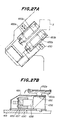
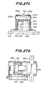
- Figs. 27A, 27B, 27C and 27D are plan view, longitudinal cross sectional view, lateral cross sectional view and bottom view, respectively illustrating the image information extracting unit.
- a base 650 on which is provided a housing 651.
- An upper surface of the housing 651 is partially opened, and above the opening there are arranged a pair of electroluminescent (EL) lamps 652a and 652b with the aid of fitting members 653a and 653b, respectively.
- EL lamps 652a and 652b are separated from each other to form an elongated space therebetween, through which the suction nozzle 615 holding QFP 654 can move horizontally.
- infrared cut filter 655 In the opening of the housing 651 there is clamped infrared cut filter 655 and below the filter there is arranged a prism 656 for bending an optical axis at right angles, the prism being secured onto the base 650.
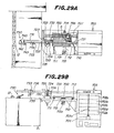
- Fig. 28 is a perspective view illustrating the QFP supply unit and Figs. 29A and 29B are plan and side views, respectively showing the QFP supply unit.
- a number of QFPs 5 are arranged in matrix on trays 700.
- QFPs 5 may be contained in a small tray 700 and the tray may be arranged on a pallet 701 having the same configuration as the usual tray 700. In such a case, various kinds of trays may be used.
- Ten trays 700 or pallets 701 containing QFPs of the same kind are detachably arranged in a stocker 702 as shown in Fig. 31. In inner surfaces of side walls of the stocker 702 are formed recesses for receiving the trays.
- the lift device 703 comprises a pair of guide rods 703a,703b, screw 703c, nut 703d and induction motor 704 coupled with the screw 703c. By energizing the induction motor 704, the stockers 702a ⁇ 702e can be moved up and down through a tray supply position.
- a tray feeding device In order to remove a tray 700 or pallet 701 indexed at the tray supply position by the lift device 703, there is provided a tray feeding device.
- the try feeding device comprises guide rod 705 extending horizontally in the X direction, air cylinder 706 arranged in parallel with the guide rod, hook 707 which may be engaged with a lag 701a provided at a front edge of a tray or pallet, and actuator 708 for moving the hook horizontally, the actuator being coupled with a plunger of the air cylinder 706 and being guided by the guide rod 705 movably in the X direction.
- the hook 707 and actuator 708 By driving the air cylinder 706, the hook 707 and actuator 708 are moved into the lift device 703.
- the actuator 708 is driven to project the hook 707 into the lag 701a of tray 700 or pallet 701. Then the air cylinder 706 is driven again to move the hook 707 together with the tray or pallet into the original position. Finally, the actuator 708 is driven to disengage the hook 707 from the lag 701a. Then the tray 701 can be freely moved without being interrupted by the hook. In this manner, a given tray or pallet is removed from the lift device 703 and is indexed into a given position on an Y table 712 placed on guides 710, 711 extending in a Y direction perpendicular to the X direction. The Y table 712 is secured to an endless belt 715 provided between pulleys 713 and 714. Therefore, by rotating the belt 715 by means of a motor 715a, the Y table 712 can be moved in the Y direction along the guides 710, 711.
- first feeding device for feeding QFP 5 contained in the tray 700 or pallet 701 into a simple centering device 720.
- This first feeding device comprises endless belt 721 and guide rod 722 both extending in the X direction, pulse motor 723 for rotating the endless belt 721, frame 724 secured to the belt 721 and slidably supported by the guide rod 722,arm 725 secured to the frame 724 movably up and down and suction nozzle 726 provided at a lower end of the arm 725.
- pulse motor 723 When the pulse motor 723 is energized to rotate the endless belt 721, the frame 724 is moved in the X direction such that the suction nozzle 726 comes into a position just above a desired QFP 5 to be supplied.
- the arm 725 is moved downward and the QFP is sucked onto the nozzle 726. Then after the arm 725 has been moved upward, the pulse motor 723 is energized again to feed the QFP 5 into a position above the simple centering device 720. Next, the arm 725 is moved downward and the suction force is weakened to place the QFP 5 on the simple centering device.
- the simple centering device 720 effects the centering of QFP 5 in the X and Y directions as will be explained later. Then the QFP 5 is transferred from the simple centering device 720 to a turnover device 730. This transferring is carried out by a second X direction feeding device.
- the second feeding device comprises endless belt 731 extending in the X direction, pulse motor 732 for rotating the endless belt 731, frame 733 secured to the endless belt 731 and being slidably supported by the guide rod 722, arm 734 secured to the frame 733 movably up and down, and suction nozzle 735 secured to the tip of the arm 734.
- the operation of the second feeding device is identical with that of the first feeding device, so that its explanation is omitted.
- the QFP 5 sucked onto the suction nozzle 735 of the second feeding device is fed into a position above the turnover device 730. Then, the arm 734 is moved downward and the QFP 5 is transferred to the suction nozzle provided at a tip of arm of the turnover device.
- Fig. 32 illustrates the construction of the turnover device 730.
- the turnover device 730 comprises stand 740, motor 741 provided on the stand, arm 742 secured to an output shaft of the motor 741, and suction nozzle 743 provided at a free end of the arm.
- the QFP supply unit has to be placed at any desired position on the mounting unit, and thus a permanent magnet is provided on the stand 740 and a table 745 of the mounting unit is made of magnetic material such as iron.
- the arm 742 is rotated by 180° to transfer the QFP onto a carrier 12. On the carrier 12, the QFP 5 is held in the upside down fashion.
- the table 712 is returned into the origin and then the tray is returned into the lift device 703 by means of the X direction feeding device. Then, the motor 704 is energized to feed a given tray 700 or pallet 701 into the supply position. In this manner, desired QFPs can be successively supplied.
- Figs. 32A to 32D show the construction of the simple centering unit for QFP.
- the centering unit comprises a cylindrical main body 750 and an inner sleeve 751 arranged slidably within the main body.
- the lower end of inner sleeve 751 is connected to a cylinder 752.
- a weight color 753 is inserted, and arms 754a to 754d are secured to the upper end of weight color, the arms extending in mutually orthogonal directions to form a cross.
- free ends of each arms 754a to 754d are formed recesses in which one ends of L-shaped links 755a to 755d are inserted.
- the links 755a to 755d are journaled by pins 756a to 756d, respectively secured to the main body 750.
- the ends of the links 755a to 755d inserted in the recesses of arms 754a to 754d there are formed recesses through which pins 757a to 757d, respectively are passed.
- On an upper surface of main body 750 there is integrally formed posts 760 by means of which an intermediate plate 761 and upper plate 762 are supported. These plates 761 and 762 constitute a guide for supporting four slide plates 763a to 763d slidably in the radial direction.
- the slide plates 763a to 763d there are secured pins 764a to 764d which are inserted into recesses formed in the other ends of links 755a to 755d.
- the cylinder 752 is energized, so that the inner sleeve 751 is in the upper position and the slide plates 763a to 763d are retarded outwardly.
- the cylinder 754 is deenergized to move the inner sleeve 751 and weight color 753 downward due to the gravitational force.
- the links 755a to 755d are rotated and the slide plates 763a to 763d are simultaneously moved toward the center of the opening 762a.
- the slide plates 763a to 763d are brought into contact with the QFP 5 to effect the centering.
- the inner sleeve 751 and weight color 753 are moved upward by actuating the air cylinder 752 to move the slide plates 763a to 763d outwardly. In this manner, in the present embodiment, the centering can be performed simultaneously both in the X and Y directions.
- the present invention is not limited to the embodiments explained above, but many modifications and alternations may be conceived by those skilled in the art within the scope of the invention.
- the carriers are secured to the chain, but they may be connected to other driving members such as timing belt. Further, it is not always necessary to rotate the mounting head at any desired angle, but it may be indexed into three angular positions, i.e. 0° and ⁇ 45°.
- the automatic chip mounter desired chip devices provided in a number of tape units are supplied in a predetermined order onto carriers in the upside down fashion and are held on the carriers with the aid of the suction force. Then the chip devices are successivesively fed into the transporting position to the turnover device which holds the chip device and turns over the chip device. Then the turned over chip device, i.e. correctly oriented chip device is transferred to the mounting head. At the same time, the printed circuit board arranged on the XY table is indexed with respect to the mounting position. Then the mounting head is moved downward to mount the chip device on the circuit board. In this manner, the chip devices can be mounted on the circuit board in a prompt and positive manner, while the tape unit mounting unit, feeding unit, turnover unit and mounting head can be made simple and small.
- the chip device can be positively held on the carrier, because the chip device is placed on the carrier in the upside down fashion. Further, during the transportation the chip device is hardly deviated on or dropped from the carrier.
Abstract
Description
- The present invention relates to an apparatus for mounting automatically various kinds of chip devices on a printed circuit board.
- Such an apparatus is generally called "Chip Mounter" and has been used for mounting active chip devices such as chip IC, chip transistor and chip diode as well as passive chip devices such as chip resistor, chip capacitor and chip coil.
- Various kinds of chip mounters have been developed. Usually a number of chip devices of the same kind are arranged in a tape which is wound as a coil. In a known chip mounter, a plurality of tape coils are set on a plurality of tape units arranged side by side and these tape units are moved with respect to a mounting head. After a tape unit on which a tape coil having desired chip devices has been indexed into the mounting head, one chip device is supplied from the tape unit to the mounting head. Then the mounting head is indexed at a given position on a printed circuit board placed on an XY table and the chip device is mounted on the printed circuit board.
- In such an apparatus the chip device to be mounted is held at a lower end of the mounting head with the aid of the suction force, and therefore the number of different kinds of chip devices which can be mounted by the single mounting head could not be made large. Therefore, there has been also proposed a chip mounter in which a plurality of mounting units each being composed of tape unit, mounting head and XY table are arranged in series with each other and a printed circuit board is transported through successive mounting units, while desired chip devices are mounted on the circuit board in respective mounting units.
- There is further proposed a chip mounter including a plurality of mounting heads each holding chip devices having different sizes and shapes and a desired mounting head is selectively used in accordance with a chip device to be mounted.
- In the known chip mounter in which a number of tape units are moved with respect to the single mounting head, it is required to provide a large scale driving mechanism for moving the heavy and long tape unit assembly in a reciprocal manner. It is apparent that such a mechanism could not move the tape unit assembly at a high speed, and thus the mounting rate is limited. Particularly, when it is required to mount many different kinds of chip devices, the weight and length of the tape unit assembly become large and the mounting rate would be further decreased. Moreover, the range over which the tape unit assembly is moved is quite long, so that a space factor of the chip mounter is very small.
- In the known chip mounter in which a plurality of mounting units are arranged side by side and a printed circuit board is traveled through these mounting units, the whole apparatus is liable to be very large and becomes very expensive. Further, there is additionally required mechanisms for moving the printed circuit board between successive mounting units. Therefore, the mounting rate is also limited.
- In the known chip mounter in which a plurality of mounting heads are selectively used, the apparatus may be made rather small, but the construction of the mounting head assembly becomes quite complicated and the mounting rate becomes low, because the changing of mounting heads requires a relatively long time.
- The present invention has for its object to provide an apparatus for mounting automatically different kinds of chip devices on a printed circuit board at a high speed, while the whole apparatus can be made small in size, simple in construction and cheap in cost.
- According to the invention, an apparatus for mounting automatically chip devices on a printed circuit board comprises
supplying means for supplying chip devices one by one in an upside down fashion in a predetermined order;
chip device feeding means for receiving and holding the chip devices supplied from the chip device supplying means with the aid of the suction force, while the chip devices are held in the upside down fashion, and feeding the chip devices thus held into a first transporting position;
turning over means for receiving the chip device indexed at the first transporting position with the aid of the suction force, turning over the chip device thus held and transporting the chip device into a second transporting position; and
mounting means for receiving the chip device indexed at the second transporting position with the aid of the suction force, transporting the chip device thus held on a printed circuit board at a predetermined position thereof and placing the chip device on the printed circuit board. - The invention will now be described in detail with reference to the accompanying drawings, in which:
- Fig. 1 is a schematic plan view showing a principal construction of an embodiment of the automatic chip mounter according to the invention;
- Fig. 2 is a perspective view depicting a tape unit;
- Figs. 3A and 3B are plan and side views, respectively illustrating the chip device supplying and feed units;
- Figs. 4A to 4D show the construction of the tape unit mounting unit;
- Fig. 5 is a perspective view of the tape unit driving unit;
- Figs. 6 and 7 are front and side views illustrating the detailed construction of the tape unit driving device;
- Fig. 8 is a side view showing the one-shot unit;
- Figs. 9A and 9B are plan and cross sectional views representing the carrier;
- Figs. 10A and 10B are plan and cross sectional views, respectively showing the assembly of the carriers and chain;
- Fig. 11 is a perspective view illustrating the chain driving unit;
- Fig. 12 is a cross sectional view illustrating the detailed construction of the chain driving device;
- Figs. 13A to 13C and 14 show the simple centering unit;
- Fig. 15 is a perspective view depicting schematically the detailed construction of the simple centering unit;
- Figs. 16A to 16E show the detailed construction of the simple centering unit;
- Fig. 17 is a perspective view showing schematically the centering unit;
- Figs. 18A to 18E illustrate the detailed construction of the centering unit;
- Fig. 19 is a perspective view depicting the principal construction of the mounting unit;
- Figs. 20A and 20B are plan and side views, respectively showing the detailed construction of the mounting unit;
- Fig. 21 is a schematic view illustrating the moving path of the mounting head;
- Figs. 22A to 22C are side views showing the relation between thicknesses of chip devices and descending heights of the mounting head;
- Figs. 23A and 23B are cross sectional and perspective views, respectively showing the construction of the mounting head and suction nozzle;
- Fig. 24 is a cross sectional view cut along line A-A in Fig. 23A;
- Fig. 25 is a perspective view schematically showing the nozzle exchange device;
- Figs. 26A to 26E illustrate the detailed construction of the nozzle exchange device;
- Figs. 27A to 27D depict the construction of the image information extracting device;
- Fig. 28 is a perspective view showing the QFP supply unit;
- Figs. 29A and 29B are plan and front views, respectively illustrating the QFP supply unit;
- Figs. 30 and 31 are perspective views depicting the QFP pallet and stocker, respectively; and
- Figs. 32A to 32D show the QFP centering device.
- Fig. 1 is a schematic view showing schematically the basic construction of an embodiment of the chip mounter according to the invention. A tape
unit mounting unit 1 comprises a plurality of tape units 2-1∼2-n arranged side by side in a horizontal direction at a constant pitch. In each tape unit there is arranged a tape containing a number of chip devices. - As illustrated in Fig. 2, a
tape 3 comprises a containingtape 3a having a number ofdepressions 4 formed therein at a constant pitch in the longitudinal direction, and acover tape 3b which is adhered onto the containingtape 3a in a removable manner.Chip devices 5 of the same kind are provided inrespective depressions 4 and thetape 3 is wound on a real 6. In the containingtape 3a there are formedholes 3c along one side thereof at positions betweensuccessive depressions 4. - In Fig. 1, different kinds of tapes may be provided in respective tape units 2-1∼2-n or a plurality of chip devices of the same kind may be provided in a plurality of tape units, if chip devices of the relevant kind are frequently used.
- The
tape 3 provided in thetape unit 2 is selectively fed in a stepwise manner, while thecover tape 3b is peeled out of the containingtape 3a. In this manner, a chip device can be fed into afeeding unit 8 one by one. - The
feeding unit 8 comprises a pair ofsprockets endless chain 10 provided around the sprockets,suction chamber 11 arranged along the chain and a number ofcarriers 12 which are secured to the chain in such a manner that the carriers are sled on the suction chamber. Thecarriers 12 are arranged at the same pitch as that of the tape units 2-1∼ 2-n. In a top surface of thesuction chamber 11 there are formed a number of suction holes lla along the longitudinal direction thereof. Thesuction chamber 11 is coupled with asuction pump 13 so that the space inside the chamber is maintained at a negative pressure of, for example, -100 mmHg and air is sucked within the chamber via the holes 11a. It should be noted that the negative pressure within thechamber 11 may be set to a value within a range of -60∼-200 mmHg. The suction holes 11a are formed at such a pitch that thecarrier 12 can always cover at least one suction hole. In a rear surface of thecarrier 12 there is formed a suction buffer which is communicated with suction openings 12a. Therefore, thesuction pump 13 sucks the air through suction openings 12a, suction buffer, suction hole 11a andchamber 11. - The
chain 10 is rotated as shown by an arrow A in a stepwise manner by means of amotor 14 coupled with thesprocket 9a such thatsuccessive carriers 12 are indexed with respect to successive tape units 2-1 to 2-n. When achip device 5 is fed on acarrier 12 in the upside down fashion, the chip device is held on the carrier with the aid of the suction force, because the chip device clogs the suction openings 12a. - The chip device held on the
carrier 12 is transported into a turn overunit 15 including aturnover device 16 which is coupled with asuction pump 17. At first, theturnover device 16 sucks the chip device held on thecarrier 12 positioned at a first transportingposition 18a with a suction force which is higher than the suction force by means of which the carrier retains the chip device. This former suction force may be set to a value within a range of -300∼-500 mmHg. Therefore, the chip device is transferred from thecarrier 12 into the turnover device. 16. Then, the turnover device turns over the chip device by 180° about an axis extending horizontally. Therefore, the top surface of the chip device faces upward. Then, the chip device is fed into a second transportingposition 18b. At this second transporting position, the chip device is transferred from the turnover device into a mountingunit 19. - The mounting
unit 19 comprises a mountinghead 20 which holds the chip device at its lower end with the aid of the suction force and places the chip device thus held on a printedcircuit board 22 mounted on an XY table 21. The mountinghead 20 is moved by a mountinghead driving device 23 horizontally between the second transportingposition 18b and a mountingposition 18c as well as vertically atrespective positions head 20 is rotated about a vertical axis. In order to hold the chip device onto a tip of the mountinghead 20, the mounting head is coupled with asuction pump 24 which generates a negative pressure of -300∼-500 mmHg. In case of transporting the chip device from the turn overunit 15 to the mountinghead 20, the suction force of the turn overunit 15 is stopped or decreased, and further after the chip device has been placed on the printedcircuit board 22, the suction force of the mounting head is stopped or reduced. In the present embodiment, after a given position of the printedcircuit board 22 is indexed into the mountingposition 18c by moving the XY table 21 by means of an XYtable driving device 25, a syringe containing an adhesive agent is moved downward and a given amount of adhesive agent is applied on a given position of the printed circuit board by actuating the syringe. Then, the mountinghead 20 is moved downward and the chip device held at its tip is placed on the printed circuit board at the position on which the adhesive agent has been applied. In this manner, the chip device can be mounted and fixed on the printed circuit board. The tape units 2-1 to 2-n,chain driving motor 14, suction pumps 17 and 24,head driving device 23 and XYtable driving device 25 are controlled by acontrol unit 26. - Prior to effect the actual mounting, it is necessary to determine which chip devices are mounted at which positions on the printed circuit board. This may be effected by the profiling mode or by the programming mode. In the profiling mode, at first the mounting head is indexed manually at a given position on the printed circuit board and then a kind of chip device to be mounted at the relevant position is entered by operating a key board. In the present embodiment, the profiling mode is adopted.
- Figs. 3A and 3B are plan and front views, respectively showing a general construction of the chip mounter of the present embodiment. In the present embodiment, there are provided four mounting heads by means of which chip devices are mounted on the printed circuit board at the single
common mounting position 18c. Four mounting devices each including respective mounting heads are arranged substantially symmetrically with respect to thecommon mounting position 18c. The construction of these mounting devices is same, so that in Figs. 3A and 3B the construction of a single mounting device is illustrated. The mounting unit comprises tapeunit mounting unit 1, feedingunit 8, turning overunit 15 and mountingunit 19. In this embodiment, carries 12 in each feedingunits 8 are driven independently from each other by means of separate driving devices, and further in order to transfer a chip device held on thecarrier 12 to aturnover device 16 of the turning overunit 15 at a transportingposition 18a in a positive manner, there are provided two centering devices 300-1 and 300-2 having a simple construction by means of which the chip device held on the carrier is clamped in X direction parallel to the feeding direction as well as Y direction perpendicular to the X direction. In the mountingunit 19 there are arranged centeringdevice 301 and suctionnozzle exchanging device 302 between the second transportingposition 18b and the mountingposition 18c. By means of the centeringdevice 301 the position of a chip device sucked at the tip of suction nozzle secured to the lower end of the mountinghead 20 is corrected in the X and Y directions. By means of the nozzle exchanging device 302 a desired suction nozzle is selectively secured to the mountinghead 20 in accordance with shape and size of chip devices to be mounted. - The remaining mounting devices have the same construction as that mentioned above, but a mounting device for mounting special chip devices such as QFP (Quad Flat Package) which includes a number of lead wires extending substantially horizontally from side walls does not comprise the mechanical centering devices 300-1 and 300-2, but includes an electrical centering device comprising an image pick-up device and an image signal processing device.
- Now detailed construction of respective units will be explained.
- The tape
unit mounting unit 1 operates to drive selectively a plurality of tape units 2-1∼2-n which are arranged along the moving path of thecarriers 12 at a constant pitch by driving a tapeunit driving device 303 and a chip device contained in a tape is supplied onto acarrier 12 of thefeeding unit 8 in a turn over fashion. That is to say, on thecarrier 12 the rear surface of chip device faces upward. - Figs. 4A and 4B are front and side views, respectively illustrating the
tape unit 2. To abase 305 is rotatably secured thereel 6 on which thetape 3 is wound. Thetape 3 is guided out of thereel 6 viarollers transferring base 308 provided at a lower portion of thebase 305 for defining a level of the chip device transferring path in such a manner that thecover tape 3b faces downward. In the transferringbase 308 there is formed arecess 308b for supplying a chip device via aslide surface 308a. At the position ofslide surface 308a andrecess 308b thetape 3 is pressed downward by means of atape pusher 309. Thetape pusher 309 is journaled by ashaft 310 and is biased by a coiled spring 311 such that thetape 3 is urged against theslide surface 308a. - The
cover tape 3b oftape 3 is turned at therecess 308b, so that achip device 5 contained in adepression 4 of the containingtape 3a is dropped onto acarrier 12 via therecess 308b, while thecover tape 3b is peeled off the containingtape 3a. In order to supply positively thechip device 5 onto thecarrier 12, theslide surface 308a formed in the transferringbase 308 is thinned toward therecess 308b. - The
cover tape 3b peeled off thetape 3 at the transferringbase 308 is wound on a take-upreel 312 viarollers reel 312 is secured to areel bracket 313 which is arranged rotatably about a shaft 313a secured to thebase 305. Thereel bracket 313 comprises aspring pin 313b which is engaged with the take-upreel 312, and an O-ring 313c which is made in contact with the take-up reel. In a periphery of thereel bracket 313 there is formed agear 313d which is engaged with aratchet 314a provided on the base 305 so that thereel bracket 313 can rotate only in the clockwise direction in Fig. 4A, i.e. in a direction for taking up thecover tape 3b. Between thebase 305 and thereel bracket 313 there is arranged afeed plate 315 via aflat washer 315a, the feed plate being rotatable about the shaft 313a. On thefeed plate 315 there is provided aratchet 314b which is engaged with thegear 313d of thereel bracket 313. Therefore, thereel bracket 313, i.e. the take-upreel 312 can rotate in the clockwise direction with the aid of theratchet 314b only when thefeed plate 315 is rotated in the clockwise direction in Fig. 4A. In the present embodiment, thefeed plate 315 can be selectively rotated by means of the tapeunit driving device 303 as will be explained later. - After the
chip device 5 provided in thedepression 4 of thetape 3 has been supplied onto thecarrier 12, the containingtape 3a is fed in the leftward in Fig. 4A by means ofsprocket 316 andtape guide 307b. Thesprocket 316 serves to feed thetape 3 in a stepwise manner. The containingtape 3a is urged against thesprocket 316 by atape pusher 317 and agear 316a of the sprocket is inserted into thehole 3c. Thetape pusher 317 is biased by acoiled spring 318 to be urged against the containingtape 3a. With the feedingsprocket 316 is coupled asprocket ring 319 via a one-way clutch and the sprocket ring is selectively rotated by the tapeunit driving device 303 as will be explained later. Then thetape 3 is fed by one pitch and thecover tape 3b is peeled off the containingtape 3a at the transferringbase 308 and thechip device 5 is supplied onto thecarrier 12 as shown in Fig. 4D. As illustrated in Fig. 4C, apositioning stopper 320 provided on thebracket 305 is urged against the feedingsprocket 316. - In order to rotate the take up
reel 312 and feedingsprocket 316 by means of the tapeunit driving device 303, alink 321 is provided on the base 305 rotatable about a shaft 321a. One end of thelink 321 is rotated in the clockwise direction in Fig. 4A by means of the tapeunit driving device 303. To the other end of thelink 321 there are secured one ends oflinks 322 and 323 rotatably, and the other end of the link 322 is engaged with thefeed plate 315 by means ofpin 322a andrecess 315a. The other end of thelink 323 is engaged with thesprocket ring 319 via a pin 323a. Thelink 321 is biased by acoiled spring 324 to rotate in the counter clockwise direction in Fig. 4A. Thefeed plate 315 is biased by acoiled spring 325 to rotate in the clockwise direction in Fig. 4A, thespring 325 being weaker than thespring 324. Therefore, in the normal condition of thelink 321 shown by a solid line in Fig. 4A, the take-upreel 312 is biased by thespring 325 to rotate in the clockwise direction, so that thecover tape 3b is subjected to the tension applied to the take-upreel 312. - When the
link 321 is rotated in the clockwise direction by means of the tapeunit driving device 303, thefeed sprocket 316 is rotated in the clockwise direction via thelink 323 andsprocket ring 319 and thetape 3 is fed by one pitch. Then after a short delay time due to the difference in the spring force between thesprings feed plate 315 is rotated in the clockwise direction via the link 322. Therefore, thereel bracket 313 and take upreel 312 are rotated in the clockwise direction by means of theratchet 314b, and thecover tape 3b is wound on the take-upreel 312 by one pitch. Then, thechip device 5 stored in thetape 3 is supplied through therecess 308b of the transferringbase 308 on thecarrier 12 in the upside down fashion. When thelink 321 is returned into the original position, only thesprocket ring 319 is rotated in the counter clockwise direction. Further, since the rotation of thereel bracket 313 in the counter clockwise direction is inhibited by theratchet 314a, only thefeed plate 315 and ratchet 314b are rotated in the counter clockwise direction. - In order to detect that the
tape 6 has been wholly rewound from thereel 6, ashutter plate 326 is journaled to theroller 306b and an engagingmember 326a is secured to the shutter plate at such a position that themember 326a is engaged with a portion of thetape 3 between therollers tape 3 has been wholly supplied from thereel 6, theshutter plate 326 is rotated in the counter clockwise direction due to the force of gravity until it is engaged with astopper 327 secured to thebase 305. When theshutter plate 326 is engaged with the stopper, a detection light path is interrupted by the shutter plate. The detection light path is defined by light emitting element and light receiving element. When the light receiving element detects the interruption of the detection light path, there is generated an alarm. - In order to provide the
tape unit 2 onto the tapeunit mounting unit 1 in a removable manner, aguide base 329 is provided on the base 305 with the aid of ashaft 328 at a lower portion of the base which is opposite to the portion at which thetransferring base 308 is provided. To one end of theguide base 329 there are journaledclamp lever 330 and clamplock 331. The other end of theguide base 329 is engaged with aguide 333a secured to a base 322 of the tapeunit mounting unit 1. By rotating theclamp lever 330 in the clockwise direction to engage theclamp lock 331 with anengaging plate 333b secured to thebase 332, thetape unit 2 may be detachably secured to the tapeunit mounting unit 1. Between theclamp lever 330 and clamplock 331 is arranged acoiled spring 334,so that when theclamp lever 330 is rotated in the counter clockwise direction, theclamp lock 331 is rotated in the counter clockwise direction due to the force of thespring 334 and is disengaged from theengaging plate 333b. Between theguide base 329 and thebase 305 is arranged acoiled spring 335 for biasing the base 305 to rotate in the counter clockwise direction about ashaft 328. Therefore, when the tapeunit driving device 303 is in the non-operating condition, therecess 308b of thetransferrring base 308 is sufficiently spaced from the carrier traveling path so that thecarriers 12 can be moved smoothly. The rotation of thebase 305 is limited by the engagement of an engagingmember 336 secured to the base 305 with astopper 337 secured to theguide base 329. In the manner explained above, before supplying thechip device 5 onto thecarrier 12, thebase 305 is rotated in the clockwise direction against the force of thespring 335 in conjunction with the rotation of thelink 321 due to the operation of the tapeunit driving device 303 and therecess 308b of the transferringbase 308 is moved closer to thecarrier 12. Then thelink 321 is further rotated to supply thechip device 5 onto thecarrier 12. - Fig. 5 is a perspective view showing a principal construction of the tape
unit driving device 303. The tapeunit driving device 303 comprises a pushingplate 350 which extends in the direction in which thetape units 2 are arranged side by side. The pushingplate 350 is rotatably supported by shafts 351a and 351b at its both ends and is rotated byair cylinders shot units 353 are provided in accordance withrespective tape units 2 arranged in the tapeunit mounting unit 1. The one-shot unit 353 comprises aselection arm 354 which is slidably engaged with the lower end of the pushingplate 350 by means of apin 355. When theselection arm 354 is remained in a rest position, even when the pushingplate 350 is rotated downward, the selection arm is not brought into contact with thelink 321. On the other hand, when theselection arm 354 is protruded by operating the one-shot unit 353, the pushingplate 350 is urged against thelink 321 of acorresponding tape unit 2 to rotate the link in the clockwise direction. - Figs. 6 and 7 are front and side views illustrating the tape
unit driving unit 303. In Fig. 7, the left-hand driving device is shown as a cross sectional view. The pushingplate 350 is biased by acoiled spring 356 to rotate downward and theselection arms 354 for respective one-shot units 353 are slidably hung from the pushing plate via thepins 355. In Fig. 7, the pushingplate 350 in the left-hand driving device 303 is in a normal position, while the pushing plate in the right-hand driving device is in the descendant position. - Fig. 8 is a side view of the one-
shot unit 353. The one-shot unit 353 comprises abase 360 and alever 362 journaled to ashaft 361 secured to thebase 360. One end of theselection arm 354 is journaled to one end of thelever 362. To the one end of thelever 362 is connected acoiled spring 363 to bias the lever to rotate in the counter clockwise direction in Fig. 8. This rotational movement is limited by astopper 364. Asolenoid 365 is secured to thebase 360 and aplunger 365a of solenoid is coupled with thelever 362 at a position between the fitting positions to theshaft 361 andselection arm 354, respectively. When thesolenoid 365 is energized, thelever 362 is rotated in the counter clockwise direction against the force of thespring 363 so that thelink 321 is rotated via the engagement of the selection arm with the link. Theselection arm 354 is hung from the pushingplate 350 by means of thepin 355. That is to say, one end of thepin 355 is secured to the lower edge of the pushingplate 350 and the other end of the pin is inserted into an elongated hole formed in an upper surface of theselection arm 354. - A
guide pin 366 is secured to theselection arm 354 and is engaged with adog 367 formed in thebase 360. When thesolenoid 365 is energized, and theselection arm 354 is moved into the selecting position, the selection arm is remained in this position. Further, when the pushingplate 350 is moved downward, theguide pin 366 is moved along thedog 367. - When the
solenoid 365 is energized, thelever 362 is rotated in the counter clockwise direction against thecoiled spring 363, so that theselection arm 354 is moved into the selecting position. In this selecting position, theguide pin 366 has passed over amountain portion 367a of thedog 367 and has been engaged with anupright portion 367b. In this position, theselection arm 354 is remained in the selecting position even when thesolenoid 365 is deenergized. When theselection arm 354 is rotated downward in conjunction with the rotation of the pushingplate 350, theguide pin 366 is moved downward along theupright portion 367b ofdog 367. By means of this rotational movement of the selection arm 354 a chip device is supplied from atape 3 onto acarrier 12. Near the stop position of the downward movement of the pushingplate 350, theselection arm 354 is disengaged from thelink 321 due to the action of thespring 363 and theguide pin 366 passes through avalley portion 367c of thedog 367. Thereafter, theguide pin 366 is moved upward along anupright portion 367c opposite to theupright portion 367b in accordance with the upward movement of the pushingplate 350 and is returned into a home position. Therefore, in the selection mode, theguide pin 366 turns around thedog 367 by one revolution. It should be noted that when a tape unit is not selected, thelever 362 is in such a position that it is urged against thestopper 364. In this condition, theguide pin 366 is moved along theupright portion 367d and theselection arm 354 is not brought into contact with thelink 321 of the relevant tape unit. - As explained above, in the one-
shot unit 353 of this embodiment, theselection arm 354 can be remained in the selecting position by energizing thesolenoid 365 for a short time, and thus the power consumption can be saved. - The
feeding unit 8 comprises anendless chain 10, a number ofcarriers 12 secured to the chain and asuction chamber 11. While thecarriers 12 are fed on thesuction chamber 11, one ormore chip devices 5 are supplied on one ormore carriers 12 from the tapeunit mounting unit 1 and the chip device thus supplied is fed through the transportingposition 18a to theturnover device 16. As explained above, in three feeding units except for that for feeding chip devices such as QFP there are provided the simple centering devices 300-1 and 300-2 for centering the chip devices in the X and Y directions, respectively. - In this embodiment, the
carriers 12 of each mounting units have the substantially same construction. - Fig. 9A is a plan view showing the
carrier 12 and Fig. 9B is a cross sectional view cut along a line I-I in Fig. 9A. Thecarrier 12 is formed by a mold of electrically conductive resin. In a side of thecarrier 12 there are formedholes chain 10. In a rear surface of the carrier there is formed abuffer 371 which maintains the negative pressure within thesuction chamber 11. In an upper surface of thecarrier 12 there are formed fivesmall holes 372 at a central area thereof and eightlarge holes 373 in a symmetrical manner. Thesmall hole 372 has a diameter of 0.3 mm at the upper surface and of 0.6 mm at the lower surface, and thelarge hole 373 has a diameter of 0.5 mm at the upper surface and of 1.0 mm at the lower surface. That is to say, theseholes - Since the
carrier 12 is made of a conductive resin, undesired electrostatic charge can be effectively prevented. Further, thecarrier 12 can be manufactured in an easy and less expensive manner by the mold. Moreover, since the small andlarge holes - As illustrated in Figs. 10A and 10B, the
carrier 12 is secured to thechain 10 by means of fittingmember 375,colors 376 andbolts - The
suction chamber 11 has a cross section of 12 mm × 12 mm, and in an upper surface there are formed suction holes 11a having a diameter of 1.0 mm at a constant pitch. It should be noted that the pitches of the suction holes 11a andcarriers 12 and a length of thebuffer 371 formed in the rear surface of the carrier are so determined that at least one suction hole is always communicated with the buffers of the carriers so that the air is always sucked through the suction holes 372 and 373 formed in thecarrier 12. Thechamber 11 is coupled with the suction pump 13 (see Fig. 11) so that the pressure within thebuffer 371 is maintained at a given negative pressure within -60 to -200 mmHg. - Fig. 11 is a perspective view showing a principal construction of the carrier driving unit. In this embodiment, the
endless chain 10 extended between thesprockets independent driving unit 400. The drivingunit 400 comprises aservomotor 401 for rotating apulley 402 which is coupled via atiming belt 404 with apulley 403 coaxially secured to thesprocket 9a. In this manner, thechain 10 can be rotated by themotor 401 by means of thepulley 402,timing belt 404,pulley 403 andsprocket 9a. - In the manner explained above, since the
chains 10 in each drivingunits 8 are driven by respective drivingunits 400 independently from each other, it is not necessary to provide electromagnetic clutches and the whole unit can be manufactured at a lower cost. Further, the length of thechain 10 may be simply lengthened to increase the number of tape units which can be set in the tapeunit mounting unit 1. - Fig. 12 is a cross sectional view illustrating a detailed construction of the carrier driving unit. The
sprocket 9a is secured to ashaft 409 which is rotatably supported bychain blocks bearings pulley 403 is secured to theshaft 409. To abase 405 is journaled ashaft 411 via abearing 410, and thepulley 402 is fixed to theshaft 411. Thepulleys timing belt 404. - To a
stationary plate 415 arranged horizontally is secured theservomotor 401 via amotor base 416 and apulley 417 is secured to an output shaft of themotor 401. To thestationary plate 415 is journaled ashaft 419 via abearing 418, and apulley 420 is secured to theshaft 419. Between thepulleys timing belt 421. Theshaft 419 is connected by means of a joint 422 to a connectingrod 423 which is coupled with theshaft 411 by means of aslide key 424. A connecting portion of therod 423 andshaft 411 by means of theslide key 424 is covered with acoupling 425 which is fixed to therod 423 by means of ascrew 426. - In order to move the
chain 10 precisely in the stepwise manner, ashutter 427 is secured to thepulley 402 and the rotation of the shutter is detected by aphotosensor 428 to derive a control signal for driving theservomotor 401. In the present embodiment, when thepulley 402 rotates by a quarter turn, thecarrier 12 is moved by one pitch. - Fig. 13 illustrates the construction of the simple centering unit 300-2 for effecting the centering in the X direction. Figs. 13A, 13B and 13C are front, cross sectional and plan views, respectively. To the
base 405 is secured afitting member 450 to which a centeringbase 451 is directly secured. On a rear surface of thebase 451 is arranged apin cylinder 453 via a fitting 452, and a pair offlanges 454a and 454b are provided on aplunger 453a of thepin cylinder 453. On the surface of the centeringbase 451 are provided a pair of slider guides 455a and 455b, while these guides are connected to each other by means of a pushingplate 456. There is further provided afirst slider 457 which is slidable between the slider guides 455a and 455b. To thefirst slider 457 is secured ahorizontal plate 458 via a recess 451a formed in the centeringbase 451, said recess being extended vertically and being opened downward. Arecess 458a formed in a tip of thehorizontal plate 458 is engaged with theplunger 453a ofpin cylinder 453 at a position between theflanges 454a and 454b. Between the upper flange 454a and thehorizontal plate 458 is inserted acoiled spring 459. - In the
first slider 457 is formed arecess 457a extending vertically and being opened upward, and asecond slider 460 is slidably inserted in the recess. At the upper end of thesecond slider 460 is secured astopper pin 461 which is made in contact with the pushingplate 456 to limit the downward movement of the second slider. At the lower end of thesecond slider 460 is secured apin 462 to which a pair ofclaws colors 463. - At the lower end of the
first slider 457 is secured apin 466 to which one ends of a pair oflinks colors 467. The other ends of thelinks claws pins second sliders coiled spring 470 to bias these pins to move close to each other. - Figs. 13A to 13C illustrate the condition in which the
pin cylinder 453 has been energized so that tips of theclaws - Now the operation of the simple centering unit 300-2 will be explained also with reference to Fig. 14. For the sake of explanation, in Fig. 14 the
claw 464 is illustrated to be fixed in such a position that it is brought into contact with theother claw 465. In the non-operating condition of thepin cylinder 453, the first andsecond sliders spring 470 the lower end of thefirst slider 457 is urged against the lower end of thesecond slider 460. In this condition, thepins claws - When the
pin cylinder 453 is actuated to descend theplunger 453a, the first andsecond sliders stopper pin 461 on thesecond slider 457 is brought into contact with the pushingplate 456. Then, only thefirst slider 457 is moved further downward against the force of thecoiled spring 470. Therefore, thepin 466 is moved away from thepin 462, and thus theclaws carrier 12 is clamped by the tips ofclaws plunger 453a after the chip device has been clamped by the claws can be absorbed by the deformation of thespring 459. - It should be noted that the simple centering unit 300-1 has the similar construction as that of the above mentioned simple centering unit 300-2 except for the point that the centering direction differs from that of the centering unit 300-2 by 90 degrees. Therefore, the detailed explanation of the simple centering unit 300-1 is dispensed with.
- Fig. 15 is a perspective view showing the
turnover device 16 for turning over the chip device and transferring the chip device into the mountinghead 20. Theturnover device 16 comprises apulse motor 501 and anarm 503 having one end coupled with anoutput shaft 502 of the motor. At the other end of thearm 503 is secured asuction nozzle 504. Thenozzle 504 is connected to a vacuum source via a duct formed in the arm and atube 505. After thechip device 5 held on thecarrier 12 has been indexed into the first transportingposition 18a, thepulse motor 501 is energized to rotate thearm 503 in the clockwise direction until thenozzle 504 is brought into contact with the chip device, and then the chip device is sucked and held to thesuction nozzle 504. Next thepulse motor 501 is driven in the reverse direction to rotate the arm in the counter clockwise direction by 180° into the second transportingposition 18b. Therefore, the chip device is turned over and its upper surface faces upward. Then the mountinghead 20 is moved downward and the chip device is transferred onto the lower end of the mounting head. - As explained above, in the present embodiment the
arm 503 is not moved linearly, but is rotated by 180°, the construction of the turnover device becomes very simple and the price of the device may be decreased materially. Further, the operation speed can be made very high. - Figs. 16A to 16E are plan, cross sectional, side and cross sectional views, respectively showing the detailed construction of the turnover device. The
pulse motor 501 is secured to thebase 415 via abracket 506. To the other end of theoutput shaft 502 of thepulse motor 501 is secured aslit 507 which is optically detected by aphotosensor 508 secured to thebase 515. Thephotosensor 508 detects the origin of thearm 503 and the position of the arm is controlled in accordance with an output signal from the photosensor. Theduct 503a is formed within thearm 503 and one end of the duct is communicated with thesuction nozzle 504. The other end of theduct 503a is communicated with anip 509 to which one end of atube 505 is connected. In order to allow thearm 503 to rotate freely, there is formed a winding section in thetube 505. Asuction nozzle 504A shown in Fig. 16D has a flat end surface in which a small hole is formed and is advantageously used for sucking relatively small chip devices. Asuction nozzle 504B illustrated in Fig. 16E comprises a ring and a tapered member having a large hole and is preferably used for sucking relatively large chip devices such as QFP. - Fig. 17 is a perspective view showing the construction of the centering unit. After the
chip device 5 has been sucked onto the lower end of the mountinghead 20 at the second transportingposition 18b, the mounting head is slightly moved upward, and then is moved horizontally into the mountingposition 18c. During the horizontal movement the mountinghead 20 is temporarily stopped at a centeringposition 18d and is moved downward into the centering unit. The centering unit serves to adjust or correct the position of the chip device held at the lower end of the mounting head in the X and Y directions successively. In order to effect the centering in the X direction, there is provided acylinder 551 for sliding aplate 512 in the X direction. Theplate 512 has formed therein threeleg portions outer leg portions upright portion 513 is formed at a free end of thecentral leg portion 512c. A pair of pinion gears 514 and 515 are provided and are engaged with the racks ofthe.leg portions plate 516 slidably in the X direction and racks formed on both side edges are engaged with the pinion gears. At one end of theplate 516 is formed anupright portion 517. When theair cylinder 511 is energized, theplates upright portions - The centering unit in the Y direction is same as the above mentioned centering unit in the X direction and comprises
air cylinder 521,plate 522 having threeleg portions 522a-522c, a pair of pinion gears 524, 525 engaged with racks formed in inner side edges of theleg portions upright portion 523 formed at an end of thecentral leg portion 522c,plate 526 having racks engaged with the pinion gears andupright portion 527 formed at an end of theplate 526. When theair cylinder 521 is energized, theplates upright portions - The mounting
head 20 is moved downward to such a level that that the chip device held at the tip of the mounting head with the aid of the suction force is positioned within a space surrounded by theupright portions air cylinder 511 is energized to move the upright portions close to each other until they are urged against the side edges of the chip device opposing to each other in the X direction. Then theair cylinder 511 is deenergized to move theupright portions air cylinder 521 is energized to move theupright portions air cylinder 521 is deenergized to move theupright portions - Figs. 18A to 18E show the detailed construction of the centering unit. Figs. 18A, 18B, 18C and 18D, 18E are bottom, front, side and cross sectional views, respectively. As depicted in Figs. 18B and 18C, an
upper plate 531 is secured to thebase 415 viaposts 530. To theupper plate 531 are arranged rotatably fourguide rollers 532a to 532d. Each of the guide rollers comprises two guide recesses each of which supports slidably each of theplates plates upper plate 531 by means ofpins upper plate 531 andelongated plates leg portions plate 512, and the upper gear portions are engaged with the racks formed in the side edges of theplate 516. Between theplate 512 and theair cylinder 511 are arrangedcoiled springs 537 and 538, and between theplate 522 and theair cylinder 521 are providedcoiled springs upright portions - As explained above, the chip device sucked at the tip of the mounting
head 20 can be brought in position at a high speed. Further, the construction of the centering unit can be made very compact. It should be noted that the centering unit is used to position chip devices having small dimension, and large chip devices having large size such as QFP are positioned by the electric centering unit including the image signal processing circuit. - Fig. 19 is a perspective view showing the basic construction of the mounting unit. In the present embodiment, the mounting
head 20 is moved two dimensionally in the X and Z directions by means of ball screws. The mountinghead 20 is secured to anarm 551 which is coupled with aball screw 552 via a ball nut, said ball screw being extended in the Z direction. Theball screw 552 is supported by aslide plate 553 which is arranged slidably in the X direction. At a top end of theball screw 552 is arranged apulley 554, and atiming belt 556 is provided between thepulley 554 and anotherpulley 555 which is coupled with an output shaft of apulse motor 557. Theslide plate 553 is coupled with aball screw 558 extending in the X direction by means of a ball nut. One end of theball screw 558 is connected to aservomotor 559. Theslide plate 553 is slidably supported by aguide plate 560. - When the
servomotor 559 is energized to rotate theball screw 558, theslide plate 553 is moved in the X direction and thus the mountinghead 20 is also moved in the X direction via thearm 551. When thepulse motor 557 is energized to rotate theball screw 552, thearm 551 is moved in the Z direction and therefore the mountinghead 20 is moved vertically. - In the present embodiment, since the mechanism for moving the mounting head in the Z direction is mounted on the mechanism for driving the mounting head in the X direction, the movements in the X and Z directions can be carried out simultaneously, so that the high speed operation can be attained. Further, the positions of the mounting head in the X and Z directions can be set at will by controlling the
motors - Figs. 20A and 20B are plan and front views, respectively illustrating the detailed construction of the mounting unit. The mounting
head 20 is secured to one side edge of thearm 551. In order to rotate the mountinghead 20, abox 561 is secured to thearm 551 and the mounting head is rotatably inserted in the box. At an upper end of the mountinghead 20 there is provided apulley 562, and atiming belt 565 is arranged between thepulley 562 and apulley 564 secured to an output shaft of apulse motor 563 which is fixed to thearm 551. On the surface of thearm 551 there are arranged fourguides guides rails slide plate 553 so as to constitute a so-called linear way mechanism. Theball screw 552 is rotatably secured to theslide plate 553 by means ofbearings ball nut 572 engaged with theball screw 552 is secured to thearm 551. Therefore, when thepulse motor 557 is energized to rotate theball screw 552, thearm 551 is moved in the Z direction via theball nut 572. In order to detect the uppermost and lowermost positions of thearm 551, ashutter 573 is secured to the arm andphotosensors 574a and 574b are secured to theslide plate 553. - The
ball screw 558 is rotatably supported bybearings guide plate 560. Theball screw 558 is engaged with aball nut 558 secured to theslide plate 553. To theguide plate 560 are fixed a pair ofguide rails sliders slide plate 553. Theball screw 558 is coupled with the output shaft of theservomotor 559 via acoupling 582. To theservomotor 559 is connected arotary encoder 583 for detecting an amount of rotation of theball screw 558. In order to detect the position of theslide plate 553, i.e. mountinghead 20 in the X direction, ashutter 584 is secured to the slide plate, andphotosensors 585a to 585e are arranged on theguide plate 560 at positions corresponding to the mounting position, decelerating position, nozzle exchange position, centering position and chip device transferring position. The output signal from the photosensor 585b for detecting the decelerating position is used to begin to decelerate the moving speed of the mountinghead 20 toward the mounting position in the X direction at a suitable timing. The mountinghead 20 is communicated with an air suction source via atube 586. - Fig. 21 is a schematic view showing the positions of the mounting
head 20 in the X and Z directions at respective operational positions. After the chip device has been indexed at the transportingposition 18b, the mountinghead 20 is moved downward and the chip device is sucked and held at the lower end of the mounting head. Then the mounting head is moved upward and is moved forward in the X direction into the centeringposition 18d. At the centering position, the mountinghead 20 is moved downward and the chip device is inserted into the centering device. After the centering, the mounting head is moved upward and then is moved forward in the X direction into a waitingposition 18e. At the waitingposition 18e, the mounting head is moved downward. From the waitingposition 18e to the mountingposition 18c, both themotors position 18c. After the chip device has been mounted on the printed circuit board, the mounting head is returned into the waitingposition 18e also along the curved path. At the waitingposition 18e, the mounting head is moved upward and then is moved backward in the X direction into anozzle exchange position 18f. In the present embodiment, there are prepared four suction nozzles any one of which can be selectively secured to the mounting head in accordance with size and dimension of chip devices. When it is required to exchange the suction nozzle, the suction nozzle is first returned into a vacant nozzle receiving position by moving the mounting head up and down, and then after the mounting head is moved into a position above a desired suction nozzle, the mounting head is moved up and down to clamp the relevant suction nozzle into the tip of the mounting head. After the suction nozzle has been exchanged, the mounting head is moved upward and is then moved backward in the X direction into theinitial position 18b. - As explained above, in the present embodiment the mounting
head 20 can be moved up and down precisely by means of thepulse motor 557, and therefore the lowermost position of the suction nozzle can be changed in accordance with the thickness ofchip devices 5 as illustrated in Figs. 22A to 22C. The information about the thicknesses of chip devices may be previously entered together with the kinds of chip devices. By changing the descendant level of the mounting head in accordance with the thickness of chip devices, it is possible to keep the mounting pressure substantially uniform. - Figs. 23A and 23B show the detailed construction of the mounting head and suction nozzle.
Bearings head 20 and thebox 561 which is secured to thearm 551 by means ofpins head 20 comprisesouter sleeve 604 andinner sleeve 605 slidably inserted into the outer sleeve. In the lower end ofouter sleeve 604 there is formed an expandedportion 604a within which is arranged acoiled spring 606 so that the inner sleeve is biased downward. In the expandedportion 604a there are formedelongated recesses pins inner sleeve 605 are projected through therecesses inner sleeve 605 can be moved up and down with respect to theouter sleeve 604, but cannot be rotated with respect to the outer sleeve. - In the tip end of the
outer sleeve 604 is inserted a nip 609 to which is connected thetube 586 shown in Fig. 20B. In the lower end ofinner sleeve 605 there is formed atapered hole 610 which is expanded downward. On an outer surface of the lower end ofinner sleeve 605 there is formed a ring-like recess 611. Fig. 24 is a cross sectional view cut along a line A-A in Fig. 23A. In the bottom of therecess 611 there are formed three holes 611a∼611c which are communicated with thetapered hole 610 and are separated from each other in the circumferential direction by 120°. Steel balls 612a to 612c are inserted into the holes 611a to 611c, respectively in such a manner that parts of the balls protrude into thetapered hole 610. An O-ring 613 made of elastic material is clamped in therecess 611 so that the balls are remained in position. As best shown in Fig. 23B, thesuction nozzle 615 comprises ataper portion 615a corresponding to the taperedhole 610, asmall diameter portion 615c formed between the lower end of the taper portion and aflange portion 615b, anozzle tip portion 615d and arecess 615e formed in the outer surface of thetaper portion 615a. When thesuction nozzle 615 has been inserted into the lower end of theinner sleeve 605, the balls 612a to 612c partially project into therecess 615e of the suction nozzle and thus, the nozzle is effectively prevented from being removed from the mounting head. - Now the nozzle exchange mechanism will be explained.
- Fig. 25 is a perspective view showing schematically the principal construction of the nozzle exchange device. In the present embodiment, an
opera tion plate 620 is driven by anair cylinder 621 such that a front edge of the operation plate is projected into the thinnedportion 615c of thesuction nozzle 615, and then the mountinghead 20 is moved upward to remove the suction nozzle from the mounting head due to the engagement of theplate 620 with theflange portion 615b. The suction nozzle may be secured to the mounting head by moving the head downward, while theoperation plate 620 is clamped into the thinnedportion 615c of thenozzle 615. - Figs. 26A to 26E show the detailed construction of the nozzle exchange device. The nozzle exchange device comprises a base 630 to which a
block 631 is secured bybolts block 631 is secured anupper plate 634 via aspacer 633. As illustrated in Fig. 26D, theupper plate 634 has formed therein anelongated hole 634a which surrounds all the nozzle containing holes 631a to 631d. Between a space formed by thespacer 633 between the upper surface ofblock 631 and theupper plate 634, anoperation plate 635 having the construction shown in Fig. 26E is slidably arranged. In one edge of theoperation plate 635, there are formed foursemicircular recesses 635a to 635d each corresponding to respective nozzle containing holes 631a to 631d. The other edge of theoperation plate 635 is connected via acoupling 636 to a driving shaft 637a of anair cylinder 637 including a returning spring. Thecylinder 637 is supported by thebase 630 by means of an L-shapedbracket 638. By driving theair cylinder 637, it is possible to extrude theoperation plate 635 into the nozzle containing holes 631a to 631d of theblock 631. By operating theair cylinder 637 and mountinghead 20 in a cooperative manner as explained above with reference to Fig. 25, any desired suction nozzle can be detachably secured to the mounting head. - As explained hereinbefore, in the present embodiment, one mounting unit among the four mounting units can treat QFP. In this mounting unit, there is not provided the mechanical centering device shown in Fig. 17. In order to correct the position and posture of QFP, the image information of QFP held by the mounting head is extracted and processed to detect the position and posture of QFP. An error in the position of QFP in the X and Y directions is compensated for by adjusting a position of the XY table supporting the printed circuit board, and an error in the posture is corrected by rotating the mounting head. Now the image information extracting or picking up unit will be explained.
- Figs. 27A, 27B, 27C and 27D are plan view, longitudinal cross sectional view, lateral cross sectional view and bottom view, respectively illustrating the image information extracting unit. To the
base 415 is secured abase 650 on which is provided ahousing 651. An upper surface of thehousing 651 is partially opened, and above the opening there are arranged a pair of electroluminescent (EL)lamps fitting members EL lamps suction nozzle 615 holdingQFP 654 can move horizontally. In the opening of thehousing 651 there is clampedinfrared cut filter 655 and below the filter there is arranged aprism 656 for bending an optical axis at right angles, the prism being secured onto thebase 650. On the base 650 there are further provided animaging lens 658 and an image pick-updevice 659 composed of CCD line sensor by means of aholder 657. - When the
QFP 654 held by thesuction nozzle 615 passes underneath theEL lamps device 659 via thefilter 655,prism 656 andlens 658. In this manner, the negative image of theQFP 654 is picked up by thedevice 659 to derive the image information of the QFP held on the mounting head. - Fig. 28 is a perspective view illustrating the QFP supply unit and Figs. 29A and 29B are plan and side views, respectively showing the QFP supply unit. A number of
QFPs 5 are arranged in matrix ontrays 700. As shown in Fig. 30,QFPs 5 may be contained in asmall tray 700 and the tray may be arranged on apallet 701 having the same configuration as theusual tray 700. In such a case, various kinds of trays may be used. Tentrays 700 orpallets 701 containing QFPs of the same kind are detachably arranged in astocker 702 as shown in Fig. 31. In inner surfaces of side walls of thestocker 702 are formed recesses for receiving the trays. Five stockers 702a∼702e each including ten trays or pallets are arranged in alift device 703. Thelift device 703 comprises a pair ofguide rods screw 703c,nut 703d andinduction motor 704 coupled with thescrew 703c. By energizing theinduction motor 704, the stockers 702a∼702e can be moved up and down through a tray supply position. - In order to remove a
tray 700 orpallet 701 indexed at the tray supply position by thelift device 703, there is provided a tray feeding device. The try feeding device comprisesguide rod 705 extending horizontally in the X direction,air cylinder 706 arranged in parallel with the guide rod,hook 707 which may be engaged with a lag 701a provided at a front edge of a tray or pallet, andactuator 708 for moving the hook horizontally, the actuator being coupled with a plunger of theair cylinder 706 and being guided by theguide rod 705 movably in the X direction. By driving theair cylinder 706, thehook 707 andactuator 708 are moved into thelift device 703. Then, theactuator 708 is driven to project thehook 707 into the lag 701a oftray 700 orpallet 701. Then theair cylinder 706 is driven again to move thehook 707 together with the tray or pallet into the original position. Finally, theactuator 708 is driven to disengage thehook 707 from the lag 701a. Then thetray 701 can be freely moved without being interrupted by the hook. In this manner, a given tray or pallet is removed from thelift device 703 and is indexed into a given position on an Y table 712 placed onguides endless belt 715 provided betweenpulleys belt 715 by means of amotor 715a, the Y table 712 can be moved in the Y direction along theguides - There is further provided a first feeding device for feeding
QFP 5 contained in thetray 700 orpallet 701 into a simple centeringdevice 720. This first feeding device comprisesendless belt 721 and guiderod 722 both extending in the X direction,pulse motor 723 for rotating theendless belt 721,frame 724 secured to thebelt 721 and slidably supported by theguide rod 722,arm 725 secured to theframe 724 movably up and down andsuction nozzle 726 provided at a lower end of thearm 725. When thepulse motor 723 is energized to rotate theendless belt 721, theframe 724 is moved in the X direction such that thesuction nozzle 726 comes into a position just above a desiredQFP 5 to be supplied. Then thearm 725 is moved downward and the QFP is sucked onto thenozzle 726. Then after thearm 725 has been moved upward, thepulse motor 723 is energized again to feed theQFP 5 into a position above the simple centeringdevice 720. Next, thearm 725 is moved downward and the suction force is weakened to place theQFP 5 on the simple centering device. The simple centeringdevice 720 effects the centering ofQFP 5 in the X and Y directions as will be explained later. Then theQFP 5 is transferred from the simple centeringdevice 720 to aturnover device 730. This transferring is carried out by a second X direction feeding device. The second feeding device comprisesendless belt 731 extending in the X direction,pulse motor 732 for rotating theendless belt 731,frame 733 secured to theendless belt 731 and being slidably supported by theguide rod 722,arm 734 secured to theframe 733 movably up and down, andsuction nozzle 735 secured to the tip of thearm 734. The operation of the second feeding device is identical with that of the first feeding device, so that its explanation is omitted. - The
QFP 5 sucked onto thesuction nozzle 735 of the second feeding device is fed into a position above theturnover device 730. Then, thearm 734 is moved downward and theQFP 5 is transferred to the suction nozzle provided at a tip of arm of the turnover device. - Fig. 32 illustrates the construction of the
turnover device 730. Theturnover device 730 comprisesstand 740,motor 741 provided on the stand,arm 742 secured to an output shaft of themotor 741, andsuction nozzle 743 provided at a free end of the arm. The QFP supply unit has to be placed at any desired position on the mounting unit, and thus a permanent magnet is provided on thestand 740 and a table 745 of the mounting unit is made of magnetic material such as iron. After theQFP 5 has been transferred onto thenozzle 743 of theturnover device 730, thearm 742 is rotated by 180° to transfer the QFP onto acarrier 12. On thecarrier 12, theQFP 5 is held in the upside down fashion. - After all
QFPs 5 on thetray 700 have been supplied or when one or more QFPs of different kind have to be supplied, the table 712 is returned into the origin and then the tray is returned into thelift device 703 by means of the X direction feeding device. Then, themotor 704 is energized to feed a giventray 700 orpallet 701 into the supply position. In this manner, desired QFPs can be successively supplied. - Figs. 32A to 32D show the construction of the simple centering unit for QFP. The centering unit comprises a cylindrical
main body 750 and aninner sleeve 751 arranged slidably within the main body. The lower end ofinner sleeve 751 is connected to acylinder 752. In theinner sleeve 751, aweight color 753 is inserted, andarms 754a to 754d are secured to the upper end of weight color, the arms extending in mutually orthogonal directions to form a cross. In free ends of eacharms 754a to 754d are formed recesses in which one ends of L-shapedlinks 755a to 755d are inserted. Thelinks 755a to 755d are journaled bypins 756a to 756d, respectively secured to themain body 750. In the ends of thelinks 755a to 755d inserted in the recesses ofarms 754a to 754d there are formed recesses through whichpins 757a to 757d, respectively are passed. On an upper surface ofmain body 750 there is integrally formedposts 760 by means of which anintermediate plate 761 andupper plate 762 are supported. Theseplates slide plates 763a to 763d slidably in the radial direction. In theupper plate 762 there is formed asquare opening 762a through which theintermediate plate 761 is partially exposed. On theslide plates 763a to 763d there are securedpins 764a to 764d which are inserted into recesses formed in the other ends oflinks 755a to 755d. - Now the operation of the centering device will be explained. When the
QFP 5 held on thenozzle 726 of the first feeding device is transferred to the centering unit, thecylinder 752 is energized, so that theinner sleeve 751 is in the upper position and theslide plates 763a to 763d are retarded outwardly. After theQFP 5 has been placed on theintermediate plate 761 via theopening 762a, the cylinder 754 is deenergized to move theinner sleeve 751 andweight color 753 downward due to the gravitational force. Then, thelinks 755a to 755d are rotated and theslide plates 763a to 763d are simultaneously moved toward the center of theopening 762a. During this movement, theslide plates 763a to 763d are brought into contact with theQFP 5 to effect the centering. After the centering, theinner sleeve 751 andweight color 753 are moved upward by actuating theair cylinder 752 to move theslide plates 763a to 763d outwardly. In this manner, in the present embodiment, the centering can be performed simultaneously both in the X and Y directions. - The present invention is not limited to the embodiments explained above, but many modifications and alternations may be conceived by those skilled in the art within the scope of the invention. In the above embodiment, the carriers are secured to the chain, but they may be connected to other driving members such as timing belt. Further, it is not always necessary to rotate the mounting head at any desired angle, but it may be indexed into three angular positions, i.e. 0° and ±45°.
- As explained above in detail, in the automatic chip mounter according to the invention desired chip devices provided in a number of tape units are supplied in a predetermined order onto carriers in the upside down fashion and are held on the carriers with the aid of the suction force. Then the chip devices are successively fed into the transporting position to the turnover device which holds the chip device and turns over the chip device. Then the turned over chip device, i.e. correctly oriented chip device is transferred to the mounting head. At the same time, the printed circuit board arranged on the XY table is indexed with respect to the mounting position. Then the mounting head is moved downward to mount the chip device on the circuit board. In this manner, the chip devices can be mounted on the circuit board in a prompt and positive manner, while the tape unit mounting unit, feeding unit, turnover unit and mounting head can be made simple and small.
- Further, even if the chip device includes pins extending downward from side edges such as QFP, the chip device can be positively held on the carrier, because the chip device is placed on the carrier in the upside down fashion. Further, during the transportation the chip device is hardly deviated on or dropped from the carrier.
- In this manner, with the aid of the automatic chip mounter according to the invention, various kinds of chip devices having different sizes and shapes can be mounted on the printed circuit board in a positive and speedy manner, so that the mounting rate can be highly increased. Further, the whole apparatus can be made simple in construction, small in size and cheap in cost.
Claims (23)
supplying means for supplying chip devices one by one in an upside down fashion in a predetermined order;
chip device feeding means for receiving and holding the chip devices supplied from the chip device supplying means with the aid of the suction force, while the chip devices are held in the upside down fashion, and feeding the chip devices thus held into a first transporting position;
turning over means for receiving the chip device indexed at the first transporting position with the aid of the suction force, turning over the chip device thus held and transporting the chip device into a second transporting position; and
mounting means for receiving the chip device indexed at the second transporting position with the aid of the suction force, transporting the chip device thus held on a printed circuit board at a predetermined position thereof and placing the chip device on the printed circuit board.
a suction chamber arranged horizontally and having a number of air suction holes formed in an upper surface;
means for maintaining the inside of the suction chamber at a negative pressure;
a number of carriers each having a bottom surface slidable on said upper surface of suction chamber and having a buffer depression formed therein, an upper surface for receiving the chip device and at least one suction hole extending from the upper surface to the buffer depression formed in the bottom surface; and
means for supporting said carriers at a constant pitch and feeding the carriers in a stepwise manner along the upper surface of suction chamber; whereby said suction holes of the carriers are always communicated with the inside of the suction chamber as long as the carriers are placed on the suction chamber.
a plurality of tape units each including a reel on which a tape having a containing tape and a cover tape detachably applied on the containing tape, a number of chip devices being provided in depressions formed in the containing tape;
a plurality of tape unit mounting units each holding detachably respective tape units, and including a shaft on which the reel is journaled, a take-up reel for winding the cover tape separated from the tape, a mechanism for rotating the take-up reel in a stepwise manner, and a mechanism for feeding the containing tape in a stepwise manner; and
means for selectively driving the tape unit mounting units and including a pushing plate arranged rotatably and extending along the tape unit mounting units, means for driving the pushing plate, a plurality of selection arms each corresponding to respective tape unit mounting units, a plurality of solenoids for selectively driving the selection arms between a non-selecting position and a selecting position; whereby by selectively driving a solenoid to move a selection arm into the selecting position, the movement of the pushing plate is transferred via the selection arm to a tape unit mounting unit and a chip device contained in a tape unit installed in the relevant tape unit mounting unit is supplied onto a carrier in the upside down fashion.
means for effecting the centering for a chip device which has been sucked and held on a carrier.
a pair of claws arranged rotatably, a link mechanism for rotating said claws in opposite directions simultaneously, and means for driving said link mechanism such that the chip device held on the carrier is clamped by lower ends of said claws.
a plurality of trays each supporting a number of chip devices,
a stocker for accommodating a plurality of trays one on the other;
a lift device for moving the stocker in the vertical direction to index any one of trays into a supply position;
means for removing from the stocker a tray indexed at the supply position horizontally in one direction;
a table arranged movably horizontally in a second direction perpendicular to the first direction, a tray removed from the stocker being placed on said table;
a feeding device for picking up a chip device arranged in the stocker on the table with the aid of the suction force and feeding the chip device into a transferring position; and
a turnover device for receiving the chip device at said transferring position, holding the received chip device with the aid of the suction force, turning over the chip device and feeding the turned over chip device onto a carrier.
Applications Claiming Priority (4)
| Application Number | Priority Date | Filing Date | Title |
|---|---|---|---|
| JP10225/87 | 1987-01-20 | ||
| JP1022587 | 1987-01-20 | ||
| JP141914/87 | 1987-06-06 | ||
| JP62141914A JPH0191500A (en) | 1987-01-20 | 1987-06-06 | Apparatus for automatically mounting chip component |
Publications (2)
| Publication Number | Publication Date |
|---|---|
| EP0276141A2 true EP0276141A2 (en) | 1988-07-27 |
| EP0276141A3 EP0276141A3 (en) | 1990-07-18 |
Family
ID=26345459
Family Applications (1)
| Application Number | Title | Priority Date | Filing Date |
|---|---|---|---|
| EP88300457A Withdrawn EP0276141A3 (en) | 1987-01-20 | 1988-01-20 | Apparatus for mounting chip device on printed circuit board |
Country Status (3)
| Country | Link |
|---|---|
| US (2) | US4908092A (en) |
| EP (1) | EP0276141A3 (en) |
| JP (1) | JPH0191500A (en) |
Cited By (5)
| Publication number | Priority date | Publication date | Assignee | Title |
|---|---|---|---|---|
| WO1998034452A1 (en) * | 1997-01-29 | 1998-08-06 | Georg Sillner | Device for transporting and/or sorting small components, in particular small electrical components |
| EP1002427A1 (en) * | 1998-06-15 | 2000-05-24 | Electro Scientific Industries, Inc. | Multi-function viewer/tester for miniature electric components |
| CN110666504A (en) * | 2019-09-10 | 2020-01-10 | 三峡大学 | Automatic clamping and assembling device and method for wine cap before plastic wine cap is sprayed with paint |
| CN113488570A (en) * | 2021-04-30 | 2021-10-08 | 鸿利智汇集团股份有限公司 | UVLED packaging welding processing method |
| TWI764093B (en) * | 2020-02-12 | 2022-05-11 | 台林電通股份有限公司 | Positioning mechanisms for transport systems for electronic components |
Families Citing this family (21)
| Publication number | Priority date | Publication date | Assignee | Title |
|---|---|---|---|---|
| DE4301585A1 (en) * | 1992-01-21 | 1993-07-22 | Yamaha Motor Co Ltd | Mounting device for plugging electronic components into PCB - has mounting stations to position PCB in Y direction and mounting head movable in X direction and component stores at each station |
| US5253414A (en) * | 1992-01-21 | 1993-10-19 | Emhart Inc. | Tool bank for surface mount machine |
| US5339939A (en) * | 1992-08-31 | 1994-08-23 | Cna Manufacturing Systems, Inc. | Pocket tape feeder system |
| US5397423A (en) * | 1993-05-28 | 1995-03-14 | Kulicke & Soffa Industries | Multi-head die bonding system |
| SG52900A1 (en) * | 1996-01-08 | 1998-09-28 | Matsushita Electric Ind Co Ltd | Mounting apparatus of electronic components and mounting methods of the same |
| JP3711301B2 (en) * | 1996-05-29 | 2005-11-02 | 株式会社ルネサステクノロジ | IC attaching / detaching device and attaching / detaching head thereof |
| JP4020337B2 (en) * | 1997-02-07 | 2007-12-12 | 株式会社ルネサステクノロジ | Manufacturing method of semiconductor device |
| US6251219B1 (en) | 1998-09-17 | 2001-06-26 | Intermedics Inc. | Method and apparatus for use in assembling electronic devices |
| US6505665B1 (en) | 1998-09-17 | 2003-01-14 | Intermedics, Inc. | Method and apparatus for use in assembling electronic devices |
| WO2003067757A1 (en) * | 2002-02-06 | 2003-08-14 | Mirim Intellectual Robot Technology Co., Ltd | Blank mounting apparatus for fabrication of quartz oscillator |
| WO2005079128A1 (en) * | 2004-01-15 | 2005-08-25 | International Business Machines Corporation | Micro-electromechanical sub-assembly having an on-chip transfer mechanism |
| JP2009111312A (en) * | 2007-11-01 | 2009-05-21 | Trinc:Kk | Chip mounter |
| TW200947641A (en) * | 2008-05-15 | 2009-11-16 | Gio Optoelectronics Corp | Die bonding apparatus |
| WO2010084861A1 (en) * | 2009-01-23 | 2010-07-29 | 芝浦メカトロニクス株式会社 | Apparatus and method for supplying electronic component |
| EP2316582B1 (en) * | 2009-11-02 | 2014-01-22 | Sontec AG | Device and method for optical checking of workpieces |
| DE202010006220U1 (en) * | 2010-04-29 | 2011-09-07 | Igus Gmbh | Endless circulating link belt with power supply |
| CN104827283A (en) * | 2015-05-07 | 2015-08-12 | 秦爱云 | Accessory assembling machine for producing sprayer |
| CN111761354B (en) * | 2020-07-17 | 2022-09-20 | 佛山迪标门窗科技有限公司 | Invisible anti-theft net aluminum alloy bolt assembling device |
| CN113458570B (en) * | 2021-04-30 | 2022-11-08 | 鸿利智汇集团股份有限公司 | Welding equipment and process method for UVLED processing |
| CN115008190B (en) * | 2022-07-21 | 2023-08-11 | 重庆水轮机厂有限责任公司 | Assembling process of tubular turbine water guide mechanism |
| CN116652473B (en) * | 2023-07-28 | 2023-10-13 | 熊比特科技(南京)有限公司 | Welding equipment for manufacturing Internet of things equipment and application method thereof |
Citations (3)
| Publication number | Priority date | Publication date | Assignee | Title |
|---|---|---|---|---|
| US3889801A (en) * | 1972-10-26 | 1975-06-17 | Bell & Howell Co | Vacuum conveyor belt with air bearing |
| US4177549A (en) * | 1977-03-22 | 1979-12-11 | Matsushita Electric Industrial Company, Limited | Machine for mounting electrical components onto printed-circuit boards |
| US4312109A (en) * | 1980-02-25 | 1982-01-26 | Hitachi, Ltd. | Apparatus for inserting electronic elements |
Family Cites Families (29)
| Publication number | Priority date | Publication date | Assignee | Title |
|---|---|---|---|---|
| US2639025A (en) * | 1947-05-22 | 1953-05-19 | Frank R Schmitt | Noncreeping metallic belt |
| FR1048767A (en) * | 1956-03-08 | 1953-12-23 | Int Standard Electric Corp | Sorting machine for letters and similar flat objects of predetermined dimensions |
| US2931527A (en) * | 1956-06-21 | 1960-04-05 | Philips Corp | Device for decanting a liquid from hollow objects |
| US3094128A (en) * | 1958-10-27 | 1963-06-18 | American Mach & Foundry | Mouthpiece cigarette making machine |
| GB1035654A (en) * | 1962-03-08 | 1966-07-13 | Desmond Walter Molins | Improvements in or relating to a method and apparatus for filling a container with rod-like articles |
| US3798422A (en) * | 1970-07-20 | 1974-03-19 | Dennison Mfg Co | Ticket reader |
| US3708058A (en) * | 1971-01-08 | 1973-01-02 | Gaf Corp | Vacuum belt conveyor |
| US3811552A (en) * | 1971-01-11 | 1974-05-21 | Lilly Co Eli | Capsule inspection apparatus and method |
| US3794151A (en) * | 1973-02-05 | 1974-02-26 | Eastman Kodak Co | Method and apparatus for continuously supplying fluid pressure to a plurality of fluid directing members |
| US4018342A (en) * | 1976-02-27 | 1977-04-19 | Owens-Illinois, Inc. | Article transfer apparatus |
| CA1060491A (en) * | 1976-11-12 | 1979-08-14 | Steve Sarovich | Vacuum operated can-conveying and can-uprighting apparatus |
| US4069924A (en) * | 1976-11-18 | 1978-01-24 | Western Electric Co., Inc. | Methods and apparatus for positioning an article laterally on a support |
| US4143776A (en) * | 1977-07-18 | 1979-03-13 | Mattison Machine Works | Apparatus for transferring and turning over parts |
| US4199288A (en) * | 1977-07-25 | 1980-04-22 | Ganz Brothers, Inc. | Infinitely variable spacing feeder |
| IT1090264B (en) * | 1977-09-21 | 1985-06-26 | Amf Sasib | INTERCALING COMBINER TRANSFER DEVICE FOR COMPOSING SEVERAL SUPPLY LINES OF REGULAR OBJECTS IN A SINGLE LINE |
| AU519334B2 (en) * | 1977-12-09 | 1981-11-26 | Stolle Corporation, The | Non-scuff vacuum belt conveyor |
| BE873317A (en) * | 1978-01-23 | 1979-05-02 | Wiggins Teape Group Ltd | MEANS FOR DISPLACING A CURRENT OF ROD-SHAPED ELEMENTS |
| JPS5599795A (en) * | 1979-01-25 | 1980-07-30 | Matsushita Electric Ind Co Ltd | Device for mounting electronic part |
| NL8001114A (en) * | 1980-02-25 | 1981-09-16 | Philips Nv | DEVICE FOR MOUNTING CONNECTION WIRELESS PLATE OR BLOCKED ELECTRONIC COMPONENTS ON A SUBSTRATE. |
| US4372802A (en) * | 1980-06-02 | 1983-02-08 | Tokyo Denki Kagaku Kogyo Kabushiki Kaisha | Apparatus for mounting chip type circuit elements on printed circuit boards |
| US4529353A (en) * | 1983-01-27 | 1985-07-16 | At&T Bell Laboratories | Wafer handling apparatus and method |
| FR2540023B1 (en) * | 1983-02-01 | 1986-07-25 | Dufieux Machine Outil | DEVICE FOR MOVING, IN FRONT OF MEANS OF MACHINING AND WITHIN THE MEANING OF ITS LENGTH, A PROFILE TO BE MACHINED |
| US4556362A (en) * | 1983-12-21 | 1985-12-03 | At&T Technologies, Inc. | Methods of and apparatus for handling semiconductor devices |
| JPS60172385A (en) * | 1984-02-15 | 1985-09-05 | 株式会社大阪防水建設社 | Method and apparatus for cleaning pipe interior |
| US4752180A (en) * | 1985-02-14 | 1988-06-21 | Kabushiki Kaisha Toshiba | Method and apparatus for handling semiconductor wafers |
| JPS61226415A (en) * | 1985-03-29 | 1986-10-08 | Ngk Insulators Ltd | Position adjuster for conveyed work |
| US4721198A (en) * | 1985-11-13 | 1988-01-26 | Ando Electric Co., Ltd. | Probe card clamping and changing mechanism |
| JPS62121127A (en) * | 1985-11-20 | 1987-06-02 | Brother Ind Ltd | Positioning device for conveyed object |
| JPH0717272B2 (en) * | 1986-02-12 | 1995-03-01 | 三菱電機株式会社 | Square work positioning device |
-
1987
- 1987-06-06 JP JP62141914A patent/JPH0191500A/en active Pending
-
1988
- 1988-01-20 US US07/146,010 patent/US4908092A/en not_active Expired - Fee Related
- 1988-01-20 EP EP88300457A patent/EP0276141A3/en not_active Withdrawn
-
1989
- 1989-10-13 US US07/421,406 patent/US5058721A/en not_active Expired - Fee Related
Patent Citations (3)
| Publication number | Priority date | Publication date | Assignee | Title |
|---|---|---|---|---|
| US3889801A (en) * | 1972-10-26 | 1975-06-17 | Bell & Howell Co | Vacuum conveyor belt with air bearing |
| US4177549A (en) * | 1977-03-22 | 1979-12-11 | Matsushita Electric Industrial Company, Limited | Machine for mounting electrical components onto printed-circuit boards |
| US4312109A (en) * | 1980-02-25 | 1982-01-26 | Hitachi, Ltd. | Apparatus for inserting electronic elements |
Cited By (9)
| Publication number | Priority date | Publication date | Assignee | Title |
|---|---|---|---|---|
| WO1998034452A1 (en) * | 1997-01-29 | 1998-08-06 | Georg Sillner | Device for transporting and/or sorting small components, in particular small electrical components |
| US6152006A (en) * | 1997-01-29 | 2000-11-28 | Sillner; Georg | Device for transporting and/or sorting small components, in particular small electrical components |
| EP1002427A1 (en) * | 1998-06-15 | 2000-05-24 | Electro Scientific Industries, Inc. | Multi-function viewer/tester for miniature electric components |
| EP1002427A4 (en) * | 1998-06-15 | 2001-02-28 | Electro Scient Ind Inc | Multi-function viewer/tester for miniature electric components |
| CN110666504A (en) * | 2019-09-10 | 2020-01-10 | 三峡大学 | Automatic clamping and assembling device and method for wine cap before plastic wine cap is sprayed with paint |
| CN110666504B (en) * | 2019-09-10 | 2021-03-09 | 三峡大学 | Automatic clamping and assembling device and method for wine cap before plastic wine cap is sprayed with paint |
| TWI764093B (en) * | 2020-02-12 | 2022-05-11 | 台林電通股份有限公司 | Positioning mechanisms for transport systems for electronic components |
| CN113488570A (en) * | 2021-04-30 | 2021-10-08 | 鸿利智汇集团股份有限公司 | UVLED packaging welding processing method |
| CN113488570B (en) * | 2021-04-30 | 2022-07-01 | 鸿利智汇集团股份有限公司 | UVLED packaging welding processing method |
Also Published As
| Publication number | Publication date |
|---|---|
| US4908092A (en) | 1990-03-13 |
| US5058721A (en) | 1991-10-22 |
| JPH0191500A (en) | 1989-04-11 |
| EP0276141A3 (en) | 1990-07-18 |
Similar Documents
| Publication | Publication Date | Title |
|---|---|---|
| US4908092A (en) | Apparatus for mounting chip device on printed circuit board | |
| US5135098A (en) | Apparatus for mounting chip device on printed circuit board | |
| US6000123A (en) | Electronic-parts mounting apparatus | |
| US4731923A (en) | Apparatus and method for mounting circuit element on printed circuit board | |
| KR920000970B1 (en) | Electronic component mounting apparatus | |
| EP2900050B1 (en) | Electronic circuit component mounting machine | |
| EP2900048B1 (en) | Bulk component supply system and bulk component replenishment method | |
| EP0330294A2 (en) | Componentfeeder apparatus and method for vision-controlled robotic placement | |
| JP2005539370A (en) | Self-loading component tape feeder | |
| US5336935A (en) | Electronic parts mounting apparatus | |
| WO1985003404A1 (en) | Head for handling electrical components | |
| WO1999012406A1 (en) | Parts mounting method and apparatus | |
| KR20010114161A (en) | Device and method for mounting parts | |
| JP6308763B2 (en) | Bulk parts supply system and bulk parts supply method | |
| KR100251431B1 (en) | Support & transfer apparatus of wafer ring | |
| JP2000117592A (en) | Part mounting device and part feeding device | |
| EP0277731A2 (en) | Apparatus for handling electrical or electronic components | |
| KR101879384B1 (en) | Apparatus for Feeding Electronic Component | |
| CN113905605B (en) | Assembly head with two rotor assemblies with individually actuatable operating means | |
| US4769904A (en) | Method and apparatus for handling leaded and leadless surface mountable components | |
| JPH06196546A (en) | Electronic component image sensing device | |
| JPH11307992A (en) | Device and method for supplying electric parts | |
| GB1589543A (en) | Automatic component assembling apparatus | |
| JP2000077892A (en) | Tape feeder and surface mounting machine | |
| JP3883674B2 (en) | Parts supply device |
Legal Events
| Date | Code | Title | Description |
|---|---|---|---|
| PUAI | Public reference made under article 153(3) epc to a published international application that has entered the european phase |
Free format text: ORIGINAL CODE: 0009012 |
|
| AK | Designated contracting states |
Kind code of ref document: A2 Designated state(s): DE FR GB |
|
| PUAL | Search report despatched |
Free format text: ORIGINAL CODE: 0009013 |
|
| AK | Designated contracting states |
Kind code of ref document: A3 Designated state(s): DE FR GB |
|
| 17P | Request for examination filed |
Effective date: 19901214 |
|
| 17Q | First examination report despatched |
Effective date: 19930723 |
|
| STAA | Information on the status of an ep patent application or granted ep patent |
Free format text: STATUS: THE APPLICATION IS DEEMED TO BE WITHDRAWN |
|
| 18D | Application deemed to be withdrawn |
Effective date: 19940203 |