EP0280543A2 - Paging system - Google Patents
Paging system Download PDFInfo
- Publication number
- EP0280543A2 EP0280543A2 EP88301604A EP88301604A EP0280543A2 EP 0280543 A2 EP0280543 A2 EP 0280543A2 EP 88301604 A EP88301604 A EP 88301604A EP 88301604 A EP88301604 A EP 88301604A EP 0280543 A2 EP0280543 A2 EP 0280543A2
- Authority
- EP
- European Patent Office
- Prior art keywords
- board
- repeater
- signal
- unit
- portable unit
- Prior art date
- Legal status (The legal status is an assumption and is not a legal conclusion. Google has not performed a legal analysis and makes no representation as to the accuracy of the status listed.)
- Granted
Links
- 230000004044 response Effects 0.000 claims description 3
- 238000010276 construction Methods 0.000 description 4
- 238000000034 method Methods 0.000 description 4
- 230000008901 benefit Effects 0.000 description 3
- 238000010586 diagram Methods 0.000 description 3
- 230000009471 action Effects 0.000 description 1
- 238000004891 communication Methods 0.000 description 1
- 238000012986 modification Methods 0.000 description 1
- 230000004048 modification Effects 0.000 description 1
Images


Classifications
-
- H—ELECTRICITY
- H04—ELECTRIC COMMUNICATION TECHNIQUE
- H04W—WIRELESS COMMUNICATION NETWORKS
- H04W88/00—Devices specially adapted for wireless communication networks, e.g. terminals, base stations or access point devices
- H04W88/02—Terminal devices
Definitions
- the present invention relates to a paging system and, more particularly, to a paging system in which a mobile or on-board radio unit of a vehicle telephone for business use may function as a repeater as needed.
- a vehicle telephone for business use includes a central radio station and mobile radio units which are individually mounted on vehicles.
- the central station transmits a particular call signal to desired one of the mobile units over a radio channel and, thereafter, a communication is held between the two remote stations.
- a call lamp provided on the mobile unit is turned on to allow the person to see the call and, then, take any necessary action when he or she returns to the vehicle.
- a paging system is implemented with a central radio station and portable receivers which may individually receive call signals from the central station. Any of the receivers which has received a call signal and determined that the call is meant therefor drives a speaker or the like to alert a user of the receiver to the call by an audible connect tone.
- Some of modern paging systems proposed are capable of transferring even voice messages to the users of such portable receivers.
- connection may eventually be established between the central radio station and the salesman even if the salesman is away from the vehicle.
- this is unachievable unless the salesman returns to the vehicle and, therefore, lacks in rapidity or directness.
- An implementation which may be contemplated to solve such a problem is providing the salesman with a portable receiver of a paging system.
- an object of the present invention to provide a paging system which allows a voice message to be transferred rapidly or directly to a person who is expected to operate a vehicle on which a telephone for business use is mounted, even if the person is away from the vehicle.
- a paging system of the present invention comprises a central radio station for collectively controlling the system, an on-board radio unit connected to the central radio station by a first channel to receive a call signal and a voice message from the central radio station while transmitting to the central radio station an absence answer signal and a repeat start signal which are directly inputted to the on-board radio unit, and on-board repeater electrically connected to the on-board radio unit and mounted on the same vehicles as the on-board radio unit, and a partable unit removably mounted on the on-board repeater and, when removed from the repeater to be carried, connected to the repeater by a second channel which is different from the first channel.
- a paging system allows an on-board radio unit of a vehicle telephone for business use to serve as a repeater as needed.
- An on-board repeater is mounted on the same vehicle as the on-board radio unit while a portable unit is removably mounted on the repeater.
- the on-board radio unit functions as a repeater. Even when a person who uses the vehicle on which the telephone is mounted is away from the vehicle with the portable unit, a desired voice message can be transferred to the person immediately.
- a paging system embodying the present invention is shown and generally designated by the reference numeral 10.
- the paging system 10 includes a central radio station 12, an on-board radio unit 14, an on-board repeater 16, and a portable unit 18.
- the on-board radio unit 14 and repeater 16 and the portable unit 18 constitutes a mobile radio system in combination.
- the central station 12 and the on-board unit 14 are interconnected by a radio channel 20, so that a call signal and a voice message may be transmitted from the central station 12 to the on-board unit 14.
- This is well known in the art in relation to a vehicle telephone system for business use and, therefore, details thereof will not be described for simplicity.
- the on-board unit 14 serves as a repeater for interconnecting the central station 12 and the on-board repeater 16 as needed.
- signals are directly interchanged between the unit 14 and the repeater 16.
- the on-board unit 14 delivers to the repater 16 a call receive signal and a receiver signal which are representative of, respectively, a call and a voice message which are sent from the central station 12.
- the on-board unit 14 receives a press signal and a microphone signal from the repeater 16 and transmits the microphone signal to the central station 12.
- the on-board repeater 16 is electrically connected to the on-board unit 14 and mounted on the same vehicle. As shown in Fig. 2, the portable unit 18 is removably mounted on the repeater 16. When the portable unit 18 is removed from the repeater 16 and carried away from the vehicle, it is connected to the repeater 16 by a radio channel 22 which is different from the previously stated channel 20.
- the repeater 16 is generally constituted by a control section 24, a signal generating section 26, a switching section 28, a transmitting section 30, an antenna 32, and a portable unit detecting section 34.
- the portable unit detecting section 34 delivers to the control section 24 a signal which is representative of the presence/absence of the portable unit 18 on the repeater 16. For example, as shown in Fig. 4A, the detecting section 34 produces an output which is logical ONE when the portable unit 18 is present on the repeater 16 and logical ZERO when it is absent.
- the control section 24 of the repeater checks the output level of the portable unit detecting section 34 and, if it is ONE, does not perform any operation as in a conventional vehicle telephone for business use.
- a call receive signal Fig. 4B
- the control section 24 energizes the signal generating section 26 causing it to generate an absence answer signal 36, a repeat start signal 38, and a call signal 42.
- the control section 24 turns ON a press signal Fig. 4D, and generates a microphone signal, Fig. 4C, the press signal and microphone signal being fed to the on-board unit 14.
- the microphone signal consists of the previously stated absence answer signal and repeat start signal.
- the absence answer signal 36 is sent first and, then, the repeat start signal 38,
- the control section 24 connects the switching section 28 to the signal generating section 26 while controlling the transmitting section 30.
- the call signal 42 outputted by the signal generating section 26 is transmitted through the antenna 32 to the portable unit 18 over the channel 22.
- the control section 24 actuates the switching section 28 into connection with the on-board unit 14 while controlling the transmitting section 30.
- This causes the receiver signal, i.e., voice message 40 applied from the unit 14 to be transmitted, as a voice message 44, to the portable unit 18 over the channel 22 (see Fig. 4E).
- the signal received by the portable unit 18 consists of the call signal 42 and the voice message 44, as shown in Fig. 4F.
- the on-board repeater 16 is disenabled when the call signal from the on-board unit 14 becomes OFF, when a timer built in the control section 24 is counts up a predetermined period of time, or the like.
- the portable unit 18 includes an antenna 46, a receiving section 48, a switch section 50, a speaker 52, and a control section 54.
- the call signal 56 and voice message 58 which constitute a received signal, Fig. 6A, and come in through the antenna 46 are demodulated by the receiving section 48, the call signal 56 being fed to the control section 54 first.
- the call signal 56 and the voice message 58 correspond to the call signal 42 and the voice message 44, respectively.
- the control section 54 decodes the call signal 56 and, if it is meant for the own unit, controls the switch section 50 to connect the receiving section 48 to the speaker 52. Consequently, the voice message 58 which follows the call signal 56 is applied from the receiving section 48 to the speaker 52 resulting that the voice message is produced through the speaker 52 (see Fig. 6B).
- the paging system in accordance with the present invention allows a voice message to be promptly transferred to a salesman or the like who is away from the vehicle with the portable unit 18.
- a timer is installed in the control section 54 so that the portable unit 18 may be disenabled upon the lapse of a predetermined period of time.
- the present invention provides a paging system which is capable of transferring a desired voice message to a person, who is expected to use a vehicle telephone for business purpose, promptly or immediately without resorting to the conventional troublesome procedure even if he or she is away from a vehicle on which the telephone is mounted.
- This unprecedented advantage is derived from a unique arrangement wherein an on-board radio unit and an on-board repeater are mounted on the same vehicle with a portable unit removably mounted on the repeater, the on-board unit serving as a repeater when the portable unit is removed from the on-board repeater.
- Another advantage attainable with the present invention is that a desired paging system can be constructed simply by mounting the on-board repeater with the portable unit in the same vehicle as the on-board radio unit.
Abstract
Description
- The present invention relates to a paging system and, more particularly, to a paging system in which a mobile or on-board radio unit of a vehicle telephone for business use may function as a repeater as needed.
- As well known in the art, a vehicle telephone for business use includes a central radio station and mobile radio units which are individually mounted on vehicles. The central station transmits a particular call signal to desired one of the mobile units over a radio channel and, thereafter, a communication is held between the two remote stations. When a call from the central station is received by the mobile unit while a person who is expected to operate the vehicle is away from the vehicle, a call lamp provided on the mobile unit is turned on to allow the person to see the call and, then, take any necessary action when he or she returns to the vehicle.
- On the other hand, a paging system is implemented with a central radio station and portable receivers which may individually receive call signals from the central station. Any of the receivers which has received a call signal and determined that the call is meant therefor drives a speaker or the like to alert a user of the receiver to the call by an audible connect tone. Some of modern paging systems proposed are capable of transferring even voice messages to the users of such portable receivers.
- Assuming a salesman who is engaged in sales activities aided by a vehicle on which a telephone for business use is mounted, connection may eventually be established between the central radio station and the salesman even if the salesman is away from the vehicle. However, this is unachievable unless the salesman returns to the vehicle and, therefore, lacks in rapidity or directness. An implementation which may be contemplated to solve such a problem is providing the salesman with a portable receiver of a paging system. This implementation, however, brings about another problem that a call cannot be perceived by the salesman without needing two consecutive and troublesome steps, i.e., calling up the salesman who is expected to be in the vehicle by a vehicle telephone procedure and, if the salesman is absent in the vehicle, calling him or her up again by a paging procedure which is different from the vehicle telephone procedure.
- It is, therefore, an object of the present invention to provide a paging system which allows a voice message to be transferred rapidly or directly to a person who is expected to operate a vehicle on which a telephone for business use is mounted, even if the person is away from the vehicle.
- It is another object of the present invention to provide a generally improved paging system.
- A paging system of the present invention comprises a central radio station for collectively controlling the system, an on-board radio unit connected to the central radio station by a first channel to receive a call signal and a voice message from the central radio station while transmitting to the central radio station an absence answer signal and a repeat start signal which are directly inputted to the on-board radio unit, and on-board repeater electrically connected to the on-board radio unit and mounted on the same vehicles as the on-board radio unit, and a partable unit removably mounted on the on-board repeater and, when removed from the repeater to be carried, connected to the repeater by a second channel which is different from the first channel.
- In accordance with the present invention, a paging system allows an on-board radio unit of a vehicle telephone for business use to serve as a repeater as needed. An on-board repeater is mounted on the same vehicle as the on-board radio unit while a portable unit is removably mounted on the repeater. When the portable unit is removed from the on-board repeater, the on-board radio unit functions as a repeater. Even when a person who uses the vehicle on which the telephone is mounted is away from the vehicle with the portable unit, a desired voice message can be transferred to the person immediately.
- The above and other objects, features and advantages of the present invention will become more apparent from the following detailed description taken with the accompanying drawings in which:
- Fig. 1 is a schematic block diagram showing a paging system embodying the present invention;
- Fig. 2 is a perspective view representative of a relationship between an on-board repeater and a portable unit associated therewith;
- Fig. 3 is a block diagram schematically showing a specific construction of the on-board repeater;
- Figs. 4A to 4F are timing charts demonstrating the operation of the on-board repeater;
- Fig. 5 is a schematic block diagram showing a specific construction of the portable unit; and
- Figs. Figs. 6A and 6B are timing charts representative of the operation of the portable unit.
- Referring to Fig. 1 of the drawings, a paging system embodying the present invention is shown and generally designated by the
reference numeral 10. As shown, thepaging system 10 includes acentral radio station 12, an on-board radio unit 14, an on-board repeater 16, and aportable unit 18. The on-board radio unit 14 andrepeater 16 and theportable unit 18 constitutes a mobile radio system in combination. Thecentral station 12 and the on-board unit 14 are interconnected by aradio channel 20, so that a call signal and a voice message may be transmitted from thecentral station 12 to the on-board unit 14. This is well known in the art in relation to a vehicle telephone system for business use and, therefore, details thereof will not be described for simplicity. What characterizes the present invention is that the on-board unit 14 serves as a repeater for interconnecting thecentral station 12 and the on-board repeater 16 as needed. To implement such a repeater function of theunit 14, signals are directly interchanged between theunit 14 and therepeater 16. Specifically, the on-board unit 14 delivers to the repater 16 a call receive signal and a receiver signal which are representative of, respectively, a call and a voice message which are sent from thecentral station 12. Also, the on-board unit 14 receives a press signal and a microphone signal from therepeater 16 and transmits the microphone signal to thecentral station 12. - The on-
board repeater 16 is electrically connected to the on-board unit 14 and mounted on the same vehicle. As shown in Fig. 2, theportable unit 18 is removably mounted on therepeater 16. When theportable unit 18 is removed from therepeater 16 and carried away from the vehicle, it is connected to therepeater 16 by aradio channel 22 which is different from the previously statedchannel 20. - Referring to Fig. 3, a specific construction of the on-
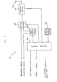
board repeater 16 is shown. Therepeater 16 is generally constituted by acontrol section 24, asignal generating section 26, aswitching section 28, a transmittingsection 30, anantenna 32, and a portableunit detecting section 34. The portableunit detecting section 34 delivers to the control section 24 a signal which is representative of the presence/absence of theportable unit 18 on therepeater 16. For example, as shown in Fig. 4A, the detectingsection 34 produces an output which is logical ONE when theportable unit 18 is present on therepeater 16 and logical ZERO when it is absent. - In detail, in response to a call receive signal from the on-
board unit 14, thecontrol section 24 of the repeater checks the output level of the portableunit detecting section 34 and, if it is ONE, does not perform any operation as in a conventional vehicle telephone for business use. On the other hand, when a call receive signal, Fig. 4B, is applied from the on-board unit 14 to therepeater 16 while the output level of thedetecting section 34 is ZERO, thecontrol section 24 energizes thesignal generating section 26 causing it to generate anabsence answer signal 36, arepeat start signal 38, and acall signal 42. Simultaneously, thecontrol section 24 turns ON a press signal Fig. 4D, and generates a microphone signal, Fig. 4C, the press signal and microphone signal being fed to the on-board unit 14. - The microphone signal consists of the previously stated absence answer signal and repeat start signal. As shown in Fig. 4C, the
absence answer signal 36 is sent first and, then, therepeat start signal 38, At the same time, thecontrol section 24 connects theswitching section 28 to thesignal generating section 26 while controlling the transmittingsection 30. As a result, thecall signal 42 outputted by thesignal generating section 26 is transmitted through theantenna 32 to theportable unit 18 over thechannel 22. Subsequently, thecontrol section 24 actuates theswitching section 28 into connection with the on-board unit 14 while controlling the transmittingsection 30. This causes the receiver signal, i.e.,voice message 40 applied from theunit 14 to be transmitted, as avoice message 44, to theportable unit 18 over the channel 22 (see Fig. 4E). Hence, the signal received by theportable unit 18 consists of thecall signal 42 and thevoice message 44, as shown in Fig. 4F. - The on-
board repeater 16 is disenabled when the call signal from the on-board unit 14 becomes OFF, when a timer built in thecontrol section 24 is counts up a predetermined period of time, or the like. - As shown in Fig. 5, the
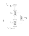
portable unit 18 includes anantenna 46, a receivingsection 48, aswitch section 50, aspeaker 52, and a control section 54. The call signal 56 andvoice message 58 which constitute a received signal, Fig. 6A, and come in through theantenna 46 are demodulated by the receivingsection 48, the call signal 56 being fed to the control section 54 first. The call signal 56 and thevoice message 58 correspond to thecall signal 42 and thevoice message 44, respectively. In response, the control section 54 decodes the call signal 56 and, if it is meant for the own unit, controls theswitch section 50 to connect the receivingsection 48 to thespeaker 52. Consequently, thevoice message 58 which follows the call signal 56 is applied from the receivingsection 48 to thespeaker 52 resulting that the voice message is produced through the speaker 52 (see Fig. 6B). - With the above construction, the paging system in accordance with the present invention allows a voice message to be promptly transferred to a salesman or the like who is away from the vehicle with the
portable unit 18. A timer is installed in the control section 54 so that theportable unit 18 may be disenabled upon the lapse of a predetermined period of time. - In summary, it will be seen that the present invention provides a paging system which is capable of transferring a desired voice message to a person, who is expected to use a vehicle telephone for business purpose, promptly or immediately without resorting to the conventional troublesome procedure even if he or she is away from a vehicle on which the telephone is mounted. This unprecedented advantage is derived from a unique arrangement wherein an on-board radio unit and an on-board repeater are mounted on the same vehicle with a portable unit removably mounted on the repeater, the on-board unit serving as a repeater when the portable unit is removed from the on-board repeater. Another advantage attainable with the present invention is that a desired paging system can be constructed simply by mounting the on-board repeater with the portable unit in the same vehicle as the on-board radio unit.
- Various modifications will become possible for those skilled in the art after receiving the teachings of the present disclosure without departing from the scope thereof.
Claims (3)
a central radio station for collectively controlling said system;
an on-board radio unit connected to said central radio station by a first channel to receive a first call signal and a voice message from said central radio station while transmitting to said central radio station an absence answer signal and a repeat start signal which are generated at said on-board radio unit;
an on-board repeater electrically connected to said on-board radio unit and mounted on the same vehicle as said on-board radio unit; and
a portable unit removably mounted on said on-board repeater and, when removed from said repeater to be carried, connected to said repeater by a second channel which is different from said first channel.
detector means for detecting whether or not said portable unit is mounted on said on-board repeater;
signal generating means for generating said absence answer signal, said repeat start signal and a second call signal which is meant for said portable unit; and
control means for, when said portable unit is not mounted on said on-board repeater, responding to a call receive signal, which said on-board radio unit produces in response to said first call signal, by controlling said signal generating means to send said absence answer signal and said repeat start signal to said on-board radio unit while, at the same time, sending said second call signal to said portable unit, said control means sending said voice message to said portable unit.
Applications Claiming Priority (2)
| Application Number | Priority Date | Filing Date | Title |
|---|---|---|---|
| JP44639/87 | 1987-02-27 | ||
| JP62044639A JPH0650840B2 (en) | 1987-02-27 | 1987-02-27 | Wireless selective calling system |
Publications (3)
| Publication Number | Publication Date |
|---|---|
| EP0280543A2 true EP0280543A2 (en) | 1988-08-31 |
| EP0280543A3 EP0280543A3 (en) | 1989-11-23 |
| EP0280543B1 EP0280543B1 (en) | 1993-12-29 |
Family
ID=12697000
Family Applications (1)
| Application Number | Title | Priority Date | Filing Date |
|---|---|---|---|
| EP88301604A Expired - Lifetime EP0280543B1 (en) | 1987-02-27 | 1988-02-25 | Paging system |
Country Status (5)
| Country | Link |
|---|---|
| US (1) | US4906989A (en) |
| EP (1) | EP0280543B1 (en) |
| JP (1) | JPH0650840B2 (en) |
| AU (1) | AU599458B2 (en) |
| CA (1) | CA1281776C (en) |
Cited By (19)
| Publication number | Priority date | Publication date | Assignee | Title |
|---|---|---|---|---|
| GB2241850A (en) * | 1990-03-08 | 1991-09-11 | Marconi Co Ltd | Signal transmission system |
| DE4022959A1 (en) * | 1990-07-19 | 1992-01-23 | Telefonbau & Normalzeit Gmbh | ANRUFORGAN FOR TELECOMMUNICATION TERMINALS |
| WO1992002084A1 (en) * | 1990-07-25 | 1992-02-06 | Norand Corporation | Multi-level radio-frequency communication system |
| US5404391A (en) * | 1991-10-03 | 1995-04-04 | Developpement Des Technologies M.W.M. Inc. | Incoming call alert system for cellular telephones without wired connection thereto |
| DE4334631A1 (en) * | 1993-10-06 | 1995-04-13 | Koepenick Funkwerk Gmbh | Mobile, linear radio network |
| US5551056A (en) * | 1993-08-17 | 1996-08-27 | Nokia Telecommunications Oy | Method for securing the operation of a telecommunications network in a cellular radio system and a base station arrangement |
| DE19527792A1 (en) * | 1995-07-19 | 1997-01-23 | Deutsche Telephonwerk Kabel | Call-relaying system esp. for secondary receivers of mobile radio device |
| DE19539507A1 (en) * | 1995-10-24 | 1997-05-15 | Siemens Ag | Digital mobile telephone with digital radio interfaces |
| DE19614925A1 (en) * | 1996-04-16 | 1997-10-23 | Konrad Reuther | Mobile telephone for signal transmission to relay station |
| WO1998057444A1 (en) * | 1997-06-13 | 1998-12-17 | Ericsson Inc. | Dual-mode satellite/cellular phone architecture with physically separable modes |
| US6006100A (en) * | 1990-05-25 | 1999-12-21 | Norand Corporation | Multi-level, hierarchical radio-frequency communication system |
| EP1052863A2 (en) * | 1999-05-11 | 2000-11-15 | Kyocera Corporation | Multimode mobile telephone apparatus |
| DE10007806A1 (en) * | 2000-02-21 | 2001-09-20 | Becker Gmbh | Method for operating a radio installed in a vehicle and a portable radio telephone |
| US6614768B1 (en) | 1989-04-28 | 2003-09-02 | Broadcom Corporation | Enhanced mobility and address resolution in a wireless premises based network |
| US6647244B1 (en) * | 1999-11-16 | 2003-11-11 | The Whitaker Corporation | Wireless vehicular repeater system |
| US6654378B1 (en) | 1992-03-18 | 2003-11-25 | Broadcom Corp. | Transaction control system including portable data terminal and mobile customer service station |
| US7080788B2 (en) | 1989-04-14 | 2006-07-25 | Broadcom Corporation | Modular, portable data processing terminal for use in a radio frequency communication network |
| US7853254B2 (en) | 1993-08-31 | 2010-12-14 | Broadcom Corp. | Modular, portable data processing terminal for use in a radio frequency communication network |
| US7885242B2 (en) | 1993-12-23 | 2011-02-08 | Broadcom Corp. | Enhanced mobility and address resolution in a wireless premises based network |
Families Citing this family (31)
| Publication number | Priority date | Publication date | Assignee | Title |
|---|---|---|---|---|
| JP2718089B2 (en) * | 1988-09-21 | 1998-02-25 | 松下電器産業株式会社 | Radio selective calling device |
| US5163158A (en) * | 1989-01-12 | 1992-11-10 | Tendler Robert K | Modular communications system including a portable unit range extender and selective-call system |
| US4952929A (en) * | 1989-04-17 | 1990-08-28 | Motorola, Inc. | Selective call receiving system |
| JPH033433A (en) * | 1989-05-31 | 1991-01-09 | Nec Corp | Radio communication system |
| US5117449A (en) * | 1989-11-03 | 1992-05-26 | Motorola, Inc. | Dual receiver apparatus for integrated paging and radiotelephone functions |
| US6749122B1 (en) * | 1990-05-25 | 2004-06-15 | Broadcom Corporation | Multi-level hierarchial radio-frequency system communication system |
| US6359872B1 (en) * | 1997-10-28 | 2002-03-19 | Intermec Ip Corp. | Wireless personal local area network |
| JP2887815B2 (en) * | 1990-08-08 | 1999-05-10 | アイシン精機株式会社 | Mobile station position monitoring system |
| US5239666A (en) * | 1991-03-11 | 1993-08-24 | Motorola, Inc. | Mobile detector using RSSI for vehicular repeater prioritization |
| DE69225925T2 (en) * | 1991-04-17 | 1998-10-22 | Ericsson Telefon Ab L M | Cellular communication system with integrated paging system |
| US5311570A (en) * | 1991-05-10 | 1994-05-10 | At&T Bell Laboratories | Integration of wireless paging in a communication system |
| EP0522782B1 (en) * | 1991-07-09 | 1997-01-08 | Mitsubishi Denki Kabushiki Kaisha | Cordless telephone system for moving conveyances |
| US5533097A (en) * | 1992-02-26 | 1996-07-02 | Motorola, Inc. | Portable communication system comprising a local and wide area communication units which can store a communication when the wide area communication system is not available |
| US5432839A (en) * | 1992-08-31 | 1995-07-11 | Motorola, Inc. | Method and apparatus for forwarding selective call messages received in a first selective call service to a second selective call service |
| JP2546501B2 (en) * | 1993-07-12 | 1996-10-23 | 日本電気株式会社 | Radiotelephone device, radiotelephone system including the same, and radiotelephone response method |
| US5495519A (en) * | 1993-10-04 | 1996-02-27 | E Lead Electronic Co., Ltd. | Control circuit for control of peripheral equipment of wireless communication appliance |
| US5481590A (en) * | 1994-10-26 | 1996-01-02 | At&T Corp. | Selection of a communication terminal for receiving an incoming call |
| US5867796A (en) * | 1995-04-28 | 1999-02-02 | Nec Corporation | Portable telephone set capable of being put in a holding mode by operation of a vibration unit which is for announcing reception of an incoming call to a user |
| AU5235596A (en) * | 1995-05-19 | 1996-11-28 | Nec Corporation | Radio paging system using radio selective paging receiver |
| US5598459A (en) * | 1995-06-29 | 1997-01-28 | Ericsson Inc. | Authentication and handover methods and systems for radio personal communications |
| US5722071A (en) * | 1996-03-27 | 1998-02-24 | Sony Corporation | Portable receiver including transducer for notifying user of messages received in a remote mobile communications device |
| GB2317288B (en) * | 1996-09-13 | 2001-03-28 | Motorola Gmbh | Mobile radio and method of operation |
| US6002937A (en) * | 1996-10-31 | 1999-12-14 | Motorola, Inc. | Method of and apparatus for communicating information signals |
| JP3276572B2 (en) * | 1996-12-20 | 2002-04-22 | 富士通株式会社 | Digital multiplex radio equipment |
| US5995804A (en) * | 1997-01-16 | 1999-11-30 | Flash Comm. Inc. | Repeater station for augmenting the coverage area of a paging system |
| US6140937A (en) * | 1997-03-17 | 2000-10-31 | Sony Corporation | Modular pager unit removably incorporated with a personal electronic device |
| US6119022A (en) * | 1997-03-18 | 2000-09-12 | Ericsson Inc. | System for alerting portable communication device user of incoming call |
| US6154148A (en) * | 1997-12-22 | 2000-11-28 | Prince Corporation | Vehicle-to-individual paging system |
| US6223062B1 (en) * | 1998-05-15 | 2001-04-24 | Northrop Grumann Corporation | Communications interface adapter |
| US6104712A (en) * | 1999-02-22 | 2000-08-15 | Robert; Bruno G. | Wireless communication network including plural migratory access nodes |
| CN114389669B (en) * | 2020-10-20 | 2023-04-07 | 上海华为技术有限公司 | Communication equipment, communication enhancement device and antenna integrated component |
Citations (5)
| Publication number | Priority date | Publication date | Assignee | Title |
|---|---|---|---|---|
| US3745462A (en) * | 1972-01-20 | 1973-07-10 | Public Syst Inc | Mobile radio extension interface for converting conventional transmit/receive to a repeater |
| JPS5599853A (en) * | 1979-01-23 | 1980-07-30 | Fujitsu Ltd | Absence transfer and processing system for mobile subscriber |
| EP0035590A1 (en) * | 1980-03-03 | 1981-09-16 | Robert Bosch Gmbh | Radio apparatus for a vehicle |
| US4539706A (en) * | 1983-02-03 | 1985-09-03 | General Electric Company | Mobile vehicular repeater system which provides up-link acknowledgement signal to portable transceiver at end of transceiver transmission |
| DE3528886A1 (en) * | 1985-08-12 | 1987-02-19 | Siemens Ag | Radiotelephony system |
Family Cites Families (13)
| Publication number | Priority date | Publication date | Assignee | Title |
|---|---|---|---|---|
| US3736591A (en) * | 1970-10-30 | 1973-05-29 | Motorola Inc | Receiving antenna for miniature radio receiver |
| US4056779A (en) * | 1976-04-05 | 1977-11-01 | Motorola, Inc. | Vehicular repeater |
| DE2805420A1 (en) * | 1978-02-09 | 1979-08-16 | Bosch Gmbh Robert | RADIO SYSTEM FOR TRANSMISSION OF MESSAGES |
| JPS591016B2 (en) * | 1980-03-26 | 1984-01-10 | 日本電気株式会社 | Mobile phone relay method |
| GB8317995D0 (en) * | 1983-07-01 | 1983-08-03 | Sommerhoff G W C | Scriptwriter for blind |
| US4661972A (en) * | 1985-02-18 | 1987-04-28 | Nec Corporation | Mobile telephone system for automatically paging absent mobile subscriber |
| GB2177244B (en) * | 1985-06-26 | 1988-08-17 | Multitone Electronics Plc | Paging system |
| JPH06105884B2 (en) * | 1986-05-06 | 1994-12-21 | 日本電気株式会社 | Wireless telephone system |
| KR880702023A (en) * | 1986-08-05 | 1988-11-07 | 세이죠 이와이 | Transceiver for telephone with wired / wireless handset |
| US4700375A (en) * | 1986-10-10 | 1987-10-13 | Motorola, Inc. | Battery charging, reset, and data transfer system |
| US4803487A (en) * | 1987-04-30 | 1989-02-07 | Motorola, Inc. | Portable communications receiver with separate information presentation means |
| IL85558A (en) * | 1987-04-30 | 1992-01-15 | Motorola Inc | Personal message receiving device with separate information presentation means |
| AU2628988A (en) * | 1987-11-13 | 1989-06-01 | Superior Electronic Developments Pty. Ltd. | Communications apparatus |
-
1987
- 1987-02-27 JP JP62044639A patent/JPH0650840B2/en not_active Expired - Fee Related
-
1988
- 1988-02-25 EP EP88301604A patent/EP0280543B1/en not_active Expired - Lifetime
- 1988-02-25 AU AU12183/88A patent/AU599458B2/en not_active Ceased
- 1988-02-26 CA CA000559925A patent/CA1281776C/en not_active Expired
-
1989
- 1989-07-28 US US07/385,958 patent/US4906989A/en not_active Expired - Lifetime
Patent Citations (5)
| Publication number | Priority date | Publication date | Assignee | Title |
|---|---|---|---|---|
| US3745462A (en) * | 1972-01-20 | 1973-07-10 | Public Syst Inc | Mobile radio extension interface for converting conventional transmit/receive to a repeater |
| JPS5599853A (en) * | 1979-01-23 | 1980-07-30 | Fujitsu Ltd | Absence transfer and processing system for mobile subscriber |
| EP0035590A1 (en) * | 1980-03-03 | 1981-09-16 | Robert Bosch Gmbh | Radio apparatus for a vehicle |
| US4539706A (en) * | 1983-02-03 | 1985-09-03 | General Electric Company | Mobile vehicular repeater system which provides up-link acknowledgement signal to portable transceiver at end of transceiver transmission |
| DE3528886A1 (en) * | 1985-08-12 | 1987-02-19 | Siemens Ag | Radiotelephony system |
Non-Patent Citations (1)
| Title |
|---|
| PATENT ABSTRACTS OF JAPAN, vol. 4, no. 148 (E-30)[630], 18th October 1980, page 91 E 30; & JP-A-55 099 853 (FUJITSU K.K.) 30-07-1980 * |
Cited By (32)
| Publication number | Priority date | Publication date | Assignee | Title |
|---|---|---|---|---|
| US7080788B2 (en) | 1989-04-14 | 2006-07-25 | Broadcom Corporation | Modular, portable data processing terminal for use in a radio frequency communication network |
| US6614768B1 (en) | 1989-04-28 | 2003-09-02 | Broadcom Corporation | Enhanced mobility and address resolution in a wireless premises based network |
| US7757956B2 (en) | 1990-01-18 | 2010-07-20 | Broadcom Corporation | Modular, portable data processing terminal for use in a radio frequency communication network |
| GB2241850B (en) * | 1990-03-08 | 1994-05-25 | Marconi Co Ltd | Signal transmission system |
| GB2241850A (en) * | 1990-03-08 | 1991-09-11 | Marconi Co Ltd | Signal transmission system |
| US6006100A (en) * | 1990-05-25 | 1999-12-21 | Norand Corporation | Multi-level, hierarchical radio-frequency communication system |
| DE4022959A1 (en) * | 1990-07-19 | 1992-01-23 | Telefonbau & Normalzeit Gmbh | ANRUFORGAN FOR TELECOMMUNICATION TERMINALS |
| WO1992002084A1 (en) * | 1990-07-25 | 1992-02-06 | Norand Corporation | Multi-level radio-frequency communication system |
| EP1378815A2 (en) * | 1990-07-25 | 2004-01-07 | Broadcom Corporation | Multi-level radio-frequency communication system |
| EP0752763A2 (en) * | 1990-07-25 | 1997-01-08 | Norand Corporation | Multi-level radio-frequency communication system |
| EP0752763A3 (en) * | 1990-07-25 | 1997-02-26 | Norand Corp | Multi-level radio-frequency communication system |
| EP1378815A3 (en) * | 1990-07-25 | 2007-10-31 | Broadcom Corporation | Multi-level radio-frequency communication system |
| US5404391A (en) * | 1991-10-03 | 1995-04-04 | Developpement Des Technologies M.W.M. Inc. | Incoming call alert system for cellular telephones without wired connection thereto |
| US6654378B1 (en) | 1992-03-18 | 2003-11-25 | Broadcom Corp. | Transaction control system including portable data terminal and mobile customer service station |
| US5551056A (en) * | 1993-08-17 | 1996-08-27 | Nokia Telecommunications Oy | Method for securing the operation of a telecommunications network in a cellular radio system and a base station arrangement |
| US7853254B2 (en) | 1993-08-31 | 2010-12-14 | Broadcom Corp. | Modular, portable data processing terminal for use in a radio frequency communication network |
| US7992788B2 (en) | 1993-08-31 | 2011-08-09 | Broadcom Corporation | Method used by a communication device for use in a communication channel |
| DE4334631A1 (en) * | 1993-10-06 | 1995-04-13 | Koepenick Funkwerk Gmbh | Mobile, linear radio network |
| US7885242B2 (en) | 1993-12-23 | 2011-02-08 | Broadcom Corp. | Enhanced mobility and address resolution in a wireless premises based network |
| DE19527792A1 (en) * | 1995-07-19 | 1997-01-23 | Deutsche Telephonwerk Kabel | Call-relaying system esp. for secondary receivers of mobile radio device |
| DE19527792B4 (en) * | 1995-07-19 | 2006-05-04 | Funkwerk Köpenick GmbH | Call forwarding to secondary call receiver |
| DE19539507A1 (en) * | 1995-10-24 | 1997-05-15 | Siemens Ag | Digital mobile telephone with digital radio interfaces |
| DE19614925C2 (en) * | 1996-04-16 | 2001-10-25 | Konrad Reuther | Mobile telephone and method for transmitting electrical signals |
| DE19614925A1 (en) * | 1996-04-16 | 1997-10-23 | Konrad Reuther | Mobile telephone for signal transmission to relay station |
| US6134437A (en) * | 1997-06-13 | 2000-10-17 | Ericsson Inc. | Dual-mode satellite/cellular phone architecture with physically separable mode |
| WO1998057444A1 (en) * | 1997-06-13 | 1998-12-17 | Ericsson Inc. | Dual-mode satellite/cellular phone architecture with physically separable modes |
| US6317582B1 (en) | 1999-05-11 | 2001-11-13 | Kyocera Corporation | Multimode mobile telephone apparatus |
| EP1052863A3 (en) * | 1999-05-11 | 2000-12-20 | Kyocera Corporation | Multimode mobile telephone apparatus |
| EP1052863A2 (en) * | 1999-05-11 | 2000-11-15 | Kyocera Corporation | Multimode mobile telephone apparatus |
| US6647244B1 (en) * | 1999-11-16 | 2003-11-11 | The Whitaker Corporation | Wireless vehicular repeater system |
| DE10007806C2 (en) * | 2000-02-21 | 2002-05-29 | Harman Becker Automotive Sys | Method for operating a radio installed in a vehicle and a portable radio telephone |
| DE10007806A1 (en) * | 2000-02-21 | 2001-09-20 | Becker Gmbh | Method for operating a radio installed in a vehicle and a portable radio telephone |
Also Published As
| Publication number | Publication date |
|---|---|
| CA1281776C (en) | 1991-03-19 |
| JPS63211929A (en) | 1988-09-05 |
| AU599458B2 (en) | 1990-07-19 |
| EP0280543A3 (en) | 1989-11-23 |
| EP0280543B1 (en) | 1993-12-29 |
| JPH0650840B2 (en) | 1994-06-29 |
| US4906989A (en) | 1990-03-06 |
| AU1218388A (en) | 1988-09-01 |
Similar Documents
| Publication | Publication Date | Title |
|---|---|---|
| US4906989A (en) | Paging system having a vehicle mounted repeater with a portable paging receiver detachably mounted thereon | |
| EP0462982B1 (en) | Paging system with improved acknowledge-back capabilities | |
| EP2114059B1 (en) | Cellular mobile telephone apparatus and method for transmitting a response message to an incoming call | |
| KR100274274B1 (en) | A cellular mobile telephone apparatus and an alarm device therefor | |
| EP0489838B1 (en) | Battery saver for a tdm system | |
| ES2156438T3 (en) | SYSTEM TO ALERT A USER OF A PORTABLE COMMUNICATIONS DEVICE OF AN INPUT CALL. | |
| EP0218450B2 (en) | Control system of a radio telephone apparatus | |
| JPH10243086A (en) | Telephone system | |
| US5790593A (en) | System for setting up a wireless connection for exchanging information with another system, which system is provided with a transceiver device for transmitting and receiving information in a wireless manner, and also modulator/demodulator device | |
| KR100313853B1 (en) | Method for receiving short message at power-on state of mobile terminal and receipt controlling device according to the method | |
| JPS6281821A (en) | Radio communication system | |
| KR100239176B1 (en) | Apparatus and method for automatically retrying call connection in a radio communication terminal | |
| JP4207057B2 (en) | Telephone equipment | |
| JP2586440B2 (en) | Mobile communication system | |
| EP0746132A2 (en) | Paging system for a cordless telephone | |
| JPH1013507A (en) | Portable telephone set and method for confirming key operation | |
| JP2539255B2 (en) | Loudspeaker calling method and radio device therefor | |
| GB2300954A (en) | Radio paging system | |
| JPH06164701A (en) | Cordless automatic answering telephone set | |
| JPH09252270A (en) | Call reply device | |
| JP2001036634A (en) | Facsimile machine with automatic answering operation function | |
| JPH08149182A (en) | Calling device | |
| JPH0295035A (en) | Additional calling system for automobile telephone | |
| JPH06164448A (en) | Radio transceiver device | |
| JPH0946748A (en) | Radio calling system using selective radio call receiver |
Legal Events
| Date | Code | Title | Description |
|---|---|---|---|
| PUAI | Public reference made under article 153(3) epc to a published international application that has entered the european phase |
Free format text: ORIGINAL CODE: 0009012 |
|
| 17P | Request for examination filed |
Effective date: 19880317 |
|
| AK | Designated contracting states |
Kind code of ref document: A2 Designated state(s): GB NL SE |
|
| PUAL | Search report despatched |
Free format text: ORIGINAL CODE: 0009013 |
|
| AK | Designated contracting states |
Kind code of ref document: A3 Designated state(s): GB NL SE |
|
| 17Q | First examination report despatched |
Effective date: 19920427 |
|
| GRAA | (expected) grant |
Free format text: ORIGINAL CODE: 0009210 |
|
| AK | Designated contracting states |
Kind code of ref document: B1 Designated state(s): GB NL SE |
|
| PG25 | Lapsed in a contracting state [announced via postgrant information from national office to epo] |
Ref country code: SE Effective date: 19931229 Ref country code: NL Effective date: 19931229 |
|
| NLV1 | Nl: lapsed or annulled due to failure to fulfill the requirements of art. 29p and 29m of the patents act | ||
| PLBE | No opposition filed within time limit |
Free format text: ORIGINAL CODE: 0009261 |
|
| STAA | Information on the status of an ep patent application or granted ep patent |
Free format text: STATUS: NO OPPOSITION FILED WITHIN TIME LIMIT |
|
| 26N | No opposition filed | ||
| REG | Reference to a national code |
Ref country code: GB Ref legal event code: IF02 |
|
| PGFP | Annual fee paid to national office [announced via postgrant information from national office to epo] |
Ref country code: GB Payment date: 20020227 Year of fee payment: 15 |
|
| PG25 | Lapsed in a contracting state [announced via postgrant information from national office to epo] |
Ref country code: GB Free format text: LAPSE BECAUSE OF NON-PAYMENT OF DUE FEES Effective date: 20030225 |
|
| GBPC | Gb: european patent ceased through non-payment of renewal fee |