EP0282210A1 - Apparatus for monitoring a bloodstream - Google Patents
Apparatus for monitoring a bloodstream Download PDFInfo
- Publication number
- EP0282210A1 EP0282210A1 EP88301716A EP88301716A EP0282210A1 EP 0282210 A1 EP0282210 A1 EP 0282210A1 EP 88301716 A EP88301716 A EP 88301716A EP 88301716 A EP88301716 A EP 88301716A EP 0282210 A1 EP0282210 A1 EP 0282210A1
- Authority
- EP
- European Patent Office
- Prior art keywords
- bloodstream
- light receiving
- laser
- laser light
- laser beam
- Prior art date
- Legal status (The legal status is an assumption and is not a legal conclusion. Google has not performed a legal analysis and makes no representation as to the accuracy of the status listed.)
- Granted
Links
- 238000012544 monitoring process Methods 0.000 title claims abstract description 13
- 238000005070 sampling Methods 0.000 claims description 5
- 239000003086 colorant Substances 0.000 claims description 2
- 230000003287 optical effect Effects 0.000 claims 3
- 210000000601 blood cell Anatomy 0.000 abstract description 3
- 239000013307 optical fiber Substances 0.000 description 5
- 210000004204 blood vessel Anatomy 0.000 description 4
- 238000003745 diagnosis Methods 0.000 description 3
- 230000035945 sensitivity Effects 0.000 description 3
- 210000004369 blood Anatomy 0.000 description 2
- 239000008280 blood Substances 0.000 description 2
- 238000001514 detection method Methods 0.000 description 2
- 238000010586 diagram Methods 0.000 description 2
- 230000004044 response Effects 0.000 description 2
- 239000000523 sample Substances 0.000 description 2
- 230000002159 abnormal effect Effects 0.000 description 1
- 238000009825 accumulation Methods 0.000 description 1
- 238000010276 construction Methods 0.000 description 1
- 230000003247 decreasing effect Effects 0.000 description 1
- 230000000694 effects Effects 0.000 description 1
- 238000009499 grossing Methods 0.000 description 1
- 238000000034 method Methods 0.000 description 1
- 239000002245 particle Substances 0.000 description 1
- 238000001931 thermography Methods 0.000 description 1
Images


Classifications
-
- A—HUMAN NECESSITIES
- A61—MEDICAL OR VETERINARY SCIENCE; HYGIENE
- A61B—DIAGNOSIS; SURGERY; IDENTIFICATION
- A61B5/00—Measuring for diagnostic purposes; Identification of persons
- A61B5/44—Detecting, measuring or recording for evaluating the integumentary system, e.g. skin, hair or nails
- A61B5/441—Skin evaluation, e.g. for skin disorder diagnosis
-
- A—HUMAN NECESSITIES
- A61—MEDICAL OR VETERINARY SCIENCE; HYGIENE
- A61B—DIAGNOSIS; SURGERY; IDENTIFICATION
- A61B5/00—Measuring for diagnostic purposes; Identification of persons
- A61B5/0059—Measuring for diagnostic purposes; Identification of persons using light, e.g. diagnosis by transillumination, diascopy, fluorescence
- A61B5/0062—Arrangements for scanning
- A61B5/0064—Body surface scanning
-
- A—HUMAN NECESSITIES
- A61—MEDICAL OR VETERINARY SCIENCE; HYGIENE
- A61B—DIAGNOSIS; SURGERY; IDENTIFICATION
- A61B5/00—Measuring for diagnostic purposes; Identification of persons
- A61B5/02—Detecting, measuring or recording pulse, heart rate, blood pressure or blood flow; Combined pulse/heart-rate/blood pressure determination; Evaluating a cardiovascular condition not otherwise provided for, e.g. using combinations of techniques provided for in this group with electrocardiography or electroauscultation; Heart catheters for measuring blood pressure
- A61B5/026—Measuring blood flow
- A61B5/0261—Measuring blood flow using optical means, e.g. infrared light
Definitions
- the present invention relates to an apparatus for monitoring a bloodstream flowing through a blood vessel, and more particularly to an apparatus for measuring a distribution and a variation in time of an average velocity of a bloodstream in a skin surface of a patient by means of the laser speckle method.
- the variation in time of the bloodstream at a point is detected with the aid of an optical fibre scope, or any abnormal condition is detected by comparing the measured data with data from a standard reference point.
- the existing apparatus is not suitable to estimate the bloodstream in a rather large area.
- the signal obtained via the optical fiber scope is inherently noisy, there must be provided an integrating circuit or low pass filter for smoothing the noisy signal. When the time constant of these circuits is made large, the variation of the bloodstream can be displayed slowly, but the sensitivity to any rapid change in the bloodstream is decreased.
- the present invention provides an apparatus for monitoring a bloodstream comprising light projecting means for projecting a laser light upon an object; and light receiving means for receiving laser light reflected from the object; characterised in that the light receiving means comprises a plurality of light receiving elements, and in that the apparatus further comprises memory means for storing output signals read out of the light receiving elements; calculating means for processing the output signals stored in said memory means to derive information about a bloodstream of the object; and display means for displaying the information about the bloodstream.
- the apparatus of the present invention is advantageous relative to the existing laser Doppler bloodstream meter using an optical fibre probe because it can respond more quickly to changes in the bloodstream velocity.
- a further advantage is that the variation of the bloodstream over a larger skin surface can be measured. In this way the information obtained is more useful for diagnosis.
- FIG. 1 is a perspective view showing schematically an embodiment of the bloodstream monitoring apparatus according to the invention.
- the apparatus comprises a laser light source L for projecting a laser light beam B upon a skin surface S.
- the laser light source L comprises a laser for emitting a laser beam and a cylindrical lens for converting the laser beam emitted from the laser into a rectilinear beam having a width of several centimeters.
- the laser light reflected by the skin surface S is incident upon a linear line sensor 2 via an objective lens 1.
- the linear line sensor 2 comprises a number of light receiving elements arranged in one direction. On the light receiving surface of the line sensor 2 there is formed the speckle pattern which varies in time in accordance with the movement of blood cells in blood vessels within the skin surface S. Therefore, by scanning the line sensor 2, there may be obtained photoelectric signals representing the variation in time of the speckle pattern.
- Figures 2(a) and 2(b) are graphs showing the variation in time of the output signal from the line sensor 2, while the laser light is incident upon the skin surface S at the same point. Solid line and broken curves represent the output signals at different timings.
- Figure 2(a) shows the output signals when the bloodstream velocity is high, and the curve shown in Figure 2(b) denotes the output signals when the velocity of the bloodstream is low.
- the output signal at the second timing is greatly different from that at the first timing due to the large variation of the speckle pattern.
- the output signals at the first and second timings shown in Figure 2(b) are substantially the same as each other, because the variation of the speckle pattern is small.
- Figure 3 is a block diagram showing a signal processing unit. An output signal from the line sensor 2 is successively supplied to video amplifier 3, A/D converter 4, memory 5 and display 6. These circuits are connected to a microcomputer 7 and are controlled by the microcomputer and signals are transmitted between the circuits and the microcomputer.
- the line sensor 2 comprises 256 light receiving elements and output signals successively read out of the elements are amplified by the video amplifier 3 and are converted into digital signals by the high speed A/D converter 4. These digital signals are then stored in the memory 5. Under the control of the program stored in the microcomputer 7, differences between output signals at successive samplings from each of the light receiving elements are calculated and then these differences thus calculated are accumulated. The calculation is carried out in the following manner.
- the accumulation value V(t) can be calculated as follows.
- the accumulated value V(t) is proportional to the average velocity of the bloodstream at the timing t.
- the above calculation is performed at a high speed, and the calculated value is displayed on the display 6 as a series of waveforms or is supplied to a recorder. In this manner, the variation in time of the bloodstream can be measured.
- the variation of the bloodstream velocity in time is measured.
- Figure 4(a) shows output signals read out of the line sensor 2 at two successive timings, while the laser beam is incident upon a position of the skin surface.
- the blood stream velicity is high, while in the left hand half, the bloodstream velocity is low.
- the pattern shows the large variation, values of the output signals at respective light receiving elements differ largely from each other, but in the left hand half, the differences are small. Therefore, when these differences are accumulated for respective light receiving elements for a predetermined period, it is possible to obtain the distribution of the bloodstream velocity in the scanning line as shown in Figure 4(b).
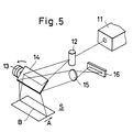
- FIG. 5 is a perspective view illustrating another embodiment of the bloodstream monitoring apparatus according to the invention.
- the two dimensional distribution of the bloodstream is measured with the aid of the linear line sensor.
- a laser light beam emitted from a He-Ne laser light source 11 is expanded in one direction by means of a cylindrical lens 12 and is made incident upon the skin surface S via a reflection mirror 14 which is swung by an electric motor 13 at a constant speed. Therefore, the skin surface S is scanned with the laser beam in a direction A shown in Figure 5.
- the laser beam reflected by the skin surface S is reflected again by the swinging mirror 14 and is then made incident upon a line sensor 16 via an objective lens 15.
- the skin surface S is scanned two-dimensionally and a two-dimensional map of the bloodstream can be formed.
- a map is quite useful for diagnosis.
- the map may be displayed on a color monitor in such a manner that different velocities of the bloodstream velocity are displayed with different colors. With the aid of such a colored map, it is possible to grasp the condition of the bloodstream in fine blood vessels at a glance.
- Such a colored map may be effectively used together with a thermography image of the area.
- the scattered light is detected by the linear line sensor, but it is also possible to detect the scattered light by means of a two-dimensional image sensor.
- the variation in time of the bloodstream velocity and the bloodstream distribution may be detected two-dimensionally. In this case, a laser beam expanded in two orthogonal directions has to be made incident upon the object.
- the useful data may be obtained without moving the object and measuring system relative to each other by expanding the laser light two-dimensionally.
- the bloodstream monitoring apparatus it is possible to display the variation of the bloodstream and the distribution of the bloodstream which are very useful for diagnosis.
- the response for the bloodstream change is very high and the field of detection can be made wider.
Abstract
Description
- The present invention relates to an apparatus for monitoring a bloodstream flowing through a blood vessel, and more particularly to an apparatus for measuring a distribution and a variation in time of an average velocity of a bloodstream in a skin surface of a patient by means of the laser speckle method.
- When laser light is incident upon a living tissue such as skin, the laser light is scattered by particles constituting the blood, and scattered light rays interfere with each other to form a random pattern, i.e. a speckle pattern. This speckle pattern changes in time due to the movement of the blood cells in the blood vessel. Therefore there can be derived a noise-like signal representing the velocity of the bloodstream by measuring the variation in time of the intensity of light scattered from a certain point on the skin. This phenomenon was found by Dr. M.D. Stern et al around the year 1975. By utilizing this phenomenon, the bloodstream can be measured with the aid of frequency analysis of the speckle signal without damaging the skin. The study of this phenomenon has been rapidly developed and the apparatus for monitoring the bloodstream has been commercially available as the laser Doppler bloodstream meter.
- In the known apparatus, the variation in time of the bloodstream at a point is detected with the aid of an optical fibre scope, or any abnormal condition is detected by comparing the measured data with data from a standard reference point. However, in the known laser Doppler bloodstream meter using the optical fibre, since an area of the detection point has a very small diameter such as several millimeters, the measured data fluctuates for respective measuring points. Therefore, the existing apparatus is not suitable to estimate the bloodstream in a rather large area. Further, since the signal obtained via the optical fiber scope is inherently noisy, there must be provided an integrating circuit or low pass filter for smoothing the noisy signal. When the time constant of these circuits is made large, the variation of the bloodstream can be displayed slowly, but the sensitivity to any rapid change in the bloodstream is decreased.
- This inability to display the variation in time of the bloodsteam with a high response sensitivity, or to indicate the distribution of the bloodstream activity represents a technical problem.
- The present invention provides an apparatus for monitoring a bloodstream comprising light projecting means for projecting a laser light upon an object; and light receiving means for receiving laser light reflected from the object; characterised in that the light receiving means comprises a plurality of light receiving elements, and in that the apparatus further comprises memory means for storing output signals read out of the light receiving elements; calculating means for processing the output signals stored in said memory means to derive information about a bloodstream of the object; and display means for displaying the information about the bloodstream.
- The apparatus of the present invention is advantageous relative to the existing laser Doppler bloodstream meter using an optical fibre probe because it can respond more quickly to changes in the bloodstream velocity. A further advantage is that the variation of the bloodstream over a larger skin surface can be measured. In this way the information obtained is more useful for diagnosis.
- Two embodiments of the invention whereby the bloodstream velocity variation with time or the bloodstream velocity distribution over a portion of the skin may be monitored, will now be described, by way of example only, with reference to the accompanying diagrammatic drawings, in which:
- Figure 1 is a perspective view showing the manner of monitoring the bloodstream in the skin surface with the aid of the apparatus according to the invention;
- Figures 2(a) and 2(b) are graphs illustrating the output signal of the bloodstream monitoring apparatus;
- Figure 3 is a block diagram depicting the construction of the signal processing unit of the bloodstream monitoring apparatus;
- Figures 4(a) and 4(b) are graphs illustrating the output signal of the apparatus; and
- Figure 5 is a perspective view showing another embodiment of the bloodstream monitoring apparatus according to the invention.
- Figure 1 is a perspective view showing schematically an embodiment of the bloodstream monitoring apparatus according to the invention. The apparatus comprises a laser light source L for projecting a laser light beam B upon a skin surface S. The laser light source L comprises a laser for emitting a laser beam and a cylindrical lens for converting the laser beam emitted from the laser into a rectilinear beam having a width of several centimeters. The laser light reflected by the skin surface S is incident upon a
linear line sensor 2 via an objective lens 1. Thelinear line sensor 2 comprises a number of light receiving elements arranged in one direction. On the light receiving surface of theline sensor 2 there is formed the speckle pattern which varies in time in accordance with the movement of blood cells in blood vessels within the skin surface S. Therefore, by scanning theline sensor 2, there may be obtained photoelectric signals representing the variation in time of the speckle pattern. - Figures 2(a) and 2(b) are graphs showing the variation in time of the output signal from the
line sensor 2, while the laser light is incident upon the skin surface S at the same point. Solid line and broken curves represent the output signals at different timings. Figure 2(a) shows the output signals when the bloodstream velocity is high, and the curve shown in Figure 2(b) denotes the output signals when the velocity of the bloodstream is low. In Figure 2(a), the output signal at the second timing is greatly different from that at the first timing due to the large variation of the speckle pattern. On the contrary, the output signals at the first and second timings shown in Figure 2(b) are substantially the same as each other, because the variation of the speckle pattern is small. Therefore, when differences between the output signals from each of the image sensing elements in thesensor 2 at different timings are derived and are accumulated, an accumulated value becomes large for the Figure 2(a) condition and remains relatively small for the Figure 2(b) condition. By effecting the operation at a high speed, it is possible to trace the variation in time of an average velocity of the bloodstream along a given line. - Figure 3 is a block diagram showing a signal processing unit. An output signal from the
line sensor 2 is successively supplied tovideo amplifier 3, A/D converter 4,memory 5 anddisplay 6. These circuits are connected to amicrocomputer 7 and are controlled by the microcomputer and signals are transmitted between the circuits and the microcomputer. - The
line sensor 2 comprises 256 light receiving elements and output signals successively read out of the elements are amplified by thevideo amplifier 3 and are converted into digital signals by the high speed A/D converter 4. These digital signals are then stored in thememory 5. Under the control of the program stored in themicrocomputer 7, differences between output signals at successive samplings from each of the light receiving elements are calculated and then these differences thus calculated are accumulated. The calculation is carried out in the following manner. - Now it is assumed that the number of light receiving elements of the
line sensor 2 is N, and output signals from nth light receiving element an timings t and t + Δt are expressed by I(t,n) and I(t+ Δt,n), respectively. Then, the accumulation value V(t) can be calculated as follows.
display 6 as a series of waveforms or is supplied to a recorder. In this manner, the variation in time of the bloodstream can be measured. - In the embodiment so far explained, the variation of the bloodstream velocity in time is measured. According to the invention, it is also possible to display the distribution of the bloodstream by changing the program stored in the
microcomputer 7. - Figure 4(a) shows output signals read out of the
line sensor 2 at two successive timings, while the laser beam is incident upon a position of the skin surface. In the right hand half of the graph, the blood stream velicity is high, while in the left hand half, the bloodstream velocity is low. In the right hand half, since the pattern shows the large variation, values of the output signals at respective light receiving elements differ largely from each other, but in the left hand half, the differences are small. Therefore, when these differences are accumulated for respective light receiving elements for a predetermined period, it is possible to obtain the distribution of the bloodstream velocity in the scanning line as shown in Figure 4(b). - The above mentioned scanning is repeated several hundred times and data thus obtained is stored in the
memory 5. Then, under the control of the program stored in themicrocomputer 7, there are derived differences between the outputs of two successive scannings. This operation may be performed in the following manner. - Now it is assumed that an output signal from nth light receiving element of the
line sensor 2 in the kth scanning is denoted by Ik(n) and that in (k+1)th scanning is represented by Ik+1(n). Then, an absolute value of a difference between these output signals can be derived as follows.
Δk(n)=|Ik(n)-Ik+1(n)|
The differences are accumulated for a number of scanning times M.
display 6 as illustrated in Figure 4(b). - When at least one of the skin surface S and the measuring system including the objective lens 1 and
line sensor 2 is moved in the direction perpendicular to the direction of the scanning line B, it is possible to obtain a two dimensional bloodstream velocity distribution over a certain area of the skin surface S. - Figure 5 is a perspective view illustrating another embodiment of the bloodstream monitoring apparatus according to the invention. In the present embodiment, the two dimensional distribution of the bloodstream is measured with the aid of the linear line sensor. A laser light beam emitted from a He-Ne
laser light source 11 is expanded in one direction by means of acylindrical lens 12 and is made incident upon the skin surface S via areflection mirror 14 which is swung by anelectric motor 13 at a constant speed. Therefore, the skin surface S is scanned with the laser beam in a direction A shown in Figure 5. The laser beam reflected by the skin surface S is reflected again by the swingingmirror 14 and is then made incident upon aline sensor 16 via anobjective lens 15. - By swinging the
mirror 14 to move the scanning line B in the direction A, the skin surface S is scanned two-dimensionally and a two-dimensional map of the bloodstream can be formed. Such a map is quite useful for diagnosis. Further, the map may be displayed on a color monitor in such a manner that different velocities of the bloodstream velocity are displayed with different colors. With the aid of such a colored map, it is possible to grasp the condition of the bloodstream in fine blood vessels at a glance. Such a colored map may be effectively used together with a thermography image of the area. - In the above embodiments, the scattered light is detected by the linear line sensor, but it is also possible to detect the scattered light by means of a two-dimensional image sensor. By using a two-dimensional sensor, the variation in time of the bloodstream velocity and the bloodstream distribution may be detected two-dimensionally. In this case, a laser beam expanded in two orthogonal directions has to be made incident upon the object.
- Moreover, when the sensitivity of the two-dimensional image sensor, i.e. CCD, or the output power of the laser light source is sufficiently high, the useful data may be obtained without moving the object and measuring system relative to each other by expanding the laser light two-dimensionally.
- As explained above, in the bloodstream monitoring apparatus according to the invention, it is possible to display the variation of the bloodstream and the distribution of the bloodstream which are very useful for diagnosis. As compared with the known laser Doppler bloodstream meter using the optical fibre probe, the response for the bloodstream change is very high and the field of detection can be made wider.
Claims (12)


Applications Claiming Priority (4)
| Application Number | Priority Date | Filing Date | Title |
|---|---|---|---|
| JP48058/87 | 1987-03-03 | ||
| JP62048058A JPS63214238A (en) | 1987-03-03 | 1987-03-03 | Blood flow distribution display apparatus |
| JP281490/87 | 1987-11-07 | ||
| JP62281490A JPH01124437A (en) | 1987-11-07 | 1987-11-07 | Blood flow monitor apparatus |
Publications (2)
| Publication Number | Publication Date |
|---|---|
| EP0282210A1 true EP0282210A1 (en) | 1988-09-14 |
| EP0282210B1 EP0282210B1 (en) | 1992-11-11 |
Family
ID=26388276
Family Applications (1)
| Application Number | Title | Priority Date | Filing Date |
|---|---|---|---|
| EP88301716A Expired EP0282210B1 (en) | 1987-03-03 | 1988-02-29 | Apparatus for monitoring a bloodstream |
Country Status (5)
| Country | Link |
|---|---|
| US (1) | US4862894A (en) |
| EP (1) | EP0282210B1 (en) |
| AU (1) | AU608807B2 (en) |
| CA (1) | CA1293535C (en) |
| DE (1) | DE3875758T2 (en) |
Cited By (14)
| Publication number | Priority date | Publication date | Assignee | Title |
|---|---|---|---|---|
| EP0359972A1 (en) * | 1988-08-12 | 1990-03-28 | A. Nattermann & Cie. GmbH | Device for non-invasively determining flow parameters in human limbs |
| WO1990011044A1 (en) * | 1989-03-29 | 1990-10-04 | National Research Development Corporation | Blood flow determination |
| EP0488614A1 (en) * | 1990-11-27 | 1992-06-03 | Kowa Co. Ltd. | Apparatus for measuring blood flow |
| US5222495A (en) * | 1990-02-02 | 1993-06-29 | Angiomedics Ii, Inc. | Non-invasive blood analysis by near infrared absorption measurements using two closely spaced wavelengths |
| US5222496A (en) * | 1990-02-02 | 1993-06-29 | Angiomedics Ii, Inc. | Infrared glucose sensor |
| US5239180A (en) * | 1990-02-02 | 1993-08-24 | Boston Advnaced Technologies, Inc. | Laser systems for food analysis based on reflectance ratio detection |
| US5246004A (en) * | 1990-02-02 | 1993-09-21 | Angiomedics Ii, Inc. | Infrared cholesterol sensor |
| EP0631757A1 (en) * | 1993-07-02 | 1995-01-04 | HEIDELBERG ENGINEERING OPTISCHE MESSSYSTEME GmbH | Method and device for measuring the flow velocity particularly of the blood |
| EP0683386A1 (en) * | 1994-05-17 | 1995-11-22 | TOA MEDICAL ELECTRONICS CO., Ltd. | Non-invasive blood analyzer |
| US5598842A (en) * | 1993-09-03 | 1997-02-04 | Toa Medical Electronics Co., Ltd. | Non-invasive blood analyzer and method using the same |
| US5620000A (en) * | 1993-07-02 | 1997-04-15 | Heidelberg Engineering, Optische Messsysteme Gmbh | Method and apparatus for measuring flow rate, particularly of blood |
| WO1997043950A1 (en) * | 1996-05-22 | 1997-11-27 | Moor Instruments Limited | Apparatus for imaging microvascular blood flow |
| EP1484010A2 (en) * | 2003-06-02 | 2004-12-08 | Cyberfirm Inc. | Laser blood-flow meter and system for monitoring bio-data |
| US8585602B2 (en) | 2004-01-08 | 2013-11-19 | Dialog Devices Limited | System or method for assessing a subject's peripheral blood circulation |
Families Citing this family (65)
| Publication number | Priority date | Publication date | Assignee | Title |
|---|---|---|---|---|
| JP3142867B2 (en) * | 1989-10-31 | 2001-03-07 | ニルソン,ゲルト | System for measuring and indicating the flow of a fluid, in particular the flow of blood through a body organ |
| SE468925B (en) * | 1991-08-22 | 1993-04-19 | Gert Nilsson | A METHOD AND APPARATUS SHOULD REDUCE THE DISTANCE-BASED FACTOR IN Saturation of STRAIGHT MOVEMENTS WITH AN IMAGING LASER-DOUBLE TECHNIQUE, SPECIFICALLY IN SEATING BLOOD PERFUSION THROUGH |
| WO1993011704A1 (en) * | 1991-12-17 | 1993-06-24 | Eduard Emmanuilovich Godik | Method and device for diagnosis of living organism |
| US5365924A (en) * | 1992-07-31 | 1994-11-22 | Frederick Erdman Association | Method and apparatus for non-invasive cardiovascular diagnosis |
| US5542421A (en) * | 1992-07-31 | 1996-08-06 | Frederick Erdman Association | Method and apparatus for cardiovascular diagnosis |
| US5699797A (en) * | 1992-10-05 | 1997-12-23 | Dynamics Imaging, Inc. | Method of investigation of microcirculation functional dynamics of physiological liquids in skin and apparatus for its realization |
| US6002958A (en) * | 1992-12-24 | 1999-12-14 | Dynamics Imaging, Inc. | Method and apparatus for diagnostics of internal organs |
| JP3313841B2 (en) * | 1993-09-24 | 2002-08-12 | 興和株式会社 | Blood flow measurement device |
| US5747789A (en) * | 1993-12-01 | 1998-05-05 | Dynamics Imaging, Inc. | Method for investigation of distribution of physiological components in human body tissues and apparatus for its realization |
| US6192262B1 (en) | 1994-02-23 | 2001-02-20 | Dobi Medical Systems, Llc | Method of living organism multimodal functional mapping |
| US5865743A (en) * | 1994-02-23 | 1999-02-02 | Dynamics Imaging, Inc. | Method of living organism multimodal functional mapping |
| US5579774A (en) * | 1994-03-07 | 1996-12-03 | Camino Neurocare, Inc. | Method and apparatus for monitoring local cerebral physiology |
| US5730133A (en) * | 1994-05-20 | 1998-03-24 | Dynamics Imaging, Inc. | Optical functional mamoscope |
| KR100269563B1 (en) * | 1995-10-23 | 2000-12-01 | 사이토메트릭스, 인코오포레이티드 | Apparatus for reflected imaging analysis |
| US5995856A (en) * | 1995-11-22 | 1999-11-30 | Nellcor, Incorporated | Non-contact optical monitoring of physiological parameters |
| AUPN740796A0 (en) * | 1996-01-04 | 1996-01-25 | Circuitry Systems Limited | Biomedical data collection apparatus |
| GB9623363D0 (en) * | 1996-11-09 | 1997-01-08 | Moor Instr Ltd | Apparatus for measuring microvascular blood flow |
| US5954658A (en) * | 1997-03-21 | 1999-09-21 | Gorti; Sridhar | Method and apparatus for measuring blood flow at precise depths in tissue and skin |
| AT409451B (en) * | 1999-12-14 | 2002-08-26 | Hoffmann La Roche | DEVICE FOR DETERMINING THE LOCAL DISTRIBUTION OF A MEASURED VALUE |
| US6650928B1 (en) | 2000-11-27 | 2003-11-18 | Ge Medical Systems Global Technology Company, Llc | Color parametric and composite maps for CT perfusion |
| CA2413483A1 (en) * | 2001-12-26 | 2003-06-26 | Kevin R. Forrester | Motion measuring device |
| JP4048274B2 (en) * | 2003-03-06 | 2008-02-20 | 国立大学法人九州工業大学 | Blood flow state display device for patch test measurement |
| WO2005104935A1 (en) * | 2004-04-29 | 2005-11-10 | Koninklijke Philips Electronics N.V. | Apparatus and method for detecting blood flow |
| JP3903188B2 (en) * | 2004-06-18 | 2007-04-11 | 国立大学法人九州工業大学 | Personal authentication method and personal authentication device based on subcutaneous blood flow measurement |
| DE102005022360A1 (en) * | 2005-02-21 | 2006-08-31 | Universität Duisburg-Essen | Device and method for the determination of tissue of the human or animal body |
| WO2006110723A2 (en) | 2005-04-11 | 2006-10-19 | Infotonics Technology Center, Inc. | Blood monitoring systems and methods thereof |
| WO2007008824A2 (en) * | 2005-07-11 | 2007-01-18 | Infotonics Technology Center, Inc. | Minimally invasive allergy testing system |
| US8478386B2 (en) | 2006-01-10 | 2013-07-02 | Accuvein Inc. | Practitioner-mounted micro vein enhancer |
| US10813588B2 (en) | 2006-01-10 | 2020-10-27 | Accuvein, Inc. | Micro vein enhancer |
| US8838210B2 (en) | 2006-06-29 | 2014-09-16 | AccuView, Inc. | Scanned laser vein contrast enhancer using a single laser |
| US8489178B2 (en) | 2006-06-29 | 2013-07-16 | Accuvein Inc. | Enhanced laser vein contrast enhancer with projection of analyzed vein data |
| US11278240B2 (en) | 2006-01-10 | 2022-03-22 | Accuvein, Inc. | Trigger-actuated laser vein contrast enhancer |
| US9492117B2 (en) | 2006-01-10 | 2016-11-15 | Accuvein, Inc. | Practitioner-mounted micro vein enhancer |
| US11253198B2 (en) | 2006-01-10 | 2022-02-22 | Accuvein, Inc. | Stand-mounted scanned laser vein contrast enhancer |
| US9854977B2 (en) * | 2006-01-10 | 2018-01-02 | Accuvein, Inc. | Scanned laser vein contrast enhancer using a single laser, and modulation circuitry |
| US20070276211A1 (en) * | 2006-05-26 | 2007-11-29 | Jose Mir | Compact minimally invasive biomedical monitor |
| US8730321B2 (en) | 2007-06-28 | 2014-05-20 | Accuvein, Inc. | Automatic alignment of a contrast enhancement system |
| US10238294B2 (en) | 2006-06-29 | 2019-03-26 | Accuvein, Inc. | Scanned laser vein contrast enhancer using one laser |
| US8463364B2 (en) | 2009-07-22 | 2013-06-11 | Accuvein Inc. | Vein scanner |
| US8594770B2 (en) | 2006-06-29 | 2013-11-26 | Accuvein, Inc. | Multispectral detection and presentation of an object's characteristics |
| US20100100005A1 (en) * | 2006-07-11 | 2010-04-22 | Infotonics Technology Center, Inc. | Minimally invasive allergy testing system with coated allergens |
| US20090018414A1 (en) * | 2007-03-23 | 2009-01-15 | Mehrdad Toofan | Subcutanous Blood Vessels Imaging System |
| US8328720B2 (en) * | 2007-08-10 | 2012-12-11 | Infotonics Technology Center, Inc. | MEMS interstitial prothrombin time test |
| JP4506849B2 (en) * | 2008-02-15 | 2010-07-21 | 富士ゼロックス株式会社 | Blood flow velocity measuring device and blood flow velocity measuring method |
| JP5340262B2 (en) * | 2008-04-03 | 2013-11-13 | 国立大学法人九州工業大学 | Personal authentication method and personal authentication device using subcutaneous blood flow measurement |
| US9066686B2 (en) | 2008-07-10 | 2015-06-30 | Novadaq Technologies Inc. | Functional optical coherent imaging |
| US9028421B2 (en) * | 2009-05-13 | 2015-05-12 | Kyushu Institute Of Technology | Blood flow image diagnosing device |
| US9061109B2 (en) | 2009-07-22 | 2015-06-23 | Accuvein, Inc. | Vein scanner with user interface |
| US10244981B2 (en) * | 2011-03-30 | 2019-04-02 | SensiVida Medical Technologies, Inc. | Skin test image analysis apparatuses and methods thereof |
| CN103181760A (en) * | 2011-12-31 | 2013-07-03 | 北京润池润生科技有限公司 | Method and device for measuring and analyzing blood pressure |
| WO2013131512A1 (en) | 2012-03-08 | 2013-09-12 | Dieter Egert | Device for visualising tissue structures |
| CA2909914C (en) | 2012-04-27 | 2018-05-01 | Aimago S.A. | Optical coherent imaging medical device |
| EP2872035B1 (en) | 2012-07-10 | 2020-09-30 | Aïmago S.A. | Perfusion assessment multi-modality optical medical device |
| US9072426B2 (en) | 2012-08-02 | 2015-07-07 | AccuVein, Inc | Device for detecting and illuminating vasculature using an FPGA |
| US10376147B2 (en) | 2012-12-05 | 2019-08-13 | AccuVeiw, Inc. | System and method for multi-color laser imaging and ablation of cancer cells using fluorescence |
| US10178959B1 (en) * | 2014-07-10 | 2019-01-15 | Verily Life Sciences Llc | Non-invasive flow monitoring |
| JP6501915B2 (en) | 2015-05-07 | 2019-04-17 | ノバダック テクノロジーズ ユーエルシー | Method and system for laser speckle imaging of tissue using color image sensor |
| US10624616B2 (en) | 2015-12-18 | 2020-04-21 | Covidien Lp | Surgical instruments including sensors |
| KR102560710B1 (en) * | 2016-08-24 | 2023-07-27 | 삼성전자주식회사 | Apparatus and method using optical speckle |
| US10638944B2 (en) | 2017-02-22 | 2020-05-05 | Covidien Lp | Methods of determining tissue viability |
| US10687811B2 (en) | 2017-03-08 | 2020-06-23 | Covidien Lp | Surgical instruments including sensors |
| US10945616B2 (en) | 2017-05-12 | 2021-03-16 | Covidien Lp | Blood pressure measuring surgical instrument |
| CA3004066A1 (en) | 2017-06-29 | 2018-12-29 | Covidien Lp | Surgical instruments including sensors |
| US11877833B2 (en) | 2019-07-26 | 2024-01-23 | Covidien Lp | Systems and methods for monitoring blood pressure with a powered linear drive |
| CN116458925B (en) * | 2023-06-15 | 2023-09-01 | 山东百多安医疗器械股份有限公司 | Portable non-blind area multi-mode ultrasonic electrocardio system |
Citations (2)
| Publication number | Priority date | Publication date | Assignee | Title |
|---|---|---|---|---|
| FR2537428A1 (en) * | 1982-12-11 | 1984-06-15 | Zeiss Carl Fa | METHOD AND DEVICE FOR PRODUCING AN IMAGE FROM THE BOTTOM OF THE EYE |
| FR2561515A1 (en) * | 1984-03-21 | 1985-09-27 | Amar Roger | Automated device intended for applying infrared laser beams to adipose tissues for the purpose of cosmetic treatment of the body |
Family Cites Families (11)
| Publication number | Priority date | Publication date | Assignee | Title |
|---|---|---|---|---|
| US3511227A (en) * | 1967-02-27 | 1970-05-12 | Univ Utah | Measurement of blood flow using coherent radiation and doppler effect |
| US3591290A (en) * | 1969-04-04 | 1971-07-06 | Battelle Development Corp | Urological apparatus and method |
| US4109647A (en) * | 1977-03-16 | 1978-08-29 | The United States Of America As Represented By The Secretary Of The Department Of Health, Education And Welfare | Method of and apparatus for measurement of blood flow using coherent light |
| DE2950317A1 (en) * | 1979-12-14 | 1981-06-19 | Agfa-Gevaert Ag, 5090 Leverkusen | ELECTROTHERMOGRAPHIC DEVICE |
| JPS56104646A (en) * | 1980-01-25 | 1981-08-20 | Minolta Camera Kk | Optical analyzer for forming ratio of element contained in organism |
| US4412543A (en) * | 1981-04-09 | 1983-11-01 | Xanar, Inc. | Apparatus for determining the concentration of a fluorescent material in an eye |
| US4703758A (en) * | 1982-09-30 | 1987-11-03 | Yoshiaki Omura | Non-invasive monitoring of blood flow and cerebral blood pressure using ultra miniature reflection type photoelectric plethysmographic sensors or ultrasonic doppler flow meter |
| JPS5994037A (en) * | 1982-11-19 | 1984-05-30 | Shimadzu Corp | Apparatus for counting corpuscle |
| SE8400289D0 (en) * | 1984-01-20 | 1984-01-20 | Perimed Kb | SET AND DEVICE FOR DETERMINATION OF THE BLOOD FLOOD IN THE EXTRA BLOCK CARTRIDGE OF A TISSUE |
| US4596254A (en) * | 1984-12-18 | 1986-06-24 | Tsi Research Associates Limited Partnership | Laser Doppler flow monitor |
| WO1988000447A1 (en) * | 1986-07-15 | 1988-01-28 | Winkelman James W | In vivo analysis of red blood cell indices |
-
1988
- 1988-02-23 AU AU12063/88A patent/AU608807B2/en not_active Ceased
- 1988-02-26 US US07/160,800 patent/US4862894A/en not_active Expired - Lifetime
- 1988-02-29 EP EP88301716A patent/EP0282210B1/en not_active Expired
- 1988-02-29 DE DE8888301716T patent/DE3875758T2/en not_active Expired - Fee Related
- 1988-02-29 CA CA000560135A patent/CA1293535C/en not_active Expired - Lifetime
Patent Citations (2)
| Publication number | Priority date | Publication date | Assignee | Title |
|---|---|---|---|---|
| FR2537428A1 (en) * | 1982-12-11 | 1984-06-15 | Zeiss Carl Fa | METHOD AND DEVICE FOR PRODUCING AN IMAGE FROM THE BOTTOM OF THE EYE |
| FR2561515A1 (en) * | 1984-03-21 | 1985-09-27 | Amar Roger | Automated device intended for applying infrared laser beams to adipose tissues for the purpose of cosmetic treatment of the body |
Non-Patent Citations (1)
| Title |
|---|
| IEEE TRANSACTIONS ON BIOMEDICAL ENGINEERING, vol. BME-32, no. 6, June 1985, pages 439-447, IEEE, New York, US; L. DUTEIL et al.: "A double wavelength laser doppler system to investigate skin microcirculation" * |
Cited By (21)
| Publication number | Priority date | Publication date | Assignee | Title |
|---|---|---|---|---|
| EP0359972A1 (en) * | 1988-08-12 | 1990-03-28 | A. Nattermann & Cie. GmbH | Device for non-invasively determining flow parameters in human limbs |
| WO1990011044A1 (en) * | 1989-03-29 | 1990-10-04 | National Research Development Corporation | Blood flow determination |
| US5588437A (en) * | 1989-03-29 | 1996-12-31 | British Technology Group Limited | Blood flow determination |
| US5222495A (en) * | 1990-02-02 | 1993-06-29 | Angiomedics Ii, Inc. | Non-invasive blood analysis by near infrared absorption measurements using two closely spaced wavelengths |
| US5222496A (en) * | 1990-02-02 | 1993-06-29 | Angiomedics Ii, Inc. | Infrared glucose sensor |
| US5239180A (en) * | 1990-02-02 | 1993-08-24 | Boston Advnaced Technologies, Inc. | Laser systems for food analysis based on reflectance ratio detection |
| US5246004A (en) * | 1990-02-02 | 1993-09-21 | Angiomedics Ii, Inc. | Infrared cholesterol sensor |
| EP0488614A1 (en) * | 1990-11-27 | 1992-06-03 | Kowa Co. Ltd. | Apparatus for measuring blood flow |
| EP0631757A1 (en) * | 1993-07-02 | 1995-01-04 | HEIDELBERG ENGINEERING OPTISCHE MESSSYSTEME GmbH | Method and device for measuring the flow velocity particularly of the blood |
| US5620000A (en) * | 1993-07-02 | 1997-04-15 | Heidelberg Engineering, Optische Messsysteme Gmbh | Method and apparatus for measuring flow rate, particularly of blood |
| US5598842A (en) * | 1993-09-03 | 1997-02-04 | Toa Medical Electronics Co., Ltd. | Non-invasive blood analyzer and method using the same |
| EP0683386A1 (en) * | 1994-05-17 | 1995-11-22 | TOA MEDICAL ELECTRONICS CO., Ltd. | Non-invasive blood analyzer |
| CN1110287C (en) * | 1994-05-17 | 2003-06-04 | 希森美康株式会社 | Blood analysing device which do not hurt body |
| WO1997043950A1 (en) * | 1996-05-22 | 1997-11-27 | Moor Instruments Limited | Apparatus for imaging microvascular blood flow |
| GB2330719A (en) * | 1996-05-22 | 1999-04-28 | Moor Instr Ltd | Apparatus for imaging microvascular blood flow |
| GB2330719B (en) * | 1996-05-22 | 2000-11-01 | Moor Instr Ltd | Apparatus for imaging microvascular blood flow |
| EP1484010A2 (en) * | 2003-06-02 | 2004-12-08 | Cyberfirm Inc. | Laser blood-flow meter and system for monitoring bio-data |
| EP1484010A3 (en) * | 2003-06-02 | 2005-02-09 | Cyberfirm Inc. | Laser blood-flow meter and system for monitoring bio-data |
| US7096058B2 (en) | 2003-06-02 | 2006-08-22 | Cyberfirm Inc. | Laser blood-flow meter and system for monitoring bio-data |
| US8585602B2 (en) | 2004-01-08 | 2013-11-19 | Dialog Devices Limited | System or method for assessing a subject's peripheral blood circulation |
| US9730590B2 (en) | 2004-01-08 | 2017-08-15 | Dialog Devices Limited | System or method for assessing a subject's peripheral blood circulation |
Also Published As
| Publication number | Publication date |
|---|---|
| US4862894A (en) | 1989-09-05 |
| EP0282210B1 (en) | 1992-11-11 |
| AU1206388A (en) | 1988-09-01 |
| AU608807B2 (en) | 1991-04-18 |
| DE3875758D1 (en) | 1992-12-17 |
| CA1293535C (en) | 1991-12-24 |
| DE3875758T2 (en) | 1993-05-13 |
Similar Documents
| Publication | Publication Date | Title |
|---|---|---|
| EP0282210B1 (en) | Apparatus for monitoring a bloodstream | |
| EP0465524B1 (en) | Blood flow determination | |
| EP0904011B1 (en) | Apparatus for imaging microvascular blood flow | |
| JPH0428005Y2 (en) | ||
| US5465147A (en) | Method and apparatus for acquiring images using a ccd detector array and no transverse scanner | |
| EP0316093B1 (en) | Velocity distribution measurement apparatus | |
| US5319442A (en) | Optical inspection probe | |
| EP0392742B1 (en) | Ophthalmological measurement method and apparatus | |
| KR0125442B1 (en) | Method and apparatus for the optical detection of the roughness profile of a material surface | |
| US4925296A (en) | Method of, and apparatus for measuring the flow velocity in wind tunnels | |
| EP0996357B1 (en) | Apparatus for imaging blood flow in the microcirculation | |
| JPH0528133B2 (en) | ||
| JPH01124437A (en) | Blood flow monitor apparatus | |
| HU203595B (en) | Process and apparatus for contactless definition of diameter of thin wires | |
| JPH0763453B2 (en) | Blood flow distribution display device | |
| JPS5852508A (en) | Shape measuring device | |
| SU1090333A1 (en) | Apparatus for measuring coordinates of points for fixing operator's glange | |
| JPS62112035A (en) | Particle analyzing instrument | |
| SU1747899A1 (en) | Surface microgeometry testing method | |
| GB2070877A (en) | Range finding apparatus | |
| JPS6248163B2 (en) | ||
| SU1046683A1 (en) | Diffusing object rotation parameter determination method | |
| JP2805040B2 (en) | Eye refractive power measuring device | |
| JP2001289866A (en) | Speed measuring instrument | |
| JPH08320222A (en) | Displacement measuring device |
Legal Events
| Date | Code | Title | Description |
|---|---|---|---|
| PUAI | Public reference made under article 153(3) epc to a published international application that has entered the european phase |
Free format text: ORIGINAL CODE: 0009012 |
|
| AK | Designated contracting states |
Kind code of ref document: A1 Designated state(s): DE FR GB SE |
|
| 17P | Request for examination filed |
Effective date: 19881019 |
|
| 17Q | First examination report despatched |
Effective date: 19910621 |
|
| GRAA | (expected) grant |
Free format text: ORIGINAL CODE: 0009210 |
|
| AK | Designated contracting states |
Kind code of ref document: B1 Designated state(s): DE FR GB SE |
|
| REF | Corresponds to: |
Ref document number: 3875758 Country of ref document: DE Date of ref document: 19921217 |
|
| ET | Fr: translation filed | ||
| PLBE | No opposition filed within time limit |
Free format text: ORIGINAL CODE: 0009261 |
|
| STAA | Information on the status of an ep patent application or granted ep patent |
Free format text: STATUS: NO OPPOSITION FILED WITHIN TIME LIMIT |
|
| 26N | No opposition filed | ||
| PGFP | Annual fee paid to national office [announced via postgrant information from national office to epo] |
Ref country code: SE Payment date: 19940216 Year of fee payment: 7 |
|
| EAL | Se: european patent in force in sweden |
Ref document number: 88301716.2 |
|
| PG25 | Lapsed in a contracting state [announced via postgrant information from national office to epo] |
Ref country code: SE Effective date: 19950301 |
|
| EUG | Se: european patent has lapsed |
Ref document number: 88301716.2 |
|
| REG | Reference to a national code |
Ref country code: GB Ref legal event code: IF02 |
|
| PGFP | Annual fee paid to national office [announced via postgrant information from national office to epo] |
Ref country code: DE Payment date: 20040203 Year of fee payment: 17 |
|
| PG25 | Lapsed in a contracting state [announced via postgrant information from national office to epo] |
Ref country code: DE Free format text: LAPSE BECAUSE OF NON-PAYMENT OF DUE FEES Effective date: 20050901 |
|
| PGFP | Annual fee paid to national office [announced via postgrant information from national office to epo] |
Ref country code: FR Payment date: 20060216 Year of fee payment: 19 |
|
| PGFP | Annual fee paid to national office [announced via postgrant information from national office to epo] |
Ref country code: GB Payment date: 20070216 Year of fee payment: 20 |
|
| REG | Reference to a national code |
Ref country code: FR Ref legal event code: ST Effective date: 20071030 |
|
| REG | Reference to a national code |
Ref country code: GB Ref legal event code: PE20 |
|
| PG25 | Lapsed in a contracting state [announced via postgrant information from national office to epo] |
Ref country code: FR Free format text: LAPSE BECAUSE OF NON-PAYMENT OF DUE FEES Effective date: 20070228 |
|
| PG25 | Lapsed in a contracting state [announced via postgrant information from national office to epo] |
Ref country code: GB Free format text: LAPSE BECAUSE OF EXPIRATION OF PROTECTION Effective date: 20080228 |