EP0284312A2 - Document processing system - Google Patents
Document processing system Download PDFInfo
- Publication number
- EP0284312A2 EP0284312A2 EP88302422A EP88302422A EP0284312A2 EP 0284312 A2 EP0284312 A2 EP 0284312A2 EP 88302422 A EP88302422 A EP 88302422A EP 88302422 A EP88302422 A EP 88302422A EP 0284312 A2 EP0284312 A2 EP 0284312A2
- Authority
- EP
- European Patent Office
- Prior art keywords
- character
- judgement
- pattern
- display
- superposition
- Prior art date
- Legal status (The legal status is an assumption and is not a legal conclusion. Google has not performed a legal analysis and makes no representation as to the accuracy of the status listed.)
- Granted
Links
Images


Classifications
-
- B—PERFORMING OPERATIONS; TRANSPORTING
- B41—PRINTING; LINING MACHINES; TYPEWRITERS; STAMPS
- B41J—TYPEWRITERS; SELECTIVE PRINTING MECHANISMS, i.e. MECHANISMS PRINTING OTHERWISE THAN FROM A FORME; CORRECTION OF TYPOGRAPHICAL ERRORS
- B41J25/00—Actions or mechanisms not otherwise provided for
- B41J25/20—Auxiliary type mechanisms for printing distinguishing marks, e.g. for accenting, using dead or half-dead key arrangements, for printing marks in telegraph printers to indicate that machine is receiving
-
- B—PERFORMING OPERATIONS; TRANSPORTING
- B41—PRINTING; LINING MACHINES; TYPEWRITERS; STAMPS
- B41J—TYPEWRITERS; SELECTIVE PRINTING MECHANISMS, i.e. MECHANISMS PRINTING OTHERWISE THAN FROM A FORME; CORRECTION OF TYPOGRAPHICAL ERRORS
- B41J5/00—Devices or arrangements for controlling character selection
- B41J5/30—Character or syllable selection controlled by recorded information
- B41J5/44—Character or syllable selection controlled by recorded information characterised by storage of recorded information
Abstract
Description
- The present invention relates to a document processing system having a character printing unit by which a character can be printed on a desired position of a printing medium.
- Conventional text processing systems such as word processors, electronic typewriters and the like are constructed so as to easily produce an unnatural or irregular text by designating a control key such as a print position fine feed key to finely move a character printing unit or head to the right and left and a platen to the up and down and print a character on a printing medium at a desired position.
- For example, if an unnatural text such as a formula f (x) = x · sin x shown in Fig. 17A is printed using an ordinary print pitch, a relatively large space between the function symbol "f" and the next left parenthesis becomes present so that the printed formula is unbalanced as a whole.
- In view of this, the conventional system is provided with a print position fine feed key in order to print the left parenthesis "(" at a most suitable position in the formula as shown in Fig. 17B.
- However, in a conventional text processing system, the position of the left parenthesis "(" in the formula cannot be visually recognized to find if it is at a suitable position, unless it was actually printed out on the printing medium.
- Such phenomenon is tightly concerned with a display unit mounted on such a text processing system. Namely, in a conventional system, character display is controlled in units of one character, and the display position or address of the display unit at which a character pattern of an input character code is displayed, is unambiguously determined based on the address of a memory in which the display information has been stored, and based on the size of character dot pattern. Consequently, the display position of an input character can not be determined finer than one character unit, thus disabling a change in display position even if an input character to be printed is moved at a finer position than one character unit.
- If an input character is changed in position, an operator must print it in order to confirm whether the change was actually and correctly performed on the printing medium. Thus, setting an optimum position of a character may cause an operator to have various experiences, misprints, soiled prints, blanked portions due to the use of correction agent. Such blanked portions often arise in the case that consecutive characters are to be adjusted in their position, because even if a first character is correctly moved, this character and the next character are often blanked to obtain an optimum relative position if the latter is moved erroneously. Very cumbersome correction becomes necessary particularly for small character fonts such as characters printed below a character string. Further, if such correction is necessary, the printing material such as an ink ribbon must be manufactured using proper material for such correction, resulting in a considerably large running cost. Furthermore, the need of such correction results in poor operability of the print position control function.
- It is an object of the present invention to provide a document processing system wherein a character pattern is stored and displayed in positional correspondence with a printable area of a character printing unit while judging a superposition between the displayed character pattern and an input character pattern so that the input character pattern can be displayed just the same manner as the character printing unit prints the input character and a superposed portion between the character patterns can be distinguishably displayed, thus enabling to print an unnatural text at a desired print pitch.
- It is another object of the present invention to provide a document processing system wherein a character pattern is stored and displayed in positional correspondence with a printable area of a character printing unit while judging a superposition between the displayed character pattern and an input character pattern by developing a judgement-reference character pattern corresponding to the displayed character pattern in a virtual memory space so that the input character pattern can be displayed just the same manner as the character printing unit prints the input character and a superposed printing between the character patterns can be avoided, thus enabling to print an unnatural text at a desired print pitch.
- It is a further object of the present invention to provide a document processing system capable of correctly judging a superposition between characters irrespective of the dissolving power of a display unit.
-
- Fig. 1 is a block diagram showing an embodiment of a document processing system according to the present invention;
- Figs. 2A and 2B are a perspective view and a plan view showing one example of a document processing system of this invention;
- Fig. 3A shows one example of a display on the display unit shown in Fig. 1;
- Fig. 3B is an enlarged view of character patterns shown in Fig. 3A;
- Fig. 4 shows the memory space of VRAM shown in Fig. 1;
- Fig. 5 shows an example of display data stored in VRAM shown in Fig. 1;
- Figs. 6A to 6E illustrate an operation for judging a superposition of an input character according to the present invention;
- Figs. 7A and 7B are truth tables for the OR and Exclusive-OR operations in the superposition judgement procedure;
- Figs. 8A and 8B are flow charts illustrating a superposition judgement procedure according to the present invention;
- Figs. 9A to 9F illustrate another operation for judging a superposition of an input character according to the present invention;
- Figs. 10A to 10B are truth tables for the OR and Exclusive-OR operations in the superposition judgement procedure;
- Figs. 11A and 11B are flow charts illustrating another superposition judgement procedure according to the present invention;
- Fig. 12 shows the memory space of VRAM used in another embodiment of a document processing system of the present invention;
- Figs. 13 to 15 are flow charts illustrating the operation of the embodiment shown in Fig. 12;
- Fig. 16 shows an example of display data stored in VRAM shown in Fig. 12;
- Figs. 17A and 17B show an example of an unnatural text printed by a conventional document processing system;
- Fig. 18 is a block diagram showing a further embodiment of a document processing system according to the present invention;
- Figs. 19A and 19B illustrate an operation for judging a superposition of an input character according to the present invention;
- Figs. 20A and 20B are truth tables for the OR and Exclusive-OR operations in the superposition judgement procedure;
- Figs. 21A to 21C are flow charts illustrating a superposition judgement procedure according to the present invention;
- Figs. 22A to 22C are flow charts illustrating another superposition judgement procedure according to the present invention;
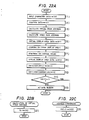
- Fig. 23 shows the memory space of VRAM used in a still further embodiment of a document processing system according to the present invention; and
- Fig. 24 is a flow chart illustrating the operation of VRAM shown in Fig. 23.
- Fig. 1 is a block diagram illustrating the structure of an embodiment of a document processing system according to the present invention. A
keyboard 1 is constructed of a character key unit from which a character code is input and a control command key unit from which control information necessary for printing is input. The input character code and control command are supplied toCPU 4. Aprinter 2 is used for printing an input character at a desired position. Abuzzer 3 is used for generating an alarm sound when an input character is superposed upon an already input character and when an erroneous input is effected from thekeyboard 1, to thereby notify the operator of such effect.CPU 4 controls peripheral devices such as thekeyboard 1 andprinter 2 in accordance with a control program stored inROM 6 and by using work areas ofRAM 7 described later.CGROM 5 functions as a character pattern memory and stores, at predetermined addresses, character patterns (e.g., constructed of 8 × 8 dot matrix) which are in one-to-one correspondence with character codes input from thekeyboard 1.ROM 6 stores control programs (including those programs for the steps of the procedure shown in the flow charts described later) to be executed byCPU 4, and associated data. A video RAM (VRAM) 8 functions as a display pattern memory and has a display space in one-to-one correspondence with the printable area of theprinter 2. The character pattern developed onVRAM 8 is displayed on adisplay unit 9 in the form of dot patterns. -
CPU 4 which operates as superposition judgement means and indication means of this invention, judges a superposition between a character pattern of a character code read out ofCGROM 5 and stored inVRAM 8 and a character pattern of a character code input from thekeyboard 1 and designated with a print position, in accordance with a predetermined arithmetic operation. If the already input and newly input character patterns are decided, based on the judgement result, to be superposed, then the superposed part of one pattern upon another is displayed distinguishably from the remainder to notify the operator of such effect by means of thebuzzer 3. - Figs. 2A and 2B are a perspective view and a plan view exemplarily showing the document process ing system of this invention, wherein similar elements to those in Fig. 1 are represented by using identical reference numerals.
- In Fig. 2B, a character
key unit 1a is constructed of character keys with which character codes are input. A control commandkey unit 1b is constructed of cursor keys and the like with which control information necessary for document edition and printing is input. - Fig. 3A shows an example of a display on the
display unit 9 shown in Fig. 1, whereincharacter patterns 9a to 9c (representative of characters A to C) are displayed on thedisplay unit 9 at predetermined areas. - Fig. 3B is an enlarged view of the character patterns shown in Fig. 3A, wherein identical reference characters and numerals are used to represent corresponding elements. As seen from Fig. 3B, each
character pattern 9a to 9c is constructed of 8 × 8 dot matrix, by way of example. - Fig. 4 illustrates the memory space of
VRAM 8 shown in Fig. 1, the memory space having 8 × n (n is an integer) addresses. As seen from Fig. 4, dot patterns which can be displayed on thedisplay unit 9 are stored in the memory space ofVRAM 8 from address "0" to address "n-1". For instance, in order to display the character patterns shown in Fig. 3B on thedisplay unit 9, values "00", "78", "0E", "09", "09", "0E", "78" and "00" in hexa decimal notation shown in Fig. 5 are stored inVRAM 8 from address "0" to address "7". - The operation of the document processing system shown in Fig. 1 will be described next.
- Character data input from the
keyboard 1 are sequentially stored in a work area TXT (text store area) ofRAM 7, and the associated print position information determined by an input from thekeyboard 1 and stored as the content of a work area XP (store area for print start position information in the x-direction) ofRAM 7 are also sequentially stored in work area TXT. Each time a character is stored,CPU 4 executes the control program stored inROM 6 in the following manner. The contents ofCGROM 5 are displayed on thedisplay unit 9 at the positions corresponding to addresses ofVRAM 8 while performing a logical OR operation (Exclusive-OR operation), the addresses corresponding to the associated character print positions on a printing medium. Thus, thedisplay unit 9 displays a superposed portion of an input character pattern, visually distinguishable from the other displayed character patterns, e.g., by means of blanked portion, inverted portion, flashed portion or a combination thereof. - In particular, in accordance with the program in
ROM 6,CPU 4 first saves a part of the contents ofVRAM 8 at the addresses corresponding to those subjected to an OR operation with the contents ofCGROM 5 on the display area ofVRAM 8, into a work area WV1 (store area for a first pattern) ofRAM 7. Then, the contents ofVRAM 8 with the newly input character written therein are stored in a work area WV2 (store area for a second pattern) and thereafter, the contents ofCGROM 5, WV1 and WV2 are subjected to an OR operation to judge if the newly input character pattern fromCGROM 5 intoVRAM 8 is superposed on the already input character pattern onVRAM 8. The resultant superposition judgement is then notified to the operator by means of thebuzzer 3. The operator notified of the character superposition then can adjust the print position to thereby enable to reduce misprints. - The operation for judging a superposition of an input character will be described with reference to Figs. 6A to 6E.
- It is first assumed that a character pattern "A" is already stored in
VRAM 8 as shown in Fig. 6A. Upon input of a new character "A" at a character print start position (Xp=4) in the x-direction ofVRAM 8 stored in work area XP ofRAM 7, the address VAD atVRAM 8 is calculated as "4" based on the value Xp of "4". Then, one display area of consecu tive eight bytes starting from the fourth byte ofVRAM 8 is read and the contents thereof in the form of dots are stored in work area WV1 as shown in Fig. 6B. Next, the pattern information (dot pattern of character "A") stored inCGROM 5 is stored intoVRAM 8 at addresses starting from the forth byte while performing an Exclusive-OR operation with the already loaded pattern, to accordingly obtain a pattern with the superposed portion between characters being blanked as shown in Fig. 6C. Similar to the above, one display area of consecutive eight bytes starting from the fourth byte of VRAM is read and the contents thereof in the form of dots are stored in work area WV2 as shown in Fig. 6D. Next, the character pattern stored in work area WV1 shown in Fig. 6B and a character pattern "A" read fromCGROM 5 are subjected to a logical OR operation under control ofCPU 4. The resultant character pattern as shown in Fig. 6E is stored in work area WV1, which pattern has the values "09", "7E", "7E", "09", "09", "0E", "78" and "00" in hexa decimal notation. This pattern does not coincide with the character pattern shown in Fig. 6B so thatCPU 4 recognizes an occurrence of a superposition between the already input and newly input character patterns and causes thebuzzer 3 to be actuated to notify the operator of such superposition. - Next, the superposition judgement procedure of this invention will be described with reference to Figs. 7A and 7B and Figs. 8A and 8B.
- Figs. 7A and 7B are truth tables for the OR and Exclusive-OR operations in the superposition judgement procedure, wherein A and B denotes an input and X denotes an output.
- Figs. 8A and 8B are flow charts illustrating the superposition judgement procedure of this invention, wherein (1) to (9) and (11) denotes a step of the procedure.
- First, character data input from the
keyboard 1 is stored in work area TXT of RAM 7 (step 1), and print position data (display position information) Xp is stored in work area TXT of RAM 7 (step 2). Then, the address atVRAM 8 corresponding to a print position is calculated in accordance with the flow shown in Fig. 8B (step 3). The calculated address VAD atVRAM 8 is used as a reference address to copy data within a character display area, i.e., within a region of 8 × 8 dots in row and column, into work area WV1 (step 4). Thereafter, the pattern information of a character to be displayed is read fromCGROM 5 and subjected to an Exclusive-OR operation with the already inputted character pattern on the display area ofVRAM 8 to display the operation result (step 5). This operation corresponds to an operation of setting the contents in the display area ofVRAM 8 as input A of Fig. 7B and the character pattern "A" fromCGROM 5 as input B, performing an Exclusive-OR operation between both the character patterns, and transferring output X to the display area ofVRAM 8. - Then, the data in the display area of
VRAM 8 are copied into work area WV2 (step 6). Thereafter, a logical OR operation is performed between the contents of work area WV1 and the character pattern "A" read fromCGROM 5 to write the result into work area WV1 (step 7). This operation corresponds to an operation of setting the contents of work area WV1 as input A of Fig. 7A and the character pattern "A" read fromCGROM 5 as input B, performing an OR operation therebetween, and transferring output X into work area WV1. Next, it is judged if the contents of work area WV1 corresponding to the display area completely coincide with the contents of work area WV2 (step 8). If YES, it is judged there is no contention (superposition) between character patterns to terminate the judgement procedure. If NO, thebuzzer 3 is actuated to notify the operator of the fact that the newly input character becomes superposed upon the already input character to thereafter terminate the judgement procedure (step 9). - In the
above step 3, the flow shown in Fig. 8B is executed. Since this embodiment employs thedisplay unit 9 constructed of one line, the display position information Xp is converted into the address VAD at VRAM 8 (step 11) to followstep 4 and succeeding steps. - Another embodiment of the present invention will be described next with reference to Fig. 1.
- Character data input from the
keyboard 1 are sequentially stored in a work area TXT (text store area) ofRAM 7, and the associated print position information determined by an input from thekeyboard 1 and stored as the content of a work area XP (store area for print start position information in the x-direction) ofRAM 7 are also sequentially stored in work area TXT. Each time a character is stored,CPU 4 executes the control program stored inROM 6 in the following manner. The contents ofCGROM 5 are displayed on thedisplay unit 9 at the positions corresponding to addresses ofVRAM 8 while performing a logical OR operation, the addresses corresponding to the associated character print positions on a printing medium. Thus, thedisplay unit 9 displays a superposed portion of an input character pattern, visually distinguishable from the other displayed character patterns. - In particular, in accordance with the program in
ROM 6,CPU 4 first saves a part of the contents ofVRAM 8 at the addresses corresponding to those subjected to an OR operation with the contents ofCGROM 5 on the display area ofVRAM 8, into a work area WV1 (store area for a first pattern) ofRAM 7. Then, the contents ofVRAM 8 with the newly input character written therein are stored in a work area WV2 (store area for a second pattern) and thereafter, the contents ofCGROM 5, WV1 and WV2 are subjected to an OR operation to judge if the newly input character pattern fromCGROM 5 intoVRAM 8 is superposed on the already input character pattern onVRAM 8. The resultant superposition judgement is then notified to the operator by means of thebuzzer 3. The operator notified of the character superposition then can adjust the print position to thereby enable to reduce misprints. - The operation for judging a superposition of an input character will be described with reference to Figs. 9A to 9F, wherein identical reference numeral is used to represent a similar element to that shown in Fig. 1.
- It is first assumed that a character pattern "A" is already stored in
VRAM 8 as shown in Fig. 9A. Upon input of a new character "A" at a character print start position (Xp=4) in the x-direction ofVRAM 8 stored in work area XP ofRAM 7, the address VAD atVRAM 8 is calculated as "4" based on the value Xp of "4". Then, one display area of consecutive eight bytes starting from the fourth byte ofVRAM 8 is read and the contents thereof in the form of dots are stored in work area WV1 as shown in Fig. 9B. Next, the pattern information (dot pattern of character "A") stored inCGROM 5 is stored intoVRAM 8 at addresses starting from the forth byte while performing an OR operation with the already loaded pattern, to accordingly obtain a pattern as shown in Fig. 9C. Similar to the above, one display area of consecutive eight bytes starting from the fourth byte of VRAM is read and the contents thereof in the form of dots are stored in work area WV2 as shown in Fig. 9D. Next, the character pattern stored in work area WV1 shown in Fig. 9B and a character pattern of Fig. 9D stored in work area WV2 are subjected to an Exclusive-OR operation under control ofCPU 4. The resultant character pattern as shown in Fig. 9E is stored in work area WV2. After a logical Exclusive-OR operation under control of CPU between the character pattern stored in work area WV2 and that read fromCGROM 5, a character pattern as shown in Fig. 9F is obtained and stored in work area WV2. The pattern has the values "00", "08", "08", "00", "00", "00", "00" and "00" in hexa decimal notation. All the values are not "0" so thatCPU 4 recognizes an occurrence of a superposition between the already input and newly input character patterns and causes thebuzzer 3 to be actuated to notify the operator of such superposition. - Next, the superposition judgement procedure of this invention will be described with reference to Figs. 10A and 10B and Figs. 11A and 11B.
- Figs. 10A and 10B are truth tables for the OR and Exclusive-OR operations in the superposition judgement procedure, wherein A and B denotes an input and X denotes an output.
- Figs. 11A and 11B are flow charts illustrating the superposition judgement procedure of this invention, wherein (1) to (9) and (11) denote a step of the procedure.
- First, character data inputted from the
keyboard 1 is stored in work area TXT of RAM 7 (step 1), and print position data (display position information) Xp is stored in work area TXT of RAM 7 (step 2). Then, the address atVRAM 8 corresponding to a print position is calculated in accordance with the flow shown in Fig. 11B (step 3). The calculated address VAD atVRAM 8 is used as a reference address to copy data within a character display area, i.e., within a region of 8 × 8 dots in row and column, into work area WV1 (step 4). Thereafter, the pattern information of a character to be displayed is read fromCGROM 5 and subjected to an OR operation with the already input character pattern on the display area ofVRAM 8 to display the operation result (step 5). This operation corresponds to an operation of setting the contents in the display area ofVRAM 8 as input A of Fig. 10A and the character pattern "A" fromCGROM 5 as input B, performing an OR operation between both the character patterns, and transferring output X to the display area ofVRAM 8. - Then, the data in the display area of
VRAM 8 are copied into work area WV2 (step 6). Thereafter, a logical Exclusive-OR operation is performed between the contents of work area WV1 and work area WV2 to write the result into work area WV2 (step 7). This operation corresponds to an operation of setting the contents of work area WV2 as input A of Fig. 10B and the contents of work area WV1 as input B, performing an Exclusive-OR operation therebetween, and transferring output X into work area WV2. - Next, a logical Exclusive-OR operation is performed between the contents of work area WV2 and the newly input character pattern read from
CGROM 5 to write the result into work area WV2 (step 8). If YES, it is judged there is no contention (superposition) between character patterns to terminate the judgement procedure. If NO, thebuzzer 3 is actuated to notify the operator of the fact that the newly input character becomes superposed upon the already input character to thereafter terminate the judgement procedure (step 10). - In the
above step 3, the flow shown in Fig. 11B is executed. Since this embodiment employs thedisplay unit 9 constructed of one line, the display position information Xp is converted into the address VAD at VRAM 8 (step 11) to followstep 4 and succeeding steps. - The above embodiment has been described using the
display unit 9 constructed of a matrix of 8 × n dots in row and column. However, the invention is also applicable to the display unit constructed of a matrix of (m × 8) × n dots in row and column. - Fig. 12 shows the memory space of VRAM used in another embodiment of the document processing system according to the present invention, the memory space being constructed of, e.g., a matrix of (m × 8) × n dots in row and column.
- Fig. 13 is a flow chart illustrating the procedure of calculating the address of VRAM having the memory space shown in Fig. 12, wherein (31) to (33) represent a step of the procedure and correspond to step 3 of the flow chart shown in Fig. 8A or Fig. 11A, or
step 3 of the flow chart shown in Fig. 8B or Fig. 11B. - When a print position in row is input from the
keyboard 1, the row position information is stored in a work area YP ofRAM 7. - Then, at
step 3 of the flow chart shown in Fig. 8A or Fig. 11A or in Fig. 8B or Fig. 11B, the contents of work area YP are divided by the number of unit dots in row, i.e., "8" to write the integer of quotient in a work area YINT (step 31). The remainder of division of the contents of work area YP by "8" is stored in work area YMOD (step 32). Next,CPU 4 sets a value as the address VAD ofVRAM 8, the value being that obtained by multiplying the contents of work area YINT by n and by adding thereto the display position information Xp (step 33). - Fig. 14 is a flow chart illustrating a read control procedure of VRAM, wherein (41) to (46) represent a step of the procedure and correspond to step 4 of the flow chart shown in Fig. 8A or Fig. 11A.
- The contents of work area VAD are added with n (the total number of dots in column) to store the added result in work area VAD 2 (step 41). The contents of
work area VAD 2 is multiplied by 256 and added with the contents of work area VAD to write the result in work area DAT (step 42). Next, it is judged if the contents of work area YMOD stored atstep 32 of the flow chart shown in Fig. 13 are "0" or not. If NO, the contents of work area DAT are divided by "2" to store the integer of division into work area DAT (step 44). After the contents of work area YMOD is subtracted by "1" (step 45), the flow returns to step 43. - Alternatively, if YES at
step 43, the contents of work area DAT are divided by "256" to store the remainder of division into work area DAT (step 46) to terminate the read control procedure and advance to step 5 of the flow chart shown in Fig. 8A or Fig. 11A. - Fig. 15 is a flow chart illustrating the control procedure of OR display in VRAM, wherein (51) to (58) represent a step of the procedure and correspond to step 5 of the flow chart shown in Fig. 8A or Fig. 11A.
- First, it is judged if the contents of work area YMOD are "0" or not (step 51). If NO, the contents of work area DAT are multiplied by 2 to store the result in work area DAT (step 52). After the contents of work area YMOD are subtracted by "1" (step 53), the flow returns to step 51.
- Alternatively, if YES at
judgement step 51, the contents of work area DAT are divided by "256" to store the remainder of division into work area DAT 1 (step 54), and store the integer of division into work area DAT 2 (step 55). Next, the contents of work area VAD are added with the total number n of dots in column to store the added result in work area VAD 2 (step 56). Next, an OR operation is performed between the contents of work area VAD andwork area VAT 1 to store the operation result in work area VAD (step 57). Also, an OR operation is performed between the contents ofwork area VAD 2 andwork area DAT 2 to store the operation result in work area VAD 2 (step 58). Then the flow advances to step 6 shown in Fig. 11A orstep 7 shown in Fig. 13A, respectively following the succeeding steps. - Therefore, assuming that character patterns as shown in Fig. 16 are stored in VRAM 8 (wherein print position information Xp is "2", the contents of work area YP are "1", and the total number n of dots in column is "2"), the value of the work area YINT becomes "0", that of work area YMOD "1", and that of work area VAD "2".
- Since the value of
work area VAD 2 becomes "962" and that of work area DAT becomes "0F3B" in hexa decimal, the result injudgement step 43 does not become "0". Therefore, the value of work area injudgement step 44 becomes "079D" in hexa decimal, the value of work area YMOD instep 45 becomes "0" and the value of work area DAT becomes "9D" in hexa decimal so that objective one byte can be read. - In case where the value "02" in hexa decimal of work area DAT is OR-displayed in VRAM, since the value of work area YMOD is not "0", the value of work area DAT becomes "04" in hexa decimal at
step 52, the value of work area YMOD "0" instep 53, the value ofwork area DAT 1 "00" in hexa decimal atnext step 54, the value ofwork area DAT 2 "04" in hexa decimal atstep 55, the value ofwork area VAD 2 "962" atstep 56, the value of work area VAD "3F" in hexa decimal instep 57, and the value ofwork area VAD 2 "0F" in hexa decimal atstep 58 which is OR-displayed inVRAM 8. - As described so far, the document processing system of this invention comprises a display pattern memory having an address space in one-to-one correspondence with a printable area of a printing unit; a display unit for displaying character pattern dot information stored in said display pattern memory; superposition judgement means for judging based on a predetermined operation a superposition between a character pattern of a character code read from said character pattern memory and stored in said display pattern memory and a character pattern to be sequentially input while a character print position is designated, and indication means for indicating the judgement result by said superposition judgement means. Therefore, various advantages can be enjoyed. Namely, an input text information can be displayed in just the same way as it is actually printed out. A superposed portion of an input character pattern can be displayed distinguishably from the other character dot patterns already input, at the time when the new character is input. A superposed portion can be visually identified for the purpose of avoiding character superposition and a desired character pattern can be entered readily by the operator at a desired position.
- Fig. 18 is a block diagram illustrating the structure of an embodiment of a document processing system according to the present invention. A
keyboard 1 is constructed of a character key unit from which a character code is input and a control command key unit from which control information necessary for printing is input. The inputted character code and control command are supplied toCPU 4. Aprinter 2 is used for printing an input character at a desired position. Abuzzer 3 which operates as indication means of this invention, is used for generating an alarm sound when an input character is superposed upon an already input character and when an erroneous input is effected from thekeyboard 1, to thereby notify the operator of such effect.CPU 4 controls peripheral devices such as thekeyboard 1 andprinter 2 in accordance with a control program stored inROM 6 and by using work areas ofRAM 7 described later.CGROM 5 functions as a character pattern memory and stores, at predetermined addresses, character patterns (e.g., constructed of 8 × 8 dot matrix) which are in one-to-one correspondence with character codes input from thekeyboard 1.ROM 6 stores control programs (including those programs for the steps of the procedure shown in the flow charts described later) to be executed byCPU 4, and associated data. A video RAM (VRAM) 8 functions as a display pattern memory and has a display space in one-to-one correspondence with the printable area of theprinter 2. The character pattern developed onVRAM 8 is displayed on adisplay unit 9 in the form of dot patterns. A font ROM (FONTROM) 10 operates as judgement-reference character pattern store means of this invention, and stores judgement-reference character patterns (to be described later) corresponding to character patterns stored inCGROM 5 ordisplay pattern memory 5. Avirtual VRAM 11 operates as judgement-reference character pattern store means of this invention, and stores judgement-reference character patterns corresponding to display character patterns read fromCGROM 5 and having their addresses corresponding to those ofVRAM 8. -
CPU 4 which operates as superposition judgement means of this invention, judges a superposition between judgement-reference character patterns sequentially read fromFONTROM 10 and stored invirtual VRAM 11, in accordance with a predetermined arithmetic operation. In this case, display character patterns are stored inVRAM 8 simultaneously with storing judgement-reference character patterns. The judgement result is distinguishably displayed on thedisplay unit 9 and thebuzzer 3 is actuated to notify the operator of such effect.FONTROM 10 is constructed of a dot matrix larger in size than that ofCGROM 5 in order to have an enlarged and more detailed font image than that ofCGROM 5. Similarly,virtual VRAM 11 used for storing character patterns of FONTROM 10 therein has a larger memory space, e.g., 16 × 16 dots per one judgement-reference character pattern in this embodiment. The address processing is conducted in a similar manner to that ofVRAM 8. - The operation of the document processing system shown in Fig. 18 will be described next.
- Character data input from the
keyboard 1 are sequentially stored in a work area TXT (text store area) ofRAM 7, and the associated print position information determined by an input from thekeyboard 1 and stored as the content of a work area XP (store area for print start position information in the x-direction) ofRAM 7 are also sequentially stored in work area TXT. Each time a character is stored,CPU 4 executes the control program stored inROM 6 in the following manner. The contents ofCGROM 5 are displayed on thedisplay unit 9 at the positions corresponding to addresses ofVRAM 8 while performing a logical OR operation, the addresses corresponding to the associated character print positions on a printing medium. Thus, thedisplay unit 9 visually displays the OR operation result. Simultaneously with displaying character patterns,CPU 4 causes a judgement-reference character pattern corresponding to a character pattern read fromCGROM 5 to be read fromFONTROM 10 and written it invirtual VRAM 11 at addresses corresponding to those ofRAM 8 while performing an Exclusive-OR operation or an OR operation. By this Exclusive-OR operation, a superposed portion of judgement-reference character patterns onvirtual VRAM 11 can be displayed distinguishably from the remainder on thedisplay unit 9. Further, a superposition judgement between judgement-reference character patterns can be effected by the logical OR operation. - Next, the operation for judging a superposition of an input character according to this invention will be described with reference to Figs. 19A and 19B wherein similar elements to those shown in Fig. 18 are represented by using identical reference numerals.
- As seen from the figures, the size of a judgement-reference character pattern stored in
FONTROM 10 is constructed of a matrix of 16 × 16 dots in this embodiment, which is two times larger than the matrix size shown in Fig. 3B. The size ofvirtual VRAM 11 for storing a judgement-reference character pattern as shown in Fig. 19A is correspondingly constructed such that the number of dots in row is twice as large as the memory space ofVRAM 8 shown in Fig. 4 to thereby develop a judgement-reference character pattern in the area from the 0-th byte to (2n-1)-th byte thereof. - In accordance with the control program in
ROM 6,CPU 4 first saves a part of the contents ofvirtual VRAM 11 at the addresses corresponding to those subjected to a logical operation with the contents of FONTROM 10 on the display area ofvirtual VRAM 11, into a work area WV1 ofRAM 7. Then, the contents ofvirtual VRAM 11 with the newly input judgement-reference character pattern written therein are stored in a work area WV2 and thereafter, the contents ofFONTROM 10, WV1 and WV2 are subjected to a predetermined logical operation to enable to judge if the newly input judgement-reference character pattern fromFONTROM 10 intovirtual VRAM 11 is superposed on the already input judgement-reference character pattern onvirtual VRAM 11. Although the dissolving power ofvirtual VRAM 11 is different from that ofVRAM 8, a superposition onvirtual VRAM 11 is equivalent to those on thedisplay unit 9 andVRAM 8. The judgement result is notified by means of thebuzzer 3. Thus, irrespective of a physical dissolving power of thedisplay unit 9, a superposition of a character pattern input from thekeyboard 1 can be automatically notified. In addition, the superposed portion can be displayed on thedisplay unit 9 distinguishably from the remaining dot patterns, e.g., by means of a blanked portion, so that the operator can recognize it and adjust the print position to thereby enable to reduce misprints. - The operation for judging a superposition of an input character according to this invention will be described with reference to Figs. 20A and 20B and Figs. 21A and 21B.
- Figs. 20A and 20B are truth tables for the OR and Exclusive-OR operations in the superposition judgement procedure, wherein A and B denotes an input and X denotes an output.
- Figs. 21A to 21C are flow charts illustrating the superposition judgement procedure of this invention, wherein (1) to (11), (21) and (31) denote a step of the procedure.
- First, character data input from the
keyboard 1 is stored in work area TXT of RAM 7 (step 1), and print position data (display position information) Xp is stored in work area TXT of RAM 7 (step 2). Then, the address atvirtual VRAM 11 corresponding to a print position is calculated in accordance with the flow shown in Fig. 21B (step 3), and the address atVRAM 8 corresponding to a print position is calculated in accordance with the flow shown in Fig. 21C (step 4). The calculated address VAD atVRAM 8 is used as a reference address to copy data within a judgement-reference character display area ofvirtual VRAM 11, i.e., within a region of 16 × 16 dots in row and column, into work area WV1 (step 5). Thereafter, the pattern information of a character to be displayed (display character pattern) is read fromCGROM 5 and subjected to an Exclusive-OR operation with the already input character pattern on the display area ofVRAM 8 to display the operation result (step 6). Simultaneously with reading the display character pattern, a judgement-reference character pattern read fromFONTROM 10 is subjected to an Exclusive-OR operation and written in virtual VRAM 11 (step 7). This operation corresponds to an operation of setting the display character pattern read fromCGROM 5 as input A of Fig. 20A and the contents ofVRAM 8 in the display area as input B, performing an Exclusive-OR operation therebetween, and transferring output X to the display area ofVRAM 8. - Then, the data in the display area of
virtual VRAM 11 are copied into work area WV2 (step 8). Thereafter, a logical OR operation is performed between the contents of work area WV1 and work area WV2 (step 9). This operation corresponds to an operation of setting the contents of work area WV1 as input A of Fig. 20A and the contents of work area WV2 as input B, performing an OR operation therebetween, and transferring output X into work area WV2. - Next, it is judged if the contents of work areas WV1 and WV2 coincide with each other (step 10). If YES, the judgement procedure is terminated. If NO, it is judged that the already and newly written judgement-reference character patterns are superposed so that the
buzzer 3 is actuated to notify the operator of such effect (step 11). - In the
above step 3, the flow shown in Fig. 21B is executed. Since this embodiment employs thedisplay unit 9 constructed of one line, the display position information Xp is converted into the address VAD at VRAM 8 (step 21) to followstep 4 and succeeding steps. - In the
above step 4, the flow shown in Fig. 21C is executed. In this embodiment, the address can be obtained by dividing the contents of work area VAD by "2" which is a ratio of 16 dots in column of FONTROM 10 to 8 dots in column of the display unit 9 (step 31). - The above embodiment has been described using the
display unit 9 constructed of a matrix of 8 × n dots in row and column. However, the invention is also applicable to the display unit constructed of a matrix of (m × 8) × n dots in row and column. - Figs. 22A to 22C are flow charts illustrating the superposition judgement procedure of this invention, wherein (1) to (11), (21) and (31) denote a step of the procedure.
- First, character data inputted from the
keyboard 1 is stored in work area TXT of RAM 7 (step 1), and print position data (display position information) Xp is stored in work area TXT of RAM 7 (step 2). Then, the address atvirtual VRAM 11 corresponding to a print position is calculated in accordance with the flow shown in Fig. 22B (step 3), and the address atVRAM 8 corresponding to a print position is calculated in accordance with the flow shown in Fig. 22C (step 4). The calculated address VAD atVRAM 8 is used as a reference address to copy data within a judgement-reference character display area ofvirtual VRAM 11, i.e., within a region of 16 × 16 dots in row and column, into work area WV1 (step 5). Thereafter, the pattern information of a character to be displayed (display character pattern) is read fromCGROM 5 and subjected to an Exclusive-OR operation with the already input character pattern on the display area ofVRAM 8 to display the operation result (step 6). Simultaneously with reading the display character pattern, a judgement-reference character pattern read fromFONTROM 10 is subjected to an Exclusive-OR operation and written in virtual VRAM 11 (step 7). This operation corresponds to an operation of setting the display character pattern read fromCGROM 5 as input A of Fig. 20A and the contents ofVRAM 8 in the display area as input B, performing an OR operation therebetween, and transferring output X to the display area ofVRAM 8. - Then, the data in the display area of
virtual VRAM 11 are copied into work area WV2 (step 8). Thereafter, a logical Exclusive-OR operation is performed between the contents of work area WV1 and work area WV2 (step 9). This operation corresponds to an operation of setting the contents of work area WV1 as input A of Fig. 20A and the contents of work area WV2 as input B, performing an OR operation therebetween, and transferring output X into work area WV2. - Next, an Exclusive-OR operation is performed between the contents of work area WV2 and the character patter read from
CGROM 5 to write the operation result into work area WV2 (step 10). Next, it is judged if the contents of work area WV2 are all "0" (step 11). If YES, the judgement procedure is terminated. If NO, it is judged that the already and newly written judgement-reference character patterns are superposed so that thebuzzer 3 is actuated to notify the operator of such effect (step 11). - In the
above step 3, the flow shown in Fig. 22B is executed. Since this embodiment employs thedisplay unit 9 constructed of one line, the display position information Xp is converted into the address VAD at VRAM 8 (step 21) to followstep 4 and succeeding steps. - In the
above step 4, the flow shown in Fig. 22C is executed. In this embodiment, the address can be obtained by dividing th contents of work area VAD by "2" which is a ratio of 16 dots in column of FONTROM 10 to 8 dots in column of the display unit 9 (step 31). - Fig. 23 shows the memory space of VRAM used in another embodiment of the document processing system according to the present invention, the memory space being constructed of, e.g. a matrix of (m × 8) × n dots in row and column.
- Fig. 24 is a flow chart illustrating the procedure of calculating the address of VRAM having the memory space shown in Fig. 23, wherein (41) to (43) represent a step of the procedure and correspond to step 3 of the flow chart shown in Fig. 21A or Fig. 22A.
- When a print position in row is input from the
keyboard 1, the row position information is stored in a work area YP ofRAM 7 whereas the position onvirtual VRAM 11 is stored in work areas VAD and YMOD. - Then, at
step 3 of the flow chart shown in Fig. 21A or Fig. 22A, the contents of work area YP are divided by the number of unit dots in row, i.e., "16" (corresponding to the number of unit dots in row of FONTROM 10) to write the integer of quotient in a work area YINT (step 41). The remainder of division of the contents of work area YP by "16" is stored in work area YMOD (step 42). Next,CPU 4 sets a value as the address VAD ofVRAM 8, the value being that obtained by multiplying the contents of work area YINT by n (corresponding to the total number of dots in column of virtual VRAM 11) and by adding thereto the display position information Xp (step 33). Thereafter, the above steps are repeated each timevirtual VRAM 11 is accessed whereby using the calculated address VAD as a reference, the contents of address adjacent thereto is shifted by the value of work area YMOD to thereby effect a virtual display at a desired position in row. Thus, the present invention can be applied also to a combination of virtual VRAM with a dissolving power of (m × 16) in row and a display unit with a lower dissolving power. - As described so far, the document processing system of this invention comprises a display pattern memory having an address space in one-to-one correspondence with a printable area of a printing unit; a display unit for displaying character pattern dot information stored in said display pattern memory; judgement-reference character pattern store means for storing a judgement-reference character pattern corresponding to a character pattern stored in said display pattern memory; read-out judgement-reference character pattern store means for storing a judgement-reference character pattern corresponding to a display character pattern read from said display pattern memory, at an address corresponding to that of said display pattern memory; superposition judgement means for judging, based on a predetermined operation and in parallel with development of a character pattern into said display pattern memory, a superposition between judgement-reference character patterns read from said judgement-reference character pattern store means and written in said read-out judgement-reference character pattern store means; and indication means for indicating the judgement result by said superposition judgement means. Therefore, various advantages can be enjoyed. Namely, an input text information can be displayed in just the same way as it is actually printed out. If a character pattern which causes a superposition is designated, the superposed portion of the input character pattern can be displayed clearly and distinguishably from the other character dot patterns already input, at the time when the new character is input. Therefore, the operator can adjust again the print position at an optimum position prior to printing. Therefore, characters can be effectively input while maintaining a good printing appearance without misprints.
Claims (7)
a display pattern memory having an address space in one-to-one correspondence with a printable area of a printing unit;
a display unit for displaying character pattern dot information stored in said display pattern memory;
judgement-reference character pattern store means for storing a judgement-reference character pattern corresponding to a character pattern stored in said display pattern memory;
read-out judgement-reference character pattern store means for storing a judgement-reference character pattern corresponding to a display character pattern read from said display pattern memory, at an address corresponding to that of said display pattern memory;
superposition judgement means for judging, based on a predetermined operation and in parallel with development of a character pattern into said display pattern memory, a superposition between judgement-reference character patterns read from said judgement-reference character pattern store means and written in said read-out judgement-reference character pattern store means; and
indication means for indicating the judgement result by said superposition judgement means.
a display pattern memory having an address space in one-to-one correspondence with a printable area of a printing unit;
a display unit for displaying character pattern dot information stored in said display pattern memory;
superposition judgement means for judging based on a predetermined operation a superposition between a character pattern of a character code read from said character pattern memory and stored in said display pattern memory and a character pattern to be sequentially input while a character print position is designated; and
indication means for indicating the judgement result by said superposition judgement means.
Applications Claiming Priority (4)
| Application Number | Priority Date | Filing Date | Title |
|---|---|---|---|
| JP62065691A JPS63233852A (en) | 1987-03-23 | 1987-03-23 | Document processor |
| JP65691/87 | 1987-03-23 | ||
| JP65690/87 | 1987-03-23 | ||
| JP62065690A JPS63233851A (en) | 1987-03-23 | 1987-03-23 | Document processor |
Publications (3)
| Publication Number | Publication Date |
|---|---|
| EP0284312A2 true EP0284312A2 (en) | 1988-09-28 |
| EP0284312A3 EP0284312A3 (en) | 1989-10-04 |
| EP0284312B1 EP0284312B1 (en) | 1993-11-03 |
Family
ID=26406824
Family Applications (1)
| Application Number | Title | Priority Date | Filing Date |
|---|---|---|---|
| EP88302422A Expired - Lifetime EP0284312B1 (en) | 1987-03-23 | 1988-03-18 | Document processing system |
Country Status (3)
| Country | Link |
|---|---|
| US (1) | US4947343A (en) |
| EP (1) | EP0284312B1 (en) |
| DE (1) | DE3885324T2 (en) |
Families Citing this family (10)
| Publication number | Priority date | Publication date | Assignee | Title |
|---|---|---|---|---|
| US5276795A (en) * | 1989-03-15 | 1994-01-04 | Sun Microsystems, Inc. | Method and apparatus for selecting and executing defaults in a window based display system |
| US5135437A (en) | 1989-11-13 | 1992-08-04 | Schubert Keith E | Form for making two-sided carbonless copies of information entered on both sides of an original sheet and methods of making and using same |
| US5137494A (en) | 1989-11-13 | 1992-08-11 | Schubert Keith E | Two-sided forms and methods of laying out, printing and filling out same |
| US5154668A (en) | 1989-04-06 | 1992-10-13 | Schubert Keith E | Single paper sheet forming a two-sided copy of information entered on both sides thereof |
| US5248279A (en) | 1989-04-06 | 1993-09-28 | Linden Gerald E | Two-sided, self-replicating forms |
| US5224897A (en) | 1989-04-06 | 1993-07-06 | Linden Gerald E | Self-replicating duplex forms |
| US5395288A (en) | 1989-04-06 | 1995-03-07 | Linden; Gerald E. | Two-way-write type, single sheet, self-replicating forms |
| US5127879A (en) | 1989-04-06 | 1992-07-07 | Schubert Keith E | Apparatus for recordkeeping |
| US5235679A (en) * | 1989-06-14 | 1993-08-10 | Hitachi, Ltd. | Guidance method and apparatus upon a computer system |
| US6280322B1 (en) | 1989-11-13 | 2001-08-28 | Gerald E. Linden | Single sheet of paper for duplicating information entered on both surfaces thereof |
Citations (2)
| Publication number | Priority date | Publication date | Assignee | Title |
|---|---|---|---|---|
| US4323315A (en) * | 1979-02-09 | 1982-04-06 | Ing. C. Olivetti & C., S.P.A. | Electronic typewriter with display device |
| DE3042145A1 (en) * | 1980-11-08 | 1982-06-16 | Olympia Werke Ag, 2940 Wilhelmshaven | Correction control in word processors - using multi-digit line display to allow section of text. to be corrected prior to printing |
Family Cites Families (3)
| Publication number | Priority date | Publication date | Assignee | Title |
|---|---|---|---|---|
| JPS60124257A (en) * | 1983-12-08 | 1985-07-03 | Ricoh Co Ltd | Signal processor |
| JPS60183628A (en) * | 1984-03-01 | 1985-09-19 | Minolta Camera Co Ltd | Character signal generator |
| US4694405A (en) * | 1985-07-09 | 1987-09-15 | Office Automation Systems, Inc. | Laser printer controller data alignment device |
-
1988
- 1988-03-18 EP EP88302422A patent/EP0284312B1/en not_active Expired - Lifetime
- 1988-03-18 DE DE88302422T patent/DE3885324T2/en not_active Expired - Fee Related
-
1989
- 1989-12-11 US US07/449,322 patent/US4947343A/en not_active Expired - Lifetime
Patent Citations (2)
| Publication number | Priority date | Publication date | Assignee | Title |
|---|---|---|---|---|
| US4323315A (en) * | 1979-02-09 | 1982-04-06 | Ing. C. Olivetti & C., S.P.A. | Electronic typewriter with display device |
| DE3042145A1 (en) * | 1980-11-08 | 1982-06-16 | Olympia Werke Ag, 2940 Wilhelmshaven | Correction control in word processors - using multi-digit line display to allow section of text. to be corrected prior to printing |
Also Published As
| Publication number | Publication date |
|---|---|
| EP0284312B1 (en) | 1993-11-03 |
| EP0284312A3 (en) | 1989-10-04 |
| DE3885324T2 (en) | 1994-03-24 |
| US4947343A (en) | 1990-08-07 |
| DE3885324D1 (en) | 1993-12-09 |
Similar Documents
| Publication | Publication Date | Title |
|---|---|---|
| US4078249A (en) | Digital display composition system | |
| EP0009536B1 (en) | Data entry apparatus with dual-mode tabbing function selectable from keyboard | |
| US4947343A (en) | Document processing system for detecting an overlap in two characters | |
| JP2913758B2 (en) | Document processing device | |
| JPH03229357A (en) | Layout display controller for document processor | |
| US5383730A (en) | Document processing apparatus that magnifies only black portions of characters | |
| JPH03229355A (en) | Layout display controller for document processor | |
| JPS62104785A (en) | Document processing apparatus | |
| JP2520908B2 (en) | Panel input device | |
| US4695172A (en) | Printer with display for double-width character | |
| EP0395090B1 (en) | Character pattern data generating device | |
| JP2879757B2 (en) | Printing equipment | |
| JPS5816380A (en) | Output device for displaying or recording figure pattern | |
| JP2610874B2 (en) | Information processing method | |
| JP2705690B2 (en) | Display control device | |
| JPS6132174A (en) | Electronic device | |
| JPS62121065A (en) | Character enlarging printer | |
| JP3077777B2 (en) | Document processing device | |
| JP2903516B2 (en) | Document processing device | |
| JP2768565B2 (en) | Character processor | |
| JPS6315287A (en) | Pattern generator | |
| JPS648852B2 (en) | ||
| JPS60159068A (en) | Output device | |
| JPH07106654B2 (en) | Information processing method | |
| JPH07114545A (en) | Word processor and method therefor |
Legal Events
| Date | Code | Title | Description |
|---|---|---|---|
| PUAI | Public reference made under article 153(3) epc to a published international application that has entered the european phase |
Free format text: ORIGINAL CODE: 0009012 |
|
| AK | Designated contracting states |
Kind code of ref document: A2 Designated state(s): DE FR GB IT |
|
| PUAL | Search report despatched |
Free format text: ORIGINAL CODE: 0009013 |
|
| AK | Designated contracting states |
Kind code of ref document: A3 Designated state(s): DE FR GB IT |
|
| 17P | Request for examination filed |
Effective date: 19900221 |
|
| 17Q | First examination report despatched |
Effective date: 19910618 |
|
| ITTA | It: last paid annual fee | ||
| GRAA | (expected) grant |
Free format text: ORIGINAL CODE: 0009210 |
|
| AK | Designated contracting states |
Kind code of ref document: B1 Designated state(s): DE FR GB IT |
|
| PG25 | Lapsed in a contracting state [announced via postgrant information from national office to epo] |
Ref country code: FR Effective date: 19931103 |
|
| REF | Corresponds to: |
Ref document number: 3885324 Country of ref document: DE Date of ref document: 19931209 |
|
| ITF | It: translation for a ep patent filed |
Owner name: SOCIETA' ITALIANA BREVETTI S.P.A. |
|
| PG25 | Lapsed in a contracting state [announced via postgrant information from national office to epo] |
Ref country code: GB Effective date: 19940318 |
|
| EN | Fr: translation not filed | ||
| PLBE | No opposition filed within time limit |
Free format text: ORIGINAL CODE: 0009261 |
|
| STAA | Information on the status of an ep patent application or granted ep patent |
Free format text: STATUS: NO OPPOSITION FILED WITHIN TIME LIMIT |
|
| 26N | No opposition filed | ||
| GBPC | Gb: european patent ceased through non-payment of renewal fee |
Effective date: 19940318 |
|
| PGFP | Annual fee paid to national office [announced via postgrant information from national office to epo] |
Ref country code: IT Payment date: 20060331 Year of fee payment: 19 |
|
| PGFP | Annual fee paid to national office [announced via postgrant information from national office to epo] |
Ref country code: DE Payment date: 20060518 Year of fee payment: 19 |
|
| PG25 | Lapsed in a contracting state [announced via postgrant information from national office to epo] |
Ref country code: DE Free format text: LAPSE BECAUSE OF NON-PAYMENT OF DUE FEES Effective date: 20071002 |
|
| PG25 | Lapsed in a contracting state [announced via postgrant information from national office to epo] |
Ref country code: IT Free format text: LAPSE BECAUSE OF NON-PAYMENT OF DUE FEES Effective date: 20070318 |