EP0284325A2 - Radio telephone - Google Patents
Radio telephone Download PDFInfo
- Publication number
- EP0284325A2 EP0284325A2 EP88302447A EP88302447A EP0284325A2 EP 0284325 A2 EP0284325 A2 EP 0284325A2 EP 88302447 A EP88302447 A EP 88302447A EP 88302447 A EP88302447 A EP 88302447A EP 0284325 A2 EP0284325 A2 EP 0284325A2
- Authority
- EP
- European Patent Office
- Prior art keywords
- base unit
- loudspeaker
- signal
- radio telephone
- telephone set
- Prior art date
- Legal status (The legal status is an assumption and is not a legal conclusion. Google has not performed a legal analysis and makes no representation as to the accuracy of the status listed.)
- Granted
Links
- 230000000694 effects Effects 0.000 claims description 2
- 238000001514 detection method Methods 0.000 claims 3
- 238000012544 monitoring process Methods 0.000 abstract description 3
- 238000004891 communication Methods 0.000 description 12
- 230000006854 communication Effects 0.000 description 12
- 230000000994 depressogenic effect Effects 0.000 description 4
- 238000012986 modification Methods 0.000 description 4
- 230000004048 modification Effects 0.000 description 4
- 238000010586 diagram Methods 0.000 description 3
- 230000005540 biological transmission Effects 0.000 description 2
- 230000005236 sound signal Effects 0.000 description 2
- 230000009977 dual effect Effects 0.000 description 1
- 230000001702 transmitter Effects 0.000 description 1
Images


Classifications
-
- H—ELECTRICITY
- H04—ELECTRIC COMMUNICATION TECHNIQUE
- H04M—TELEPHONIC COMMUNICATION
- H04M1/00—Substation equipment, e.g. for use by subscribers
- H04M1/60—Substation equipment, e.g. for use by subscribers including speech amplifiers
- H04M1/6033—Substation equipment, e.g. for use by subscribers including speech amplifiers for providing handsfree use or a loudspeaker mode in telephone sets
- H04M1/6041—Portable telephones adapted for handsfree use
-
- H—ELECTRICITY
- H04—ELECTRIC COMMUNICATION TECHNIQUE
- H04M—TELEPHONIC COMMUNICATION
- H04M1/00—Substation equipment, e.g. for use by subscribers
- H04M1/72—Mobile telephones; Cordless telephones, i.e. devices for establishing wireless links to base stations without route selection
- H04M1/725—Cordless telephones
- H04M1/72502—Cordless telephones with one base station connected to a single line
Definitions
- This invention relates to the field of radio telephones, typically cordless telephones and, more particularly, to means for increasing the sound volume in certain circumstances.
- Radio telephones are comprised of a radio telephone set and a base unit.
- the radio telephone set has a handset, and the base unit is connected to wired telephone lines for exchanging speech signals between the wired telephone lines and the radio telephone set through a radio channel.
- the base unit and the radio telephone set each have a transmitter and a receiver.
- the base unit When a call signal appears at a wired telephone line, the base unit transmits a paging signal to the radio telephone set through a predetermined control channel to set up a speech channel.
- the paging signal includes a channel signal to indicate one of a number of speech channels.
- the radio telephone set sends out a paging response signal through the control channel.
- the base unit detects the intensity of the received paging response signal sent from the radio telephone set, i.e. the intensity of the paging response signal on the control channel. Then, the base unit stops the transmission of the paging signal when the detected intensity exceeds a predetermined level, and switches the radio channel between the base unit and the radio telephone set from the control channel to the speech channel indicated in the paging signal.
- the radio telephone set also switches the radio channel from the paging channel to the speech channel set by the received paging signal. Thereafter, the base unit transmits a bell ringing signal to the radio telephone set via the speech channel. After transmitting the ringing signal, the base unit establishes a speech path between the wired telephone line and the radio telephone set when it receives an "off-hook" signal from the radio telephone set.
- the base unit When the base unit receives a call origination signal (an "off-hook" signal) from the radio telephone set through the control channel while it is in a waiting state, it detects the request from the radio telephone set to originate a call and transmits a response signal which includes a channel signal indicating one of a plurality of speech channels. The base unit then establishes a speech path between the wired telephone line and itself, and switches the radio channel from the control channel to the speech channel in response to the response signal. After receiving the response signal, the radio telephone set also switches the radio channel from the control channel to the speech channel in response to the received response signal.
- a call origination signal an "off-hook" signal
- the radio telephone set transmits dialing signals to the base unit through the speech channel by a dialing operation, the dialing signal is transmitted to the wired telephone line via the base unit.
- the radio telephone apparatus carries out the operations of receiving incoming telephone calls from the wired telephone line and originating calls from the radio telephone set.
- the main object of the present invention is therefore to provide a a radio telephone apparatus which is capable of producing speech signals from a loudspeaker.
- the present invention provides radio telephone apparatus comprising a base unit coupled to a wired telephone line, and a radio telephone set including a battery and coupled to the base unit through a radio channel characterized in that the base unit includes a loudspeaker) and mode selection means for selecting a loudspeaker mode, in which the loudspeaker is connected to the wired telephone line.
- the radio telephone apparatus has a base unit and a radio telephone set, the base unit being coupled to a wired telephone line and connected to the radio telephone set through a radio channel.
- the base unit operates by DC power converted from an AC source, while the radio telephone set is powered by a small storage battery, which may be charged by the DC power when the set is installed in or on the base unit.
- the radio telephone set also includes call origination keys, dialing keys, and a microphone and speaker.
- the base unit includes a loudspeaker for generating sound signals from said wired telephone line and a control circuit.
- the control circuit selects a loudspeaker mode in response to the call origination signal by the operation of the call origination key if the radio telephone set is installed in the base unit.
- the control circuit connects the loudspeaker to the wired telephone line if the loudspeaker mode is selected, so that the sound signals may be heard through the loudspeaker.
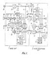
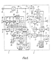
- the radio telephone apparatus comprises a base unit 1 coupled to a radio telephone set 2 through one of a plurality of radio channels including a control channel (C-CH) and a plurality of speech channels (S-CHs), and also connected to a wired telephone line 3.
- Base unit 1 includes an AC/DC converter 25 and AC plug 24, in order to produce a DC voltage (Vcc) from a commercial AC power source.
- the DC voltage is supplied to electrical components of base unit 1.
- Radio telephone set 2 includes a small rechargeable storage battery 29 which supplies a DC voltage to electrical components of the radio telephone set 2.
- the terminals of battery 29 are connected to charging terminals 28.
- the terminals 28 are connected to supply terminals 27 of base unit 1, one of which is connected to the AC/DC converter 25 through a resistor 26 and the other of which is connected to ground.
- the converted DC voltage is supplied to battery 29 through resistor 26 and terminals 27 and 28.
- Resistor 26 is a current limiting resistor to limit the current supplied to terminals 27.
- a signal sent from wired telephone line 3 is applied to hybrid circuit 4 via line relay 33 when that relay is closed (ON state).
- Hybrid circuit 4 sends the applied signal to switches 34 and 35. These switches are always in opposite states, so the signal from hybrid circuit 4 is supplied either to transmitter 5 (when switch 34 is closed) or to a loudspeaker 38 via an amplifier 37 (when switch 35 is closed).
- Transmitter 5 modulates a carrier wave with the signal fed to it and transmits the modulated signal to radio telephone set 2 via a transmitting antenna 6.
- the carrier wave is supplied from a synthesizer 9 and has a frequency corresponding to a radio channel selected, in a known manner, by synthesizer 9.
- the signal transmitted from radio telephone set 2 is received by receiving antenna 7 and demodulated by receiver 8 using the carrier wave supplied by synthesizer 9.
- the demodulated signal is sent to hybrid circuit 4 when switch 36 is closed and then sent to wired telephone line 3 when line relay 33 is closed.
- the demodulated signal is also supplied to received field detector 10 and identification signal detector 11.
- Detector 10 is a carrier squelch circuit or a noise squelch circuit, and detects the intensity of the received field, while detector 11 determines whether the identification signal contained in the demodulated signal corresponds to a specific identification signal allotted to radio telephone set 2.
- the detected signals from detectors 10 and 11 are supplied to control circuit 12.
- the demdulated signal from receiver 8 is also supplied to control circuit 12 to decode a control signal contained in the demodulated signal to establish a speech path.
- the call signal detector 30 detects a call signal (16 Hz signal) sent from wired telephone line 3, and informs control circuit 12 when the call signal has been received.
- Control circuit 12 includes a microcomputer, a RAM for storing operation data and ROM containing a stored operation program. Control circuit 12 controls transmitter 5, synthesizer 9, line relay 33, switches 34, 35 and 36 (to establish a speech path is response to the output signals of receiver 8), and detectors 10, 11 and 30. Comntrol circuit 12 is also connected to the junction between resistor 26 and the upper of terminals 27, and detects the voltage a at this point. This voltage a drops when radio telephone set 2 is installed in base unit 1 because a charging current is supplied to battery 29 through terminals 27 and 28. Control circuit 12 determines whether or not radio telephone set 2 is installed in base unit 1 depending on whether the voltage a is above or below a predetermined value.
- Radio telephone set 2 a signal transmitted from base unit 1 is received by receiving antenna 13, demodulated by receiver 14 and then applied to speaker 15.
- the signal demodulated by receiver 14 is supplied to received signal detector 20, identification signal detector 21 and control circuit 22.
- a voice signal applied to microphone 16 is passed to transmitter 17 as a modulation input and then transmitted to base unit 1 through transmitting antenna 18.
- Control circuit 22 includes a microcomputer, a RAM for storing operation data and ROM containing a stored operation program. Control circuit 22 controls receiver 14, transmitter 17 and synthesizer 19 (to establish a speech path in response to the output signals of receiver 14), and detectors 20 and 21.
- Control circuit 22 also causes speaker 23 to produce a ringing sound when it detects a ringing signal in the demodulated signal from receiver 14. Speakers 15 and 23 and microphone 16 are of designs which consume very little power. Control circuit 22 controls the call origination operation in response to key data from calling origination key 31 and dialing keys 32. Keys 31 and 32 are arranged on the top surface of radio telephone set 2, as shown in Figure 2, so that they can be operated when radio telephone set 2 is installed in base unit 1. Key 31 is a slide type key and keys 32 are push-type keys.
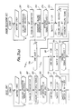
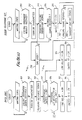
- FIG. 3 shows the operation of this apparatus.
- control circuit 12 causes transmitter 5 to turn off and control circuit 22 causes transmitter 17 to turn off, in order to prevent unnecessary transmission of radio signals.
- Receiver 14 is also normally off, but control circuit 22 periodically turns it on briefly; this minimizes the power consumption of the receiver when it is in the waiting state.
- switches 34 and 36 are in the ON state (closed) and switch 35 is in the OFF state (opened).
- control circuit 22 When call origination key 31 is slid to be in the ON state, the key data is supplied to control circuit 22, which recognizes this as a request to originate a call, step 201, and turns transmitter 17 on, step 202. Control circuit 22 then sends a call origination signal to transmitter 17, which modulates and transmits this signal, step 203. In this state, synthesizer 19 supplies transmitter 17 with a carrier wave corresponding to a control channel. After transmitting the call origination signal, control circuit 22 causes receiver 14 to turn on and remain in the ON state.
- control circuit 12 When control circuit 12 recognizes the demodulated signal as a call origination signal, step 101, it turns transmitter 5 on, step 102, and then sequentially switches the receiving channel through the speech channels to find a vacant speech channel. If control circuit 12 finds a vacant speech channel, it sends a response signal to transmitter 5 to modulate and transmit a response signal through the control channel, step 103, including a speech channel signal indicating the vacant speech channel and a predetermined identification signal. Control circuit 12 then monitors the level of voltage a, step 104, to determine whether radio telephone set 2 is installed in base unit 1. If not, control circuit 12, selects the normal mode of operation and sends control signals to line relay 33 to connect wired telephone line 3 to hybrid circuit 4, step 105, and to synthesizer 9 to switch the control channel to the selected speech channel, step 106.
- control circuit 22 When receiver 14 receives the transmitted response signal, it demodulates the signal and sends the demodulated signal to control circuit 22.
- control circuit 22 recognizes this as the response signal, step 204, it sends a control signal to synthesizer 9 to switch the control channel to the speech channel in accordance with the speech channel portion of the response signal, step 205.
- control circuit 22 compares the identification signal in the response signal with the identification data stored therein. If the identification signal does not correspond to the predetermined identification data, the demodulated signal is not responded to. If the response signal is not received for a prede termined period, step 206, control circuit 22 annuls the received request for call origination and causes the transmitter 17 to turn off, step 212. Control circuit 22 also causes receiver 14 to turn off and on periodically. Therefore, radio telephone set 2 is placed in the waiting state again.
- a dial tone from wired telephone line 3 is transmitted to radio telephone set 2 and is emitted by speaker 15.
- the dialling keys 32 are depressed to transmit a dialling signal to base unit 1 after the dial tone is heard through speaker 15.
- Control circuit 22 receives the dialling key data from dialling keys 32 and passes the data to transmitter 17, steps 207 and 208.
- Transmitter 17 modulates and transmits the dialling signal through the speech channel.
- dialling signal When the dialling signal is received by receiver 8, it is demodulated and passed to control circuit 12, which then sends a dialling signal, such as a DTMF (dual tone multi-frequency) signal or a DP (dial pulse) signal, to wired telephone line 3, in response to the received dialling signal, steps 107 and 108.
- a dialling signal such as a DTMF (dual tone multi-frequency) signal or a DP (dial pulse) signal
- control circuit 22 When, at the end of the call, the call origination key 31 is slid back to its initial position, control circuit 22 detects that as the end of speech and sends an end signal to transmitter 17 to be transmitted to base unit 1, steps 209 and 210. Control circuit 22 then sends a control signal to synthesizer 19 to switch the speech channel to the control channel, step 211, and turns transmitter 17 off, step 212. Control circuit 12 also causes receiver 14 to turn on and off periodically. Thus radio telephone set 2 is in the waiting state again.
- control circuit 12 When the end signal is received by receiver 8, it is demodulated and sent to control circuit 12, which sends a control signal to synthesizer 9 to switch the speech channel to the control channel, steps 109 and 110. Control circuit 12 then sends control signals to line relay 33 and transmitter 5 to disconnect wired telephone line 3 from hybrid circuit 4 and turn off transmitter 5, steps 111 and 112. Thus base unit 1 is also in the waiting state again.
- control circuit 12 finds that the radio telephone set 2 is installed in the base unit 1 at step 104, it selects the loudspeaker mode and sends a control signal to line relay 33 to connect wired telephone line 3 to hybrid circuit 4, step 113. Control circuit 12 also sends a control signal to synthesizer 9 to switch the control channel to the vacant speech channel, step 114. Control circuit 12 then sends control signals b, c and d to switches 34, 35 and 36 to connect hybrid circuit 4 to amplifier 37 and disconnect hybrid circuit 4 from transmitter 5 and receiver 8, step 115. This places the radio telephone apparatus in the receiving loudspeaker mode, using loudspeaker 38.
- control circuit 12 passes the dialling signal received from the radio telephone set 2 to wired telephone line 3, steps 116 and 117.
- a ringing signal from wired telephone line 3 is emitted by loudspeaker 38 if the called telephone set is not busy. If the called party responds to this call, the responding voice signal from the called telephone set is emitted by loudspeaker 38. If the called telephone set is busy, a busy tone from wired telephone line 3 is emitted by loudspeaker 38.
- This receiving loudspeaker mode, using loudspeaker 38, is continued as long as radio telephone set 2 is installed in base unit 1, step 118. In this state, when the end signal is received from radio telephone set 2, step 120, control circuit 12 carries out the end of speech operation as described above, steps 110, 111 and 112.
- control circuit 12 If the user picks up radio telephone set 2 after hearing the ringing signal or the response voice signal from loudspeaker 38, control circuit 12 detects that the radio telephone set 2 is no longer installed in base unit 1 from the level of voltage a , step 118. Control circuit 12 then sends control signals b, c, and d to switches 34, 35 and 36, in order to connect hybrid circuit 4 to transmitter 5 and receiver 8 and disconnect it from amplifier 37. Therefore, the radio telephone apparatus is placed in the normal mode, and uses speaker 15 and microphone 16, instead of the receiving loudspeaker mode.
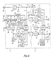
- Figure 4 shows a modified circuit, in which the amplifier 37 is replaced by a variable gain amplifier 37 ⁇ the gain of which is selectable at two levels; a signal level detector 39 is also provided, and switch 36 is omitted.
- Signal level detector 39 is fed with the output signal from receiver 8 and determines whether it is above a predetermined level. If it is, detector 39 sends a signal to control circuit 12, which sends a control signal e to amplifier 37 ⁇ to reduce its gain. Since the gain of amplifier 37 ⁇ is reduced when the magnitude of the output signal from receiver 8 is increased, the magnitude of the signal emitted by loudspeaker 38 is reduced, and is therefore too low to have any significant effect if it enters microphone 16.
- the apparatus is able to carry out loudspeaker communication using loudspeaker 38 and microphone 16, instead of only loudspeaker 38.
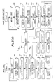
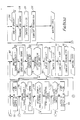
- FIG. 5 shows the operation of this modified circuit.
- control circuit 12 After transmitting the response signal to radio telephone set 2 in response to the calling origination signal, step 103, control circuit 12 determines whether radio telephone set 2 is installed in base unit 1, step 104. If it is, control circuit 12 selects the loudspeaker communication mode and causes line relay 33 to connect hybrid circuit 4 to wired telephone line 3, step 113. Control circuit 12 then sends the control signal to synthesizer 9 to switch the control channel to the speech channel, step 114, and control signals b and c to switches 34 and 35 to connect hybrid circuit 4 to amplifier 37 ⁇ and disconnect it from transmitter 5, step 125. Therefore, the radio telephone apparatus is in the loudspeaker communication mode, using loudspeaker 38 and microphone 16.
- control circuit 12 monitors the output of detector 39. If control circuit 12 finds that there is an output from detector 39, step 126, it sends the control signal e to amplifier 37 ⁇ to reduce the gain, step 127. If the output from detector 39 ends, step 126, control circuit 12 stops sending the control signal e to amplifier 37 ⁇ to return it to the initial high gain.
- control circuit 12 carries out the end operation as described before, steps 110, 111 and 112.
- control circuit 12 sends control signals b and c to switches 34 and 35, in order to connect hybrid circuit 4 to transmitter 5 and disconnect it from amplifier 37 ⁇ , step 128.
- the radio telephone apparatus is returned to the normal mode with speaker 215 and microphone 16 from the loudspeaker communication mode.
- Figure 6 shows an additional modification of the circuit, in which a loudspeaker switch 40 is arranged on the top surface of base unit 1 as shown in Figure 7.
- FIGS. 8 and 9 show the operation of this further modified circuit.
- control circuit 12 After transmitting the response signal to radio telephone set 2 in response to the calling origination signal, step 103, control circuit 12 determines whether loudspeaker switch 40 is depressed, step 132. If so, control circuit 12 further determines whether radio telephone set 2 is installed in base unit 1, step 104. If not, control circuit 12 sends control signals b, c, and d to switches 34, 35, and 36, in order to connect hybrid circuit 4 to receiver 8 and amplifier 37 ⁇ and disconnect it from transmitter 5, step 133. Therefore, loudspeaker communication is carried out with loudspeaker 38 and microphone 16 after the speech path between the called telephone set and base unit 1 is established.
- control circuit 12 sends control signals b, c, and d to switches 34, 35, and 36, in order to disconnect hybrid circuit 4 from amplifier 37 ⁇ and connect it to transmitter 5 and receiver 8, step 135. Therefore, the radio telephone apparatus is placed in the normal mode with speaker 15 and microphone 16.
- control circuit 12 finds that radio telephone set 2 is installed in base unit 1 in step 104, it causes line relay 33 to connect wired telephone line 3 to hybrid circuit 4 and synthesizer 9 to switch the control channel to the speech channel, steps 140 and 141.
- Control circuit 12 sends control signals b, c, and d to switches 34, 35, and 36, in order to connect hybrid circuit 4 to amplifier 37 ⁇ and disconnect it from transmitter 5 and receiver 8, step 142.
- the receiving loudspeaker operation is carried out. In this state, control circuit 12 always causes amplifier 37 ⁇ to select the higher gain by control signal e.
- control circuit 12 finds that radio telephone set 2 is not installed in base unit 1 in the receiving loudspeaker operation, step 146, control circuit 12 sends control signals b, c, and d to switches 34, 35, and 36, in order to disconnect hybrid circuit 4 from transmitter 5 and connect it to receiver 8 and amplifier 38, step 133.
- the radio telephone apparatus is thus placed in the loudspeaker communication mode with loudspeaker 38 and microphone 16.
- control circuit 12 also receives the end signal from radio telephone set 2 in the receiving loudspeaker operation step 147, it sends control signals b, c, and d to the switches 34, 35, and 36, in order to disconnect hybrid circuit 4 from amplifier 37 ⁇ and connect it to transmitter 5 and receiver 8, step 148. Thereafter, control circuit 12 carries out the end operation as described above, steps 110, 111, and 112.
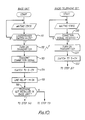
- Figure 10 shows a modified mode of operation of this further modified circuit, in which the apparatus is able to operate the calling origination in response to the depression of loudspeaker switch 40, instead of the operation of the calling origination key 31.
- control circuit 12 finds that loudspeaker switch 40 is in the ON state by being depressed while the system is in the waiting state, step 151, it sends a connection signal to transmitter 5 after turning it on, steps 152 and 153.
- Transmitter 5 transmits the connection signal to radio telephone set 2 through the control channel.
- the connection signal includes the speech channel signal indicating the selected vacant speech channel and the predetermined identification signal.
- Control circuit 12 then sends control signals to synthesizer 9 and line relay 33 to select the chosen speech channel and connect hybrid circuit 4 to wired telephone line 3, steps 154 and 155. Thereafter, control circuit 12 determines whether radio telephone set 2 is installed in base unit 1, step 156. If so, the radio telephone apparatus is placed in the receiving loudspeaker mode, and if not, it is placed in the loudspeaker communication mode, as described above.
- control circuit 22 detects that the connection signal is received, step 220, it sends the control signal to synthesizer 19 to select the indicated speech channel after transmitter 17 is turned on, steps 221 and 222.
- the speech path between base unit 1 and radio telephone set 2 is established.
- the end operation is carried out by the operation of key 31.
- base unit 1 may carry out the end operation in response to detecting that the called telephone set is disconnected from wired telephone line.
- signal level detector 39 determines whether 1 ⁇ 2he output signal level from receiver 8 is beyond a single predetermined level and amplifier 37 ⁇ selects one of two gains by the control signal e from control circuit 12. However, detector 39 may compare the output signal level with a plurality of predetermined levels and amplifier 37 ⁇ may select one of a plurality of gains according to the signal level determined by detector 39.
- control circuit 12 determines whether radio telephone set 2 is installed in base unit 1 by monitoring the voltage a corresponding to the charging current. However, control circuit 12 may determine whether the radio telephone set 2 is installed by means of a switch on base unit 1 which is operated when the radio telephone set 2 is installed in base unit 1. Furthermore, transmitters 5 and 17 may reduce the transmitting power when radio telephone set 2 is installed in base unit 1 to reduce power consumption. Also, control circuit 22 may send a dialling signal to control circuit 12 through the charging line including terminals 27 and 28 when radio telephone set 2 is installed in base unit 1.
Abstract
Description
- This invention relates to the field of radio telephones, typically cordless telephones and, more particularly, to means for increasing the sound volume in certain circumstances.
- Radio telephones are comprised of a radio telephone set and a base unit. The radio telephone set has a handset, and the base unit is connected to wired telephone lines for exchanging speech signals between the wired telephone lines and the radio telephone set through a radio channel. The base unit and the radio telephone set each have a transmitter and a receiver.
- When a call signal appears at a wired telephone line, the base unit transmits a paging signal to the radio telephone set through a predetermined control channel to set up a speech channel. The paging signal includes a channel signal to indicate one of a number of speech channels. In response, the radio telephone set sends out a paging response signal through the control channel. The base unit detects the intensity of the received paging response signal sent from the radio telephone set, i.e. the intensity of the paging response signal on the control channel. Then, the base unit stops the transmission of the paging signal when the detected intensity exceeds a predetermined level, and switches the radio channel between the base unit and the radio telephone set from the control channel to the speech channel indicated in the paging signal. The radio telephone set also switches the radio channel from the paging channel to the speech channel set by the received paging signal. Thereafter, the base unit transmits a bell ringing signal to the radio telephone set via the speech channel. After transmitting the ringing signal, the base unit establishes a speech path between the wired telephone line and the radio telephone set when it receives an "off-hook" signal from the radio telephone set.
- When the base unit receives a call origination signal (an "off-hook" signal) from the radio telephone set through the control channel while it is in a waiting state, it detects the request from the radio telephone set to originate a call and transmits a response signal which includes a channel signal indicating one of a plurality of speech channels. The base unit then establishes a speech path between the wired telephone line and itself, and switches the radio channel from the control channel to the speech channel in response to the response signal. After receiving the response signal, the radio telephone set also switches the radio channel from the control channel to the speech channel in response to the received response signal.
- If, in this state, the radio telephone set transmits dialing signals to the base unit through the speech channel by a dialing operation, the dialing signal is transmitted to the wired telephone line via the base unit.
- Thus, the radio telephone apparatus carries out the operations of receiving incoming telephone calls from the wired telephone line and originating calls from the radio telephone set.
- However, known radio telephones have a serious drawback. Sufficiently large loudspeakers cannot be used in the apparatus, because it is necessary for the radio telephone set to be compact and light. If a loudspeaker with a large enough speaker were used, it would be extremely difficult to drive the loudspeaker to generate speech signals, because the capacity of the power source of the radio telephone set is insufficient. Generally, the power source is a small storage battery used to drive the components of the radio telephone set. These components typically have low power requirements. Loudspeakers typically have high power requirements.
- The main object of the present invention is therefore to provide a a radio telephone apparatus which is capable of producing speech signals from a loudspeaker.
- Accordingly the present invention provides radio telephone apparatus comprising a base unit coupled to a wired telephone line, and a radio telephone set including a battery and coupled to the base unit through a radio channel characterized in that the base unit includes a loudspeaker) and mode selection means for selecting a loudspeaker mode, in which the loudspeaker is connected to the wired telephone line.
- A radio telephone system embodying the invention, and various modifications thereof, will now be described, by way of example, with reference to the drawings, in which:
- Figure 1 is a block diagram of a radio telephone system embodying the present invention;
- Figure 2 is an external view of the radio telephone apparatus of Figure 1;
- Figure 3 is a flow chart of the operation of the radio telephone apparatus of Figure 1;
- Figure 4 is a block diagram of a modification of the Figure 1 apparatus;
- Figure 5 is a flow chart of the operation of the Figure 4 apparatus;
- Figure 6 is a block diagram of a further modification of the apparatus of Figure 1;
- Figure 7 is an external view of the radio telephone apparatus of Figure 6; and
- Figures 8 to 10 are flow charts of the operation of the radio telephone apparatus of Figure 6.
- The radio telephone apparatus has a base unit and a radio telephone set, the base unit being coupled to a wired telephone line and connected to the radio telephone set through a radio channel. The base unit operates by DC power converted from an AC source, while the radio telephone set is powered by a small storage battery, which may be charged by the DC power when the set is installed in or on the base unit. The radio telephone set also includes call origination keys, dialing keys, and a microphone and speaker. The base unit includes a loudspeaker for generating sound signals from said wired telephone line and a control circuit. The control circuit selects a loudspeaker mode in response to the call origination signal by the operation of the call origination key if the radio telephone set is installed in the base unit. The control circuit connects the loudspeaker to the wired telephone line if the loudspeaker mode is selected, so that the sound signals may be heard through the loudspeaker.
- In a brief and simplified form, the various circuits described operate as follows.
- a) The circuit of Figure 1 has two modes, the normal mode and the loudspeaker-only mode; the wired telephone line is connected (via a hybrid circuit, in all cases) to the transmitter and receiver of the base unit in the normal mode, and to the loudspeaker (alone) in the loudspeaker-only mode.
- b) In the modified circuit of Figure 4, the loudspeaker mode is a loudspeaker-and-microphone mode, in which the wired telephone line is also connected to the receiver in the base unit, and the connection from the wired telephone line to the loudspeaker is via a variable gain amplifier the gain of which is reduced if the microphone signal (as measured at the output of the receiver in the base unit) exceeds a predetermined level.
- c) In the further modified circuit of Fig. 6, there are two submodes to the loudspeaker mode, the loudspeaker-only mode or the loudspeaker-and-microphone mode, selected by a control switch on the base unit.
- Referring to Figure 1, the radio telephone apparatus comprises a
base unit 1 coupled to a radio telephone set 2 through one of a plurality of radio channels including a control channel (C-CH) and a plurality of speech channels (S-CHs), and also connected to awired telephone line 3.Base unit 1 includes an AC/DC converter 25 andAC plug 24, in order to produce a DC voltage (Vcc) from a commercial AC power source. The DC voltage is supplied to electrical components ofbase unit 1.Radio telephone set 2 includes a smallrechargeable storage battery 29 which supplies a DC voltage to electrical components of theradio telephone set 2. The terminals ofbattery 29 are connected tocharging terminals 28. Whenradio telephone set 2 is installed inbase unit 1, as shown in Figure 2, theterminals 28 are connected tosupply terminals 27 ofbase unit 1, one of which is connected to the AC/DC converter 25 through aresistor 26 and the other of which is connected to ground. Thus the converted DC voltage is supplied tobattery 29 throughresistor 26 andterminals Resistor 26 is a current limiting resistor to limit the current supplied toterminals 27. - A signal sent from
wired telephone line 3 is applied tohybrid circuit 4 vialine relay 33 when that relay is closed (ON state).Hybrid circuit 4 sends the applied signal to switches 34 and 35. These switches are always in opposite states, so the signal fromhybrid circuit 4 is supplied either to transmitter 5 (whenswitch 34 is closed) or to aloudspeaker 38 via an amplifier 37 (whenswitch 35 is closed).Transmitter 5 modulates a carrier wave with the signal fed to it and transmits the modulated signal toradio telephone set 2 via a transmitting antenna 6. The carrier wave is supplied from a synthesizer 9 and has a frequency corresponding to a radio channel selected, in a known manner, by synthesizer 9. - The signal transmitted from
radio telephone set 2 is received by receiving antenna 7 and demodulated by receiver 8 using the carrier wave supplied by synthesizer 9. The demodulated signal is sent tohybrid circuit 4 whenswitch 36 is closed and then sent to wiredtelephone line 3 whenline relay 33 is closed. The demodulated signal is also supplied to receivedfield detector 10 andidentification signal detector 11.Detector 10 is a carrier squelch circuit or a noise squelch circuit, and detects the intensity of the received field, whiledetector 11 determines whether the identification signal contained in the demodulated signal corresponds to a specific identification signal allotted toradio telephone set 2. The detected signals fromdetectors circuit 12. The demdulated signal from receiver 8 is also supplied to controlcircuit 12 to decode a control signal contained in the demodulated signal to establish a speech path. - The
call signal detector 30 detects a call signal (16 Hz signal) sent fromwired telephone line 3, and informscontrol circuit 12 when the call signal has been received. -
Control circuit 12 includes a microcomputer, a RAM for storing operation data and ROM containing a stored operation program.Control circuit 12controls transmitter 5, synthesizer 9,line relay 33, switches 34, 35 and 36 (to establish a speech path is response to the output signals of receiver 8), anddetectors Comntrol circuit 12 is also connected to the junction betweenresistor 26 and the upper ofterminals 27, and detects the voltage a at this point. This voltage a drops when radio telephone set 2 is installed inbase unit 1 because a charging current is supplied tobattery 29 throughterminals Control circuit 12 determines whether or not radio telephone set 2 is installed inbase unit 1 depending on whether the voltage a is above or below a predetermined value. - In
radio telephone set 2, a signal transmitted frombase unit 1 is received by receivingantenna 13, demodulated byreceiver 14 and then applied tospeaker 15. In the same manner as inbase unit 1, the signal demodulated byreceiver 14 is supplied to receivedsignal detector 20,identification signal detector 21 andcontrol circuit 22. A voice signal applied tomicrophone 16 is passed totransmitter 17 as a modulation input and then transmitted tobase unit 1 through transmittingantenna 18.Control circuit 22 includes a microcomputer, a RAM for storing operation data and ROM containing a stored operation program.Control circuit 22controls receiver 14,transmitter 17 and synthesizer 19 (to establish a speech path in response to the output signals of receiver 14), anddetectors Control circuit 22 also causesspeaker 23 to produce a ringing sound when it detects a ringing signal in the demodulated signal fromreceiver 14.Speakers microphone 16 are of designs which consume very little power.Control circuit 22 controls the call origination operation in response to key data from callingorigination key 31 and dialingkeys 32.Keys radio telephone set 2, as shown in Figure 2, so that they can be operated when radio telephone set 2 is installed inbase unit 1.Key 31 is a slide type key andkeys 32 are push-type keys. - Figure 3 shows the operation of this apparatus.
- In a waiting state,
control circuit 12causes transmitter 5 to turn off andcontrol circuit 22causes transmitter 17 to turn off, in order to prevent unnecessary transmission of radio signals.Receiver 14 is also normally off, butcontrol circuit 22 periodically turns it on briefly; this minimizes the power consumption of the receiver when it is in the waiting state. Also, in the waiting state, switches 34 and 36 are in the ON state (closed) andswitch 35 is in the OFF state (opened). - When
call origination key 31 is slid to be in the ON state, the key data is supplied to controlcircuit 22, which recognizes this as a request to originate a call,step 201, and turnstransmitter 17 on,step 202.Control circuit 22 then sends a call origination signal totransmitter 17, which modulates and transmits this signal,step 203. In this state,synthesizer 19supplies transmitter 17 with a carrier wave corresponding to a control channel. After transmitting the call origination signal,control circuit 22 causesreceiver 14 to turn on and remain in the ON state. - The transmitted call origination signal is received and demodulated by receiver 8, which feeds the demodulated signal to control
circuit 12. Whencontrol circuit 12 recognizes the demodulated signal as a call origination signal,step 101, it turnstransmitter 5 on,step 102, and then sequentially switches the receiving channel through the speech channels to find a vacant speech channel. Ifcontrol circuit 12 finds a vacant speech channel, it sends a response signal totransmitter 5 to modulate and transmit a response signal through the control channel,step 103, including a speech channel signal indicating the vacant speech channel and a predetermined identification signal.Control circuit 12 then monitors the level of voltage a,step 104, to determine whether radio telephone set 2 is installed inbase unit 1. If not, controlcircuit 12, selects the normal mode of operation and sends control signals toline relay 33 to connectwired telephone line 3 tohybrid circuit 4,step 105, and to synthesizer 9 to switch the control channel to the selected speech channel,step 106. - When
receiver 14 receives the transmitted response signal, it demodulates the signal and sends the demodulated signal to controlcircuit 22. Whencontrol circuit 22 recognizes this as the response signal,step 204, it sends a control signal to synthesizer 9 to switch the control channel to the speech channel in accordance with the speech channel portion of the response signal,step 205. For this,control circuit 22 compares the identification signal in the response signal with the identification data stored therein. If the identification signal does not correspond to the predetermined identification data, the demodulated signal is not responded to. If the response signal is not received for a prede termined period,step 206,control circuit 22 annuls the received request for call origination and causes thetransmitter 17 to turn off,step 212.Control circuit 22 also causesreceiver 14 to turn off and on periodically. Therefore, radio telephone set 2 is placed in the waiting state again. - When the speech channel between
base unit 1 and radio telephone set 2 is established, a dial tone fromwired telephone line 3 is transmitted toradio telephone set 2 and is emitted byspeaker 15. The diallingkeys 32 are depressed to transmit a dialling signal tobase unit 1 after the dial tone is heard throughspeaker 15.Control circuit 22 receives the dialling key data from diallingkeys 32 and passes the data totransmitter 17,steps Transmitter 17 modulates and transmits the dialling signal through the speech channel. When the dialling signal is received by receiver 8, it is demodulated and passed to controlcircuit 12, which then sends a dialling signal, such as a DTMF (dual tone multi-frequency) signal or a DP (dial pulse) signal, towired telephone line 3, in response to the received dialling signal, steps 107 and 108. Thus, the call origination operation is carried out and the radio telephone apparatus is placed in a communication state. - When, at the end of the call, the
call origination key 31 is slid back to its initial position,control circuit 22 detects that as the end of speech and sends an end signal totransmitter 17 to be transmitted tobase unit 1,steps Control circuit 22 then sends a control signal tosynthesizer 19 to switch the speech channel to the control channel,step 211, and turnstransmitter 17 off,step 212.Control circuit 12 also causesreceiver 14 to turn on and off periodically. Thus radio telephone set 2 is in the waiting state again. - When the end signal is received by receiver 8, it is demodulated and sent to control
circuit 12, which sends a control signal to synthesizer 9 to switch the speech channel to the control channel, steps 109 and 110.Control circuit 12 then sends control signals toline relay 33 andtransmitter 5 to disconnectwired telephone line 3 fromhybrid circuit 4 and turn offtransmitter 5,steps base unit 1 is also in the waiting state again. - If
control circuit 12 finds that the radio telephone set 2 is installed in thebase unit 1 atstep 104, it selects the loudspeaker mode and sends a control signal toline relay 33 to connectwired telephone line 3 tohybrid circuit 4,step 113.Control circuit 12 also sends a control signal to synthesizer 9 to switch the control channel to the vacant speech channel,step 114.Control circuit 12 then sends control signals b, c and d to switches 34, 35 and 36 to connecthybrid circuit 4 toamplifier 37 and disconnecthybrid circuit 4 fromtransmitter 5 and receiver 8,step 115. This places the radio telephone apparatus in the receiving loudspeaker mode, usingloudspeaker 38. In this mode, since the dial tone fromwired telephone line 3 is supplied toloudspeaker 38 throughline relay 33,hybrid circuit 4, switch 35 andamplifier 37, the dial tone is emitted byloudspeaker 38. Thereafter,control circuit 12 passes the dialling signal received from the radio telephone set 2 towired telephone line 3,steps - After the call origination operation has been carried out, a ringing signal from
wired telephone line 3 is emitted byloudspeaker 38 if the called telephone set is not busy. If the called party responds to this call, the responding voice signal from the called telephone set is emitted byloudspeaker 38. If the called telephone set is busy, a busy tone fromwired telephone line 3 is emitted byloudspeaker 38. This receiving loudspeaker mode, usingloudspeaker 38, is continued as long as radio telephone set 2 is installed inbase unit 1,step 118. In this state, when the end signal is received fromradio telephone set 2,step 120,control circuit 12 carries out the end of speech operation as described above, steps 110, 111 and 112. - If the user picks up radio telephone set 2 after hearing the ringing signal or the response voice signal from
loudspeaker 38,control circuit 12 detects that the radio telephone set 2 is no longer installed inbase unit 1 from the level of voltage a,step 118.Control circuit 12 then sends control signals b, c, and d to switches 34, 35 and 36, in order to connecthybrid circuit 4 totransmitter 5 and receiver 8 and disconnect it fromamplifier 37. Therefore, the radio telephone apparatus is placed in the normal mode, and usesspeaker 15 andmicrophone 16, instead of the receiving loudspeaker mode. - Figure 4 shows a modified circuit, in which the
amplifier 37 is replaced by a variable gain amplifier 37ʹ the gain of which is selectable at two levels; asignal level detector 39 is also provided, and switch 36 is omitted.Signal level detector 39 is fed with the output signal from receiver 8 and determines whether it is above a predetermined level. If it is,detector 39 sends a signal to controlcircuit 12, which sends a control signal e to amplifier 37ʹ to reduce its gain. Since the gain of amplifier 37ʹ is reduced when the magnitude of the output signal from receiver 8 is increased, the magnitude of the signal emitted byloudspeaker 38 is reduced, and is therefore too low to have any significant effect if it entersmicrophone 16. With this modified circuit, the apparatus is able to carry out loudspeakercommunication using loudspeaker 38 andmicrophone 16, instead ofonly loudspeaker 38. - Figure 5 shows the operation of this modified circuit. After transmitting the response signal to radio telephone set 2 in response to the calling origination signal,
step 103,control circuit 12 determines whether radio telephone set 2 is installed inbase unit 1,step 104. If it is,control circuit 12 selects the loudspeaker communication mode and causesline relay 33 to connecthybrid circuit 4 towired telephone line 3,step 113.Control circuit 12 then sends the control signal to synthesizer 9 to switch the control channel to the speech channel,step 114, and control signals b and c toswitches hybrid circuit 4 to amplifier 37ʹ and disconnect it fromtransmitter 5,step 125. Therefore, the radio telephone apparatus is in the loudspeaker communication mode, usingloudspeaker 38 andmicrophone 16. In this mode, the dial tone fromwired telephone line 3 is emitted byloudspeaker 38 untilcontrol circuit 12 sends the dialing signal towired telephone line 3. After the speech path between the called telephone set andbase unit 1 is established by the dialling signal, steps 116 and 117,control circuit 12 monitors the output ofdetector 39. Ifcontrol circuit 12 finds that there is an output fromdetector 39,step 126, it sends the control signal e to amplifier 37ʹ to reduce the gain,step 127. If the output fromdetector 39 ends,step 126,control circuit 12 stops sending the control signal e to amplifier 37ʹ to return it to the initial high gain. - This loudspeaker communication mode is continued as long as radio telephone set 2 is installed in
base unit 1,step 118. In this state, when the end signal is received fromradio telephone set 2,step 120,control circuit 12 carries out the end operation as described before, steps 110, 111 and 112. - If the user picks up radio telephone set 2 in this loudspeaker communication mode,
control circuit 12 sends control signals b and c toswitches hybrid circuit 4 totransmitter 5 and disconnect it from amplifier 37ʹ,step 128. Thus the radio telephone apparatus is returned to the normal mode with speaker 215 andmicrophone 16 from the loudspeaker communication mode. - Figure 6 shows an additional modification of the circuit, in which a
loudspeaker switch 40 is arranged on the top surface ofbase unit 1 as shown in Figure 7. - Figures 8 and 9 show the operation of this further modified circuit. After transmitting the response signal to radio telephone set 2 in response to the calling origination signal,
step 103,control circuit 12 determines whether loudspeaker switch 40 is depressed,step 132. If so,control circuit 12 further determines whether radio telephone set 2 is installed inbase unit 1,step 104. If not, controlcircuit 12 sends control signals b, c, and d to switches 34, 35, and 36, in order to connecthybrid circuit 4 to receiver 8 and amplifier 37ʹ and disconnect it fromtransmitter 5,step 133. Therefore, loudspeaker communication is carried out withloudspeaker 38 andmicrophone 16 after the speech path between the called telephone set andbase unit 1 is established. Thereafter, whenloudspeaker switch 40 is depressed and is in the OFF state,step 134,control circuit 12 sends control signals b, c, and d to switches 34, 35, and 36, in order to disconnecthybrid circuit 4 from amplifier 37ʹ and connect it totransmitter 5 and receiver 8,step 135. Therefore, the radio telephone apparatus is placed in the normal mode withspeaker 15 andmicrophone 16. - If
control circuit 12 finds that radio telephone set 2 is installed inbase unit 1 instep 104, it causesline relay 33 to connectwired telephone line 3 tohybrid circuit 4 and synthesizer 9 to switch the control channel to the speech channel, steps 140 and 141.Control circuit 12 sends control signals b, c, and d to switches 34, 35, and 36, in order to connecthybrid circuit 4 to amplifier 37ʹ and disconnect it fromtransmitter 5 and receiver 8,step 142. Thus, the receiving loudspeaker operation is carried out. In this state,control circuit 12 always causes amplifier 37ʹ to select the higher gain by control signal e. Whencontrol circuit 12 finds that radio telephone set 2 is not installed inbase unit 1 in the receiving loudspeaker operation,step 146,control circuit 12 sends control signals b, c, and d to switches 34, 35, and 36, in order to disconnecthybrid circuit 4 fromtransmitter 5 and connect it to receiver 8 andamplifier 38,step 133. The radio telephone apparatus is thus placed in the loudspeaker communication mode withloudspeaker 38 andmicrophone 16. Whencontrol circuit 12 also receives the end signal from radio telephone set 2 in the receivingloudspeaker operation step 147, it sends control signals b, c, and d to theswitches hybrid circuit 4 from amplifier 37ʹ and connect it totransmitter 5 and receiver 8, step 148. Thereafter,control circuit 12 carries out the end operation as described above, steps 110, 111, and 112. - In this further modified circuit, when
loudspeaker switch 40 is in the ON state and radio telephone set 2 is installed inbase unit 1, in the normal mode, steps 137 and 138, the radio telephone apparatus is placed in the receiving loudspeaker mode. Also, whenloudspeaker switch 40 is in the ON state and radio telephone set 2 is not installed inbase unit 1, in the normal mode, steps 137 and 138, the radio telephone apparatus is placed in the loudspeaker communication mode. Furthermore, when radio telephone set 2 is installed inbase unit 1, in the loudspeaker communication mode,step 136, the radio telephone apparatus is placed in the receiving loudspeaker mode. - Figure 10 shows a modified mode of operation of this further modified circuit, in which the apparatus is able to operate the calling origination in response to the depression of
loudspeaker switch 40, instead of the operation of the callingorigination key 31. - When
control circuit 12 finds thatloudspeaker switch 40 is in the ON state by being depressed while the system is in the waiting state,step 151, it sends a connection signal totransmitter 5 after turning it on,steps Transmitter 5 transmits the connection signal to radio telephone set 2 through the control channel. The connection signal includes the speech channel signal indicating the selected vacant speech channel and the predetermined identification signal. -
Control circuit 12 then sends control signals to synthesizer 9 andline relay 33 to select the chosen speech channel and connecthybrid circuit 4 towired telephone line 3,steps control circuit 12 determines whether radio telephone set 2 is installed inbase unit 1,step 156. If so, the radio telephone apparatus is placed in the receiving loudspeaker mode, and if not, it is placed in the loudspeaker communication mode, as described above. - On the other hand, when
control circuit 22 detects that the connection signal is received,step 220, it sends the control signal tosynthesizer 19 to select the indicated speech channel aftertransmitter 17 is turned on,steps base unit 1 and radio telephone set 2 is established. - In the circuits described, the end operation is carried out by the operation of
key 31. However,base unit 1 may carry out the end operation in response to detecting that the called telephone set is disconnected from wired telephone line. - Also, in the circuits described,
signal level detector 39 determines whether ½he output signal level from receiver 8 is beyond a single predetermined level and amplifier 37ʹ selects one of two gains by the control signal e fromcontrol circuit 12. However,detector 39 may compare the output signal level with a plurality of predetermined levels and amplifier 37ʹ may select one of a plurality of gains according to the signal level determined bydetector 39. - Further, in the circuits described,
control circuit 12 determines whether radio telephone set 2 is installed inbase unit 1 by monitoring the voltage a corresponding to the charging current. However,control circuit 12 may determine whether the radio telephone set 2 is installed by means of a switch onbase unit 1 which is operated when the radio telephone set 2 is installed inbase unit 1. Furthermore,transmitters base unit 1 to reduce power consumption. Also,control circuit 22 may send a dialling signal to controlcircuit 12 through the chargingline including terminals base unit 1.
Claims (10)
Applications Claiming Priority (2)
| Application Number | Priority Date | Filing Date | Title |
|---|---|---|---|
| JP62067813A JPS63234654A (en) | 1987-03-24 | 1987-03-24 | Radio telephone system |
| JP67813/87 | 1987-03-24 |
Publications (3)
| Publication Number | Publication Date |
|---|---|
| EP0284325A2 true EP0284325A2 (en) | 1988-09-28 |
| EP0284325A3 EP0284325A3 (en) | 1990-11-22 |
| EP0284325B1 EP0284325B1 (en) | 1993-11-03 |
Family
ID=13355760
Family Applications (1)
| Application Number | Title | Priority Date | Filing Date |
|---|---|---|---|
| EP88302447A Revoked EP0284325B1 (en) | 1987-03-24 | 1988-03-21 | Radio telephone |
Country Status (6)
| Country | Link |
|---|---|
| US (1) | US4969181A (en) |
| EP (1) | EP0284325B1 (en) |
| JP (1) | JPS63234654A (en) |
| KR (1) | KR920000140B1 (en) |
| CA (1) | CA1286810C (en) |
| DE (1) | DE3885325T2 (en) |
Families Citing this family (15)
| Publication number | Priority date | Publication date | Assignee | Title |
|---|---|---|---|---|
| JPH0368242A (en) * | 1989-08-07 | 1991-03-25 | Tamura Electric Works Ltd | Radio telephone equipment |
| JPH0370441U (en) * | 1989-11-08 | 1991-07-15 | ||
| JPH0451741A (en) * | 1990-06-20 | 1992-02-20 | Tamura Electric Works Ltd | Cordless telephone set |
| KR940003507B1 (en) * | 1990-08-30 | 1994-04-23 | 금성통신 주식회사 | Cordless telephone system |
| JPH04179356A (en) * | 1990-11-13 | 1992-06-26 | Mitsubishi Electric Corp | Codeless telephone set |
| JP2941963B2 (en) * | 1991-01-17 | 1999-08-30 | キヤノン株式会社 | Cordless telephone equipment |
| DE4130647A1 (en) * | 1991-09-14 | 1993-03-18 | Bosch Gmbh Robert | EMERGENCY CALL DEVICE |
| US5381460A (en) * | 1993-12-30 | 1995-01-10 | Uniden America Corp., | Monitor mode in a portable telephone |
| JPH08331234A (en) | 1995-03-24 | 1996-12-13 | Canon Inc | Telephony system |
| JPH0958U (en) * | 1996-06-04 | 1997-01-21 | シャープ株式会社 | Cordless telephone |
| DE19641755C2 (en) * | 1996-10-10 | 2002-06-13 | Deutsche Telekom Ag | Cordless telephone |
| US6115616A (en) * | 1998-05-28 | 2000-09-05 | International Business Machines Corporation | Hand held telephone set with separable keyboard |
| US6321080B1 (en) * | 1999-03-15 | 2001-11-20 | Lucent Technologies, Inc. | Conference telephone utilizing base and handset transducers |
| JP3599097B2 (en) * | 2000-10-10 | 2004-12-08 | 日本電気株式会社 | Method of calling portable communication device by peripheral device, portable communication device using the same, and peripheral device |
| TW563974U (en) * | 2002-02-06 | 2003-11-21 | Lite On Technology Corp | Electricity saving device for user for user interface terminal device of cellular phone |
Citations (5)
| Publication number | Priority date | Publication date | Assignee | Title |
|---|---|---|---|---|
| US3124657A (en) * | 1964-03-10 | peterson | ||
| EP0119602A1 (en) * | 1983-03-18 | 1984-09-26 | Siemens Aktiengesellschaft | Holder for a wireless telephone |
| EP0196834A2 (en) * | 1985-03-29 | 1986-10-08 | AT&T Corp. | Security arrangement for cordless telephone system |
| WO1987000718A1 (en) * | 1985-07-19 | 1987-01-29 | Custom Product Development Pty. Ltd. | Mobile telephone system |
| US4706274A (en) * | 1984-05-11 | 1987-11-10 | Southwestern Bell Telecommunications, Inc. | Cordless telephone system |
Family Cites Families (8)
| Publication number | Priority date | Publication date | Assignee | Title |
|---|---|---|---|---|
| US4309573A (en) * | 1980-04-07 | 1982-01-05 | Gte Automatic Electric Labs Inc. | Loudspeaking substation circuit |
| US4400584A (en) * | 1982-04-05 | 1983-08-23 | Motorola, Inc. | Speakerphone for radio and, landline telephones |
| JPS60223340A (en) * | 1984-04-20 | 1985-11-07 | Sony Corp | Cordless telephone set |
| US4640987A (en) * | 1984-04-23 | 1987-02-03 | Keizo Tsukada | Cordless telephone |
| JPS6165542A (en) * | 1984-09-05 | 1986-04-04 | Mitsubishi Electric Corp | Cordless telephone set |
| JPS6182541A (en) * | 1984-09-28 | 1986-04-26 | Aisin Seiki Co Ltd | Automobile telephone device |
| JPS61224548A (en) * | 1985-03-28 | 1986-10-06 | Toshiba Corp | Telephone set |
| JPS63119350A (en) * | 1986-11-07 | 1988-05-24 | Aihon Kk | Cordless speaking device |
-
1987
- 1987-03-24 JP JP62067813A patent/JPS63234654A/en active Pending
- 1987-07-08 US US07/071,194 patent/US4969181A/en not_active Expired - Lifetime
-
1988
- 1988-03-21 DE DE88302447T patent/DE3885325T2/en not_active Revoked
- 1988-03-21 EP EP88302447A patent/EP0284325B1/en not_active Revoked
- 1988-03-23 CA CA000562243A patent/CA1286810C/en not_active Expired - Lifetime
- 1988-03-24 KR KR1019880003171A patent/KR920000140B1/en not_active IP Right Cessation
Patent Citations (5)
| Publication number | Priority date | Publication date | Assignee | Title |
|---|---|---|---|---|
| US3124657A (en) * | 1964-03-10 | peterson | ||
| EP0119602A1 (en) * | 1983-03-18 | 1984-09-26 | Siemens Aktiengesellschaft | Holder for a wireless telephone |
| US4706274A (en) * | 1984-05-11 | 1987-11-10 | Southwestern Bell Telecommunications, Inc. | Cordless telephone system |
| EP0196834A2 (en) * | 1985-03-29 | 1986-10-08 | AT&T Corp. | Security arrangement for cordless telephone system |
| WO1987000718A1 (en) * | 1985-07-19 | 1987-01-29 | Custom Product Development Pty. Ltd. | Mobile telephone system |
Also Published As
| Publication number | Publication date |
|---|---|
| CA1286810C (en) | 1991-07-23 |
| DE3885325T2 (en) | 1994-03-10 |
| KR920000140B1 (en) | 1992-01-09 |
| DE3885325D1 (en) | 1993-12-09 |
| EP0284325A3 (en) | 1990-11-22 |
| EP0284325B1 (en) | 1993-11-03 |
| JPS63234654A (en) | 1988-09-29 |
| US4969181A (en) | 1990-11-06 |
| KR880012057A (en) | 1988-11-03 |
Similar Documents
| Publication | Publication Date | Title |
|---|---|---|
| US5081668A (en) | Radio telephone system having recording and reproduction functions | |
| EP0284324B1 (en) | Radio telephones | |
| US5040204A (en) | Cordless telephone apparatus | |
| US7418276B2 (en) | Activation system and method for establishing a cellular voice communication through a radio system | |
| EP0284325B1 (en) | Radio telephone | |
| US6061435A (en) | Cordless telephone system having a handset with non-telephone functionality | |
| JPS63214055A (en) | Telephone station equipment | |
| US4744101A (en) | Cordless telephone system | |
| US5526405A (en) | Cordless telephone apparatus with a speakerphone operation mode cordless | |
| US5086452A (en) | Radio telephone system and its control method | |
| US4920557A (en) | Radio communication apparatus | |
| US5168516A (en) | Radio telephone having improved modulation characteristics for data transmission | |
| US4910761A (en) | Radio telephone | |
| US20040192404A1 (en) | Activation system and method for establishing a cellular voice communication through a radio system | |
| US5231657A (en) | Cordless telephone system that releases hold state of handset after intrusion by another party is detected | |
| US20010041539A1 (en) | A wireless terminal communication system | |
| JPS63119350A (en) | Cordless speaking device | |
| JP3097137B2 (en) | Mobile communication terminal | |
| JPH0752853B2 (en) | Wireless phone | |
| KR20020095622A (en) | wireless hands free system for mobile phone and method of controling thereof | |
| KR100353883B1 (en) | Battery pack for FM receivable and automatic call convertible | |
| JPS63262946A (en) | Cordless telephone set | |
| JP2000013475A (en) | Cordless telephone device | |
| JPH04235442A (en) | Power unit control circuit for radio-telephoney set | |
| JPH01190056A (en) | Calling system for radio telephone system |
Legal Events
| Date | Code | Title | Description |
|---|---|---|---|
| PUAI | Public reference made under article 153(3) epc to a published international application that has entered the european phase |
Free format text: ORIGINAL CODE: 0009012 |
|
| 17P | Request for examination filed |
Effective date: 19880325 |
|
| AK | Designated contracting states |
Kind code of ref document: A2 Designated state(s): DE NL SE |
|
| PUAL | Search report despatched |
Free format text: ORIGINAL CODE: 0009013 |
|
| AK | Designated contracting states |
Kind code of ref document: A3 Designated state(s): DE NL SE |
|
| 17Q | First examination report despatched |
Effective date: 19920709 |
|
| GRAA | (expected) grant |
Free format text: ORIGINAL CODE: 0009210 |
|
| AK | Designated contracting states |
Kind code of ref document: B1 Designated state(s): DE NL SE |
|
| REF | Corresponds to: |
Ref document number: 3885325 Country of ref document: DE Date of ref document: 19931209 |
|
| PLBI | Opposition filed |
Free format text: ORIGINAL CODE: 0009260 |
|
| 26 | Opposition filed |
Opponent name: SIEMENS AG Effective date: 19940803 Opponent name: ALCATEL N.V. Effective date: 19940803 |
|
| NLR1 | Nl: opposition has been filed with the epo |
Opponent name: SIEMENS AG Opponent name: ALCATEL N.V. |
|
| EAL | Se: european patent in force in sweden |
Ref document number: 88302447.3 |
|
| PLAB | Opposition data, opponent's data or that of the opponent's representative modified |
Free format text: ORIGINAL CODE: 0009299OPPO |
|
| PLBQ | Unpublished change to opponent data |
Free format text: ORIGINAL CODE: EPIDOS OPPO |
|
| R26 | Opposition filed (corrected) |
Opponent name: ALCATEL N.V. * 940803 SIEMENS AG Effective date: 19940803 |
|
| NLR1 | Nl: opposition has been filed with the epo |
Opponent name: SIEMENS AG Opponent name: ALCATEL N.V. |
|
| PGFP | Annual fee paid to national office [announced via postgrant information from national office to epo] |
Ref country code: DE Payment date: 19991231 Year of fee payment: 13 |
|
| RDAH | Patent revoked |
Free format text: ORIGINAL CODE: EPIDOS REVO |
|
| PGFP | Annual fee paid to national office [announced via postgrant information from national office to epo] |
Ref country code: SE Payment date: 20000307 Year of fee payment: 13 |
|
| PGFP | Annual fee paid to national office [announced via postgrant information from national office to epo] |
Ref country code: NL Payment date: 20000330 Year of fee payment: 13 |
|
| RDAG | Patent revoked |
Free format text: ORIGINAL CODE: 0009271 |
|
| STAA | Information on the status of an ep patent application or granted ep patent |
Free format text: STATUS: PATENT REVOKED |
|
| 27W | Patent revoked |
Effective date: 20000131 |
|
| NLR2 | Nl: decision of opposition |