EP0286366A2 - Space diversity receiving system - Google Patents
Space diversity receiving system Download PDFInfo
- Publication number
- EP0286366A2 EP0286366A2 EP88303040A EP88303040A EP0286366A2 EP 0286366 A2 EP0286366 A2 EP 0286366A2 EP 88303040 A EP88303040 A EP 88303040A EP 88303040 A EP88303040 A EP 88303040A EP 0286366 A2 EP0286366 A2 EP 0286366A2
- Authority
- EP
- European Patent Office
- Prior art keywords
- circuit
- output
- antenna
- signal
- level
- Prior art date
- Legal status (The legal status is an assumption and is not a legal conclusion. Google has not performed a legal analysis and makes no representation as to the accuracy of the status listed.)
- Granted
Links
Images


Classifications
-
- H—ELECTRICITY
- H04—ELECTRIC COMMUNICATION TECHNIQUE
- H04B—TRANSMISSION
- H04B7/00—Radio transmission systems, i.e. using radiation field
- H04B7/02—Diversity systems; Multi-antenna system, i.e. transmission or reception using multiple antennas
- H04B7/04—Diversity systems; Multi-antenna system, i.e. transmission or reception using multiple antennas using two or more spaced independent antennas
- H04B7/08—Diversity systems; Multi-antenna system, i.e. transmission or reception using multiple antennas using two or more spaced independent antennas at the receiving station
- H04B7/0802—Diversity systems; Multi-antenna system, i.e. transmission or reception using multiple antennas using two or more spaced independent antennas at the receiving station using antenna selection
- H04B7/0805—Diversity systems; Multi-antenna system, i.e. transmission or reception using multiple antennas using two or more spaced independent antennas at the receiving station using antenna selection with single receiver and antenna switching
- H04B7/0814—Diversity systems; Multi-antenna system, i.e. transmission or reception using multiple antennas using two or more spaced independent antennas at the receiving station using antenna selection with single receiver and antenna switching based on current reception conditions, e.g. switching to different antenna when signal level is below threshold
-
- H—ELECTRICITY
- H04—ELECTRIC COMMUNICATION TECHNIQUE
- H04B—TRANSMISSION
- H04B7/00—Radio transmission systems, i.e. using radiation field
- H04B7/02—Diversity systems; Multi-antenna system, i.e. transmission or reception using multiple antennas
- H04B7/04—Diversity systems; Multi-antenna system, i.e. transmission or reception using multiple antennas using two or more spaced independent antennas
- H04B7/08—Diversity systems; Multi-antenna system, i.e. transmission or reception using multiple antennas using two or more spaced independent antennas at the receiving station
- H04B7/0802—Diversity systems; Multi-antenna system, i.e. transmission or reception using multiple antennas using two or more spaced independent antennas at the receiving station using antenna selection
- H04B7/0831—Compensation of the diversity switching process for non-uniform properties or faulty operations of the switches used in the diversity switching process
Definitions
- the pulse generating circuit 16 is formed by cascade-connecting timer circuits such as monostable multivibrators the operation of which is started with the rise of an input trigger signal.
- the circuit 16 provides a gate signal A, an antenna switching signal B, a gate signal C, gate signal D, and a reset signal E successively in response to the trigger signal.
- the gate signal A is applied to the switch circuit 53a in the sample and hold circuit 53.
- the antenna switching signal B is applied to the antenna switching drive circuit 56.
- the gate signal C is applied to the switch circuit 54a in the sample and hold circuit 54.
- the gate signal D is supplied to a switch circuit 55a connected between the level comparing circuit 55 and the antenna switching drive circuit 56.
- the reset signal E is supplied to reset switch circuits 53c and 54c which are parallel-connected to the capacitors 53b and 54b of the sample and hold circuits 53 and 54, respectively.
- the remaining circuit arrangement is similar to that of the conventional systems.
Abstract
Description
- The present invention relates to a space diversity receiving system.
- An example of a conventional space diversity receiving system will be described with reference to Fig. 1. Fig. 1 is a circuit diagram, partly as a block diagram, showing a space diversity receiving system for a mobile FM receiver. The outputs of
antennas antenna selecting circuit 3. In response to a switching signal from an antennaswitching drive circuit 4, theantenna selecting circuit 3 selects one of the outputs of theantennas front end 6 of theFM receiver 5. The FM carrier signal, after being selected and converted into an intermediate frequency signal by thefront end 6, is applied to anIF amplifier 7 where it is subjected to band amplification, that is, it is amplified to a predetermined level or higher. In this operation, theIF amplifier 7 serves as a limiter to remove AM components from the carrier signal. The carrier signal thus treated is applied to a conventional FM detector circuit (not shown) and there demodulated to produce an audio signal. - The
IF amplifier 7 includes alevel detector circuit 7a for detecting the amplitude level of a carrier signal, for instance, by envelope detection. The output of thelevel detector circuit 7a is applied to the base of a transistor Q₁. The collector of the transistor Q₁ is grounded, and the emitter is connected through a resistor R₁ to a current source. The voltage applied to the resistor R₁ is proportional to the output of thelevel detector circuit 7a. The voltage at the connecting point of the resistor R₁ and the current source is applied through a resistor R₂ to the negative input terminal of alevel comparator circuit 9, and the voltage at the connecting point of the resistor R₁ and the emitter of the transistor Q₁ is applied through an integrating circuit composed of a resistor R₃ and a capacitor C₁ to the positive input terminal of thelevel comparator circuit 9. When the instantaneous value of the output of thelevel detector circuit 7a becomes lower than the average level, thelevel comparator circuit 9 provides an output. According to the output of thecircuit 9, the antennaswitching drive circuit 4 applies the switching signal to theantenna selecting circuit 3. - The operation of the space diversity receiving system thus constructed will be described with reference to Fig. 2. The negative input (instantaneous value) of the
level comparator circuit 9 is offset biased by the resistor R₁, and therefore it is higher in potential than the output (average value) of the integrating circuit when the received electric field strength is maintained substantially unchanged. In this case, the output of thecomparator circuit 9 is held at the low level. - On the other hand, when the vehicle passes through a location where multi-path fading occurs or the electric field strength is low, the output of the
level detector circuit 7a is momentarily greatly lowered, thus becoming lower than the aforementioned average value. As a result, the output of thelevel comparator circuit 9 is raised to the high level, and hence the antenna selected is switched over to other antenna by the antennaswitching drive circuit 4. That is, a plurality of antennas located at different positions are selectively used to substantially eliminate, for instance, multi-path noise and fading. - Another example of a conventional space diversity receiving system will be described with reference to Fig. 3. In the system shown in Fig. 3, the receiving electric field strengths of antennas are detected individually so that, among the antennas, the one highest in signal reception level is selected. In Fig. 3, those circuit elements which have been previously described with reference to Fig. 1 are designated by the same reference numerals or characters.
- In the system of Fig. 3, an
oscillator circuit 51 applies a trigger signal having a predetermined period to apulse generating circuit 52. In response to the trigger signal, thepulse generating circuit 52 produces a gate signal A, an antenna switching signal B, and a gate signal C successively. The pulse generatingcircuit 52 is, for instance, composed of a plurality of cascade-connected timers. The output of thelevel detector circuit 7a in theFM receiver 5 is applied to two sample and holdcircuits hold circuit 53 includes aswitch circuit 53a which is closed when the gate signal A is applied thereto, and a time constant circuit with acapacitor 53b for holding a signal level. The sample andhold circuit 54 includes aswitch circuit 54a which is closed when the gate signal C is applied thereto, and time constant circuit with acapacitor 54b for holding the input signal level. The levels held by the sample and hold circuits are subjected to comparison by alevel comparing circuit 55, which applies an output to an antenna switchingdrive circuit 56 in correspondence to the result of caparison. The antennaswitching drive circuit 56 causes theantenna selecting circuit 3 to select an antenna in correspondence to the output of thelevel comparing circuit 55 and to select the other antenna in response to the antenna switching signal B. The antenna switchingdrive circuit 56 is composed of a circuit including logic elements, and an output transistor. - The operation of the system thus constructed will be described. The
antenna selecting circuit 3 transmits the output of one of the antennas to the front end. When the trigger signal is applied to thepulse generating circuit 52 by the oscillatingcircuit 51, the gate signal A is supplied to theswitch circuit 53a by thepulse generating circuit 52, whereby theswitch circuit 53a is held closed for a predetermined period of time and the output level of the level detector circuit is held by the sample and holdcircuit 53. When thepulse generating circuit 52 supplies the antenna switching signal B to the antennaswitching drive circuit 56, the latter applies the switching signal to theantenna selecting circuit 3 to switch the antenna over to the other one. When thepulse generating circuit 52 supplies the gate signal C to theswitch circuit 54a, the latter is held closed for a predetermined period of time, and the level detection output corresponding to the receiving level of the antenna selected is held by the sample and holdcircuit 54. In thelevel comparing circuit 55, the levels held by the sample and holdcircuits level comparing circuit 55 applies a high level signal to the antennaswitching drive circuit 56. When the latter is higher or equal to the former, thelevel comparing circuit 55 applies a low level signal to the antennaswitch drive circuit 56. In response the high level signal, the antennaswitching drive circuit 56 supplies the switching signal to theantenna selecting circuit 3 so that the previously selected antenna is selected again. When the low level signal is applied to the antenna switchingdrive circuit 56, the present antenna is continued in use. The above-described operations are repeatedly carried out with a predetermined period using the trigger signal outputted by theoscillator circuit 51 so that signals are received satisfactorily at all times. - However, the system of Fig. 1 is disadvantageous in the following points: In the presence of a low electric field, the average output value of the integrating circuit 8 is low, and therefore the instantaneous value with the bias added scarcely comes below the average value. That is, the system does not work well in low electric fields. In addition, sometimes the received electric field strength of the antenna selected may be lower than that of the preceding antenna.
- On the other hand, in the system of Fig. 3, the antennas are switched with the predetermined period. Therefore, in the case where the receiving electric field strength is relatively high and the S/N ratio is high, the antenna switching noise becomes significant.
- Accordingly, an object of the invention is to provide a space diversity receiving system in which from among a plurality of antennas, a suitable one is selected no matter what the receiving electric field strength may be.
- The foregoing object has been achieved by the provision of a space diversity receiving system in which a search operation is started in response to an abrupt change of the received electric field strength or the production of a noise component such as a white noise wherein the antenna highest in received electric field strength is selected, and the output of the antenna thus selected is applied to a receiver.
- In the drawings:-
- Fig. 1 is a circuit diagram, partly as a block diagram showing an example of a conventional space diversity receiving system;
- Fig. 2 is a signal waveform diagram for a description of a level comparing circuit in Fig. 1;
- Fig. 3 is a circuit diagram, partly as a block diagram, showing another example of a conventional space diversity receiving system;
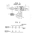
- Fig. 4 is a circuit diagram, partly as a block diagram, showing an example of a space diversity receiving system constructed according to the invention; and
- Fig. 5 is a signal waveform diagram for a description of the operation of a pulse generating circuit in Fig. 4.
- A preferred embodiment of the present invention will be described with reference to Fig. 4, in which circuit elements which have been previously described with reference to Figs. 1 and 3 are designated by the same reference numerals or characters.
- In Fig. 4, the output of the
level detector circuit 7a is applied to the sample and holdcircuits amplifier 12 through acapacitor 11 for transmitting only AC components (noise components) of the signal. In theAGC amplifier 12, the AC components of a level signal supplied thereto, i.e., the level variation component, is amplified at a gain set according to two AGC signals (described below) applied to gain control input terminals thereof. The output of theAGC amplifier 12 is applied to arectifier circuit 13 where the AC component is rectified. The output of therectifier circuit 13 is applied to amonostable multivibrator 14. The output of therectifier circuit 13, after being smoothed by acapacitor 13a serving as a low-pass filter, is fed back, as an AGC signal, to theAGC amplifier 12. The AGC signal is used for separating a noise component for which an antenna switching operation is carried out (as described in detail below). Themonostable multivibrator 14 produces a square-wave signal having a predetermined width when the output of therectifier circuit 13 exceeds the operation start level thereof. The square-wave signal, after being smoothed by acapacitor 14a serving as a low-pass filter, is supplied, as another AGC signal, to theAGC amplifier 12. The square-wave signal is further applied to a differentiating circuit (capacitor) 15, from which the resulting signal is applied as a trigger signal to apulse generating circuit 16. While an AGC gain control signal is applied to theAGC amplifier 12 by themonostable multivibrator 14, the gain of theAGC amplifier 12 is reduced to make the output noise level lower than a predetermined value to prevent the frequency of operation of themonostable multivibrator 14 from exceeding a certain value. - The
pulse generating circuit 16 is formed by cascade-connecting timer circuits such as monostable multivibrators the operation of which is started with the rise of an input trigger signal. Thecircuit 16 provides a gate signal A, an antenna switching signal B, a gate signal C, gate signal D, and a reset signal E successively in response to the trigger signal. The gate signal A is applied to theswitch circuit 53a in the sample and holdcircuit 53. The antenna switching signal B is applied to the antenna switchingdrive circuit 56. The gate signal C is applied to theswitch circuit 54a in the sample and holdcircuit 54. The gate signal D is supplied to aswitch circuit 55a connected between thelevel comparing circuit 55 and the antenna switchingdrive circuit 56. The reset signal E is supplied to resetswitch circuits capacitors circuits - The operation of the space diversity receiving system thus constructed will be described with reference to Fig. 5.
- When noise components are generated by an abrupt change of the received electric field strength or noise components such as white noise are present because the electric field strength is low, the output of the
level detector circuit 7a may include a noise component. The noise component is separated by thecapacitor 11, amplified by theAGC amplifier 12, and then rectified by therectifier circuit 13. When the output of therectifier circuit 13 exceeds a predetermined level, themonostable multivibrator 14 is activated to produce the square-wave signal. The square-wave signal thus produced is differentiated to a differentiation signal, only the positive part of which is used as the trigger signal. - The
AGC amplifier 12 operates as follows: - The gain characteristic of the amplifier is determined by the AGC signal provided by the
rectifier circuit 13 so that, in the presence of a middle or high received electric field strength, thepulse generating circuit 16 is triggered in response to an abrupt change in the electric field strength which may occur in the case of multi-path fading, and when the received signal has a high degree of modulation, the pulse generating circuit is generally not triggered thereby. When the received electric field is low, in which case it is required to select the antenna higher in signal reception level and where it is rather difficult to distinguish multi-path noise from white noise, the AGC signal suspends the AGC operation or weakens it, thereby to increase the gain of the amplifier, whereby the trigger signal is produced at random and continuously. - The gain of the
AGC amplifier 12 is decreased also by the AGC signal provided by themonostable multivibrator 14 in such a manner that the frequency of generation of the trigger signal does not exceed a certain value, that is, so that the antennas are not switched too frequently. This technique is effective especially in the case where the electric field strength is low. - In response to the trigger signal, the
pulse generating circuit 16 produces the signals A through E successively to operate the respective circuit elements so that, of the antennas, the one highest in received electric field strength is selected. This will be described in more detail. - The gate signal A having a predetermined pulse width is applied to the
switch circuit 53a in the sample and holdcircuit 53. As a result, theswitch circuit 53a is held closed for a predetermined period of time so that a level detection output corresponding to the presently selectedantenna 1 is held by the sample and hold circuit. - The antenna switching signal B is supplied to the antenna switching
drive circuit 56 to cause theantenna selecting circuit 3 to select the output of thenext antenna 2. - The gate signal C is applied to the
switch circuit 54b of the sample and holdcircuit 54 so that a level detection output corresponding to theantenna 2 is held by the sample and hold circuit. - The gate signal D is supplied to the
switch circuit 55a. When theswitch circuit 55a is closed, the result of comparison of the levels held by the sample and holdcircuits drive circuit 56 by thelevel comparing circuit 55. In thecircuit 55, the levels held by the sample and holdcircuits circuit 53 is higher than that held by thecircuit 54, thelevel comparing circuit 55 applies a high level signal to the antenna switchingdrive circuit 56. When, on the other hand, the level held by thecircuit 54 is higher than or equal to that held by thecircuit 53, thecircuit 55 applies a low level signal to thecircuit 56. In response to the above-described result of comparison, the antenna switchingdrive circuit 56 causes theantenna selecting circuit 3 to select one of the outputs of theantennas - The reset signal E is applied to the
reset switch circuits hold circuits capacitors - Thus, since the gain of the
AGC amplifier 12 changes with the input level, the output of the AGC amplifier is controlled during the operation of the timer. Therefore, irrespective of the electric field strength, the noise component is suitably detected, and the antenna higher in received electric field strength is selected, which prevents the antennas from being too frequently switched. - In the above embodiment of the invention, two AGC systems are employed. However, the AGC amplifier may be controlled by one of the two AGC systems if desired.
- In the above-described embodiment, in order to detect the noise component included in the received signal, the AC component included in the output of the
level detector circuit 7a is extracted. However, the following method may be employed: A signal FM-detected in the rear state (not shown) is applied to a high-pass filter having a cut-off frequency of the order to 100 KHz to extract a noise component therefrom, and the noise component is applied to the AGC amplifier. The output of the high-pass filter, after being rectified, may be applied to the sampling circuits. - To select the antenna, a microprocessor may be used in combination with the
pulse generating circuit 16, the sample and holdcircuits level comparing circuit 55 and the antenna switchingdrive circuit 56. In this case, the level detection outputs are subjected to A/D (analog-to-digital) conversion so that, in response to the trigger signals, the level detection outputs of the antennas are successively stored in memory, and the largest of the outputs thus stored is extracted to select the corresponding antenna. Furthermore, the following method may be employed: Of the two antennas, the one higher in signal reception level is stored, and the signal reception level of the antenna thus stored is compared with that of the other antenna so that the antenna higher in signal reception level is stored. That is, the outputs of the antennas are subjected to comparison in this manner so that the antennas higher in signal reception level is detected at all times. - Similarly, a microprocessor may be used to form the
AGC amplifier 12, therectifier circuit 13 and themonostable multivibrator 14. With the microprocessor, a circuit for switching a number of antennas can be readily formed at low manufacturing cost. - As described above, in the space diversity receiving system according to the invention, with a middle or high received electric field strength, the search operation is started in response to noise whereby, of a plurality of antennas, the one highest in received electric field strength is selected. Thus, the antenna switching operation is performed only when required, with the result that the antenna switching noise is reduced. With a low received electric field strength, the search operation is carried out in response noise such as a white noise at all times. Thus, the space diversity receiving system of the invention operates suitably with any received electric field strength.
Claims (4)
level detecting means (7a) for detecting a received electric field strength of a selected antenna from among the plurality of antennas;
AC component separating means (11) for separating an AC component from an output of the level detection means;
trigger signal generating means (13,14) for producing a trigger signal when a level of the AC component exceeds a reference value; and
antenna selecting means (53,54) for selecting an antenna presently higher in received electric field strength in response to the trigger signal.
Applications Claiming Priority (2)
| Application Number | Priority Date | Filing Date | Title |
|---|---|---|---|
| JP86084/87 | 1987-04-08 | ||
| JP62086084A JPS63252024A (en) | 1987-04-08 | 1987-04-08 | Space diversity receiver |
Publications (3)
| Publication Number | Publication Date |
|---|---|
| EP0286366A2 true EP0286366A2 (en) | 1988-10-12 |
| EP0286366A3 EP0286366A3 (en) | 1990-02-28 |
| EP0286366B1 EP0286366B1 (en) | 1995-02-22 |
Family
ID=13876838
Family Applications (1)
| Application Number | Title | Priority Date | Filing Date |
|---|---|---|---|
| EP88303040A Expired - Lifetime EP0286366B1 (en) | 1987-04-08 | 1988-04-06 | Space diversity receiving system |
Country Status (4)
| Country | Link |
|---|---|
| US (1) | US4864642A (en) |
| EP (1) | EP0286366B1 (en) |
| JP (1) | JPS63252024A (en) |
| DE (1) | DE3853090D1 (en) |
Cited By (4)
| Publication number | Priority date | Publication date | Assignee | Title |
|---|---|---|---|---|
| GB2246686A (en) * | 1990-08-01 | 1992-02-05 | Mitsubishi Electric Corp | Antenna selecting diversity receiving apparatus |
| US5131006A (en) * | 1990-09-06 | 1992-07-14 | Ncr Corporation | Carrier detection for a wireless local area network |
| US9990791B2 (en) | 2015-12-16 | 2018-06-05 | Matthew Firth | Smart lockbox |
| US11190284B2 (en) | 2019-06-20 | 2021-11-30 | Rohde & Schwarz Gmbh & Co. Kg | Switching system and method for sequential switching of radio frequency paths |
Families Citing this family (17)
| Publication number | Priority date | Publication date | Assignee | Title |
|---|---|---|---|---|
| US5065449A (en) * | 1987-08-03 | 1991-11-12 | Orion Industries | Booster diversity receiving system usable with cellular booster |
| US5168574A (en) * | 1987-08-03 | 1992-12-01 | Orion Industries, Inc. | System and method for switching between antennas in a radio frequency booster |
| US5117505A (en) * | 1990-02-22 | 1992-05-26 | American Nucleonics Corporation | Interference cancellation system having noise reduction features and method |
| US5231273A (en) * | 1991-04-09 | 1993-07-27 | Comtec Industries | Inventory management system |
| JPH0528144U (en) * | 1991-09-18 | 1993-04-09 | パイオニア株式会社 | Receiving machine |
| US5369801A (en) * | 1992-09-25 | 1994-11-29 | Northern Telecom Limited | Antenna diversity reception in wireless personal communications |
| ATE270479T1 (en) * | 1993-09-30 | 2004-07-15 | Skyworks Solutions Inc | BASE STATION FOR A DIGITAL CORDLESS TELEPHONE WITH MULTIPLE ANTENNA ARRANGEMENT |
| US5603107A (en) * | 1995-06-09 | 1997-02-11 | Ford Motor Company | Switching system for diversity antenna FM receiver |
| DE19621206C2 (en) * | 1996-05-25 | 1999-07-08 | Grundig Ag | Method for the interference-free transmission of video signals over a radio transmission link and device for carrying out the method |
| CA2188845A1 (en) * | 1996-10-25 | 1998-04-25 | Stephen Ross Todd | Diversity Antenna Selection |
| SE9702370L (en) * | 1997-06-19 | 1998-12-20 | Ericsson Telefon Ab L M | Balanced diversity |
| US6079367A (en) * | 1997-10-10 | 2000-06-27 | Dogwatch, Inc. | Animal training apparatus and method |
| US5913196A (en) * | 1997-11-17 | 1999-06-15 | Talmor; Rita | System and method for establishing identity of a speaker |
| DE19910571A1 (en) * | 1999-03-10 | 2000-09-14 | Delphi Tech Inc | Radio receiving device |
| IL129451A (en) | 1999-04-15 | 2004-05-12 | Eli Talmor | System and method for authentication of a speaker |
| US6463415B2 (en) | 1999-08-31 | 2002-10-08 | Accenture Llp | 69voice authentication system and method for regulating border crossing |
| EP1150440B1 (en) * | 2000-04-28 | 2006-07-12 | Siemens Aktiengesellschaft | Antenna diversity receiver |
Citations (3)
| Publication number | Priority date | Publication date | Assignee | Title |
|---|---|---|---|---|
| DE3324959A1 (en) * | 1983-07-11 | 1985-01-31 | Sennheiser Electronic Kg, 3002 Wedemark | Receiving circuit for a space diversity method |
| US4525869A (en) * | 1982-04-30 | 1985-06-25 | Clarion Co., Ltd. | Diversity receiver |
| JPS6130137A (en) * | 1984-07-20 | 1986-02-12 | Sanyo Electric Co Ltd | Diversity receiver |
Family Cites Families (5)
| Publication number | Priority date | Publication date | Assignee | Title |
|---|---|---|---|---|
| US4255816A (en) * | 1978-09-15 | 1981-03-10 | Threshold Technology, Inc. | Receiving apparatus having a plurality of antennas |
| JPS5868328A (en) * | 1981-10-19 | 1983-04-23 | Hitachi Ltd | Space diversity reception system |
| JPS5917741A (en) * | 1982-07-21 | 1984-01-30 | Hitachi Ltd | Switching detecting circuit of space diversity receiver |
| JPS5919443A (en) * | 1982-07-23 | 1984-01-31 | Hitachi Ltd | Space diversity receiver |
| JPS6139649A (en) * | 1984-07-30 | 1986-02-25 | Meisei Electric Co Ltd | Receiving system of wireless transmission data |
-
1987
- 1987-04-08 JP JP62086084A patent/JPS63252024A/en active Pending
-
1988
- 1988-04-01 US US07/176,527 patent/US4864642A/en not_active Expired - Fee Related
- 1988-04-06 DE DE3853090T patent/DE3853090D1/en not_active Expired - Lifetime
- 1988-04-06 EP EP88303040A patent/EP0286366B1/en not_active Expired - Lifetime
Patent Citations (3)
| Publication number | Priority date | Publication date | Assignee | Title |
|---|---|---|---|---|
| US4525869A (en) * | 1982-04-30 | 1985-06-25 | Clarion Co., Ltd. | Diversity receiver |
| DE3324959A1 (en) * | 1983-07-11 | 1985-01-31 | Sennheiser Electronic Kg, 3002 Wedemark | Receiving circuit for a space diversity method |
| JPS6130137A (en) * | 1984-07-20 | 1986-02-12 | Sanyo Electric Co Ltd | Diversity receiver |
Non-Patent Citations (2)
| Title |
|---|
| IEEE TRANSACTIONS ON VEHICULAR TECHNOLOGY, vol. VT-22, no. 4, November 1973, pages 185-191, New York, US; W.E. SHORTALL: "A switched diversity receiving system for mobile radio" * |
| PATENT ABSTRACTS OF JAPAN, vol. 10, no. 184 (E-415)[2240], 27th June 1986; & JP-A-61 030 137 (SANYO ELECTRIC CO. LTD) 12-02-1986 * |
Cited By (6)
| Publication number | Priority date | Publication date | Assignee | Title |
|---|---|---|---|---|
| GB2246686A (en) * | 1990-08-01 | 1992-02-05 | Mitsubishi Electric Corp | Antenna selecting diversity receiving apparatus |
| US5241701A (en) * | 1990-08-01 | 1993-08-31 | Mitsubishi Denki Kabushiki Kaisha | Antenna selecting diversity receiving apparatus |
| GB2246686B (en) * | 1990-08-01 | 1994-10-26 | Mitsubishi Electric Corp | Antenna selecting diversity receiving apparatus |
| US5131006A (en) * | 1990-09-06 | 1992-07-14 | Ncr Corporation | Carrier detection for a wireless local area network |
| US9990791B2 (en) | 2015-12-16 | 2018-06-05 | Matthew Firth | Smart lockbox |
| US11190284B2 (en) | 2019-06-20 | 2021-11-30 | Rohde & Schwarz Gmbh & Co. Kg | Switching system and method for sequential switching of radio frequency paths |
Also Published As
| Publication number | Publication date |
|---|---|
| JPS63252024A (en) | 1988-10-19 |
| EP0286366A3 (en) | 1990-02-28 |
| DE3853090D1 (en) | 1995-03-30 |
| US4864642A (en) | 1989-09-05 |
| EP0286366B1 (en) | 1995-02-22 |
Similar Documents
| Publication | Publication Date | Title |
|---|---|---|
| EP0286366B1 (en) | Space diversity receiving system | |
| US4356567A (en) | Radio receiver with bandwidth switching | |
| US5564093A (en) | Frequency modulation receiving apparatus having two intermediate-frequency band pass filters | |
| US4327446A (en) | Noise blanker which tracks average noise level | |
| US4698632A (en) | Radar detector | |
| EP0430468B1 (en) | Signal-to-noise ratio indicating circuit for FM receivers | |
| US4115812A (en) | Automatic gain control circuit | |
| GB2081542A (en) | Portable radio communication device | |
| EP0814570A3 (en) | Receiver with an antenna switch, in which sensitivity and quality of reception is improved | |
| US4584580A (en) | Apparatus for rejecting jamming waves | |
| US3714583A (en) | Muting circuit | |
| US3126514A (en) | John w | |
| GB2078035A (en) | Muting circuits | |
| KR920008266Y1 (en) | Fm interference prevention circuit in six channel of tv receiver | |
| US3968383A (en) | Noise limiter | |
| JPS6137813B2 (en) | ||
| JPS5917740A (en) | Space diversity receiver | |
| JP2983609B2 (en) | Multipath noise reduction circuit | |
| US4680772A (en) | Digital signal repeater including means for controlling a transmitter | |
| JP3143393B2 (en) | AM radio receiver | |
| JPS63252025A (en) | Space diversity receiver | |
| US4282602A (en) | Channel signal detection circuit for scanning receivers | |
| JP2680746B2 (en) | Pulse noise removal circuit | |
| JP2827581B2 (en) | Digital receiver | |
| JP3156599B2 (en) | Receiver |
Legal Events
| Date | Code | Title | Description |
|---|---|---|---|
| PUAI | Public reference made under article 153(3) epc to a published international application that has entered the european phase |
Free format text: ORIGINAL CODE: 0009012 |
|
| AK | Designated contracting states |
Kind code of ref document: A2 Designated state(s): DE FR GB |
|
| PUAL | Search report despatched |
Free format text: ORIGINAL CODE: 0009013 |
|
| AK | Designated contracting states |
Kind code of ref document: A3 Designated state(s): DE FR GB |
|
| 17P | Request for examination filed |
Effective date: 19900809 |
|
| 17Q | First examination report despatched |
Effective date: 19920928 |
|
| GRAA | (expected) grant |
Free format text: ORIGINAL CODE: 0009210 |
|
| AK | Designated contracting states |
Kind code of ref document: B1 Designated state(s): DE FR GB |
|
| PG25 | Lapsed in a contracting state [announced via postgrant information from national office to epo] |
Ref country code: FR Effective date: 19950222 |
|
| REF | Corresponds to: |
Ref document number: 3853090 Country of ref document: DE Date of ref document: 19950330 |
|
| PG25 | Lapsed in a contracting state [announced via postgrant information from national office to epo] |
Ref country code: GB Effective date: 19950522 |
|
| PG25 | Lapsed in a contracting state [announced via postgrant information from national office to epo] |
Ref country code: DE Effective date: 19950523 |
|
| EN | Fr: translation not filed | ||
| PLBE | No opposition filed within time limit |
Free format text: ORIGINAL CODE: 0009261 |
|
| STAA | Information on the status of an ep patent application or granted ep patent |
Free format text: STATUS: NO OPPOSITION FILED WITHIN TIME LIMIT |
|
| GBPC | Gb: european patent ceased through non-payment of renewal fee |
Effective date: 19950522 |
|
| 26N | No opposition filed | ||
| APAH | Appeal reference modified |
Free format text: ORIGINAL CODE: EPIDOSCREFNO |