EP0286558A1 - Method and device for filling cavities - Google Patents
Method and device for filling cavities Download PDFInfo
- Publication number
- EP0286558A1 EP0286558A1 EP88440027A EP88440027A EP0286558A1 EP 0286558 A1 EP0286558 A1 EP 0286558A1 EP 88440027 A EP88440027 A EP 88440027A EP 88440027 A EP88440027 A EP 88440027A EP 0286558 A1 EP0286558 A1 EP 0286558A1
- Authority
- EP
- European Patent Office
- Prior art keywords
- cavity
- resin
- mass
- resins
- light
- Prior art date
- Legal status (The legal status is an assumption and is not a legal conclusion. Google has not performed a legal analysis and makes no representation as to the accuracy of the status listed.)
- Ceased
Links
Images

Classifications
-
- A—HUMAN NECESSITIES
- A61—MEDICAL OR VETERINARY SCIENCE; HYGIENE
- A61C—DENTISTRY; APPARATUS OR METHODS FOR ORAL OR DENTAL HYGIENE
- A61C19/00—Dental auxiliary appliances
- A61C19/003—Apparatus for curing resins by radiation
- A61C19/004—Hand-held apparatus, e.g. guns
-
- A—HUMAN NECESSITIES
- A61—MEDICAL OR VETERINARY SCIENCE; HYGIENE
- A61C—DENTISTRY; APPARATUS OR METHODS FOR ORAL OR DENTAL HYGIENE
- A61C1/00—Dental machines for boring or cutting ; General features of dental machines or apparatus, e.g. hand-piece design
- A61C1/02—Dental machines for boring or cutting ; General features of dental machines or apparatus, e.g. hand-piece design characterised by the drive of the dental tools
- A61C1/07—Dental machines for boring or cutting ; General features of dental machines or apparatus, e.g. hand-piece design characterised by the drive of the dental tools with vibratory drive, e.g. ultrasonic
Abstract
L'invention concerne un procédé pour obturer la cavité d'une dent ou d'un moule, ainsi qu'un outil destiné à la mise en oeuvre du procédé. Le procédé, du type dans lequel on dépose dans la cavité (3) une résine photosensible destinée à être solidifiée par photopolymérisation, est remarquable selon l'invention en ce que - on dépose sur les parois (5, 6) de la cavité (3) une couche (8) d'une première résine photosensible à une première radiation lumineuse ; - on dépose ensuite, sur la couche (8), une masse (10) d'une seconde résine photosensible à une deuxième radiation lumineuse, obturant sensiblement le reste de la cavité (3) ; - on effectue le durcissement par photopolymérisation de ladite masse (10) par la deuxième radiation lumineuse transmise par un bâtonnet (27) plongé dans la masse (10) ; - on effectue ensuite, après le durcissement de la masse (10), le durcissement de la couche (8) de résine photosensible par la première radiation lumineuse à l'aide du bâtonnet (27). Applications : traitement et soins dentaires ainsi que moulage et fonderie de précision.The invention relates to a method for closing the cavity of a tooth or a mold, as well as a tool intended for carrying out the method. The method, of the type in which a photosensitive resin intended to be solidified by photopolymerization is deposited in the cavity (3) is remarkable according to the invention in that - it is deposited on the walls (5, 6) of the cavity (3 ) a layer (8) of a first photosensitive resin to a first light radiation; - Then deposited on the layer (8), a mass (10) of a second photosensitive resin to a second light radiation, substantially closing the rest of the cavity (3); - Hardening is carried out by photopolymerization of said mass (10) by the second light radiation transmitted by a rod (27) immersed in the mass (10); - Then, after the hardening of the mass (10), the hardening of the layer (8) of photosensitive resin is carried out by the first light radiation using the stick (27). Applications: dental treatment and care as well as precision casting and foundry.
Description
La présente invention concerne un procédé de photopolymérisation différentielle à compensation de retrait mettant en oeuvre des résines photosensibles.The present invention relates to a process for differential photopolymerization with shrinkage compensation using photosensitive resins.
Elle concerne plus particulièrement mais non exclusivement un procédé pour obturer une cavité dentaire, ainsi qu'un outil général à main destiné à la mise en oeuvre du procédé.It relates more particularly but not exclusively to a method for closing a dental cavity, as well as a general hand tool intended for the implementation of the method.
Quoique ce procédé soit adapté au domaine de la chirurgie dentaire, on perçoit déjà de nombreuses autres applications industrielles du procédé de l'invention, dans lesquelles on souhaite obturer partiellement ou en totalité une cavité ménagée dans un support quelconque ou mouler un objet ou même le recouvrir de résines photopolymérisables.Although this process is suitable for the field of dental surgery, there are already many other industrial applications of the process of the invention, in which it is desired to partially or completely seal a cavity formed in any support or to mold an object or even the cover with photopolymerizable resins.
L'invention sera décrite ci-après spécifiquement dans le domaine d'application qui concerne la mise en place puis la solidification d'un produit initialement pâteux dans une cavité dentaire.The invention will be described below specifically in the field of application which relates to the establishment and then the solidification of an initially pasty product in a dental cavity.
Elle peut s'appliquer de la même façon à bien d'autres domaines industriels, par exemple à ceux du moulage et de la fonderie de précision notamment au procédé de fonderie dit " à cire perdue " appliqué par example à des pièces de petites tailles.It can be applied in the same way to many other industrial fields, for example to those of molding and precision foundry, in particular to the so-called "lost wax" foundry process applied for example to parts of small sizes.
D'une façon résumée, dans le domaine d'application dentaire pris comme exemple, le traitement notamment des caries dentaires en méthode directe est réalisé fréquemment par l'adjonction d'une résine composite ou d'un amalgame que le praticien dépose dans la cavité préalablement assainie, la solidarisation de l'amalgame étant obtenue par sertissage et/ou par des microrétentions situées sur les parois de la cavité.In summary, in the dental application field taken as an example, the treatment in particular of dental caries in direct method is frequently carried out by the addition of a composite resin or an amalgam which the practitioner deposits in the cavity. previously sanitized, the amalgam joining is obtained by crimping and / or by micro-retentions located on the walls of the cavity.
Dans le cas d'une résine composite esthétique le durcissement est obtenu par polymérisation à l'aide d'un moyen chimique ou par radiation électromagnétique.In the case of an aesthetic composite resin, the hardening is obtained by polymerization using a chemical means or by electromagnetic radiation.
Concernant ce dernier cas, le procédé actuellement utilisé consiste, après avoir assaini les parois de la cavité dentaire à traiter, puis à déposer, en plusieurs couches successives, une masse de résine composite photosensible destinée à obturer ladite cavité, puis à effectuer le durcissement, couche par couche, par photopolymérisation de la résine à l'aide d'une radiation électromagnétique, telle que, par exemple, un rayonnement lumineux issu d'une source de lumière dont la longueur d'onde correspond à la réaction d'initiation et de solidification de la résine.Concerning the latter case, the method currently used consists, after having sanitized the walls of the dental cavity to be treated, then to deposit, in several successive layers, a mass of resin photosensitive composite intended to close said cavity, then to effect curing, layer by layer, by photopolymerization of the resin using electromagnetic radiation, such as, for example, light radiation from a light source, the wavelength corresponds to the initiation and solidification reaction of the resin.
Ce procédé de photopolymérisation présente des avantages appréciables par rapport aux techniques chimiques habituelles encore actuellement pratiquées car il ne requiert plus de la part du praticien une intervention rapide due à la faible durée de prise du durcisseur.This photopolymerization process has appreciable advantages compared to the usual chemical techniques still currently practiced because it no longer requires the practitioner to intervene quickly due to the short setting time of the hardener.
Ces inconvénients n'existent pas avec la technique utilisant une résine photosensible puisque la réaction de photopolymérisation de la résine visqueuse ne commence qu'au moment de la mise en action du rayonnement déclenchée par le praticien.These drawbacks do not exist with the technique using a photosensitive resin since the photopolymerization reaction of the viscous resin does not begin until the action of the radiation initiated by the practitioner.
Cependant, il a été constaté que certains patients traités par cette méthode souffraient de douleurs aiguës car la résine adhère aux parois de la dent, notamment à celles de la chambre pulpaire où se situent les nerfs et les vaisseaux sanguins, et les met sous contrainte lors de sa rétraction. De plus, la polymérisation toujours incomplète en fond de cavité y laisse des monomères libres toxiques pour la pulpe dentaire.However, it has been found that some patients treated with this method suffer from acute pain because the resin adheres to the walls of the tooth, in particular to those of the pulp chamber where the nerves and blood vessels are located, and puts them under stress during of its retraction. In addition, the still incomplete polymerization at the bottom of the cavity leaves free monomers toxic to the dental pulp.
Dans le cas d'applications industrielles, par exemple au domaine du moulage de précision, ce phénomène de retrait bien connu des professionnels, constitue un véritable inconvénient car préjudiciable à la qualité et à la précision des formes et des surfaces moulées.In the case of industrial applications, for example in the field of precision molding, this withdrawal phenomenon well known to professionals, constitutes a real drawback since it is detrimental to the quality and precision of the shapes and of the molded surfaces.
La présente invention a pour but de remédier à ces inconvénients et concerne un procédé de photopolymérisation différentielle à retrait compensé pour le moulage de précision et l'obturation d'une cavité dentaire en une seule fois à partir de résines photopolymérisables, procédé évitant, lors du durcissement de la résine, que les parois de la dent soient sollicitées et qui assure une photomolymérisation complète de la résine.The object of the present invention is to remedy these drawbacks and relates to a process of differential photopolymerization with compensated shrinkage for precision molding and filling of a dental cavity all at once from photopolymerizable resins, a method which avoids, during the hardening of the resin, that the walls of the tooth are stressed and which ensures a complete photopolymerization of the resin.
A cet effet, le procédé de moulage ou d'obturation d'une cavité dentaire du type dans lequel on dépose dans une cavité ou dans un moule une résine photosensible destinée à être solidifiée par photopolymérisation est remarquable, selon l'invention, en ce que :
- on dépose sur les parois de ladite cavité ou moule une couche d'une première résine photosensible ;
- on dépose ensuite, sur ladite couche de la première résine photosensible, une masse d'une seconde résine photosensible obturant le reste de ladite cavité ;
- on effectue le durcissement par photopolymérisation de ladite masse ; et
- on effectue ensuite, après le durcissement de ladite masse, le durcissement de ladite couche de la première résine photosensible.To this end, the method of molding or filling a dental cavity of the type in which a photosensitive resin intended to be solidified by photopolymerization is deposited in a cavity or in a mold is remarkable, according to the invention, in that :
- A layer of a first photosensitive resin is deposited on the walls of said cavity or mold;
- Then deposited on said layer of the first photosensitive resin, a mass of a second photosensitive resin sealing the rest of said cavity;
- Hardening is carried out by photopolymerization of said mass; and
- Then, after the hardening of said mass, the hardening of said layer of the first photosensitive resin is carried out.
Ainsi, grâce à l'invention, le retrait lors du durcissement de la masse de la seconde résine photosensible occupant la majeure partie du volume défini par la cavité ou le moule n'agit pas directement sur les parois mêmes de ladite cavité ou dudit moule, puisque la couche de la première résine, déposée entre ces parois et la masse de résine, est encore visqueuse et fait office par conséquent de couche tampon. On effectue, seulement après le durcissement de ladite masse, le durcissement de ladite couche de première résine dont la faible épaisseur déposée sur les parois de ladite cavité n'exerce pas, lors de sa solidification, des tractions suffisantes sur les parois pour provoquer des douleurs ou des variations dimensionnelles de forme ou de surface.Thus, thanks to the invention, the shrinkage during hardening of the mass of the second photosensitive resin occupying most of the volume defined by the cavity or the mold does not act directly on the very walls of said cavity or said mold, since the layer of the first resin, deposited between these walls and the resin mass, is still viscous and therefore acts as a buffer layer. Is carried out, only after the hardening of said mass, the hardening of said layer of first resin whose thin thickness deposited on the walls of said cavity does not exert, during its solidification, sufficient traction on the walls to cause pain or dimensional variations in shape or surface.
Par ailleurs, chacune des première et seconde résines réagissant à une radiation électromagnétique de photopolymérisation de longueur d'onde optimale et spécifique,
- on choisit, de préférence, les deux résines de façon que la radiation destinée à photopolymériser la masse de seconde résine n'agisse pas sur la couche de première résine ;
- on applique alors la radiation électromagnétique correspondant à la longueur d'onde optimale de photopolymérisation de la seconde résine à l'ensemble desdites résines déposées dans ladite cavité ; puis,
- après durcissement de ladite seconde résine, on applique la radiation électromagnétique de longueur d'onde optimale appropriée pour photopolymériser ladite première résine.Furthermore, each of the first and second resins reacting to electromagnetic radiation from photopolymerization of optimum and specific wavelength,
- preferably, the two resins are chosen so that the radiation intended to photopolymerize the mass of second resin does not act on the layer of first resin;
- The electromagnetic radiation corresponding to the optimal photopolymerization wavelength of the second resin is then applied to all of said resins deposited in said cavity; then,
- After hardening of said second resin, electromagnetic radiation of optimum wavelength suitable for photopolymerizing said first resin is applied.
Ainsi, le procédé selon l'invention consiste à réaliser une photopolymérisation différentielle desdites résines permettant d'obtenir une réduction importante du retrait.Thus, the method according to the invention consists in carrying out a differential photopolymerization of said resins making it possible to obtain a significant reduction in shrinkage.
De plus, préalablement au dépôt de la couche constituée de la première résine photosensible et après avoir préparé la cavité de la dent ou du moule avec un gel acide, on enduit les parois de ladite cavité ou du moule d'un agent de liaison permettant la solidarisation de la résine auxdites parois.In addition, before depositing the layer consisting of the first photosensitive resin and after having prepared the cavity of the tooth or of the mold with an acid gel, the walls of said cavity or of the mold are coated with a bonding agent allowing the attachment of the resin to said walls.
La présente invention concerne également un outil à main destiné à la mise en oeuvre du procédé.The present invention also relates to a hand tool intended for implementing the method.
A cet effet, l'outil à main, selon l'invention, du type comprenant un corps sensiblement tubulaire présentant une tête à une extrémité est caractérisé en ce qu'il comporte, dans ledit corps, des moyens pour la transmission de radiations électromagnétiques lumineuses émises par une source lumineuse susceptible d'être raccordée à l'autre extrémité du corps, les moyens de transmission émergeant de la tête pour pénétrer dans les résines déposées dans la cavité de sorte que, en fonction de la longueur d'onde règlable des radiations émises, soit obtenu le durcissement par photopolymérisation de chacune des résines photosensibles.To this end, the hand tool, according to the invention, of the type comprising a substantially tubular body having a head at one end is characterized in that it comprises, in said body, means for the transmission of light electromagnetic radiation. emitted by a light source capable of being connected to the other end of the body, the transmission means emerging from the head to penetrate the resins deposited in the cavity so that, depending on the adjustable wavelength of the radiations emitted, or obtained the curing by photopolymerization of each of the photosensitive resins.
Dans une forme préférée de réalisation, lesdits moyens pour la transmission des radiations sont constitués par une fibre optique logée dans ledit corps tubulaire et couplée par une extrémité à ladite source lumineuse, et par un bâtonnet photodistributeur à usage unique maintenu dans la tête en émergeant en partie de celle-ci, le bâtonnet, qui reçoit et transmet les radiations émises par la fibre optique, étant susceptible d'être introduit dans les résines déposées dans ladite cavité. Ainsi, après que la partie émergeante du bâtonnet ait été plongée jusqu'au voisinage du fond de la cavité dentaire ou du moule contenant les résines, la source lumineuse commandée par le praticien émet une radiation électromagnétique dont la longueur d'onde correspond à la réaction de photopolymérisation de la seconde résine, mais qui n'agit pas sur la couche constituée de la première résine qui reste alors visqueuse compensant ainsi la diminution de volume de la masse de seconde résine. Après le durcissement total de ladite masse, une radiation électromagnétique émise par la source lumineuse et dont la longueur d'onde correspond alors à la réaction de photopolymérisation de la première résine, permet la solidification de celle-ci, la partie émergeante du bâtonnet étant emprisonnée dans la masse solidifiée de seconde résine.In a preferred embodiment, said means for transmitting radiation consists of an optical fiber housed in said tubular body and coupled at one end to said light source, and by a single-use photodistributor stick maintained in the head, partly emerging therefrom, the rod, which receives and transmits the radiation emitted by the optical fiber, being capable of being introduced into the resins deposited in said cavity. Thus, after the emerging part of the stick has been plunged to the vicinity of the bottom of the dental cavity or of the mold containing the resins, the light source controlled by the practitioner emits electromagnetic radiation whose wavelength corresponds to the reaction photopolymerization of the second resin, but which does not act on the layer consisting of the first resin which then remains viscous thus compensating for the decrease in volume of the mass of second resin. After the total hardening of said mass, electromagnetic radiation emitted by the light source and the wavelength of which then corresponds to the photopolymerization reaction of the first resin, allows it to solidify, the emerging part of the stick being trapped in the solidified mass of second resin.
Lorsque le durcissement de la première résine est obtenu, le bâtonnet est désolidarisé de l'outil, puis sectionné au niveau de la face supérieure de la dent ou du moule.When the hardening of the first resin is obtained, the stick is detached from the tool, then sectioned at the level of the upper face of the tooth or of the mold.
Une opération de polissage termine alors le traitement ou le moulage.A polishing operation then completes the treatment or molding.
Avantageusement, une cellule photoélectrique est prévue sur la tête, en étant disposée en regard desdites résines. Ainsi, la cellule, reliée à la source lumineuse, permet par l'intermédiaire d'un dispositif électronique de commande le changement de longueur d'onde de la radiation électromagnétique émise, lorsque l'opacité de la seconde résine, qui se modifie au cours de la solidification passant de l'état pâteux à l'état solide correspond au durcissemnt complet de cette résine.Advantageously, a photoelectric cell is provided on the head, being arranged opposite said resins. Thus, the cell, connected to the light source, makes it possible, via an electronic control device, to change the wavelength of the electromagnetic radiation emitted, when the opacity of the second resin, which changes during solidification passing from the pasty state to the solid state corresponds to the complete hardening of this resin.
Par ailleurs, afin de faciliter l'opération de montage et de démontage du bâtonnet à usage unique sur l'outil, le bâtonnet est inséré à force dans un perçage ménagé dans ladite tête.Furthermore, in order to facilitate the assembly and disassembly operation of the disposable stick on the tool, the stick is inserted by force into a hole made in said head.
De plus, une partie du bâtonnet restant solidaire desdites résines, celui-ci est de préférence réalisé dans une résine translucide dont les caractéristiques sont compatibles avec celles des résines déposées dans ladite cavité.In addition, part of the stick remaining integral with said resins, it is preferably made of a translucent resin whose characteristics are compatible with those of the resins deposited in said cavity.
Dans un mode préféré de réalisation une optique de focalisation des radiations électromagnétiques est agencée entre la sortie de la fibre optique et le bâtonnet, ce dernier, disposé transversalement par rapport à la direction de la fibre optique, venant au contact d'un réflecteur fixé à ladite tête. On prévoit avantageusement un élément ménagé dans la tête et entourant le bâtonnet, l'élément piézoélectrique engendrant des vibrations qui ont pour effet de tasser les résines par l'intermédiaire du bâtonnet.In a preferred embodiment an optic for focusing electromagnetic radiation is arranged between the outlet of the optical fiber and the rod, the latter, the latter arranged transversely to the direction of the optical fiber, coming into contact with a reflector fixed to said head. An element formed in the head and surrounding the rod is advantageously provided, the piezoelectric element generating vibrations which have the effect of packing the resins by means of the rod.
Enfin, selon une autre caractéristique de l'invention, afin d'assurer le nettoyage de la dent traitée, ou du moule de précision, ainsi que celui des parties avoisinantes, des conduites respectivement d'arrivée d'air et d'arrivée d'eau peuvent être fixées audit corps.Finally, according to another characteristic of the invention, in order to ensure the cleaning of the treated tooth, or of the precision mold, as well as that of the neighboring parts, the air inlet and air inlet pipes respectively. water can be attached to said body.
Les figures du dessin annexé feront bien comprendre comment l'invention peut être réalisée dans le cas d'une application au domaine dentaire.
- . Les figures 1, 2, 3, 4 et 5 illustrent schématiquement les différentes étapes du procédé selon l'invention destiné à obturer une cavité ou un moule.
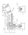
- . La figure 6 représente, partiellement en coupe et schématiquement, un outil à main selon l'invention destiné à la mise en oeuvre du procédé, ledit outil étant montré dans l'étape du procédé correspondant à la photopolymérisation desdites résines.
- . La figure 7 est une vue en coupe schématique d'une dent traitée selon le procédé de l'invention au moyen de l'outil à main prévu à cet effet.
- . Figures 1, 2, 3, 4 and 5 schematically illustrate the different stages of the method according to the invention intended to close a cavity or a mold.
- . FIG. 6 represents, partially in section and schematically, a hand tool according to the invention intended for the implementation of the process, said tool being shown in the process step corresponding to the photopolymerization of said resins.
- . Figure 7 is a schematic sectional view of a tooth treated according to the method of the invention by means of the hand tool provided for this purpose.
Le procédé illustré par les figures 1 à 5 consiste à obturer une cavité ménagée dans une dent ou dans un moule mais d'autres applications différentes ou analogues sont visées par la présente invention.The process illustrated in FIGS. 1 to 5 consists in closing a cavity formed in a tooth or in a mold but other different applications or analogs are covered by the present invention.
La forme schématique représentée sur les figures illustre aussi bien une dent vue en coupe qu'un moule de précision.The schematic form shown in the figures illustrates both a tooth seen in section and a precision mold.
Pour les besoins de la description ci-dessous, on imaginera la forme représentée comme étant celle d'une dent. Elle pourra aussi bien être celle d'un moule de précision.For the purposes of the description below, imagine the shape shown as being that of a tooth. It could as well be that of a precision mold.
On décrira ci-après le procédé de photopolymérisation selon l'invention appliqué à la cavité d'une dent. Le même procédé s'applique tout aussi bien à toute autre cavité notamment celle d'un moule de précision.The photopolymerization process according to the invention applied to the cavity of a tooth will be described below. The same process applies just as well to any other cavity, in particular that of a precision mold.
Une dent 1 implantée dans la gencive 2 présente une cavité 3 qui débouche, pour cet exemple, dans la face occlusiale 4 de la dent et est définie par ses parois latérales 5 et son fond 6.A
Le praticien procède préalablement notamment à l'assainissement des parois 5 et du fond 6 de la cavité 3 de façon connue. Après avoir traité l'émail de la cavité avec un gel acide, il enduit ensuite, figure 2, les parois latérales 5 et le fond 6 d'un agent de liaison 7 ou adhésif destiné à solidariser, comme on le verra ultérieurement, les résines aux parois et au fond de la cavité 3 de la dent ou du moule, l'agent de liaison pouvant être un amélodentinocène.The practitioner proceeds beforehand in particular to the cleaning of the
Il dépose alors, figure 3, sur ledit agent de liaison 7, une couche d'une première résine photosensible 8 d'un type connu en soi. La couche 8 déborde de la cavité 3 de la dent ou du moule, comme le montre de manière accentuée la figure 3, de façon qu'une bordure latérale 9 de la couche 8 repose sur la face masticatrice 4 de la dent.He then deposits, in FIG. 3, on said
Puis, le praticien dépose sur la couche 8, figure 4, une masse d'une seconde résine photosensible 10 obturant sensiblement le reste de la cavité 3 de la dent ou du moule. Le volume de la masse de seconde résine 10 déposé correspond approximativement au volume de la cavité 3 de la dent ou du moule à obturer.Then, the practitioner deposits on the
Chacune desdites première et seconde résines photosensibles constituant respectivement la couche 8 et la masse 10 est choisie pour réagir à des radiations électromagnétiques de photopolymérisation de longueur d'onde optimale spécifique ou retardataire. Ainsi, la première résine photosensible réagira sous l'action de radiations électromagnétiques dont la longueur d'onde correspond au durcissement par photopolymérisation de cette première résine, tandis que la seconde résine réagira sous l'action de radiations électromagnétiques dont la longueur d'onde, différente de celle initiant la première résine, correspond au durcissement par photopolymérisation de cette seconde résine.Each of said first and second photosensitive resins constituting respectively the
Le praticien effectue alors le durcissement par photopolymérisation de la masse de seconde résine photosensible 10, laquelle sous l'action du rayonnement électromagnétique, par exemple du type lumineux, passe d'un état visqueux à un état solide. Durant la phase de solidification de la seconde résine, la première résine photosensible est toujours dans un état visqueux puisqu'elle ne réagit pas aux rayons électromagnétiques de longueur d'onde spécifique correspondant à la photopolymérisation de la seconde résine. La couche 8 fait alors office de couche intermédiaire tampon. La diminution de volume de la masse 10 de seconde résine est compensée par la couche de première résine 8 réalisant ainsi un retrait différencié puisque l'excès de celle-ci correspondant à la bordure latérale 9 déposée sur la face 4 de la dent ou du moule, s'écoule alors entre la masse 10 solidifiée et le revêtement de liaison 7. En conséquence, la masse 10 est totalement isolée des parois et du fond de la cavité 3, notamment de la chambre pulpaire dans le cas d'une dent, ce qui n'affecte pas les nerfs situés dans la chambre.The practitioner then performs the curing by photopolymerization of the mass of second
Après le durcissement total de la seconde résine, le praticien effectue, au moyen des rayons électromagnétiques de longueur d'onde spécifique (différente de celle correspondant à l'initiation de la seconde résine), le durcissement par photopolymérisation de la couche 8 de la première résine. De par la faible épaisseur de la couche 8 déposée sur les parois 5 et le fond 6 de la cavité dentaire 3 par l'intermédiaire du revêtement de liaison 7, cette fine couche 8 n'exerce pas, lors de sa solidification sous l'action des rayons lumineux, des tractions suffisantes sur les parois de la dent ou du moule, notamment la chambre pulpaire, pour provoquer alors des douleurs éventuelles. En effet, le volume de la cavité 3 de la dent ou du moule est pratiquement en totalité obturé par la masse 10 déjà solidifiée.After the second resin has completely hardened, the practitioner uses electromagnetic rays of specific wavelength (different of that corresponding to the initiation of the second resin), the curing by photopolymerization of the
Puis, lorsque la couche 8 est complètement solidifiée et collée aux parois 5 et au fond 6 de la cavité 3 grâce au revêtement de liaison 7, le praticien effectue des opérations d'ébavurage, de polissage et de nettoyage sur la face desdites résines durcies afin de mettre en conformité cette surface avec celle définie par la face masticatrice 4 (figure 5).Then, when the
Ainsi, grâce au procédé de l'invention, on réalise une photopolymérisation dite différentielle, éliminant par compensation les forces de traction dues au retrait de volume des résines photosensibles lors de l'opération de solidification.Thus, thanks to the process of the invention, a so-called differential photopolymerization is carried out, by compensating for the traction forces due to the volume shrinkage of the photosensitive resins during the solidification operation.
L'invention concerne également un outil à main destiné à la mise en oeuvre du procédé ci-dessus décrit.The invention also relates to a hand tool intended for implementing the method described above.
L'outil à main 15, montré sur la figure 6, comprend un corps 16 sensiblement de forme tubulaire présentant une tête 17 à une extrémité 19, l'autre extrémité du corps 16 n'étant pas illustrée. Le corps tubulaire présente un passage interne 20 débouchant dans un perçage 21 ménagé dans ladite tête 17 et de direction perpendiculaire au passage 20.The
Des moyens 23 pour la transmission de radiations électromagnétiques lumineuses émises par une source lumineuse 24 sont disposés dans le corps 16. Ces moyens 23 sont reliés, par l'extrémité non représentée dudit corps 16, à la source lumineuse 24, cohérente ou non, telle, par exemple, un laser à argon. Ces moyens font saillie au-delà de la tête 17 pour pénétrer, comme on le verra ultérieurement, dans les résines photosensibles activées différentiellement déposées dans la cavité dentaire 3 ou dans le moule.Means 23 for the transmission of light electromagnetic radiation emitted by a
Dans ce mode de réalisation, les moyens 23 sont constitués par une fibre optique 26 et par un bâtonnet 27 photodistributeur réalisé en une matière translucide.In this embodiment, the
L'extrémité de ce bâtonnet affecte une forme telle qu'elle permette une distribution uniforme de l'énergie lumineuse dans tout le volume occupé par la seconde résine c'est-à-dire la masse 10. De plus, cette forme d'extrémité doit permettre d'éviter la formation de bulles lors de sa pénétration dans la masse 10.The end of this rod has a shape such that it allows a uniform distribution of the light energy throughout the volume occupied by the second resin, that is to say the
Ce bâtonnet est à usage unique, c'est-à-dire perdu car comme on le verra ci-après, son extrémité reste définitivement inclue dans la masse 10 de résine. Son rôle essentiel est de distribuer uniformément spatiallement l'énergie des radiations lumineuses de manière à obtenir le meilleur effet possible de photopolymérisation dans le volume dans lequel il est plongé. La fibre optique 26 est logée et maintenue dans le passage interne 20 du corps 16, et est couplée par son entrée, non représentée, à la source lumineuse 24, tandis que la sortie 28 de la fibre optique est située en regard du perçage 21, la fibre optique étant disposée dans une direction sensiblement perpendiculaire à celui-ci. Le bâtonnet 27 est, quant à lui, disposé dans le perçage 21 en étant, dans ce mode particulier de réalisation, inséré à force dans celui-ci. Le bâtonnet 27 présente une extrémité 33 de forme par exemple cylindro-conique qui émerge de la tête 17.This stick is for single use, that is to say lost because as will be seen below, its end remains definitively included in the mass of resin. Its essential role is to uniformly distribute the energy of light radiation spatially so as to obtain the best possible photopolymerization effect in the volume in which it is immersed. The
De plus, il est également prévu, dans l'outil 15, d'une part, une optique de focalisation telle qu'une lentille 34 agencée entre la sortie 28 de la fibre optique 826 et le bâtonnet 27 et, d'autre part, un réflecteur 35 disposé en regard de la lentille 34 en étant incliné de 45°. Le bâtonnet 27 vient s'appuyer par une extrémité taillée en pan incliné 30 contre le réflecteur 35, de sorte que, lorsqu'un rayonnement lumineux est issu de la sortie 28 de la fibre, celui-ci soit focalisé par la lentille 34, puis réfléchi par le réflecteur 35 dans la direction axiale du bâtonnet 27.In addition, there is also provided, in the
Une cellule photoélectrique 37 est fixée sur la face 38 de la tête 17, de façon à être orientée en regard des résines déposées dans la cavité 3. Cette cellule 37 est raccordée par une liaison 39 à un dispositif électronique de commande 36, lui-même relié par une liaison 42 à la source lumineuse 24. Aussi prévoit-on, dans le perçage 21 ménagé dans la tête 17, un évidement torique 40 destiné à recevoir un élément piézo-électrique 41. Les fonctions de la cellule 37 et de l'élément piézo-électrique 41 seront décrites ci-après.A
Enfin, des conduites, respectivement d'arrivée d'eau 43, et d'arrivée d'air 44, sont fixées au corps 16, chaque orifice de sortie débouchant au niveau de la face 38 de la tête 17.Finally, pipes, respectively for the
Le praticien met en place le bâtonnet 27 à usage unique dans le perçage 21 ménagé dans la tête, de façon que le pan incliné 30 vienne correctement en appui contre le réflecteur 35. Le bâtonnet, emmanché à force, est réalisé en une résine translucide compatible avec celles déposées préalablement dans la cavité 3, ou, dans un autre mode d'exécution, le bâtonnet peut être réalisé en verre coulé.The practitioner places the
L'outil 15 est raccordé par l'intermédiaire de la fibre optique 26 à la source lumineuse 24. Après la mise en fonctionnement de cette dernière, le praticien plonge dans la masse 10 la partie cylindro-conique émergente 33 du bâtonnet 27 de façon que sa face d'extrémité 45, parfaitement polie, soit située au voisinage du fond 6 de la cavité 3 contenant la masse 10 de seconde résine et la couche 8 de première résine. La source lumineuse 24, commandée par le praticien, émet alors, après sélection, filtrage ou autre, une radiation électromagnétique correspondant à l'une des couleurs du spectre visible. La longueur d'onde du rayonnement lumineux correspond à la réaction de photopolymérisation de la masse 10 de seconde résine. Ce rayonnement lumineux traverse alors les moyens 23, c'est-à-dire la fibre optique 26, la lentille de focalisation 34 puis se réfléchit grâce au réflecteur 35 dans la direction du bâtonnet 27 pour déboucher par la face d'extrémité 45 de l'extrémité émergeante 33 du bâtonnet 27 dans les résines photosensibles.The
La réaction de photopolymérisation de la masse 10 de seconde résine photosensible commence alors.The photopolymerization reaction of the
Avantageusement, l'élément piézo-électrique 41 engendre des vibrations transmises par le bâtonnet 27 à la masse de résines, qui ont pour effet de tasser notamment la masse de seconde résine. Durant le changement d'état de celle-ci, passant de l'état pâteux ou visqueux à l'état solide, l'opacité de la masse 10 de seconde résine varie. Cette variation d'opacité est détectée par la cellule photoélectrique 37. Ainsi, lorsque l'opacité de la masse 10 de seconde résine correspond à la solidification totale de celle-ci, la cellule photoélectrique 37 émet un signal, transmis par la liaison 39, au dispositif électronique de commande 36 relié à la source 24. Ce dispositif de commande déclenche automatiquement le changement ou modifie la sélection de longueur d'onde du rayonnement lumineux émis. La nouvelle longueur d'onde spécifique, en service ou sélectionnée, correspond alors à la réaction de photopolymérisation de la couche 8 de première résine photosensible, change de couleur.Advantageously, the
La première résine, isolant la masse 10 de seconde résine des parois et du fond de la cavité, durcit jusqu'à atteindre sa solidification totale.The first resin, insulating the mass of second resin from the walls and the bottom of the cavity, hardens until it reaches its total solidification.
Dans ce procédé, l'énergie d'activation destinée à photopolymériser la masse de seconde résine est inférieure à l'énergie d'activation destinée à photopolymériser la couche de première résine.In this process, the activation energy intended to photopolymerize the mass of second resin is less than the activation energy intended to photopolymerize the layer of first resin.
Le praticien arrête le fonctionnement de la source lumineuse 24. L'extrémité émergente 33 est alors partiellement emprisonnée et solidarisée à la masse 10 de seconde résine.The practitioner stops the operation of the
Le praticien désolidarise alors le bâtonnet 27 à usage unique de l'outil à main 15, le bâtonnet se trouvant en partie inséré dans les résines durcies. A l'aide d'une pince coupante ou d'un outil analogue, le praticien sectionne, au ras de la face supérieure, le partie émergeante du bâtonnet. Puis, une opération d'ébavurage classique, terminée par une opération de polissage, achèvent le traitement complet. Le nettoyage de celle-ci ainsi que des parties avoisinantes est assuré par les conduites d'arrivée d'air 44 et d'eau 43.The practitioner then separates the single-
La dent ainsi traitée ou le moule garni par le procédé de l'invention mis en oeuvre par l'outil spécifique, est illustrée schématiquement en regard de la figure 7.The tooth thus treated or the mold filled by the method of the invention implemented by the specific tool, is illustrated diagrammatically with reference to FIG. 7.
L'emploi de deux résines autocalcinables et photopolymérisables, à deux radiations lumineuses de longueur d'onde différentes, permet de viser des applications en fonderie de précision. En effet, les résines autocalcinables actuelles ne laissant aucun résidu apparent, l'utilisation du procédé de coulage ou de moulage dit "à cire perdue" permet de réaliser, avec une grande précision, grâce à la présente invention, des formes creuses notamment sur des pièces de petites tailles.The use of two self-calcining and photopolymerizable resins, with two light radiations of different wavelength, makes it possible to target applications in precision foundry. Indeed, current self-burning resins leaving no apparent residue, the use of the casting or molding process called "lost wax" allows to achieve, with great precision, thanks to the present invention, hollow shapes especially on small parts.
Claims (10)
Applications Claiming Priority (2)
| Application Number | Priority Date | Filing Date | Title |
|---|---|---|---|
| FR8704230 | 1987-03-26 | ||
| FR8704230A FR2612764B1 (en) | 1987-03-26 | 1987-03-26 | METHOD FOR SEALING A DENTAL CAVITY AND TOOL FOR IMPLEMENTING THE METHOD |
Publications (1)
| Publication Number | Publication Date |
|---|---|
| EP0286558A1 true EP0286558A1 (en) | 1988-10-12 |
Family
ID=9349460
Family Applications (1)
| Application Number | Title | Priority Date | Filing Date |
|---|---|---|---|
| EP88440027A Ceased EP0286558A1 (en) | 1987-03-26 | 1988-03-25 | Method and device for filling cavities |
Country Status (4)
| Country | Link |
|---|---|
| US (1) | US5007837A (en) |
| EP (1) | EP0286558A1 (en) |
| JP (1) | JPS6415037A (en) |
| FR (1) | FR2612764B1 (en) |
Cited By (3)
| Publication number | Priority date | Publication date | Assignee | Title |
|---|---|---|---|---|
| US4957441A (en) * | 1988-12-20 | 1990-09-18 | Minnesota Mining And Manufacturing Company | Method of enhancing the curing of a photocurable dental restorative material |
| WO1997037611A1 (en) * | 1996-04-04 | 1997-10-16 | Peter Rechmann | Device and process for curing a photocurable plastic filler |
| EP0830850A1 (en) * | 1996-09-20 | 1998-03-25 | Kuraray Co., Ltd. | Method of polymerizing photo-polymerizable composition for dental use and dental light-curing apparatus for use therewith |
Families Citing this family (48)
| Publication number | Priority date | Publication date | Assignee | Title |
|---|---|---|---|---|
| US5115307A (en) * | 1987-03-05 | 1992-05-19 | Fuji Optical Systems | Electronic video dental camera |
| DE68922497T2 (en) * | 1988-08-24 | 1995-09-14 | Marvin J Slepian | ENDOLUMINAL SEAL WITH BISDEGRADABLE POLYMERS. |
| FR2640537B1 (en) * | 1988-12-21 | 1992-02-21 | Levy Guy | INSTALLATION AND METHOD USING THE LASER EFFECT FOR CUTTING OR VAPORIZING VARIOUS MATERIALS AND FABRICS |
| US5147203A (en) * | 1991-07-30 | 1992-09-15 | Seidenberg Jack W | Air/water delivery system for use with dental illumination devices |
| DE4133109C1 (en) * | 1991-10-05 | 1993-02-25 | Peter Prof. Dr. 5300 Bonn De Thiel | Dental hand instrument for light-hardening fillings - has narrowed end with light transparent section for insertion into filling material |
| JP4564596B2 (en) * | 1992-04-30 | 2010-10-20 | ユーシーエル ビジネス ピーエルシー | Laser treatment |
| US5284443A (en) * | 1992-08-28 | 1994-02-08 | Coltene/Whaledent, Inc. | Method of forming dental restorations |
| GB9309397D0 (en) * | 1993-05-07 | 1993-06-23 | Patel Bipin C M | Laser treatment |
| US5420768A (en) * | 1993-09-13 | 1995-05-30 | Kennedy; John | Portable led photocuring device |
| US6371763B1 (en) * | 1997-11-28 | 2002-04-16 | Robert J. Sicurelli, Jr. | Flexible post in a dental post and core system |
| US5741139A (en) * | 1993-09-27 | 1998-04-21 | Tru-Flex Post Systems, Inc. | Flexible post in a dental post and core system |
| US5503559A (en) * | 1993-09-30 | 1996-04-02 | Cedars-Sinai Medical Center | Fiber-optic endodontic apparatus and method |
| FR2730627B1 (en) * | 1995-02-17 | 1997-07-25 | Marc Reynaud | SELF-LOCKING DENTAL REINFORCEMENT |
| US5807101A (en) * | 1996-01-17 | 1998-09-15 | Scalzo; Josephine | Universal occlusal matrix |
| US5927983A (en) * | 1996-07-29 | 1999-07-27 | Hughes; Michael F. | Intracoronal bristle brush |
| JPH1097166A (en) * | 1996-09-20 | 1998-04-14 | Fuji Xerox Co Ltd | Cleaning device |
| US6201880B1 (en) | 1996-12-31 | 2001-03-13 | Electro-Optical Sciences | Method and apparatus for electronically imaging a tooth through transillumination by light |
| US6008264A (en) * | 1997-04-30 | 1999-12-28 | Laser Med, Inc. | Method for curing polymeric materials, such as those used in dentistry, and for tailoring the post-cure properties of polymeric materials through the use of light source power modulation |
| US6282013B1 (en) | 1997-04-30 | 2001-08-28 | Lasermed, Inc. | System for curing polymeric materials, such as those used in dentistry, and for tailoring the post-cure properties of polymeric materials through the use of light source power modulation |
| US5791898A (en) * | 1997-06-23 | 1998-08-11 | Denbur, Inc. | Light prism for apparatus dental filling |
| GB2329756A (en) * | 1997-09-25 | 1999-03-31 | Univ Bristol | Assemblies of light emitting diodes |
| US6602074B1 (en) | 1997-10-29 | 2003-08-05 | Bisco, Inc. | Dental composite light curing system |
| US6116900A (en) * | 1997-11-17 | 2000-09-12 | Lumachem, Inc. | Binary energizer and peroxide delivery system for dental bleaching |
| US6200134B1 (en) * | 1998-01-20 | 2001-03-13 | Kerr Corporation | Apparatus and method for curing materials with radiation |
| US6157661A (en) * | 1999-05-12 | 2000-12-05 | Laserphysics, Inc. | System for producing a pulsed, varied and modulated laser output |
| WO2001017454A1 (en) * | 1999-09-09 | 2001-03-15 | Rainer Tilse | Method and instrument for introducing a dental filling material with a synthetic-resin base into a tooth cavity |
| US7320593B2 (en) | 2000-03-08 | 2008-01-22 | Tir Systems Ltd. | Light emitting diode light source for curing dental composites |
| WO2002033312A2 (en) * | 2000-10-19 | 2002-04-25 | Reipur Technology A/S | A light-emitting assembly |
| US7134875B2 (en) * | 2002-06-28 | 2006-11-14 | 3M Innovative Properties Company | Processes for forming dental materials and device |
| AU2003265308A1 (en) | 2002-07-25 | 2004-02-16 | Jonathan S. Dahm | Method and apparatus for using light emitting diodes for curing |
| US7182597B2 (en) * | 2002-08-08 | 2007-02-27 | Kerr Corporation | Curing light instrument |
| AU2003298561A1 (en) * | 2002-08-23 | 2004-05-13 | Jonathan S. Dahm | Method and apparatus for using light emitting diodes |
| WO2004071326A1 (en) * | 2003-02-13 | 2004-08-26 | Dentsply International Inc. | Application of dental materials to the oral cavity |
| CA2589570C (en) * | 2004-06-15 | 2010-04-13 | Henkel Corporation | High power led electro-optic assembly |
| CA2585755C (en) * | 2004-10-28 | 2013-02-26 | Henkel Corporation | Led assembly with led-reflector interconnect |
| DE102005019386B4 (en) * | 2005-04-26 | 2010-07-29 | Ivoclar Vivadent Ag | Apparatus for polymerizing polymerizable dental material and method for determining the degree of polymerization |
| US8113830B2 (en) * | 2005-05-27 | 2012-02-14 | Kerr Corporation | Curing light instrument |
| WO2007045249A1 (en) * | 2005-10-19 | 2007-04-26 | Dentofit A/S | A dental handpiece |
| US8047686B2 (en) * | 2006-09-01 | 2011-11-01 | Dahm Jonathan S | Multiple light-emitting element heat pipe assembly |
| DE102007022205A1 (en) * | 2007-05-11 | 2008-11-13 | Kaltenbach & Voigt Gmbh | Hand-held device for dispensing a pasty filling material |
| GB0810384D0 (en) * | 2008-06-06 | 2008-07-09 | 3M Innovative Properties Co | Powder jet device for applying dental material |
| US9072572B2 (en) | 2009-04-02 | 2015-07-07 | Kerr Corporation | Dental light device |
| US9066777B2 (en) | 2009-04-02 | 2015-06-30 | Kerr Corporation | Curing light device |
| EP2550928B1 (en) | 2011-07-25 | 2017-03-01 | Ivoclar Vivadent AG | Dental oven with a drying sensor |
| US10111282B2 (en) * | 2011-07-25 | 2018-10-23 | Ivoclar Vivadent Ag | Dental furnace |
| US8992224B2 (en) * | 2012-08-15 | 2015-03-31 | Kerrhawe Sa | Scanning polymerization of dental material |
| JP2020529873A (en) * | 2017-02-22 | 2020-10-15 | インター—メッド インク | Heating of dental materials using overtone features, dye absorption, and material properties |
| WO2022189891A1 (en) * | 2021-03-12 | 2022-09-15 | Solcarry Ltd. | Treating dental caries |
Citations (5)
| Publication number | Priority date | Publication date | Assignee | Title |
|---|---|---|---|---|
| US3254411A (en) * | 1962-11-05 | 1966-06-07 | Johnson & Johnson | Tooth cavity filling and method of filling teeth |
| FR2182092A1 (en) * | 1972-04-25 | 1973-12-07 | Amalgamated Dental Co Ltd | |
| GB2016994A (en) * | 1978-03-15 | 1979-10-03 | Sankin Ind Co | Manufacture of denture base |
| EP0046939A2 (en) * | 1980-08-29 | 1982-03-10 | Dentsply International, Inc. | Visible light source apparatus for curing photo-curable compositions |
| WO1986005085A1 (en) * | 1985-02-28 | 1986-09-12 | Bernard Touati | Fixing of rigid parts such as a dental prosthesis |
Family Cites Families (8)
| Publication number | Priority date | Publication date | Assignee | Title |
|---|---|---|---|---|
| US4064629A (en) * | 1976-01-26 | 1977-12-27 | The University Of Virginia | Cavity liner for dental restorations |
| SE435447B (en) * | 1983-02-21 | 1984-10-01 | Dan Ericson | METHOD AND DEVICE FOR PREPARING A DENTIFICATION OF LIGHT-CURING MATERIAL |
| US4666406A (en) * | 1984-01-13 | 1987-05-19 | Kanca Iii John | Photocuring device and method |
| CH659184A5 (en) * | 1984-07-09 | 1987-01-15 | Weissenfluh Hawe Neos | EQUIPMENT FOR LAYING proximal FILLINGS WITH RESINS curable LIGHTING. |
| US4726770A (en) * | 1985-01-12 | 1988-02-23 | Kurer Hans G | Tooth restoration and means for use therein |
| US4608021A (en) * | 1985-08-19 | 1986-08-26 | Barrett Ronald A | Method and apparatus for dental restoration using light curable restoratives |
| US4696646A (en) * | 1985-12-23 | 1987-09-29 | Maitland Ronald I | Dental wedge and method of using same |
| US4673353A (en) * | 1986-05-30 | 1987-06-16 | Nevin Donald M | Apparatus for applying a light-curable dental composition |
-
1987
- 1987-03-26 FR FR8704230A patent/FR2612764B1/en not_active Expired
-
1988
- 1988-03-24 US US07/172,562 patent/US5007837A/en not_active Expired - Fee Related
- 1988-03-25 EP EP88440027A patent/EP0286558A1/en not_active Ceased
- 1988-03-26 JP JP63073070A patent/JPS6415037A/en active Pending
Patent Citations (5)
| Publication number | Priority date | Publication date | Assignee | Title |
|---|---|---|---|---|
| US3254411A (en) * | 1962-11-05 | 1966-06-07 | Johnson & Johnson | Tooth cavity filling and method of filling teeth |
| FR2182092A1 (en) * | 1972-04-25 | 1973-12-07 | Amalgamated Dental Co Ltd | |
| GB2016994A (en) * | 1978-03-15 | 1979-10-03 | Sankin Ind Co | Manufacture of denture base |
| EP0046939A2 (en) * | 1980-08-29 | 1982-03-10 | Dentsply International, Inc. | Visible light source apparatus for curing photo-curable compositions |
| WO1986005085A1 (en) * | 1985-02-28 | 1986-09-12 | Bernard Touati | Fixing of rigid parts such as a dental prosthesis |
Cited By (4)
| Publication number | Priority date | Publication date | Assignee | Title |
|---|---|---|---|---|
| US4957441A (en) * | 1988-12-20 | 1990-09-18 | Minnesota Mining And Manufacturing Company | Method of enhancing the curing of a photocurable dental restorative material |
| WO1997037611A1 (en) * | 1996-04-04 | 1997-10-16 | Peter Rechmann | Device and process for curing a photocurable plastic filler |
| EP0830850A1 (en) * | 1996-09-20 | 1998-03-25 | Kuraray Co., Ltd. | Method of polymerizing photo-polymerizable composition for dental use and dental light-curing apparatus for use therewith |
| US6033223A (en) * | 1996-09-20 | 2000-03-07 | Kuraray Co., Ltd. | Method of polymerizing photo-polymerizable composition for dental use and dental light-curing apparatus for use therewith |
Also Published As
| Publication number | Publication date |
|---|---|
| FR2612764B1 (en) | 1989-06-30 |
| JPS6415037A (en) | 1989-01-19 |
| US5007837A (en) | 1991-04-16 |
| FR2612764A1 (en) | 1988-09-30 |
Similar Documents
| Publication | Publication Date | Title |
|---|---|---|
| EP0286558A1 (en) | Method and device for filling cavities | |
| EP0809475B1 (en) | Self-locking dental post | |
| EP0385892B1 (en) | Prothesis for the restoration of a devitalized tooth | |
| EP3478222B1 (en) | Method for manufacture of a removable partial dental prosthesis by moulding with the aid of a mould formed by additive manufacture | |
| EP0734319B1 (en) | Method for making an intraocular implant with a soft lens | |
| FR2482082A1 (en) | CERAMIC MASSES FOR PROSTHESIS AND IMPLANTS | |
| EP0618548A1 (en) | Method and device for manufacturing a memory card | |
| EP0230078A1 (en) | Method of encapsulating an electronic component by means of a synthetic resin | |
| EP0063068A1 (en) | Process for concentrically mounting an optical fibre in a ferrule | |
| EP0214211B1 (en) | Fixing of rigid parts such as a dental prosthesis | |
| EP0307322A1 (en) | Method for producing a resinous article part by photopolymerisation, and use of this method | |
| JP4121706B2 (en) | Method for producing translucent dental restoration material | |
| EP0129531B1 (en) | Process and device for producing a prosthesis | |
| FR2669211A2 (en) | Prosthesis for reconstruction of a devitalised tooth and apparatus for its implantation | |
| EP1874220A1 (en) | Ceramic dental prosthesis, method and device for making same | |
| CH716192A2 (en) | Ceramic component intended to be attached to a watch dial and method of manufacturing such a component. | |
| FR2529780A1 (en) | Mould for making an artificial tooth | |
| EP1045363B1 (en) | Process for producing artificial teeth imitating natural teeth and teeth so obtained | |
| FR2638348A1 (en) | Method for producing a ceramic or glass tooth prosthesis element, and a preform for the implementation of this method | |
| EP3205307B1 (en) | Method for producing a dental pillar by moulding | |
| FR2593058A1 (en) | Technique for producing an add-on or hybrid prosthesis using at least one hinged attachment of the ball joint type | |
| FR3114022A1 (en) | BLOCK MACHINABLE BY CAD/CAM FOR THE MANUFACTURING OF DENTAL PROSTHETIC ELEMENT | |
| FR2670665A1 (en) | Root anchoring means for a dental prosthesis | |
| WO1998005265A1 (en) | Releasable root post with an insert for taking an impression | |
| BE478514A (en) |
Legal Events
| Date | Code | Title | Description |
|---|---|---|---|
| PUAI | Public reference made under article 153(3) epc to a published international application that has entered the european phase |
Free format text: ORIGINAL CODE: 0009012 |
|
| AK | Designated contracting states |
Kind code of ref document: A1 Designated state(s): AT BE CH DE ES GB GR IT LI LU NL SE |
|
| 17P | Request for examination filed |
Effective date: 19890116 |
|
| 17Q | First examination report despatched |
Effective date: 19900713 |
|
| RAP1 | Party data changed (applicant data changed or rights of an application transferred) |
Owner name: FRAMATOME |
|
| STAA | Information on the status of an ep patent application or granted ep patent |
Free format text: STATUS: THE APPLICATION HAS BEEN REFUSED |
|
| 18R | Application refused |
Effective date: 19921029 |
|
| APAF | Appeal reference modified |
Free format text: ORIGINAL CODE: EPIDOSCREFNE |