EP0286768A2 - Automatic machine for the reading stamping, and tearing of postal current account receipts - Google Patents
Automatic machine for the reading stamping, and tearing of postal current account receipts Download PDFInfo
- Publication number
- EP0286768A2 EP0286768A2 EP87830427A EP87830427A EP0286768A2 EP 0286768 A2 EP0286768 A2 EP 0286768A2 EP 87830427 A EP87830427 A EP 87830427A EP 87830427 A EP87830427 A EP 87830427A EP 0286768 A2 EP0286768 A2 EP 0286768A2
- Authority
- EP
- European Patent Office
- Prior art keywords
- slip
- pulley
- track
- motor
- cutting
- Prior art date
- Legal status (The legal status is an assumption and is not a legal conclusion. Google has not performed a legal analysis and makes no representation as to the accuracy of the status listed.)
- Granted
Links
Images
Classifications
-
- G—PHYSICS
- G06—COMPUTING; CALCULATING OR COUNTING
- G06K—GRAPHICAL DATA READING; PRESENTATION OF DATA; RECORD CARRIERS; HANDLING RECORD CARRIERS
- G06K17/00—Methods or arrangements for effecting co-operative working between equipments covered by two or more of main groups G06K1/00 - G06K15/00, e.g. automatic card files incorporating conveying and reading operations
Definitions
- This patent application relates to an automatic machine for reading, stamping cutting postal current account payment slips.
- slips consist of three parts, one of these, the receipt, is returned to the consumer once payment has been made, with the payment stamp, date on which payment is made and the name of the receiving office.
- the aim of this invention is to further simplify postal current account payments with an automatic machine designed not only to stamp and cut these payment slips but also to read all the data and to transfer them to a data processing center which compares the data with those already available and to activate one or other of the functions it can perform, according to the result of the comparison which has been carried out.
- a machine capable of performing these operations should be connected to an electronic control unit, which determines its correct function, and supported by a data processing center capable of providing all the information it requires as well as adequately sorting the information it receives regarding the payment operations carried out.
- the user would insert the magnetic 'Bancomat' card and the postal current account payment slip into the automatic machine together, according to the invention which is positioned next to the 'Bancomat'; by pressing a special pushbutton (Client Payments) on the 'Bancomat', the machine is enabled to read the data on the payment slip and to transmit these data to the 'Bancomat' which, firstly carries out all the necessary control procedures and then enables the machine to make the payment and return the receipt, duly stamped or alternatively, if no funds are available or if the client code has not been recognized, to return the payment slip complete.
- Client Payments Client Payments
- gripping and pulling mechanisms consist in fact of a pair of horizontal, parallel, overlapping friction rollers, one before and one after the cutting section with a guillotine blade operated by an eccentric wheel, cooperating with springs which return the blade to rest position.
- stamping sections before and after the cutting section are supported on opposite sides of the same blade support guide for cutting the payment slip transversally.
- the machine is also fitted with an electronic head for optic reading of all coded data written on the slip and their transmission to a data processing center.
- the step motors which in the previous version only introduced the slip, and ejected it, after stamping and cutting, the two parts from the opposite sides, at a constant speed, currently are not only able to introduce the slip at a constant speed but also to pull the slip forward intermittently when the parts which have been cut are sorted for printing; for this purpose one of the two motors is used to drive the intermittent forward feed of the ink tape in synchronization with the intermittent lowering of the pins of the printing heads.
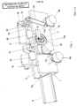
- the machine presents an elongated hollow base (1) in the sides of which are two longitudinal edges (2) which create a longitudinal passageway into which the postal payment slip slides perfectly, pulled by two pairs (3) of overlapping friction rollers.
- Each pair (3) of rollers is realized by two parallel overlapping shafts (4a and 4b), which cross the above longitudinal passageway transversally, under and above the forward feed track (5), covered by a counter-track (5a) respectively; the pulling action is operated by a pair of friction rollers which operate in conjunction with counter rollers positioned along the shafts (4a and 4b).
- the sliding track will have passing slots at the same level as the pairs of pulling rollers, so that the rollers of each pair rotate in contact with each other.
- a support guide (7) supporting the transversal blade (8) for cutting the slip can slide vertically between the longitudinal edges (2) in the center, run by two end blocks sliding within the two runners on the internal face of the longitudinal edges (2); this guide hangs on two end brackets (9) at the top of which there are two slots (9a) into which two circular cams (10) fit perfectly.
- the two cams are mounted eccentrically on a transversal shaft (11) which crosses and rests on the above edges (2).
- This shaft (11) are driven by the step motor (12) by means of a drive system with reduction gears consisting of a geared belt (13a) and a geared pulley (13) splined to the end of this shaft (11).
- the ink tape (16) is driven by means of a shaft (19), which is passed through a hole on the cartridge (17) pulled by a belt (20) which is driven by one of the two step motors (6b); a free wheel drives the shaft (19) only when the motor (6b) rotates in the direction for pulling the payment slip from the entrance towards the exit, in order to prevent the ink tape (16) from rewinding in the cartridge (17) should the motor (6b) rotate in the direction for pushing the uncut and unstamped payment slip towards the exit.
- Number (21) indicates the electronic reading head positioned on one of the longitudinal edges (2) close to the entrance for the slip. This is read through a small window on the counter-track (5a) which naturally must also have slots at the same level as the writing heads, the blade and the friction rollers.
- the stop and start of the step motors (6a and 6b) are controlled by an optic switch (22) whose luminuous band is interrupted as the slip passes through a small slot on the track (5) and on the counter-track (5a).
- the machine is switched on either by the cashier who presses a pushbutton or when the "Client Payment" pushbutton is pressed on the 'Bancomat' counter.
- the insertion of the slip between the track (5) and counter-track (5a) is immediately detected by two optic switches(22) which operate the step motors (6a and 6b) so that these rotate in the same direction ; the pulling movement occurs for as long as the optic switch (22) detects the passage of the edge of the slip, since it is preset so that the slip stops at the broken cutting line exactly under the blade (8).
- the electronic reading head (21) reads all the data on the slip and transmits these to the data processing center.
- the electronic control unit rotates the motors (6a and 6b) contrary to the previous direction in order to eject the slip.
- the electronic control unit operates the motor (12) which lowers the guides (7) to which the slip cut corresponds; step motors (6a and 6b) start rotating in opposite directions intermittently while the two halves of the slip are being printed by the writing heads and then continuously to eject the two halves in opposite directions, after printing has been completed.
- the receipt will be returned, duly stamped to the user, while the other half of the slip will be stored.
Abstract
Description
- This patent application relates to an automatic machine for reading, stamping cutting postal current account payment slips.
- Currently, prepared postal current account payment slips, complete with the amount due, the code of the consumer and the postal current account number to be credited are sent to the consumer for the payment of various services, such as electricity, gas or telephone.
- These slips consist of three parts, one of these, the receipt, is returned to the consumer once payment has been made, with the payment stamp, date on which payment is made and the name of the receiving office.
- These payments are usually made either at a post office, with payment of the amount due to the post office employee by presentation of the payment slip, or at bank counters. In this case, the amount to be paid is debited to the consumer's postal current account with the bank.
- To date, only automatic machines capable of stamping and cutting the payment slip are available. This is done after receipt of the cash payment by the office employee or after the office employee has controlled that the current account holder has sufficient funds to cover the amount to be debited to the current account.
- The aim of this invention is to further simplify postal current account payments with an automatic machine designed not only to stamp and cut these payment slips but also to read all the data and to transfer them to a data processing center which compares the data with those already available and to activate one or other of the functions it can perform, according to the result of the comparison which has been carried out.
- Obviously a machine capable of performing these operations should be connected to an electronic control unit, which determines its correct function, and supported by a data processing center capable of providing all the information it requires as well as adequately sorting the information it receives regarding the payment operations carried out.
- From the above it is easy to understand that the best, though not the only use of the machine in question, is the automatic debiting of the amounts to be paid, with prior verification of the availability of funds by the data processing center. The cashier would therefore only need to indicate the current account number of the consumer, thereby saving him the need to personally check the availability of funds and the accounting operations between the consumer and the supplying office.
- The advantages of the automatic machine in question increase if the possibility of combining it to a 'Bancomat' counter, is considered. This would provide clients with a bank service for payments of postal accounts even out of normal banking hours.
- In this case, the user would insert the magnetic 'Bancomat' card and the postal current account payment slip into the automatic machine together, according to the invention which is positioned next to the 'Bancomat'; by pressing a special pushbutton (Client Payments) on the 'Bancomat', the machine is enabled to read the data on the payment slip and to transmit these data to the 'Bancomat' which, firstly carries out all the necessary control procedures and then enables the machine to make the payment and return the receipt, duly stamped or alternatively, if no funds are available or if the client code has not been recognized, to return the payment slip complete.
- Initially, a first version of the machine was produced, for which Italian patent application No. 624 A/86 was filed.This first version includes a mechanism for gripping and drawing the postal payment slip over a guide on which the slip stops in the correct position, ready to be cut and stamped, after consent for the same has been given.
- These gripping and pulling mechanisms consist in fact of a pair of horizontal, parallel, overlapping friction rollers, one before and one after the cutting section with a guillotine blade operated by an eccentric wheel, cooperating with springs which return the blade to rest position.
- There are also two stamping sections before and after the cutting section; both of these are supported on opposite sides of the same blade support guide for cutting the payment slip transversally.
- The machine is also fitted with an electronic head for optic reading of all coded data written on the slip and their transmission to a data processing center.
- In the practical realization of this machine and its initial use, it was found that the stamping mechanism, mechanical in type, was not versatile enough, above all in terms of quality of the print on the payment slip and in up-dating of the device operated by an electric motor.
- In view of these problems, and while maintaining the structural and practical layout of the machine, as describes in the original Italian patent application, a second version of the machine in question was realized, for which Italian patent application No. 608 A/87 was filed. In the latter version, the mechanical stamping unit is replaced with a pin matrix printing system, like those used in type writers and calculators, which not only improves the quality of the print but also simplifies the date up-dating.
- The use of this pin matrix stamping system, has not only eliminated all the structural components connected to the previous mechanical stamping unit but has also involved various adaptations and modifications to the overall structure of the machine.
- The most important modification is the introduction of components for intermittent forward feed of the ink tape in synchronization with the ink tape of the payment slip, already cut and ready to be returned, so that writing pins can, with each stroke, print on the overlapped tape and paper which have been stopped momentarily.
- Clearly, as a consequence of this, the step motors which in the previous version only introduced the slip, and ejected it, after stamping and cutting, the two parts from the opposite sides, at a constant speed, currently are not only able to introduce the slip at a constant speed but also to pull the slip forward intermittently when the parts which have been cut are sorted for printing; for this purpose one of the two motors is used to drive the intermittent forward feed of the ink tape in synchronization with the intermittent lowering of the pins of the printing heads.
- For major clarity, the description of the invention continues with reference to the enclosed drawings which have only illustrative and certainly not limited value, in which:
- - fig. 1 is a schematic axonometric illustration of the machine with a front view of the invention;
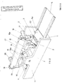
- - fig. 2 is a schematic axonometric illustration of the invention from the back;
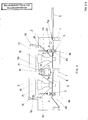
- - fig. 3 is a schematic orthonogal view of the machine accord- to the invention, without the longitudinal edge.
- The cover has been removed in all the figures for better illustration of the machine components.
- With reference to the above figures the machine presents an elongated hollow base (1) in the sides of which are two longitudinal edges (2) which create a longitudinal passageway into which the postal payment slip slides perfectly, pulled by two pairs (3) of overlapping friction rollers.
- Each pair (3) of rollers is realized by two parallel overlapping shafts (4a and 4b), which cross the above longitudinal passageway transversally, under and above the forward feed track (5), covered by a counter-track (5a) respectively; the pulling action is operated by a pair of friction rollers which operate in conjunction with counter rollers positioned along the shafts (4a and 4b).
- It is obvious that the sliding track will have passing slots at the same level as the pairs of pulling rollers, so that the rollers of each pair rotate in contact with each other.
- The shafts (4a) supporting each lower set of the pairs of friction rollers (3), are pulled by the respective step motors (6a and 6b) while the shafts above (4b) are moved by friction of the rollers (3).
- A support guide (7) supporting the transversal blade (8) for cutting the slip can slide vertically between the longitudinal edges (2) in the center, run by two end blocks sliding within the two runners on the internal face of the longitudinal edges (2); this guide hangs on two end brackets (9) at the top of which there are two slots (9a) into which two circular cams (10) fit perfectly. The two cams are mounted eccentrically on a transversal shaft (11) which crosses and rests on the above edges (2).
- The rotations of this shaft (11) are driven by the step motor (12) by means of a drive system with reduction gears consisting of a geared belt (13a) and a geared pulley (13) splined to the end of this shaft (11).
- There is a circular collar (13b) outside this pulley (13) which rotates between the two elments of a detector (14), which, each time the pulley (13) turns, identifies the passage of the only hole on this collar (13b) in order to stop the pulley (13) automatically after a complete turn of the pulley itself.
- Thanks therefore to the eccentric cam (10), the guide (7) support brackets (9) are pushed down and then lifted again to the top dead point, for each turn of the geared pulley (13).
- Before and after the above cutting unit, there are two identical pin matrix printing heads (15) supported by means of two shelves (15a) screwed to the internal side of the front longitudinal edge (2). These two heads are crossed by the same ink tape (16) which winds in its cartridge (17) which is supported, longitudinally and symmetrically to the machine and above the printing heads (15), by two end shelves (18) fixed to the top edge of the front longitudinal edge (2).
- The ink tape (16) is driven by means of a shaft (19), which is passed through a hole on the cartridge (17) pulled by a belt (20) which is driven by one of the two step motors (6b); a free wheel drives the shaft (19) only when the motor (6b) rotates in the direction for pulling the payment slip from the entrance towards the exit, in order to prevent the ink tape (16) from rewinding in the cartridge (17) should the motor (6b) rotate in the direction for pushing the uncut and unstamped payment slip towards the exit.
- It is evident that the counter-track (5a) must be provided with slots at the same level as the writing heads (15) in order to allow the pins to print on the slip below, in conjunction with the ink tape (16) between them.
- Number (21) indicates the electronic reading head positioned on one of the longitudinal edges (2) close to the entrance for the slip. This is read through a small window on the counter-track (5a) which naturally must also have slots at the same level as the writing heads, the blade and the friction rollers.
- The stop and start of the step motors (6a and 6b) are controlled by an optic switch (22) whose luminuous band is interrupted as the slip passes through a small slot on the track (5) and on the counter-track (5a).
- This description will make the operation of the automatic machine according to the invention, more easy to understand.
- The machine is switched on either by the cashier who presses a pushbutton or when the "Client Payment" pushbutton is pressed on the 'Bancomat' counter. The insertion of the slip between the track (5) and counter-track (5a) is immediately detected by two optic switches(22) which operate the step motors (6a and 6b) so that these rotate in the same direction ; the pulling movement occurs for as long as the optic switch (22) detects the passage of the edge of the slip, since it is preset so that the slip stops at the broken cutting line exactly under the blade (8).
- While the slip moves forward, the electronic reading head (21) reads all the data on the slip and transmits these to the data processing center.
- If the code of the current account holder is not identified or if there are not sufficient funds for the payment, the electronic control unit rotates the motors (6a and 6b) contrary to the previous direction in order to eject the slip.
- If the data processing center identifies the client code and there are sufficient funds available, the electronic control unit operates the motor (12) which lowers the guides (7) to which the slip cut corresponds; step motors (6a and 6b) start rotating in opposite directions intermittently while the two halves of the slip are being printed by the writing heads and then continuously to eject the two halves in opposite directions, after printing has been completed.
- Once this operation has been completed, the receipt will be returned, duly stamped to the user, while the other half of the slip will be stored.
Claims (2)
- a sliding track (5) in conjunction with the counter-track (5a) above the same, both being positioned over a hollow base (1) to the sides of which are fixed two longitudinal side walls (2) between which there is a distance exactly equal to the width of the slip; the slip is pulled into the track (5) and counter-track (5a) by means of two pairs of friction rollers (3) splined to shafts (4a and 4b) placed under and above the sliding surface of the slip respectively; the shafts (4a) are enclosed by their own step motors (6a and 6b) for the pair of rollers (3) placed before and after the cutting section (3) respectively;
- a central cutting station consisting of a guide(7) which supports a transversal blade (8) and which can slide vertically between the longitudinal edges (2) guided by two end blocks which slide within two guides on the internal face of these longitudinal edges (2); this guide (7) hangs on two end brackets (9) at the top of which are two slots (19a) in which two circular cams (19) fit perfectly. These cams are mounted eccentrically on a transversal shaft (11) which crosses and rests on the above edges (2); the shaft (11) whose rotations are operated by the step motor (2) by means of a drive system with reduction gears, consisting of a geared belt (13a) and a driven pulley (13) splined to the end of this shaft (11); thanks to the above eccentric cams (10), the brackets (9) supporting the slide (7) are pushed down and lifted again to the top dead point, for each turn of the geared pulley (13);
- two identical printing sections, symmetrically positioned before and after the above cutting unit, consisting of two pin matrix writing heads (15) supported by two support shelves (15a), which are screwed to the internal face of the front longitudinal edge (2) and both of which are crossed by the same ink tape (16) which winds within its respective cartridge (17) supported, longitudinally and symmetrically to the machine and above the printing heads (15) by means of two end shelves (18) fixed to the top edge of the front longitudinal edge (2); the ink tape (16) is pulled by a belt (19) passed through a hole on the cartridge (17) which is pulled by a belt (20) moved by one of the two step motors (6b). This belt has a free wheel which enables it to be moved only when the motor (6b) rotates in the direction for pulling the slip in the direction of the exit in order to prevent the ink tape from being rewound into the cartridge (17) should the motor (6b) rotate in the direction for pushing uncut and unprinted slips towards the exit; the above counter-track (5a) has slots at the same level as the printing heads (15) in order to allow the writing pins to print on the slip below in conjunction with the ink tape (16) placed between them;
- an electronic head (21) for reading the data contained on the slip, placed on one of the longitudinal edges (2) close to the slip entrance; which is read through a small window designed for this purpose on the counter - track (5a);
- an optic switch (22) which controls the stop and start of the step motors (6a and 6b), when the luminous band is interrupted by the passage of the front edge and the back edge of the slip respectively; this optic switch (22) is placed on the longitudinal side (2) so that the standard size slip, stops at its broken cutting line, exactly under the blade (8);
- if the client code is identified and if there are sufficient funds for the payment available, an electronic control unit operates the motor (12) which through the eccentric wheel splined (19) to the shaft (11), lowers the guide (7) to which the slip cut corresponds. This subsequently activates the two motors (6a) and (6b). If the account holder code is not identified or there are not sufficient funds, the electronic control unit activates both the step motors (6a and 6b), so that these rotate simultaneously and equiversa, thereby ejecting the slip.
Priority Applications (1)
| Application Number | Priority Date | Filing Date | Title |
|---|---|---|---|
| AT87830427T ATE75553T1 (en) | 1987-02-19 | 1987-12-02 | AUTOMATIC MACHINE FOR READING, PRINTING AND DETACHING POSTAL ACCOUNT CERTIFICATES|RECEIPT. |
Applications Claiming Priority (2)
| Application Number | Priority Date | Filing Date | Title |
|---|---|---|---|
| IT8700608A IT1216941B (en) | 1987-02-19 | 1987-02-19 | IMPROVEMENT OF AN AUTOMATIC MACHINE FOR READING, STAMPING AND CUTTING OF POSTAL ACCOUNT BULLETINS |
| IT60887 | 1987-02-19 |
Publications (3)
| Publication Number | Publication Date |
|---|---|
| EP0286768A2 true EP0286768A2 (en) | 1988-10-19 |
| EP0286768A3 EP0286768A3 (en) | 1989-08-16 |
| EP0286768B1 EP0286768B1 (en) | 1992-04-29 |
Family
ID=11291621
Family Applications (1)
| Application Number | Title | Priority Date | Filing Date |
|---|---|---|---|
| EP87830427A Expired - Lifetime EP0286768B1 (en) | 1987-02-19 | 1987-12-02 | Automatic machine for the reading stamping, and tearing of postal current account receipts |
Country Status (6)
| Country | Link |
|---|---|
| EP (1) | EP0286768B1 (en) |
| AT (1) | ATE75553T1 (en) |
| DE (1) | DE3778693D1 (en) |
| ES (1) | ES2032864T3 (en) |
| GR (1) | GR3005309T3 (en) |
| IT (1) | IT1216941B (en) |
Cited By (2)
| Publication number | Priority date | Publication date | Assignee | Title |
|---|---|---|---|---|
| EP0644055A2 (en) * | 1993-09-22 | 1995-03-22 | Brother Kogyo Kabushiki Kaisha | Print tape forming apparatus having tape cutting mechanism |
| US7226494B1 (en) * | 1997-04-23 | 2007-06-05 | Neopost Technologies | Secure postage payment system and method |
Citations (3)
| Publication number | Priority date | Publication date | Assignee | Title |
|---|---|---|---|---|
| US4048891A (en) * | 1976-10-26 | 1977-09-20 | Gerber Garment Technology, Inc. | Cutter mechanism for cutting sheet material |
| GB2131353A (en) * | 1982-12-13 | 1984-06-20 | Byteissue Limited | Cheque printing apparatus |
| US4472626A (en) * | 1981-01-16 | 1984-09-18 | Frid Salomon R | Information and protection system for checks and credit cards |
-
1987
- 1987-02-19 IT IT8700608A patent/IT1216941B/en active
- 1987-12-02 ES ES198787830427T patent/ES2032864T3/en not_active Expired - Lifetime
- 1987-12-02 EP EP87830427A patent/EP0286768B1/en not_active Expired - Lifetime
- 1987-12-02 AT AT87830427T patent/ATE75553T1/en not_active IP Right Cessation
- 1987-12-02 DE DE8787830427T patent/DE3778693D1/en not_active Expired - Fee Related
-
1992
- 1992-07-29 GR GR920401642T patent/GR3005309T3/el unknown
Patent Citations (3)
| Publication number | Priority date | Publication date | Assignee | Title |
|---|---|---|---|---|
| US4048891A (en) * | 1976-10-26 | 1977-09-20 | Gerber Garment Technology, Inc. | Cutter mechanism for cutting sheet material |
| US4472626A (en) * | 1981-01-16 | 1984-09-18 | Frid Salomon R | Information and protection system for checks and credit cards |
| GB2131353A (en) * | 1982-12-13 | 1984-06-20 | Byteissue Limited | Cheque printing apparatus |
Cited By (5)
| Publication number | Priority date | Publication date | Assignee | Title |
|---|---|---|---|---|
| EP0644055A2 (en) * | 1993-09-22 | 1995-03-22 | Brother Kogyo Kabushiki Kaisha | Print tape forming apparatus having tape cutting mechanism |
| EP0644055A3 (en) * | 1993-09-22 | 1996-02-07 | Brother Ind Ltd | Print tape forming apparatus having tape cutting mechanism. |
| US7257558B2 (en) * | 1996-04-23 | 2007-08-14 | Neopost Technologies | System and method for conducting a financial transaction between a sender and recipient of a mail piece |
| US7769694B2 (en) | 1996-04-23 | 2010-08-03 | Neopost Technologies | Secure postage payment system and method |
| US7226494B1 (en) * | 1997-04-23 | 2007-06-05 | Neopost Technologies | Secure postage payment system and method |
Also Published As
| Publication number | Publication date |
|---|---|
| EP0286768B1 (en) | 1992-04-29 |
| ATE75553T1 (en) | 1992-05-15 |
| IT8700608A0 (en) | 1987-02-19 |
| GR3005309T3 (en) | 1993-05-24 |
| DE3778693D1 (en) | 1992-06-04 |
| IT1216941B (en) | 1990-03-14 |
| ES2032864T3 (en) | 1993-03-01 |
| EP0286768A3 (en) | 1989-08-16 |
Similar Documents
| Publication | Publication Date | Title |
|---|---|---|
| US5433364A (en) | Card package production system with burster and carrier verification apparatus | |
| US5388815A (en) | Embossed card package production system with modular inserters for multiple forms | |
| US4266121A (en) | Receipt slip issuing apparatus | |
| US4280036A (en) | Banking apparatus using passbooks | |
| US3850299A (en) | Card transport and capture mechanism | |
| US4361086A (en) | Serial printer for objects movable in a predetermined direction | |
| US4623081A (en) | Burster apparatus for continuous forms | |
| GB2344918A (en) | System for the sale of printed information from an automatic vending machine | |
| EP0036266B1 (en) | Banknote dispensing machine with delivery device for the receipt for the banknotes dispensed | |
| US6386445B2 (en) | Medium issuing apparatus using paper roll medium and automatic teller machine using the apparatus | |
| GB2026392A (en) | Printer | |
| EP0286768A2 (en) | Automatic machine for the reading stamping, and tearing of postal current account receipts | |
| JPS5839353B2 (en) | Passbook handling device | |
| US4337890A (en) | Method of preparing and processing receipts for customers of parking lots or the like | |
| US5163671A (en) | Automated single roller ticket processor with passive ticket reversal | |
| GB2143356A (en) | Systems for the issue of tickets | |
| US4961657A (en) | Record media drive mechanism for dot matrix printer | |
| JP3235363B2 (en) | Magnetic recording device and ticket issuing machine using the same | |
| JPS6017145B2 (en) | Passbook handling device | |
| JPS59229373A (en) | Bankbook handling apparatus | |
| FR2468166A1 (en) | MACHINE FOR PRINTING, ISSUING AND ACCOUNTING FOR TICKETS AND VALUES | |
| EP0145476A2 (en) | Ticket handling apparatus | |
| JP2809352B2 (en) | Card processing equipment | |
| JPS597095Y2 (en) | Slip issuing device | |
| JPH0257787B2 (en) |
Legal Events
| Date | Code | Title | Description |
|---|---|---|---|
| PUAI | Public reference made under article 153(3) epc to a published international application that has entered the european phase |
Free format text: ORIGINAL CODE: 0009012 |
|
| AK | Designated contracting states |
Kind code of ref document: A2 Designated state(s): AT BE CH DE ES FR GB GR LI LU NL SE |
|
| PUAL | Search report despatched |
Free format text: ORIGINAL CODE: 0009013 |
|
| AK | Designated contracting states |
Kind code of ref document: A3 Designated state(s): AT BE CH DE ES FR GB GR LI LU NL SE |
|
| 17P | Request for examination filed |
Effective date: 19900206 |
|
| 17Q | First examination report despatched |
Effective date: 19910412 |
|
| GRAA | (expected) grant |
Free format text: ORIGINAL CODE: 0009210 |
|
| AK | Designated contracting states |
Kind code of ref document: B1 Designated state(s): AT BE CH DE ES FR GB GR LI LU NL SE |
|
| REF | Corresponds to: |
Ref document number: 75553 Country of ref document: AT Date of ref document: 19920515 Kind code of ref document: T |
|
| REF | Corresponds to: |
Ref document number: 3778693 Country of ref document: DE Date of ref document: 19920604 |
|
| ET | Fr: translation filed | ||
| PGFP | Annual fee paid to national office [announced via postgrant information from national office to epo] |
Ref country code: SE Payment date: 19921202 Year of fee payment: 6 Ref country code: GB Payment date: 19921202 Year of fee payment: 6 |
|
| PGFP | Annual fee paid to national office [announced via postgrant information from national office to epo] |
Ref country code: ES Payment date: 19921204 Year of fee payment: 6 Ref country code: CH Payment date: 19921204 Year of fee payment: 6 |
|
| PGFP | Annual fee paid to national office [announced via postgrant information from national office to epo] |
Ref country code: FR Payment date: 19921211 Year of fee payment: 6 Ref country code: BE Payment date: 19921211 Year of fee payment: 6 |
|
| PGFP | Annual fee paid to national office [announced via postgrant information from national office to epo] |
Ref country code: LU Payment date: 19921214 Year of fee payment: 6 |
|
| PGFP | Annual fee paid to national office [announced via postgrant information from national office to epo] |
Ref country code: GR Payment date: 19921215 Year of fee payment: 6 |
|
| PGFP | Annual fee paid to national office [announced via postgrant information from national office to epo] |
Ref country code: NL Payment date: 19921231 Year of fee payment: 6 Ref country code: AT Payment date: 19921231 Year of fee payment: 6 |
|
| PGFP | Annual fee paid to national office [announced via postgrant information from national office to epo] |
Ref country code: DE Payment date: 19930224 Year of fee payment: 6 |
|
| REG | Reference to a national code |
Ref country code: GR Ref legal event code: FG4A Free format text: 3005309 |
|
| REG | Reference to a national code |
Ref country code: ES Ref legal event code: FG2A Ref document number: 2032864 Country of ref document: ES Kind code of ref document: T3 |
|
| PLBE | No opposition filed within time limit |
Free format text: ORIGINAL CODE: 0009261 |
|
| STAA | Information on the status of an ep patent application or granted ep patent |
Free format text: STATUS: NO OPPOSITION FILED WITHIN TIME LIMIT |
|
| EPTA | Lu: last paid annual fee | ||
| 26N | No opposition filed | ||
| PG25 | Lapsed in a contracting state [announced via postgrant information from national office to epo] |
Ref country code: LU Free format text: LAPSE BECAUSE OF NON-PAYMENT OF DUE FEES Effective date: 19931202 Ref country code: GB Effective date: 19931202 Ref country code: AT Effective date: 19931202 |
|
| PG25 | Lapsed in a contracting state [announced via postgrant information from national office to epo] |
Ref country code: SE Effective date: 19931203 |
|
| PG25 | Lapsed in a contracting state [announced via postgrant information from national office to epo] |
Ref country code: LI Effective date: 19931231 Ref country code: CH Effective date: 19931231 Ref country code: BE Effective date: 19931231 |
|
| BERE | Be: lapsed |
Owner name: AUTOMA DI SENSI GIAMPIERO & BIAGETTI PATRIZIA - Effective date: 19931231 |
|
| PG25 | Lapsed in a contracting state [announced via postgrant information from national office to epo] |
Ref country code: GR Free format text: THE PATENT HAS BEEN ANNULLED BY A DECISION OF A NATIONAL AUTHORITY Effective date: 19940630 |
|
| PG25 | Lapsed in a contracting state [announced via postgrant information from national office to epo] |
Ref country code: NL Effective date: 19940701 |
|
| GBPC | Gb: european patent ceased through non-payment of renewal fee |
Effective date: 19931202 |
|
| NLV4 | Nl: lapsed or anulled due to non-payment of the annual fee | ||
| PG25 | Lapsed in a contracting state [announced via postgrant information from national office to epo] |
Ref country code: FR Effective date: 19940831 |
|
| REG | Reference to a national code |
Ref country code: CH Ref legal event code: PL |
|
| PG25 | Lapsed in a contracting state [announced via postgrant information from national office to epo] |
Ref country code: DE Effective date: 19940901 |
|
| REG | Reference to a national code |
Ref country code: FR Ref legal event code: ST |
|
| PG25 | Lapsed in a contracting state [announced via postgrant information from national office to epo] |
Ref country code: ES Free format text: LAPSE BECAUSE OF NON-PAYMENT OF DUE FEES Effective date: 19941203 |
|
| REG | Reference to a national code |
Ref country code: GR Ref legal event code: MM2A Free format text: 3005309 |
|
| EUG | Se: european patent has lapsed |
Ref document number: 87830427.8 Effective date: 19940710 |
|
| REG | Reference to a national code |
Ref country code: ES Ref legal event code: FD2A Effective date: 19950112 |